切内里基线隧道——穿越瑞士阿尔卑斯山脉的平轨铁路线南段的施工经验
世界最长的隧道在哪个国家
世界最长的隧道在哪个国家世界最长的隧道在哪个国家我们都知道,世界上的隧道数不胜数,那你知道世界上最长的隧道在哪个国家吗?以下是店铺整理的世界最长的隧道在哪个国家,仅供参考,大家一起来看看吧。
人类的智慧,勒奇山隧道(Loetschberg tunnel)。
提起瑞士,人们总会第一时间联想到著名的瑞士手表。
不过现在,瑞士人还会对外来人说,令他们感到骄傲的还有另外一样东西——勒奇山隧道(Loetschberg tunnel)。
世界著名隧道之一。
在瑞士南部伯尔尼阿尔卑斯山,辛普朗隧道的西北。
海拔2,690米,长14公里,建于1907—1913年。
从坎德施泰格到戈彭施泰因,筑有铁路,通达伯尔尼和意大利的米兰。
穿越瑞士阿尔卑斯山脉的勒奇山隧道(Loetschberg tunnel)于当地时间15日隆重开通,成为全球最长的陆上隧道,并令欧洲中部穿越阿尔卑斯山的交通迈向新纪元。
首趟列车在位于北部城市弗鲁蒂根的隧道入口冲过了一幅书写“勒奇山──连接欧洲”的条幅(见图),现场有数千名官员和民众见证了这一历史性时刻。
有关当局当天还安排了铜管乐队和烟花助兴。
勒奇山隧道长达35公里,建筑工程历时8年,耗资43亿瑞士法郎(约270亿元人民币),它把德国和意大利之间的列车旅程由3.5小时缩减至2小时以下。
据悉,在今年12月隧道将实现设计最大通过能力,每天将有42趟客运列车和80趟货运列车通过隧道。
瑞士多山区,因此大多数陆路交通依靠建设隧道实现贯通。
瑞士还打算兴建长达60公里的铁路隧道,一旦建成,从苏黎世到米兰的旅程将缩减至2.5小时。
目前世界最长的隧道是海底隧道,但勒奇山隧道是全球最长的陆上隧道。
运行速度普通货物列车:100km/h特别货物列车:160km/h普通旅客列车:200km/h特快旅客列车:250km/h世界上最长的陆上隧道:勒奇山隧道提起瑞士,人们总会第一时间联想到著名的瑞士手表。
不过现在,瑞士人还会对外来人说,令他们感到骄傲的还有另外一样东西——勒奇山隧道。
世界上最长的穿山隧道

世界上最长的穿山隧道世界上最长的穿山隧道在哪个国家呢?长度是多长?下面由店铺告诉你~瑞士开通了世界最长铁路隧道—圣哥达基线隧道,全长57.1公里,超过日本靑函隧道。
世界最长铁路隧道—圣哥达基线隧道于1日在其南北两端入口处举行了开通仪式。
随后,列车分别从两端站台出发穿越隧道。
在首班列车上,乘坐着瑞士内阁成员和国会议员、德国默克尔、法国总统奥朗德、意大利伦齐等邻国元首和经抽签选中的幸运市民。
圣哥达基线隧道计划12月开始正式投入使用,在此之前将进行试运行,以确其保安全性。
此隧道从90年代开始施工,全工程造价122亿法郎约合人民币13650亿元。
全长57.1公里,超过日本靑函隧道(53.9公里),成为世界最长隧道。
圣哥达基线隧道-你不可不知的八件事1. 圣哥达是个神话作为1291年首批联邦州结盟之处,及对哈布斯堡王朝反抗的诞生地,圣哥达享有独特的光圈。
无论马特洪峰(Matterhorn)还是任何其他瑞士山峰,都没有这座山体所具有的象征意义:联邦的摇篮、阿尔卑斯山脉的中心、人员交通的枢纽、欧洲大河的源头、瑞士各文化的十字路口,以及祖国独立、凝聚力与认同感的象征。
用纳沙泰尔大学(l’Université de Neuchâtel)中世纪史教授让-丹尼尔·莫勒罗德(Jean-Daniel Morerod)的话说就是“大杂烩”,他在这篇文章(法)中将之解释为“13世纪圣哥达商业重要性与反抗哈布斯堡群体起义的巧合”。
对作家彼得·冯·马特(Peter von Matt)来说,圣哥达可以被看作是用于“瑞士自我荣耀”的“赫尔维蒂的西奈山”。
然而正如彼得·冯·马特在这个采访中谈到的,人们所述说关于圣哥达的一切并非都是真有其事。
历史学家拉尔夫·阿什万登(Ralph Aschwanden)回忆道,在很长的时间里,人们甚至以为圣哥达是阿尔卑斯山脉的最高峰,这种错误认识直到18世纪才得到纠正。
大断面隧道设计施工中的关键问题

2018/9/20
8
意大利从罗马到佛罗伦萨的线路,长度237km, 其中穿越阿尔卑斯山的线路实际长度只有 78.2km,而且隧道的总延长则达85km。其中, 主隧道长度为73km,辅助隧道长度达12km。
2018/9/20
9
台湾正在修建的台北到高雄的高速铁路全长 333km,共有总延长39km的50座隧道,最长 的隧道约 8.4km ,隧道比重为 11.7 %。其中 36 座隧道将采用掘进机法或钻爆法施工,其3 14 15 16 17 18 19 20
野三关隧道
北天山隧道 吕梁山隧道 大别山隧道 霞浦隧道 长梁山隧道 东秦岭隧道 堡镇隧道 南梁隧道 通海隧道 圆梁山隧道 金寨隧道 大巴山隧道 齐岳山隧道 大瑶山一号
13845
13573 13365 13251 13124 12782 12268 11588 11451 11115 11068 10682 10655 10469 10080
长度(km) 57.1 55.0 53.9 52.1 50.5 34.6 32.8 28.4 27.9 26.5 25.8 24.7 23.9 22.2 22.2 20.1 20.0 20.0 20.0 19.8 19.8 19.7 19.2 19.1 19.0 18.7 18.6 18.5 18.5 16.6 16.3 15.4 15.4
15.3 15.2 15.1 15.0 15.0 15.0 15.0 15.0 14.9 14.6 14.6 14.6 14.3 14.3 14.0 13.9 13.8 13.6 13.5 13.5 13.5 13.4 13.4 13.3 13.3 13.3 13.2 13.1 13.0 12.8 12.8 12.7 12.5 12.3 12.3
瑞士圣哥达深埋长隧洞工程的设计思路、地质条件与施工方法

维普资讯
设 计 与施工
水利 规划 与设 计
20 0 6年 第 5期
③ 赛 德 润 ( ern S du )标 段 ,长 6 8k . m,采 用 常 规 钻爆 法掘 进施 工 ,施 工 支 洞 为 水平 段 长 9 0 9 m、竖 井段 深 8 5m。④ 法 意 多 ( ad )标 段 ,长 1 . 3 F io 46
宏 伟 的地下 工程 ,并 到达 8 5 埋 深 的施 工 竖 井 3m
中参观 了掌 子面开 挖现 场 ,实地 了解 和体验 了该工 程 的设计 思 想 、地 质条 件 、施工 组织 、安 全管理 及 钻 爆法 施工 等情况 。
r ,最 小 的隧 道 截 面 积 为 4 r 。 以上 设 计 参 数 满 f l 1f l 足 了圣 哥 达高速 铁路 的基 本要 求 。 工程 分五个 施 工 标 段 ,根 据 不 同 的地 质 条 件 ,
最大 ( 深达 2 0 m) 的隧道 工程 一一圣 哥 达铁路 最 40 隧道 工程 就在瑞 士境 内。笔者 近期 赴瑞 士考察 了这
一
案 ,即建设 2条 平 行 的 隧 道 ,长 5 k 7 m,洞 径 9 m,
互 为紧急 备用 ,在 隧道 内建有 多功 能 中转站 。在 这 2 平行 的 隧道 中 ,每 3 5r 建 一 个 连接 支 洞 。隧 条 2 f l 道 的最大 坡度 小于 0 7 ,最 高 点 高程 位 于 隧道 中 . 间 ,为 5 0 r。在 平 面上 最 小 的 转 弯半 径 为 5 0 5 l f 00
润 ( er n 标 段 ,该 标 段 将 遇 到 地 质 条 件 较 差 的挤 压 性 岩 体 段 , 承包 商 利 用 8 5 深 的交 通 竖 井 , 在 其 底 部 双 S du ) 3m
全球最长的铁路隧道在瑞士开通,还有超现实开幕式

全球最长的铁路隧道在瑞士开通,还有超现实开幕式世界上最长、最深的火车隧道 6 月 1 号在瑞士正式开通。
今年 12 月隧道全线开通后,乘客从瑞士苏黎世到意大利米兰,将节省一个小时的旅程。
这条隧道名为“圣哥达基线隧道”(Gotthard base tunnel),位于瑞士东南部,南起小镇Bodio,北至 Erstfeld,长达 57.5 公里,取代了日本于 1988 年落成的 Seikan 隧道(53.9公里),成为世界之最。
为庆祝这条造价 120 亿美元、耗时 17 年建成的浩大工程,一场不走寻常路、超现实风格的开幕式在隧道北端的 Erstfeld 上演。
毛色各异的野山羊、插着翅膀的大头天使、穿橙黄色制服的建筑工人……600 个舞蹈演员、杂技演员、歌手等装扮成不同角色,由德国戏剧导演 Volker Hesse 带领。
根据隧道官网介绍,这个“和项目分量相对应的开幕式”,其目标是“展示瑞士价值,诸如创新、精确、可靠”。
一个半裸演员装扮成带有翅膀、有巨型头部婴儿,在建筑工人头上盘旋徘徊,代表着在隧道修建过程中死亡的八个工人。
半裸的演员。
在表演中,一个男演员坐下来吃午饭。
表情不丰富的半裸演员。
有观众在推特上问,“为什么会有一只死羊羔?”被称为“瑞士世纪工程”的圣哥达基线隧道,选择了更小众前卫的开幕方式,而非正襟危坐。
但开幕式上这些欧洲政要可能会提醒人们隧道的外交和经济地位:瑞士联邦总统施奈德-阿曼、德国总理默克尔、法国总统奥朗德、意大利总理伦齐都参加了第一天的开幕活动。
野生山羊作为阿尔卑斯山脉地区的本地动物,在开幕式中占据重要地位。
根据 BBC 报道,这条埋在阿尔卑斯山脉下的捷径,将给欧洲货运带来显著便利。
每年大约 100 万卡车的货物将改由火车经此运输,每天 260 辆货运火车和 65 辆客运火车穿行全程,仅需 17 分钟。
意大利的红酒送到荷兰,德国汽车运往希腊,阿尔卑斯山脉是必经之路,现在能够以更快、更安全、更便宜的方式实现。
欧洲长而深的基线隧道

欧洲长而深的基线隧道佚名【期刊名称】《现代城市轨道交通》【年(卷),期】2016(000)005【总页数】4页(P94-97)【正文语种】中文在欧洲,21 世纪已成为基线隧道的世纪。
以前所未有的深度开挖穿过高大山区的7座长而深的隧道,经受着多方面的特殊挑战。
首先要尽可能查明隧道穿越地层的地质、水文地质和土工特性。
隧道在特大的埋深下,通常会遇到非常高的岩石应力、岩石的塑性或挤压、岩爆、断层和剪切、极大的水压力,以及岩石的高温度。
这些问题影响到隧道的施工和日后的运营,必须研究解决这些复杂问题的方法和措施。
其次要对工程进行风险评估和风险控制。
隧道工程长达数十公里,施工条件极为复杂,潜在风险频仍,工期大都超过 10 年以上,对主体工程的风险必须重在预防,严加控制。
此外,对社会、对周围环境的影响应该密切注意,如何采取相应措施减小对周围环境的影响,如何与当地居民进行信息沟通,以减小对工程开展的阻力,应该加以重视并纳入议事日程。
再者是施工方面。
包括修建非常长的多用途的(勘查、服务、施工出入口)隧道,开挖拼装(拆卸)掘进机的大型地下洞室,置备施工机械设备,完善施工通风系统,安全运送大型物件;优选开挖主隧道和横通道的方法,控制开挖速度和选择相应的支护衬砌系统。
在高大山区选择施工出入口特别困难,往往需要建造深达数百米的竖井或具有陡峭坡度的长大的施工出入口。
主隧道的规划设计必须把保证列车运行安全与特殊情况下的应急处置作为首要目标。
施工中必须重视工人的人身安全、施工安全和周围环境安全。
欧洲 7 座基线隧道的位置示意图见图 1。
2.1 勒奇山隧道(Lotschberg Base Tunnel)这是欧洲第1座穿越阿尔卑斯山的基线隧道,全长 34.6 km,埋深 2 000 m。
主隧道是 2 座平行的单线隧道,间距 40~60 m。
两主隧道之间用横通道连接,其间距为 330 m。
在隧道施工中,主隧道 2 0% 的长度采用直径 9.43 m 的掘进机开挖,80% 采用钻爆法施工。
罗信隧道讲座材料

新奥法是应用岩体力学理论,以维护和利用围岩的自稳能力为基本出
发点,采用锚杆和喷射混凝土为主要支护手段,及时地对围岩进行支 护,控制围岩的变形和松弛,使围岩成为支护体系的组成部分,并通过 对围岩和支护的量测、监控来指导隧道施工的方法。
3工法介绍
3.6新奥法的力学特征
圆形洞室计算简图
3工法介绍
次衬砌) 喷射混凝土特点:
a) 喷射混凝土支护、施作速度快、早期强度高、密实度好、与隧道围
岩紧密粘结;
b) 隧道开挖后,及时施作喷射混凝土支护,可以起到封闭岩面、填充
坑凹及缝隙、防止围岩风化松动、维护和提高围岩的整体性、帮助 围岩发挥自身的结构作用、调整围岩应力分布,防止应力集中,控 制围岩变形,防止掉块、坍塌作用。
/1528.51万米。其中特长隧道902处/401.32万米,长隧道3841处/659.93 万米。
截至目前,全国已运营的10km以上(包括10km)的公路山岭隧道有8座
(见下表)。
1概 述
公路隧道一般可分为三类
1、山岭公路隧道
以钻爆法、明挖法施工 为主
2、城市公路隧道
以钻爆法、明挖法、盾 构法施工为主
小结:隐蔽工程,风险大,施工质量管控难度大,地质起决定性作用。
3工法介绍
3.1目前主要的工法
新意法(岩土控制变形分析法):适用于软弱围岩,广泛应用
于意大利的公路和铁路隧道,在我国尚未得到真正应用;
挪威法:适用于较好围岩,最大特点是以一次支护作为永久衬
砌(通常一次衬砌采用高质量的湿喷钢纤维混凝土);
新奥法:当前国内山岭公路隧道设计施工采用的主流方法(后
文予以详细介绍)。
3工法介绍
3.2新意法 (ADECO-RS)
全球最长的隧道在哪里
全球最长的隧道在哪里你知道全球最长的隧道是在哪里吗?下面就让小编告诉你吧。
1.隧道的简介隧道是指在既有的建筑或土石结构中挖出来的通道,是埋置于地层内的工程建筑物,是人类利用地下空间的一种形式。
隧道可分为交通隧道,水工隧道,市政隧道,矿山隧道。
1970年国际经济合作与发展组织召开的隧道会议综合了各种因素,对隧道所下的定义为:“以某种用途、在地面下作用任何方法规定形状和尺寸修筑的断面积大于2㎡的洞室。
”2.组成西安至南京铁路东秦岭隧道隧道的结构包括主体建筑物和附属设备两部分。
主体建筑物由洞身和洞门组成,附属设备包括避车洞、消防设施、应急通讯和防排水设施,长大隧道还有专门的通风和照明设备。
高速铁路隧道内不设置供养护维修人员待避的洞室,但应考虑设置存放维修工具和其他业务部门需要的专用洞室。
高速铁路隧道内应设置安全空间和贯通的救援通道。
安全空间应设置在距线路中心处3.0m以外,单线隧道在救援通道一侧设置,多线隧道在双侧设置。
安全空间的高度不应小于2.2m,宽度不应小于0.8m。
救援通道设置在安全空间一侧,距线路中心不应小于2.3m。
救援通道的宽度不宜小于1.5m,高度不应小于2.2m。
高速铁路长度大于50m的隧道,应在洞内设置余长电缆腔,并应与专用洞室结合设置。
余长电缆腔沿隧道两侧交错布置,每侧间距宜为500m。
长度500-1000m的隧道,可只在其中部设置一处。
长度500m以上的隧道应设置作业照明设置,长度5km及以上的隧道还应设置应急照明。
高速铁路长隧道及特长隧道应结合辅助坑道情况设置紧急出口,紧急出口上方应设标示牌和紧急照明设施。
紧急出口通道的设置应符合相关规定。
3.分类铁路隧道分类:(1)特长隧道:全长10000m以上;铁路隧道分类:(2)长隧道:全长3000m以上至10000m,含10000m;铁路隧道分类:(3)中隧道:全长500m以上至3000m,含3000m;铁路隧道分类:(4)短隧道:全长500m及以下。
世界各国海底隧道盘点滔滔沧海变通途

52 交通建设与管理EXCLUSIVE专题策划世界各国海底隧道盘点滔滔沧海变通途文 / 本刊记者 王楠楠海峡像一道天堑将大陆与大陆,大陆与海岛,海岛与海岛之间隔开,这给人们的生活、旅行带来许多不便。
于是,人们设计建造接通海峡两岸的海底隧道。
海底隧道不占地,不妨碍航行,不影响生态环境,是一种非常安全的全天候的海峡通道。
事实上,人类建海底隧道的梦想和尝试早在19世纪的拿破仑时代已经萌芽,当时的法国人就设想着在英法海峡之间修建一条隧道,并进行了两次开挖,但最后都因技术和战争的原因而搁浅下来。
两个多世纪以后,直到1993年,这条隧道才完全贯通并投入运营。
确切而言,世界范围内海底隧道的建设始于上世纪的40年代。
1942年,日本在关门海峡修建了第一条海底隧道。
目前,全世界范围内已建成和计划建设的海底隧道有20多条,主要分布在日本、美国、西欧、中国的香港九龙等地区。
作为一种不占地、不妨碍航行、不影响生态环境的非常安全的全天候的海峡通道,海底隧道在世界各国经济、生活联系日益加深的今天,这种实现各大陆陆路相通的连接方式,越来越受到瞩目。
【世界第一长】圣哥达基线隧道圣哥达基线隧道是穿越圣哥达山口的线路(隧道),是欧洲南北轴线上穿越阿尔卑斯山最重要的通道之一。
建设用时17年,共耗资120亿瑞士法郎(约合110亿欧元)。
长约57公里,穿越瑞士阿尔卑斯山脉底部,距地面约2438.4米,超过日本的青函隧道,成为目前世界上最长与最深的隧道(含铁路隧道和公路隧道)。
其实早在1947年,瑞士工程师格鲁纳就绘出了圣哥达基线隧道的设计草图,但受工程审批的繁文缛节、成本高昂等因素影响,隧道建设直至1999年才开始,由瑞士联邦铁路的全资子公司——阿尔卑斯枢纽计划圣哥达股份公司承担圣哥达山底隧道工程的建造。
该隧道开工后,分别从南北两端同时开始工作,2000多名工人开始参与到隧道的挖掘工作中,夜以继日地将3100万吨山石挖出,这些石头超过了200万辆卡车的装载量,其中还有8名工人不幸遇难。
长隧道工程TBM施工风险分析及对策

长隧道工程T B M施工潜在风险分析及对策辽宁省水利水电工程局TBM公司邮编113214 候秉钧喻正信摘要:本文从TBM施工安全角度,针对锦萍东引一号隧道施工中可能存在的潜在风险进行了分析和预测,并据此从施工作业各层面提出相应对策。
关键词:TBM、潜在风险、对策Countermeasures for the latent risks in constructing long tunnel withTBMAbstract: This article takes the view of construciton safety with TBM, makes analysis and forecast on the possible latent risks in Jingping East Water-introducing No.1 Tunnel construction, and presents the relevant countermeasuresKEY WORD:TBM latency Hazard countermeasure一、地质风险掘进机施工的核心优点速度快,开挖速度一般是钻爆法的3-5倍,掘进机设计一旦确定,掘进速度则取决于反应管理水平的TBM利用率和岩石破碎的难易程度即岩性。
掘进机性能的发挥很大程度上依赖工程地质条件和水文地质条件,岩石的单轴抗压强度和硬度将决定掘进机掘进效率和工程成本。
瑞士费尔艾那隧道施工表明【1】,石英含量在25%以下时掘进困难不大,岩石节理太密容易坍塌,而十分完整则会影响掘进速度,秦岭隧道片麻岩段掘进曾花费5小时才掘进一个循环,秦岭I线隧道混合花岗岩实际平均钻掘速度P=1.33m/h,混合片麻岩实际平均钻掘速度P=1.08m/h,大伙房TBM3岩石相对完整地段的缓慢掘进(三小时一循环)也说明了此点。
根据地质调查,C4标地段的岩石种类大多为大理岩,但有局部1000m中厚层中细粒砂岩(T3)和互层状砂岩、板岩(T3),岩石抗压强度104~152 MPa,尤其石英含量85%,不仅会加剧刀具的磨损,频繁的换刀也会严重制约掘进速度。
瑞士公路交通建设简介
瑞士公路交通建设简介我国目前正处于交通运输基础设施大建设大发展的高峰时段,山区公路和桥隧比例明显增多,施工难度明显加大,安全风险增加,为了学习借鉴国外山区公路及长大隧道工程建设安全管理经验,提高我国交通基础设施建设安全管理水平,拓宽我国交通建设工程安全管理工作思路,交通运输部于2010年1月21日至2月8日,山区公路和长大隧道安全管理培训团一行11人(考察团名单附后),在交通运输部质监总站李彦武站长带领下,赴瑞士进行了为期21天的培训考察。
培训行程包括走访瑞士工程安全监督机构、技术咨询公司、地下试验场以及桥梁、隧道等四个在建工程项目部,并参观了施工现场,对瑞士工程建设安全管理理念有了更深刻的认识,达到了预期目的。
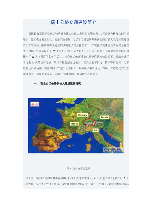
具体情况汇报如下:一、瑞士山区公路和长大隧道建设情况图1 瑞士地理位置图瑞士位于欧洲中南部的多山内陆国,但瑞士交通非常便利,6 万公里公路(见图2)、5 千公里铁路(见图3)交错于全国。
这些稠密的道路网,有七分之一在地下,隧道比例非常高。
图2 瑞士铁路网图3 瑞士公路网瑞士是有名的隧道之国,仅圣哥达阿尔卑斯山口,57公里的铁路线就有72个隧道。
著名的隧道有从最初的穿越阿尔卑斯山的原始小道到今天供机动车辆高等级公路和高速铁路,瑞士经历了漫长的过程。
阿尔卑斯山横跨瑞士境内,圣哥达阿尔卑斯山是中欧通往南欧的障碍。
最早的圣哥达隧道,在1707 年费时11 个月建成。
1872开始建设长15公里的圣哥达铁路隧道,费时10 年,1882年全线贯通,瑞士的火车可以直通意大利。
1980 年,当时世界最长的圣哥达公路隧道建成,全长16.32 公里,成为瑞士第二号国家公路的捷径。
2007年6月15日,穿越瑞士阿尔卑斯山脉的勒奇山隧道正式开通。
该隧道长达35公里,堪称当今全球最长的陆上隧道。
其建筑工程历时8年,耗资约270亿元人民币,开启了从南欧进入欧洲心脏的交通新纪元。
图4 瑞士正在兴建的著名隧道工程目前正在兴建的57km长的圣哥达隧道和15.4km的Ceneri隧道是穿越阿尔卑斯山铁路线的核心部分。
瑞士勒施贝格山脚穿岭隧道

东 U0 8 线 铁 路旅行 生了 本的变 并 的 规 模 。  ̄ 2 0 年 底 ,有 可 能 把 俄 罗斯 的 石 油 输 送 到 太 平 洋 沿 岸 。 赫 里 斯 坚 科 同 时 发 根 革,
的 建
1 笈
0 ,将 0 东 线 的 开 通 使 巴 黎 与 法 国 东 部 城 近性 。赫里斯坚 科称,俄 罗斯 东西伯 利亚至 太平洋输 油管道 设计总能 力为8 0 万t 主 要 通 过 铁 路 运 输 。输 油 近 期 设 计 能 力 为 30 0 t 0 万 ,而 最先 开 始 的 第 一 步 将 是 1 0 万t 0 5 市 森堡、 、 士三国 及卢 德国 瑞 的
机 车 、 3 中 间 车 辆 和 一 节 操 纵 车 编 组 的 列 车 节 以 2 0k h 速 度 通 过 该 隧 道 。2 0 年 1 月 3 m/ 的 06 2 7 , 由 联 邦 交 通 署 组 织 , 在 未 来 运 营 方 和 媒 日
Hale Waihona Puke 欧洲筹建 南北铁路大通 道
长 期 以 来 ,实 现 铁 路 货 运 动 脉 的 南 北 大 贯通 是 欧 洲 人 的 梦 想 ,要 实 现 这 一 梦 想 ,就必 须 穿 越横 亘 在 欧 洲 中部 的 阿尔 卑 斯 山脉 。 经 过 欧 盟 专 家 的 论 证 ,穿 越 阿 尔 卑斯 山脉 的 大 隧 道 长 达 数 十 公 里 ,而 且 工 程 投 资 大 、 持 续 时 间 长 、技 术
2h5 n 0mi减少 到 1 5 n 2 , h mi
巴黎 一 斯 特 拉 斯 堡 的 旅 行 时 间 从
市 场 份 额 显 著 增 加 。 预 计 开 通 后
科说 。
据 了 解 ,上 述 输 油 线 路 由于 俄 罗 斯 方 面 修 改 了 最 初 方 案 而 致 使 工 程 造 价 上 涨 6 % 0 目在 建 设 的 过 程 中 ,做 了 一 些 延 长 ,需 要 绕 过 贝 加 尔 湖 ,这 需 要 提 出一 些 技 术 解 决 方
环球博览

China Village Report 农家书屋5环球博览全球最长最深铁路隧道开通穿越阿尔卑斯山脉瑞士圣哥达基线隧道6月1日正式开通,这条全球最长与最深的铁路隧道让列车可在17分钟内穿越阿尔卑斯山心脏地带,欧洲铁路运输效率与经济联系由此提升。
深达2.3公里的瑞士圣哥达基线隧道从瑞士中部乌里州的埃斯特费尔德(Erstfeld)至南部提契诺州的博迪奥,全长57.1公里,耗资逾120亿瑞士法郎(约800亿元人民币)建造,设计使用年限为100年。
这条隧道是瑞士一项230亿法郎基础建设项目的一部分,该项目旨在加速分隔欧洲南北的阿尔卑斯山地带的铁路客运与货运。
除了抽中试乘机会的500名幸运儿,德国总理默克尔、法国总统奥朗德、意大利总理伦齐等欧洲领袖都受邀出席开通典礼,一同登上列车参与隧道运行仪式。
——新加坡《联合早报》奶比水贱,德国1亿欧元补贴奶农德国的奶农是欧盟最大的牛奶生产者,拥有7.33万个牛奶生产商,近年来一直存在过量供应的现象,2014年德国向市场供应了3200万吨牛奶,相当于欧盟总产量的五分之一。
然而,过量供应最终导致价格下滑,据调查,他们只有在每升获利35美分的状况下才能收回成本,但是目前每升只赚20美分。
5月30日,德国政府表示,将提供1亿欧元来帮助牛奶生产商。
德国农业部官员表示,政府的1亿欧元将通过直接贷款补助或者税收减免的方式来减轻牛奶生产商的损失,但德国的这一决定也必须上报欧盟委员会,因为其他成员国也面临“奶贱伤农”的现象。
——新浪网英国《卫报》5月31日报道,“联合欧洲胃肠病”组织(UAG)在欧洲40多个国家收集数据进行研究后发现,除儿童超重或肥胖现象令人担忧外,欧洲大约20%至30%的炎症性肠道疾病在儿童阶段便发病;非酒精性脂肪肝已成为西欧国家儿童和青少年群体中最常见的慢性肝病。
根据这份报告,治疗与肥胖相关疾病的费用如今占欧洲公共卫生总支出的十分之一,这一趋势如果延续,欧洲各国公共卫生服务的可持续性将面临严峻挑战。
深埋长隧洞主要工程地质问题与勘察和施工方法

4+650m~5+390m为浅灰、灰白色厚层微溶蚀~新鲜白云岩、灰质白云岩夹白云质 灰岩、白云岩,岩层走向与洞轴线夹角29°~39°,主要发育330°/SW∠60°~80° ,36°/NW∠50°~70°两组节理,裂隙张开1mm~2mm,泥、方解石充填,面平直粗 糙,平均间距3~5条/m。掘进中地下水以干燥、局部渗水、滴水为主,岩体呈厚层 状结构,围岩基本稳定,一般不需要支护,局部由于节理密集或岩溶作用的构成的 不良地质地段,临时支护措施可采用锚杆挂加素喷混凝土处理。
“ 七洞”即利用线路通过的支流使隧洞自然分为七段,为 长13.6km的达曲~泥曲段、长73km的泥曲~杜柯河段、长33.2 km的杜柯河~结壤段、长3km的结壤~麻尔曲段、长55.4km的 麻尔曲~阿柯河段、长15.5km的阿柯河~若果郎段、长50.4km 的若果郎~贾曲段,七段隧洞总长244.1km,最长洞段73km, 穿越雅砻江和大渡河的分水岭,位于泥曲~杜柯河之间。
(1) 它既有与岩石本身有关的地层、岩性、 矿物成分、水理性质、岩体结构及强度等 多方面的内容,也有应力和应力变化引发 围岩状态和性质改变的许多内容。
隧洞活断层工程抗断在已建工程中尚未见
到,但规划中的南水北调西线等几个长大隧洞工
程,已将断裂活动性问题作为主要工程地质问题
之一进行研究。考虑到强烈的破坏性,具有短时
间形成较大错距的区域性活断层应尽力绕避,而
以蠕变变形为主的活断层在工程技术上是可以克
服的。我国西部地区策划的水利水电深埋长隧洞,
遇到的大断层带具有以下几个主要特点:
(4) 我国西部地区活动性断层多,规模大,由 于隧洞线路多与之垂直布置,而无法避开。这 些断层往往对地形地貌、地层分布和水文地质 条件起控制作用,隧洞穿过此种构造地段难度 相对较大。此外,现代活动性断层的变形分蠕 变和错断两种;前者对隧洞产生缓慢的破坏;后者 对工程危害性大。为此,查明隧洞地区活动性 断层的分布与变形速率是很重要的。总之 ,施 工时应具备对大断层的超前探测与超前处理的 能力。
欧洲筹建穿越阿尔卑斯山铁路大隧道

欧洲筹建穿越阿尔卑斯山铁路大隧道
佚名
【期刊名称】《交通建设与管理》
【年(卷),期】2007(000)008
【摘要】长期以来,实现欧洲铁路货运动脉的南北大贯通是欧洲人的梦想,要实现这一梦想,就必须穿越横亘在欧洲中部的阿尔卑斯山脉。
经欧盟专家论证,穿越阿尔卑斯山脉的大隧道长达数十公里,工程投资大、持续时间长、技术难度高,因此大隧道的计划被长期搁置。
近年来,在欧盟统一协调下,德国、法国,瑞士、奥地利、意大利等阿尔卑
【总页数】2页(P58-59)
【正文语种】中文
【中图分类】U459.1
【相关文献】
1.高速铁路隧道穿越富水大断层施工监控分析研究 [J], 孙雪莲;金美海
2.穿越瑞士阿尔卑斯山心脏地带全球最长最深铁路隧道开通 [J], ;
3.大瑞铁路老红坡隧道穿越接触带单侧涌泥处理技术 [J], 杨华;许继琪;闫优
4.大瑞铁路老红坡隧道穿越接触带单侧涌泥处理技术 [J], 杨华;许继琪;闫优
5.世界最长陆上隧道通车穿越阿尔卑斯山 [J], 李爽
因版权原因,仅展示原文概要,查看原文内容请购买。
瑞士隧道设计理念与施工技术探讨

瑞士隧道设计理念与施工技术探讨彭爱红1罗淑芬2杨为德3(1、江西省公路桥梁工程局南昌 330009)(2、江西省交通厅外经办南昌 330006)(3、江西省高等级公路管理局南昌 330005)摘要:通过作者2006年7月至8月,随江西省交通厅2号项目欧洲考察团对瑞士近半个月的实地考察,考察团走访了瑞士的公路建设、设计、咨询、监理、施工等部门,走遍了瑞士近90% 的国土,行程近4000km,对瑞士的工程师们的建设、施工理念有了一个比较详细的了解,由于瑞士是一个多山国家,隧道在其交通中扮演了重要的角色,而该国在隧道建设方面也是闻名于世。
在这半个月中重点参观了该国的隧道设计与施工及建设方面的内容,本文主要介绍瑞士隧道的设计与施工方面的理念.相信这其中的理念值得我国隧道建设的同行们学习与探讨.关键词:隧道工程;瑞士;隧道;设计;施工;理念0 前言0。
1瑞士简介闻名世界的阿尔卑斯山脉穿越风景优美的瑞士,作为一个多山的国家,瑞士在隧道及地下工程建设方面积累了丰富的经验,早在100多年前就修建了一条15km长的圣哥达铁路隧道,而现在正在修建世界上最长的隧道—57km的安格达隧道.瑞士的公路交通非常发达, 40年来已累计建成160多座高速公路隧道,隧道总长度接近130km。
1980年建成的圣哥达公路隧道长度17km,位居世界公路隧道之首位.在100多年的隧道建设历史中,瑞士逐步形成了自己的风格和特色,并积累了丰富的经验,其技术和工艺始终处于世界的领先位置,其很多全新的设计理念和成熟的施工技术和经验值得我们公路建设者们借鉴和学习。
下面就从两个方面来谈谈瑞士隧道全新的设计理念与先进的施工技术。
1瑞士隧道的全新设计理念1.1 全新的隧道结构断面瑞士隧道结构断面到底新在哪里呢?我们先来看看下面两张隧道断面比较图,即目前我国公路隧道的典型断面图(图1)和瑞士公路隧道的典型断面图(图2)。
从上面两张隧道横断面图可以看出,中国现行隧道与瑞士现行隧道应当存在较大的差别,而瑞士隧道结构断面新在哪里呢?下面就两者的不同处进行对比、分析:1.1.1从断面外形比较:新在结构受力好我国的隧道典型横断面外形,近似于一个椭圆,而瑞士的隧道典型横断面外形,更接近于一个圆;这种设计的优点是隧道扁平率(高与最大跨度之比)较大,结构受力更加均匀;从整个隧道运营来说,具有更好、更长的使用寿命。
瑞士隧道建设

瑞士隧道建设雷贻锋吴刚万云〔江西省交通设计院南昌 330002〕摘要:2006年7月至8月,作者随“2006年世行贷款江西2号项目交通厅海外培训团”对瑞士考察,通过与瑞士工程师的交流,了解他们的工程建设理念和先进技术,在我省交通建设大潮中值得交通建设者学习、吸收和借鉴。
关键词:隧道工程;瑞士隧道;设计;施工;环境保护;管理0 前言瑞士位于欧洲中西部,面积4.13万平方公里,人口737万。
为中欧内陆山地国家,平均海拔1350m。
南部有阿尔卑斯山区,西北部有侏罗山区,中部有瑞士高原。
瑞士河流众多,湖泊星罗棋布,湖光山色,环境优美。
瑞士经济发达,国内生产总值超过3000亿美元,人均产值更是在规模经济中首屈一指。
瑞士的交通运输体系发达,系统完整,布局合理,公共交通基础设施覆盖全国。
高速公路总里程超过1800km,其中包括160多座隧道,公路隧道总长130 km。
瑞士还拥有世界上最稠密的铁路网,总里程超过3000km。
瑞士多山,非常注重环境保护,在公路与铁路设施上都建有数量较多的隧道和桥梁,拥有许多杰出的设计。
穿越阿尔卑斯山的老圣哥达铁路隧道长16km,于1882年正式开通。
知名的圣哥达高速公路隧道于1982年建成,全长16.9km,多年来一直是世界最长的公路隧道。
为了满足不断增长的运输需求和提供高效、舒适、安全的运输服务以及出于环境保护的考虑,正在修建57km长的新圣哥达铁路隧道和35km长的勒奇山隧道,其中新圣哥达铁路隧道中建有世界第一座铁路隧道中的火车站。
1 隧道工程管理模式与程序瑞士是一个市场经济国家,工程项目管理充分表达了市场竞争原则。
隧道建设的管理部门通常是政府主管部门,工程项目设计和施工实行公开招标,基本上按照FIDIC条款实施,咨询公司、施工单位和业主〔即政府主管部门〕之间通过合同条款的形式加以标准来确定管理模式,根据工程性质、复杂程度和规模大小,发展形成了以下3种合作模式。
1、传统模式——最常用的合作模式,业主仅对项目的各个阶段进行宏观领导。
浅埋隧道穿越铁路施工技术(田精裴、申志军)
浅埋隧道穿越铁路线施工技术田精斐申志军(中铁隧道局第二工程处)【提要】本文介绍了郑州市碧沙变电缆隧道成功穿越陇海铁路等三条铁路线时所采用的浅埋暗挖施工技术。
【关键词】浅埋暗挖电缆隧道穿越铁路1 工程概况郑州市碧沙变电缆隧道全长2165m,工期从1999年11月至2000年4月。
建成投入使用后将解决沿线各单位和居民用电紧张的问题。
该工程与铁路线有三处交叉,均从铁路线下地层中穿过。
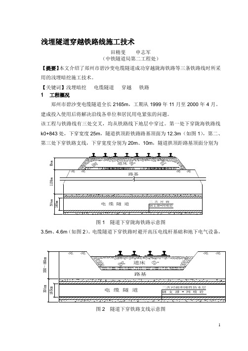
第一处下穿陇海铁路线k0+843处,下穿宽度25m,隧道拱顶距铁路路基顶面为12.3m(如图1),第二、第三处下穿铁路支线,下穿宽度分别为20m、10m,隧道拱顶距路基顶面分别为隧道下穿铁路线第一、第二处为正交,第三处为斜交67°。
隧道采用马蹄形断面,开挖断面宽2.79m、高3.04m,净空宽1.65m、高1.90m。
初支喷射混凝土厚250mm,稳定后施作二次衬砌(厚300mm),隧道内侧设刚性防水层厚20mm(如图3)。
2 工程地质与水文地质隧道下穿铁路线段工程地质为粉土,硬塑,含较大颗粒姜石,f=165Kpa,r=17.7KN/m3,C=10Kpa,φ=22°,Es=12Mpa,自稳能力非常强。
地下水埋置较深,隧道下穿地层无地下水。
3 施工方案的选择可供选择的方案有三种,即盾构法、顶管法和浅埋暗挖法。
3.1 盾构法盾构法施工中所采用的盾构是一种针对性很强、结构庞大的专用性设备,而不是通用设备。
700m以下的隧道采用此法是不经济的。
即使采用由中铁隧道局研制的简易的半断面插刀式盾构也需一定的制造时间,并且该段造价也会比一般地段大幅度增加。
3.2 顶管法顶管法是目前下穿铁路常用的施工方法,它是直接在松软土层中敷设中、小型管道的一种施工方法,它由顶进设备、工具管、中继环、工程管及吸泥设备组成。
采用此法施工需在铁路一侧开挖一工作坑,工作坑主要是安装顶进设备,承受最大的顶进力,因而要有足够的坚固性。
经考察,隧道下穿铁路线段均无可供开挖工作坑的地方。
遂道工程历史沿革

遂道工程历史沿革自英国于1826 年起在蒸汽机车牵引的铁路上开始修建长770米的泰勒山单线隧道和长2474 米的维多利亚双线隧道以来,英、美、法等国相继修建了大量铁路隧道。
19世纪共建成长度超过 5 公里的铁路隧道11 座,有3 座超过10公里,其中最长的为瑞士的圣哥达铁路隧道[1],长14998米。
1892年通车的秘鲁加莱拉铁路隧道,海拔4782 米,是现今世界最高的标准轨距铁路隧道,目前国内青藏铁路风火山隧道为世界海拔最高的单线铁路隧道。
在19 世纪60 年代以前,修建的隧道都用人工凿孔和黑火药爆破方法施工。
1861 年修建穿越阿尔卑斯山脉的仙尼斯峰铁路隧道时,首次应用风动凿岩机代替人工凿孔。
1867 年修建美国胡萨克铁路隧道时,开始采用硝化甘油炸药代替黑火药,使隧道施工技术及速度得到进一步发展。
在20 世纪初期,欧洲和北美洲一些国家铁路形成铁路网,建成的 5 公里以上长隧道有20 座,其中最长的瑞士和意大利间的辛普朗铁路隧道长19.8 公里。
美国长约12.5 公里的新喀斯喀特铁路隧道和加拿大长约8.1 公里的康诺特铁路隧道都采用中央导坑法施工。
其施工平均年进度分别为4.1 和4.5 公里,是当时最高的施工进度。
至1950 年,世界铁路隧道最多的国家有意大利、日本、法国和美国。
日本至20 世纪70 年代末共建成铁路隧道约3800座,总延长约1850公里,其中 5 公里以上的长隧道达60 座,为世界上铁路长隧道最多的国家。
1974年建成的新关门双线隧道,长18675 米,为当时世界最长的海底铁路隧道。
1981 年建成的大清水双线隧道,长22228 米,为世界最长的山岭铁路隧道。
连接本州和北海道的青函海底隧道,长达53850 米,为当今世界最长的海底铁路隧道。
20世纪60年代以来,隧道机械化施工水平有很大提高。
全断面液压凿岩台车和其他大型施工机具相继用于隧道施工。
喷锚技术的发展和新奥法的应用为隧道工程开辟了新的途径。
世界上最新的隧道是什么

世界上最新的隧道是什么圣哥达基线隧道,又译为哥达基线隧道。
建设用时17年,共耗资120亿瑞士法郎(约合110亿欧元)。
长约35英里(约合57公里),穿越瑞士阿尔卑斯山脉底部,距地面8000英尺(约2438.4米),已超过目前世界最长的隧道日本的青函隧道(全长约23公里),成为世界上最长与最深的隧道(含铁路隧道和公路隧道)。
隧道的试运行测试于2022年10月1日启动,2022年6月1日正式开通。
该项工程奇迹被视为欧洲团结的象征。
德国默克尔、法国总统奥朗德、意大利伦齐等欧洲主要国家领导人均应邀出席开通典礼。
世界上最新的隧道:地理位置圣哥达隧道位于海拔3000米的阿尔卑斯山区,连接北端的瑞士小镇埃斯特费尔德(Ertfeld)到南端瑞士小镇博迪奥。
世界上最新的隧道:施工单位瑞士联邦铁路(SBB-CFF-FFS)的全资子公司,阿尔卑斯枢纽方案圣哥达股份公司(AlpTranitGotthardAG)承担圣哥达山底隧道工程的建造。
世界上最新的隧道:工程背景圣哥达隧道由瑞士政府斥资建成,共花费103亿美元(约合661.5亿人民币),设计使用年限为100年。
实际上是两条平行的隧道,每条隧道都长达将近57公里,加上其他通道,这条贯穿瑞士阿尔卑斯山区的隧道总长达151.84公里穿越圣哥达山口(GotthardPa)的线路(隧道)是欧洲南北轴线上穿越阿尔卑斯山最重要的通道之一。
世界上最新的隧道:建设历程早在1947年,瑞士工程师格鲁纳就绘出了圣哥达基线隧道的设计草图,但受工程审批的繁文缛节、本钱高昂等因素影响,隧道建设直至1999年才开始。
该隧道开工后,分别从南北两端同时开始工作,2000多名工人开始参与到隧道的挖掘工作中,夜以继日地将3100吨山石挖出,这些石头超过了200万辆卡车的装载量,其中还有8名工人不幸遇难。
为了将施工时间缩短一半,承建商在工地开挖四条出入通道,以使隧道施工可以在5个不同地点(埃斯特费尔德(Ertfeld)、乌里州(Amteg)、塞德龙(Sedrun)、法伊多(Faido)和博迪奥(Bodio))同时进行。
- 1、下载文档前请自行甄别文档内容的完整性,平台不提供额外的编辑、内容补充、找答案等附加服务。
- 2、"仅部分预览"的文档,不可在线预览部分如存在完整性等问题,可反馈申请退款(可完整预览的文档不适用该条件!)。
- 3、如文档侵犯您的权益,请联系客服反馈,我们会尽快为您处理(人工客服工作时间:9:00-18:30)。
ResearchTunnel Engineering—ArticleThe Ceneri Base Tunnel:Construction Experience with the Southern Portion of the Flat Railway Line Crossing the SwissAlps Davide Merlini⇑,Daniele Stocker,Matteo Falanesca,Roberto Schuerch Pini Swiss Engineers,Lugano6900,Switzerlanda r t i c l e i n f oArticle history:Received5April2017 Revised11August2017 Accepted22September2017 Available online7April2018Keywords:Deep and long tunnelDifficult ground conditions Support designRisk managementTunnel monitoringLarge cavernsLow overburdenOverpass tunnelNumerical analysis Excavation in urban area a b s t r a c tThis paper summarizes the experience that was gained during the construction of the15.4km long Ceneri Base Tunnel(CBT),which is the southern part of theflat railway line crossing the Swiss Alps from north to south.The project consisted of a twin tube with a diameter of9m interconnected by cross-passages,each325m long.In the middle of the alignment and at its southern end,large caverns were excavated for logistical and operational requirements.The total excavation length amounted to approx-imately40km.The tunnel crossed Alpine rock formations comprising a variety of rock typologies and several fault zones.The maximum overburden amounted to850m.The excavation of the main tunnels and of the cross-passages was executed by means of drill-and-blast(D&B)excavation.The support con-sisted of bolts,meshes,fiber-reinforced shotcrete and,when required,steel ribs.A gripper tunnel boring machine(TBM)was used in order to excavate the access tunnel.The high overburden caused squeezing rock conditions,which are characterized by large anisotropic convergences when crossing weaker rock formations.The latter required the installation of a deformable support.At the north portal,the tunnel (with an enlarged cross-section)passed underneath the A2Swiss highway(the major road axis connect-ing the north and south of Switzerland)at a small overburden and through soft ground.Vertical and sub-horizontal jet grouting in combination with partial-face excavation was successfully implemented in order to limit the surface settlements.The south portal was located in a dense urban area.The excavation from the south portal included an approximately220m long cut-and-cover tunnel,followed by about 300m of D&B excavation in a bad rock formation.The very low overburden,poor rock quality,and demanding crossing with an existing road tunnel(at a vertical distance of only4m)required special excavation methods through reduced sectors and special blasting techniques in order to limit the blast-induced vibrations.The application of a comprehensive risk management procedure,the execution of an intensive surface survey,and the adaptability of the tunnel design to the encountered geological conditions allowed the successful completion of the excavation works.Ó2018THE AUTHORS.Published by Elsevier LTD on behalf of Chinese Academy of Engineering and Higher Education Press Limited Company.This is an open access article under the CC BY-NC-ND license1.IntroductionThe Ceneri Base Tunnel(CBT)is the southernmost portion of the New Railway Link through the Alps(NRLA)crossing the Swiss Alps from north to south[1].The client is the AlpTransit Gotthard Ltd., on behalf of the Swiss government.The NRLA is designed to create a continuousflat-rail connection from Basel to Milan,which will reduce travel times,increase the efficiency and sustainability of freight traffic,and connect Switzerland to the European high-speed railway network(Fig.1)[1].Along with the CBT,the main elements of the NRLA consist of the Lötschberg Base Tunnel (34.6km total length),which was constructed from1999to2006 and opened in2007,and the Gotthard Base Tunnel(57km total length),which was begun in1999and opened in December2016.The CBT is characterized by a twin tube system with a single-track railway tunnel with a length of15.4km linked through cross-passages that are spaced approximately325m apart (Fig.2)[1].The total excavation length amounts to approximately 40km and had an excavation volume of approximately4Â106m3. The cost of the works was about2.1billion Euro.The construction works started in1997with the drill-and-blast (D&B)excavation of the geological exploratory tunnel(3.1km in⇑Corresponding author.E-mail address:davide.merlini@(D.Merlini).Engineering4(2018)235–248 Contents lists available at ScienceDirectEngineeringlength),which was located approximately in the middle of the alignment (Sigirino).In 2008,an intermediate access adit (2.3km)—running almost parallel to the exploratory tunnel—was excavated using a gripper tunnel boring machine (TBM)(Fig.3(a)).Two large caverns (with a cross-section of about 270m 2)were excavated for logistical and operational reasons.The caverns were connected to the end of the intermediate access adit and of the exploratory tunnel.The excavation of the main tunnels started in 2010from the intermediate heading of Sigirino.The north (approximately 8.3km)and south (approximately 6.3km)tunnels were excavated simultaneously using D&B method (Lot 852,about 90%of thetotalFig.2.(a)Layout of the CBT [1]with photographs of (b)the north portal of Vigana (Camorino),(c)the intermediate heading of Sigirino,and (d)the south portal ofVezia.Fig.1.(a)The layout of NRLA project;(b)the profile of the Gotthard axis [1].236 D.Merlini et al./Engineering 4(2018)235–248excavation).The remaining portion of the tunnel was completed in backward driving lots at the north(Lot853)and south(Lot854) portals.In order to minimize the time and cost of construction,a total of eight excavation faces were operated simultaneously.The Sarèjunction caverns(Fig.3(b))are located in south of CBT and extend for a length of approximately400m.They are charac-terized by a variable geometry of the section,which consists of a conical pattern with a maximum cross-section of about260m2. At the end of the Sarèjunction caverns,there are two stub tunnels of approximately150m each,which will allow the construction of the future extension of the NRLA project through Italy.The excavation of the CBTfinished in March2015and January 2016with a breakthrough at the south and north portals,respec-tively.The civil works are currently under completion,and the installation of the railway infrastructure systems began in the summer of2017.The CBT is scheduled to be opened in2020.The cross-section of the CBT(Fig.4)has an excavation surface area of48–87m2and an optimized horseshoe shape[2].The shape is designed to meet the multiple requirements that result from the operational needs of the railway line,along with other require-ments related to the project execution and its geomechanical envi-ronment.A double lining is constructed along the entire CBT;the external lining provides temporary stability during construction,while the inner lining provides long-term stability for the tunnel for the entire project life(100years).The inner lining is mostly constructed using non-reinforced concrete,and is only reinforced over the tunnel portions that are characterized by poor geological conditions or geometrically com-plex zones(e.g.,connections with cross-passages).A drainage sys-tem is placed between the two linings and waterproofing is placed at the arch[3].Groundwater is collected from the lateral drains to a central drain,which evacuates the water toward the north portal.The inner lining was cast far from the excavation face.This allowed the rock mass to experience larger deformations;as a result,based on the ground response curve,this procedure reduced thefinal load on the inner lining(thus allowing a reduction in the thickness of the inner lining and in its reinforcement).Static vali-dations of the inner lining were systematically performed during construction,using the crosscheck information gained during excavation.2.Geological investigation campaign and geological conditions expected before excavationThe entire CBT is situated in the crystalline bedrock of the Southern Alps[4],as shown in Fig.5.The overburden of the tunnel varies from about10m to a maximum of850m.A detailed survey campaign with a total bored length almost equal to that of the main tunnel,and with single boreholes of lengths up to700m, was executed during the period1991–2008.Based on geological and geotechnical conditions,it was possible to distinguish and characterize47homogeneous sections in order to perform an assessment of probable risk scenarios[5],as shown in Fig.6.The lithostratigraphic units crossed by the tunnel can be divided into two areas:in the north,the Ceneri Zone(10.4km); and in the south,the Val Colla Zone(5km).The Ceneri Zone is primarily formed of gneiss and,to a lesser extent,of basic and ultra-basic rocks(e.g.,amphibolites and serpentinites)thathaveFig.5.Forecast geological longitudinal profile of theCBT.Fig.4.(a)CBT cross-section;(b)3D rendering of the completedCBT.Fig.3.(a)The gripper TBM used for the excavation of the Sigirino access adit;(b)the D&B excavation of the Sarèjunction caverns.D.Merlini et al./Engineering4(2018)235–248237all undergone considerable metamorphism (amphibolite facies).The whole area is also affected by complex tectonics,of which the main consequence is a high dip angle for the schistosity,litho-logical contacts,and axial plane folds.The Val Colla Zone also includes a series of paragneiss and orthogneiss,combined with intermediary basic rocks (hornblende schists).Above all,it is their structural geometry that sets these two areas apart.In the Val Colla Zone,the planar structures follow sub-horizontal trends,while they are more vertical in the Ceneri Zone.The interface between these two areas,which is 600m in thickness according to forecasts,is formed by the ‘‘Val Colla Line (VCL),”which is mainly composed of mylonites (fine-grained schists,often with a high mica content)resulting from intense pre-Alpine ductile deformation,probably dating back between 290million and 240million years.Diaclases run through the entire rock mass and the project crosses some fault areas (fragile Alpine tectonics,especially Insubric phase).Although the rock mass is covered by alluvial,detrital,fluvio-glacial,and glacial Quaternary sediments,the digging for the base tunnel only goes through loose materials in the areas around the north and south portals.During the construction works,only minor water inflows were expected and the permeability of the rock mass was found to be generally low.3.Excavation methodsThe excavation methods were based on the geological prognosis results and on other requirements such as the environmental impact,logistics,and the timing/investment ratio.Besides the two shorter conventional tunneling works at the portals,the main excavations were carried out from the underground cavern located at the intermediate heading of Sigirino.Based on extensive geolog-ical investigations,the final design phase was closed with a high confidence in the selected excavation methods of the CBT.To sum-marize these methods,TBMs were planned for the tubes (a single-shield TBM for the south direction and a double-shield TBM for the north direction),while D&B method was limited to a short connec-tion from the Sigirino access adit to the Val Colla Line,and the cross-passages.In the review phase of the final design,the excavation of the northern portion of the CBT by means of TBM was abandoned due to the high risk of shield jamming (estimated tunnel radial conver-gence up to 30cm)in correspondence to the fault zones (22fault zones,having a possible extent ranging from 10to 110m).For theexcavation of the southern portion,both TBM and D&B methods were tendered as possible excavation methods.For economic rea-sons,the contractor who was awarded the construction of the main tunnels (Lot 852)selected the D&B method for the excavation of the entire tunnel (this option was about 10%cheaper than the TBM option).The owner and the contractor mutually decided to use a highly mechanized D&B method using efficient and modern heading installations [6],as shown in Fig.7.Each installation was planned to lead financial and technical improvements and consists of a ventila-tion platform that can be moved independently,a heading platform,an invert platform,a crusher,conveyors,and a single-track suspen-sion rail [7].4.Rock support classesA total of 10standard rock support classes (see the cross-sections in Fig.8)were designed in order to deal with the geotech-nical conditions that were expected along the tunnel drive of the CBT.The rock support classes range from SPV 1to SPV 10;the SPV 1to 4classes are characterized by flat invert slab,frictional bolts,and shotcrete reinforced with fibers;the SPV 5and 6classes are characterized by curved invert slab,fully grouted bolts,shot-crete reinforced with mesh or fibers,and reinforcing ribs;and the SPV 7to 10classes are characterized by a pseudo-circular shape,radial and face injected bolts,shotcrete reinforced with mesh,and reinforcing ribs with yielding elements [8,9].It should be noted that the distance between the location of the rock support installation and the tunnel face depends on the rock support class;in general,the higher the rock support class,the smaller the distance between the rock support installation and the tunnel face.The rock support classes SPV 3-accelerated (SPV 3acc)and SPV 6A were conceived during construction;the stan-dard rock support class SPV 3acc is an intermediate classbetweenFig.6.Risk scenarios assumed in the design phase of theCBT.Fig.7.The highly mechanized D&B method used for the CBT excavation.238 D.Merlini et al./Engineering 4(2018)235–248SPV2and SPV3that allowed a faster advance rate(in particular toward the north),while SPV6A is characterized by the installation of Toussaint–Heintzmann(TH)ribs and a larger over-excavation. The larger over-excavation allowed larger rock mass convergences (15cm at the tunnel crown and23cm at the wall);this reduced the load on the lining,and thus decreased the need to install the heavier—and more time consuming—rock support classes SPV7 to10.Fig.9shows the daily advance rate and costs for each standard rock support class,as well as a comparison between the cumulated tunnel lengths of installed rock support classes as foreseen in the design phase and those installed during construction.Due to the encountered geotechnical conditions,the lighter rock support classes SPV1and2were not adopted during construction;the ‘‘medium-to-heavy”rock support classes(SPV4to10)were installed over the majority of the tunnel length.A selection of the most appropriate rock support is essential to ensure the safety of the construction works while complying with the project time schedule and costs(i.e.,minimization of the project risks).Theflow chart in Fig.10shows the phases of the decision-making process that were adopted for the CBT;this pro-cess was aimed at mitigating and managing risk scenarios while ensuring the optimal choice of rock supports,according to Ref.[10].The decision-making process involves the designer,the construction site manager,and the contractor.The six phases of the decision-making process shown in Fig.10 are described as follows:(1)Planning.This entails an interpretation of the geological survey(along the profile and from the surface),laboratory investi-gation results,previous monitoring data,and results of numerical calculations in order to evaluate the most probable risk scenarios.(2)Standard cross-section choice.This is based on the consid-erations of the design phase,and the standard cross-section is chosen.The choice is made in agreement with the designer,con-struction site manager,and contractor,and all the information relating to the excavation(i.e.,type and number of installed safety measures,risk scenarios encountered,tunnel advance length,etc.) is collected in the module for safety measures.(3)Excavation.This is performed according to the standard cross-section chosen.(4)Check of the correct standard cross-section chosen.This is done through interpretation of geotechnical survey and monitoring data.In the case of successful testing,it is possible to proceed with the selected standard cross-section.In the case of too-conservative or too-light supports,the standard cross-section must be updated.(5)Verification of structural safety and serviceability.If the standard cross-section is too light,leading to an increase in defor-mations and possible cracks in the concrete,etc.,the structural safety must be checked.If the structural safety is not compromised, advance work can continue with a new,stronger cross-section.If structural safety is not achieved,replacement actions and the installation of additional supports must be carried out before exca-vation can continue.The choice of rock supports is made in agree-ment with the designer,construction site manager,andcontractor. Fig.9.(a)Daily advance rate and costs forecasted;(b)comparison between the forecasted standard cross-section and the executedone.Fig.8.Standard cross-sections used for the CBT excavation and related risk scenarios.D.Merlini et al./Engineering4(2018)235–248239(6)Design and execution of replacement measures.The works must be performed in the shortest possible time while ensuring optimal safety conditions.Tunnel excavation can only continue once the replacement measures and installation of addi-tional supports are completed.During tunnel construction,the geological conditions ahead of the tunnel face were evaluated by means of systematic probe dril-ling.Core drilling was carried out only before entering known major fault zones.A detailed face mapping was carried out after each round length.5.The tunneling experienceIn general,the rock mass conditions that were encountered during the excavation agreed well with the ones expected in the design phase(based on the extensive survey campaign). However,due to the intrinsic complexity of a long and deep tunnel and the complex behavior of some rock formations, unexpected events occurred during excavation.The following sections describe the major challenges that were encountered during excavation.5.1.Squeezing conditions and strong asymmetric convergences in the intermediate heading of Sigirino and CBT northThe excavation of the logistics caverns and the neighboring CBT toward the north was performed within the Giumello gneiss (GiuG)formation,under a high overburden with maximum values of approximately800m.Using the two-dimensional(2D)distinct element code UDEC TM [11],the stress-strain behavior of the different types of rock mass encountered was evaluated.The main geological and geotechnical structures(joints,fault system,and disturbed zones)were defined on the basis of the forecast for each macro-structural area and on the basis of the geometrical characteristics(i.e.,tunnel direction and overburden).For the CBT excavation,according to the numerical results, maximum displacement would occur close to the fault zones and should amount to about10cm.Higher deformations than those predicted were observed during the excavation in the geological formation of GiuG[12]. Compared with the prognosis,the geological response of the rock mass showed behavior that was strongly influenced by the fault zones(i.e.,faults and shear zones formed by cataclasites of up to 1m thickness,or cataclasites with kakirite of up to20cm thickness)subparallel to the direction of excavation and to schis-tosity that significantly increased the structural anisotropy (Fig.11).The displacement monitoring performed by three-dimensional(3D)stations and multipoint extensometers showed high values of deformation of30–40cm for the CBT’s northwest advance.A strongly asymmetric pattern was found,with velocity values that were not assumed to decrease even at an outstanding distance from the face(Fig.12)[13].As a consequence,important cracks in thefirst lining occurred(Fig.12).To achieve an optimal understanding of the deformation behavior of the rock mass,sev-eral back-analyses[14]were performed using numerical calcula-tions(Fig.13).The latter allowed a correct validation of the mitigation measures as well as the redesign of thefirst lining and of the second lining.Due to the structural anisotropy of the rock masses,asymmetrical convergences frequently occurred dur-ing the excavations of the CBT north(leading to the local formation of cracks in the primary lining).The convergences were higher in the east side of the tunnel crown and in the west side of the tunnel wall.The asymmetric convergences required the installation of longer bolts(compared with the standard rock support classes) and/or the increase in the bolting density over15%–20%of the overall north CBT excavation.5.2.Excavation through a major fault zone under high overburden in CBT south:The Val Colla LineThe major fault zone that was expected and encountered during the CBT excavation is the so-called VCL[15,16],anintensely Fig.11.Geological plan of the study area.(a)Forecast;(b)crosscheck.NE:northeast;NW:northwest.Fig.10.Aflow chart for the choice of rock support class:①planning;②standardcross-section choice;③excavation;④check of the correct standard cross-sectionchosen;⑤verification of structural safety and serviceability;and⑥design andexecution of replacement measures.240 D.Merlini et al./Engineering4(2018)235–248tectonized zone with a length of 658and 529m in the east and west tubes,respectively.During excavation,the VCL was encoun-tered about 200m earlier than expected (Fig.14).The major issue related to the deviation between the geological forecast and the encountered geology was related to the higher overburden (approximately 450m instead of 350m),and thus to the higher stress state.The encountered rock mass formations were intensely tectonized,and were as follows:Formation 1a:an alternation of phyllites,mylonite,and mica schist;Formation 1b:gneiss;Formation 2:a heterogeneous mixture of lithotypes 1a and 1b with kakirite-type fault breccia and fault-gauge;and Formation 3:a kakirite-type fault-gauge.The most unfavorable geotechnical section—which consisted of alternating fault breccia and fault-gouge-type kakirite,mylonite,and cataclasite,which was several meters thick—was found over a length of about 250m.For the excavation of rock mass formations 2and 3,the SPV 7to 10cross-sections were adopted;these are characterized by a pseudo-circular shape,radial and face injection bolts,shotcrete reinforced with mesh and reinforcing ribs,and yielding support with the presence of slots.The combination of extremely poor rock mass conditions and high overburden led to strongly anisotropic deformations (peak values up to about 80cm,Fig.15),loosening and,finally,to a major face instability (about 150m 3of material).To overcome the sec-tion where the collapse occurred,piles,shotcrete reinforced with mesh,reinforcing ribs (type TH 29),and radial and grouted face bolts were installed (Fig.16).Analytical calculations were also performed in order to check the tunnel face stability (based on Ref.[17]).Over the remaining portion of the VCL,the encountered geotechnical conditions were more favorable than expected,as shown in Table 1.Fig.14.Geological plan of the study area:forecast (green)and crosscheck (red)VCL limits.Tm:tunnel meter used in CBT;ATKm:chainage in meter of the NRLAAlpTransit.Fig.13.(a)Back-analysis conducted using the 2D UDEC TM code;(b)replacement actions underconstruction.Fig.12.(a)Monitored displacements (unit:mm)in section NW9;(b)cracks in the first lining for the CBT’s northwest advance in the GiuG formation.D.Merlini et al./Engineering 4(2018)235–248241To achieve an optimal understanding of the deformation behav-ior of the rock mass,several back-analyses were performed using finite-element method (FEM)analyses.The latter allowed a correct validation of the mitigation measures as well as the redesign of the first and second linings [18].5.3.Excavation through a major fault zone under high overburden in CBT north:The Val Mara ZoneFor the north advance,the most critical geotechnical section was represented by the Val Mara Zone (VMZ).The VMZ was char-acterized by a length of about 150m,a maximum overburden ofabout 800m,and the widespread presence of kakiritic and cata-clastic levels embedded in mixed gneiss and intensively tectonized.In this section,as forecast in the design phase,the SPV 7to 10cross-sections were adopted;these are characterized by a pseudo-circular shape,radial and face injection bolts,shotcrete reinforced with mesh and reinforcing ribs,and yielding support with the presence of slots.During excavation,the VMZ was encountered approximately 140m (Fig.17)earlier than expected.The poor ground conditions led to strongly anisotropic deformations (with peak values up to 40cm)and finally to a face instability of 250m 3(Fig.18).Umbrella pipes,shotcrete reinforced with mesh,reinforcing ribs (type TH 29),and radial and face injection bolts were installed before restarting the excavation (Fig.19).Several back-analyses were per-formed using FEM calculations in order to check the external lining and the consequences on the inner lining;an analytical calculation was also performed in order to check the tunnel face stability (based on Ref.[17]).5.4.Excavation of large caverns under difficult rock mass conditions in CBT south:The SarèjunctionThe Sarèjunction,which is located in CBT south (Fig.2),is char-acterized by a twin tunnel system of 400m in length,a coneshape,Fig.15.(a)Radial deformations monitored in targets located in different cross-sections and different positions;(b)geomechanical model for the CBT east tube section between chainage 945and :central tunnel crown;CD:tunnel crown west side;CS:tunnel crown east side;PD:sidewall west side;PS:sidewall east side;MD:footing west side;MS:footing eastside.Fig.16.Cross-section SPV 10with yielding support and a pseudo-circular shape,as adopted for the VCL excavation.Table 1Comparison between rock mass formations and rock support classes as planned in the design phase and as built (VCL excavation southeast tube).Rock mass formationsDesign phase (total length =620m)As built (total length =658m)1a1b 231a 1b 23Section length 17%27%41%15%44%27%27%2%Cross-section typeSPV 7/8SPV 9/10SPV 4/6/7SPV7–10Fig.17.(a)Geological longitudinal section forecast;(b)crosscheck.HB:homogeneous geomechanical section.242 D.Merlini et al./Engineering 4(2018)235–248a 260m 2maximum cross-section area,and an overburden of 150m.At the end of Sarècaverns,there are two stub tunnels of approximately 150m each;these allow the excavation of the future extension through Italy,while minimizing the disturbance to the CBT.Based on core boreholes from surface,laboratory,and in situ investigation,gneiss and orthogneiss formations and two disturbed zones were forecast (Fig.20).Numerical calculation with a distinct element method code was implemented and a maximum displacement of 80mm was forecast;no problem was therefore expected on the external ring.In the execution,shortly after the first 80m of excavation,a strong anisotropic rock mass with a low dip angle sequence of layers consisting of cataclasticfault-rock alternating with schistose gneiss with better rock matrix characteristics was found [19].Compared with the analysis in the design phase,higher deformations and cracks in the first lining occurred during the full-face tunnel crown excavation (Fig.21).Through the back-analysis of massive deformation monitoring and geomechanical data gained from horizontal core boreholes,an accurate geomechanical model was built (Fig.22).With this new model,a comparative numerical analysis was performed with full-face tunnel crown excavation and with the tunnel crown exca-vated in sectors.From these results,it was decided to carry out the remaining excavation with the tunnel crown excavated in sectors (Fig.23).The supports installed comprised a shotcrete lining of 35cm reinforced with two mesh layers;unlike the design phase,injection bolts of 10m and 8m and lattice girders of four /32mm spaced 1.2m apart were adopted.Further analysis was made to excavate peculiar cross-sections of the twin tunnels that were separated by a rock pillar only 3m wide,corresponding with the terminal part of the Sarèjunction.The external lining for the stubs and the CBT tunnel consists of 25cm of shotcrete reinforced with fibers;unlike the design phase,injection bolts of 8m together with TH 25reinforcing ribs (spacing of 1m)were installed.The caverns were excavated with a mechanical method (i.e.,hammer)in order to minimize the effect of nearby excavations.Due to the supports installed and the excavation technique adopted,there were no significant cracks in the shotcrete lining and themaximumFig.18.(a)Photo of the tunnel face instability occurred in the VMZ;(b)interpretation of thecollapse.Fig.19.Cross-section SPV 10with yielding support and a pseudo-circular shape,as adopted for the VMZexcavation.Fig.20.(a)Forecast geological plan with study cross-section;(b)Sarè3predictive model with forecast displacements (unit:mm)calculated by the UDEC TM code.D.Merlini et al./Engineering 4(2018)235–248243。
