艾法斯推出i3920B数字无线电台综合测试仪
中波技术手册
《中波广播发射台理论基础与实践技术手册》介绍【作者】庄涛【出版社】光明日报出版社【索书号】 ISBN 978-7-5112—6624-8【字数】 488千字(427页)【馆藏地点】样本书库【定价】 120元内容简介《中波广播发射台理论基础与实践技术手册》一书,是专门为中波广播发射台站值机员、技术人员编写的一本实用书籍,目的是为提高中波发射台值机员的业务理论知识和实际操作技能,为技术培训、职业技术鉴定提供科学、规范的依据。
本书内容涵盖了中波广播发射台值机员及技术管理人员应知应会的理论性知识和实践性知识。
全书共十二个章节,分别是:广播发展简史、中波广播理论综述、中波发射台概况、电工电子技术、仪器仪表的操作、信号源系统、DAM全固态数字调制中波发射机、PDM中波发射机的原理与维修、天馈线系统、自动化监控系统、配电系统、发射台技术防护,以及发射台理论知识要点总结、中波发射台技术能手竞赛试题精选和中波专业术语名词解释等四个附录。
本书特点抛去了繁杂的理论赘述和计算公式,以分类、特点、方法为基本内容;注重内容的可操作性和实用性。
以够用为度,图文并茂,通俗易懂,便于自学,便于查询。
内容既有初级值机员应知应会的理论与实践知识,又有高级值机员应具备的解决复杂问题的理论与实践知识,更加符合中波台各层次值机员的认知水平,特别适合做中波台技术人员的培训教材使用(本书有配套教学PPT课件,需另购)。
作者简介庄涛,大专学历,高级工程师,从事自动化电气设备的安装与维修工作,有三十多年的基础电器维修实践经验,具有较强的实际操作动手能力。
一九九八年从部队转业到河南省潢川中波台工作,从事中波技术维护工作,先后发表过二十多篇中波发射相关技术论文。
自主研发或创新的DX系列全固态中波发射机故障查询系统、多路循环监听控制器、中波发射台信号源系统的整合等项目曾分获河南省广播电影电影电视局科技创新一、二、三等奖。
本书配套教学PPT课件为了配合中波值机员培训,本书各章节都有配套教学PPT课件,PPT课件的特点是清新、生动、信息量大,通过现代化多媒体投影仪实用,能够优化课堂教学,调动课堂气氛,增加学员的理解和记忆程度.彻底改变了“一本书、一支粉笔、一块黑板”单调的教学模式。
惠普LaserJet Pro MFP M329, M428-M429 保修和法务指南说明书
1 服务与支持 ............................................................................................................................................................................................... 1 HP 有限保修声明 .................................................................................................................................................................... 2 英国、爱尔兰和马耳他 ................................................................................................................................... 3 奥地利、比利时、德国和卢森堡 ................................................................................................................. 4 比利时、法国和卢森堡 ................................................................................................................................... 4 意大利 ..
EMI传导测试仪哪款比较便宜
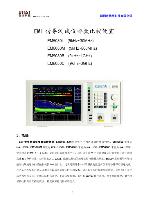
频率范围/MHz
0.15-0.5 0.5-5 5-30
限值/dBuV
准峰值(QP)
平均值(AV)
66-56
56-46
56
46
60
50
①绘制 QP 曲线 Limit Name 填入标准名称“EN55022”,单位选择 dBuV. 点选“QP”。 在 Freq 输入相应频率, Amplitude 输入限值,然后选择 Add ,也可以 Delete 删除,或者 Reset 全
选择所需标准并确定。如需添加新标准可参考”如何绘制标准曲线”。
选择补偿曲线。实际的应用中,在被测信号接入到接收机之前通常会有 LISN,天线,CDN,限幅器, 衰减器以及线缆等仪器设备,所以必须进行相关损耗补偿,可通过添加补偿曲线进行修正。如果没有 所需的补偿值可手动绘制补偿曲线,具体方法参考“如何绘制补偿曲线”。
12
深圳市优测科技有限公司
③绘制 PK 曲线 绘制 PK 曲线与绘制 QP 曲线方法相同。绘制完 PK 曲线点 Save。然后 Exit 曲线标准绘制完毕。例如
汽车电子 GB18655CISPR 25 L3 标准中有需要绘制 AV,QP,PK 三条曲线的。
绘制和调用补偿曲线
说明 复位软件到初始状态 在扫描运行过程中不要进行相关设置工作,在停止后进行设置 可以对扫描的数据进行编辑,包括峰值查找,添加和删除频点等 可以对数据表中的频点进行终测测试 快速生成检测报告 进入 Spot 模式,单点测量 返回上一级菜单
表 5:接收机软件主界面
接收机模式快速操作步骤
①Scan 扫描测试设置和测试
前置放大器开启
30MHz<f<1GHz,带宽 120kHz < 0dBμV
无线电综合测试仪使用攻略
实战综合测试仪—无线电综合测试仪使用攻略(上)类别:测试仪表阅读:884引言无线电综合测试仪是集多种射频仪器和常规电子测量仪器功能为一体的多功能仪器。
综合测试仪通常会集成有频率计、功率计、射频信号发生器、音频信号发生器、调制度计、信纳比仪、数字电压表、失真度计等常规功能,有的还具有频谱仪、示波器、接收机、跟腙信号源、信令分析、模拟基站、专用测试模式等高级功能。
由于综合测试仪功能多,往往一台仪器就能完成对讲机的发射和接收指标的检测和调校,所以它在业余无线电爱好者的心目中有很高的地位,颇有神兵利器的光环,很多业余无线电爱好者甚至认为,经过综合测试仪调整的二手对讲机就具有产品性能和质量的保证。
本文中,我们来了解一下它的功能及使用。
1.常见功能概述频率计:频率计数器可以测量发射机的载频实际频率,以了解载频误差。
不同制式的发射机对载频误差的要求是不同的,例如,常规FM调频对讲机频率偏差1 kHz问题不大,但是SSB单边带调制偏差2OOHz,声音就明显变调了。
综合测试仪的频率计功能与常规独立频率计相比多了自动误差计算功能,很多综合测试仪可以直接显示载频误差值,无需用户自己再做加减法,该功能对自动化测试和批量测试很有帮助。
此外,有的综合测试仪支持对一些特殊的TDMA时分多址信号,如GSM、TETRA、IDEN、MOTITHBO以及ODMA/WCDMA信号的频率计数,由于这些信号大多不是连续的,所以常规频率计无法对其直接测量。
射频功率计:综合测试仪的射频功率计功能类似终端式功率计(只能用于功率的测量,不能用来测量天线的驻波比)。
目前主流的综合测试仪都是程控数字化产品,所以功率计的测量结果也是直接数字读出的,并且可以选择W或dBm等常用单位,免除了用户换算之苦。
与传统指针式功率计相比,综合测试仪的数字功率计具有量程厂、读数方便、单位灵活的特点,尤其在小功率的测量万面,比指针式驻波比功率计的性能好得多。
此外,有的综合测试仪支持TDMA和ODMA信号的专项功率测量,这是常规通用功率计所不具各的功能。
利用AREOFLEX3920测试模拟对讲机

近年来,各地无线电管理部门陆续配备了许多先进的无线电检测装备。
如何发挥好这些设备的作用,将其运用到实际检测工作中,是无线电管理部门面临的重要课题。
青海省无线电监测站对如何利用A RE O FLE X3920综测仪测试模拟对讲机的各项性能参数进行解析,从而发现A R EO FLE X3920综测仪功能强、性能高,为无线电监测工作的开展带来便利。
工欲善其事,必先利其器。
A R E oFL Ex3920是美国艾法斯公司针对专业模拟和数字无线电通信生产的一款便携式综合参数测试仪表,该仪表支持调频、调幅和单边带制式的模拟无线电收发信机测试、也支持数字集群T ETR A、数字对讲机D M R,D P M R制式测试,频率范围高达2.7G H z,较好地满足了当前无线电发射设备检测工作的需要。
圆圈可卫西雹准备好与目标测试机相匹配的音频线、测试用射频电缆和测试射频接口连接器。
将音频线B N c接头一端接入仪表FcT N G E N,D E M oD接口,如音频线接口为非B N c接头,则需要选择相应的连接器进行转换后接入,另一头接入目标测试机音频输入接口。
射频电缆一头经过射频接口72l上海信息化连接器转接后,接入目标测试机的射频输出端,另一头接入仪表T/R端口。
为了操作方便,还可在仪表后面板usB接口上接入鼠标,将A R EoFLE x3920综测仪连接好电源线,将电源线接入交流稳压电源,再经过滤波后,方可接入市电。
最后,打开A R E oFLEx3920综测仪后面板上的电源开关,开启前面板绿色电源按钮,将目标测试机通电开机。
日可蚕圈测试载频输出功率、中心频率和频率误差。
载频输出功率是指发射机未调制射频信号提供标准输出负载的平均功率。
中心频率为发射机未加调制信号的实际输出载波中心频率。
频率误差是指测量载波频率和它的标称频率值间的差值。
步骤一:设置综测仪,使其进入模拟测试功能。
初次使用仪表时,待仪表白校完毕后,双击仪表屏幕右侧第二列的c onf i g键,此时仪表屏幕显示syS t em菜单,使用仪表操作面板右上方的导航控制键选择其后显示的子菜单A na l og D uP l eX,选中后单击仪表操作面板下方的Ent er键。
R8000B数字综合测试仪介绍
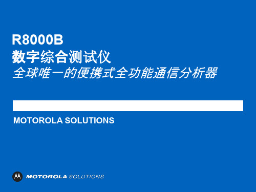
R8000B外观
•明亮的 8.4 英寸广视角 液晶显示屏 •一键式按键可以直接选择所 需的仪器 •用于高灵敏度接收机测量 的隐藏式天线 •可以快速方便地更 改 数字输入的调谐旋扭 : 模拟的感觉,数字的 精度
•方便使用的软 键操作
•热键可以支持快 速地 在屏幕之间导航
•退出键可让用户返回 到之前的屏幕,方便导 航
DMR发射机测试
发射机参数测试 ID号 色码 符号偏差 FSK偏差 幅度偏差 误码率测试
DMR发射机测试
DMR发射机测 试: 频谱显示图
功率包络图
DMR发射机测试
•发射机突发功率 测试:
•单时隙功率分布 •双时隙功率分布
DMR发射机测试
星座图
DMR 接收机测试
•接收机测试: •标准测试音,符合 0.153 (V.52或511) 1031单音信号 •静默信号 •1%误码率校准信号 •语音回放测试
R8000B 数字综合测试仪
全球唯一的便携式全功能通信分析器
MOTOROLA SOLUTIONS
R8000B架构概述
• 是基于软件架构的新一代无线电综合测试平台 • 多功能数字信号处理系统
• 硬件面对未来的新兴无线标准
• 现场升级快速增加协议和选件
安装自行操作无需返厂
• 基于PC的VGA、 USB和以太网接口
R8000B应用领域
政府机关
制造业
无线对讲生产 交通运输
无线电管理
公共安全
铁路交通 铁路
维修中心 对讲机维 修中心
能源行业
R8000B主要仪表功能
提供紧凑型轻量级解决方案。 全面的模拟和数字测试系统。
频谱分析器 射频信号发生器 高灵敏度测量接收机 交流/直流电压表 信纳表 失真观测仪 调制观测仪 音频示波器 频率误差计 FM 频偏观测仪 AM 调制观测仪 接收信号强度测量表 宽带和窄带功率计 音频计数器 音频信号发生器 电缆故障定位器(可选) 跟踪信号发生器(可选) 回波损耗/VSWR 桥(可选 DMR 测试模式(可选) DPMR测试模式(可选) NXDN 测试模式(可选) TETRA 用户测试模式(可选) P25 传统测试模式(可选) P25 中继测试模式(可选)
wifi 无线SIP电话机--飞音时代简介

产品性能
� 通过多家海外运营商的入网测试并取得批量应用,包括 KT (Korean Telecom), KCT, LG Telecom,SK Telecom等 � 优秀的语音质量和长时间 工作稳定性。
� � - G.729 PAMS value > 4.0 - G.711 PAMS value > 4.3
处理外销业务2009主力产品g501推出产品设计向mipscpu平台迁徙g501通过韩国移动运营商skt测试开始进入批量销售voip电话机产品ip300ip500获得韩国政府tta安全认证并开始进入批量销售飞音voipiad产品合计销售超过100万台北京飞音时代技术有限公司顺利通过国家高新技术企业复审2010推出无线voip解决方案包括支持无线的voipiad产品及wifiphone产品在深圳设立深圳爱斯瑞科科技有限公司负责硬件产品的设计及外协厂管理飞音voip终端产品进入印度市场2011voip电话机产品ip6xx系列ip652ip622ip542n推向市场并在俄罗斯批量应用韩国运营商kct定制ieee80211n无线路由器通过bmt测试开始批量销售支持wifi的桌面式voip电话ip542n获得市场青睐北京飞音时代获得第一份发明专利授权专利号
重点产品介绍-G502N
• 采用低成本的1T1R无线路由器芯片RT5350实现,CPU 内核为MISP24KEc 360MHz主频 • 支持2路 FXS 接口;满足双路同时工作时G.729 PESQ 大于4.0 • 综合性能高于CISCO 同类产品 SPA2102 • 得益于飞音强大的软件DSP设计能力,我们得以推出此款产品;此架构在1~2端口 IAD 设备上具有绝对性价比优势;
北京飞音时代技术有限公司
2012年版本 David Huang
N9320B频谱仪说明书
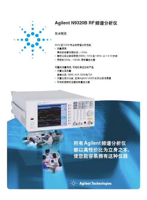
• 直接使用一键式功率测量功能, 进行通道功率、ACP、OBW、 SEM 和 TOI 测量。
• N9320B 可为自动测试程序提供 业界标准的 SCPI 语言支持和连通性 选择(USB 和 LAN)。与 Agilent ESA-L 系列兼容的 SCPI 代码能够 轻松地从 ESA-L 过渡到 N9320B。
• 频率计数器能更精确地读取频率 • U 盘可快速保存和调用测量结果
6
教育
无论您是要指导研究生完成重 要的科研项目,还是通过实验培养 的本科生的动手能力。安捷伦测试 设备将保证您能以最高标准培养未 来的工程师。
掌握测试仪器的使用方法和了解 RF 信号之间的相互作用是学好电子类 课程的基础,频谱分析是 RF 电路设计 的基础。它能使学生清楚地看到信号 交互和混频的过程。
Kensington 安全锁
TTL 触发 信号输入
USB 接口 LAN 端口
可上架安装
3U 高度 易于适应您的测试柜
3
电子制造
您要更快和更高性价比的射频分析工具来测试今天的消费类电子产品和元件需 — 不要再犹豫了!
无论您是制造无线鼠标、键盘、 GPS 设备或 RF 元件,如混频器,滤 波器或放大器,您都需要测量它们的 射频特性,以保证在其设计参数范围 (如频带宽度和输出功率范围) 内正常工 作。过小的射频功率会降低无线工作 距离,而过高功率会很快耗尽电池的 能量,从而缩短工作时间,同时还会 造成设备过热。
Agilent N9320B RF 频谱分析仪
技术概览
9 kHz 至 3 GHz 专业的频谱分析性能 • 测量速度:
星际音频JIB CT电缆测试器用户指南说明书

Table of Contents (1)Operation (2) (2)Connections (2)Select Test (2)Indications (3)Advanced Tests (3)Other Special Cables (4)Custom Cables (5)Warranty (7)Registration Card ...........................Back CoverIntroduction Battery InstallationIntroductionThank you for purchasing the Galaxy Audio JIB/CT Cable Tester. The CT is designed to test a wide variety of commonly used audio cables and quickly answer the question, “Is this cable good or bad?”A unique computer controlled circuit tests the cable 200 times per second, which allows the CT to detect and display intermittent problems that other cable testers fail to catch.The CT control panel simply consists of a rotary switch, one Green LED, and one Red LED. A quick reference chart is located on the bottom of the unit.TOP BOTTOMConnectors and Controls1Operation1. Battery Installation: Switch to OFF position. Remove the Battery Drawer and install a 9-volt alkaline battery, being careful to not pinch any of the wires when reinstalling the Drawer. Due to the low power consumption design and the Auto Shutoff feature, the battery life of a standard 9V alkaline should be over 100 hours. The Auto Shutoff feature switches off the CT after approximately 5 minutesof inactivity. To reset the CT after Auto Shutoff, simply rotate the switch to the “Off” position and then back to your previous setting. If the Red LED becomes too dim to see, replace the battery with a fresh 9V alkaline.2. Connections: Plug one end of the cable to be tested into the appropriate connector on the “A” side of the CT, and the other end of the cable into the “B” side. All of the connectors on the “A” side are duplicated on the “B” side except for the XLR jacks, where the “A” side has a Female XLR and the “B” side has a Male XLR. CAUTION: Do not connect the CT to any audio device or system. Damage may result to the CT and/or the audio device.3. Select Test: Rotate the switch to select the number of conductors within the cable.NOTE: For accurate results it is necessary to select the correct number of conductors within the cable under test. If in doubt, you may want to remove one of the connector covers to count the conductors emerging from the cable.The following chart lists the number of conductors found in commonly used audio cables. When speaking of 1/4” or 1/8” connectors, the terminology TRS (Tip, Ring, Sleeve) is used to describe the conductors as they appear on the plugs. A Mono cable (2 conductor) would use only the Tip and Sleeve (TS), while a Stereo or balanced cable (3 conductor) would use all three Tip, Ring, and Sleeve (TRS).24. Indications: As the Selector Switch is rotated from the OFF position, the Green LED will blink twice to indicate the CT is ready to test. The Red LED will then light momentarily to indicate the cable is being tested. If the cable fails the test, the Red LED will remain lit. If the cable passes the test, the Red LED will go out and the Green LED will light. At this point you may want to check for intermittent problems by flexing or wiggling the cable. Be aware that cables can become intermittent because of wiring problems or failure of the connector contacts. Any change in the LED indications, even if only momentary, means that the cable has an intermittent problem and cannot be relied upon.5. Advanced Tests: Most of the standard audio cables will test either Pass or Fail according to the indications described above. However, there are some alternative indications given for Pass and Fail for certain cables. The chart below describes some of these cables and what indications to expect.36. Other Special Cables: Male-to-Male or Female-to-Female XLR Cables: Use a known good adapter cable to “change the gender” of one of the cable ends by connecting it in series with the cable under test. Female TS or TRS connectors: Use a known good Male-to-Male cable to “change the gender” to Male by connecting it in series with the cable under test.47. Custom Cables. The CT is designed to test industry standard and commercially available cables and adapters. The CT may not give accurate results for cables wired otherwise.NOTES56ONE YEAR LIMITED WARRANTYThis warranty gives you specific legal rights, and you may also have other rights which may vary from state to state. This warranty is extended to the purchaser and to any purchaser from him/her for value.GALAXY AUDIO warrants the materials and workmanship of its products for a period of one year from the date of the original purchase.The following are not covered by the warranty:1. Damage to or deterioration of the exterior cabinet which occurs after delivery.2. Damage after initial delivery resulting from accident, misuse or neglect.3. Damage resulting from failure to follow instructions contained in the owner’s manual.4. Damage resulting from the performance of repairs by someone other than GALAXY AUDIO.5. Damage occurring during the shipment or delivery of any GALAXY AUDIO product to GALAXY AUDIO after initial delivery of the product to you.6. Damage to any GALAXY AUDIO product which has been altered, or on which theserial number has been effaced or removed.If your unit requires service, it must be returned, shipping charges prepaid to GALAXY AUDIO in the United States. (This warranty is not enforceable outside the U.S.) Please call or write GALAXY AUDIO, 601 E. Pawnee, Wichita, Kansas 67211, (316) 263-2852. We will then issue you to an RMA# (Return Merchandise Authorization) which will need to be applied to the returned item. Under no circumstances should you return your unit to the factory without receiving an RMA or written instruction to do so. If service is required, you must present the original or a copy of the bill of sale as a proof of date of purchase of your unit. Upon receipt of your unit for service, GALAXY AUDIO will repair or replace your unit as soon as possible, but in no event later than 30 days after the receipt of the unit. We will return the unit to you, shipping charges prepaid, provided the necessary repairs are covered by this warranty.IMPLIED WARRANTIES OF MERCHANT ABILITY AND FITNESS FOR PARTICULAR PURPOSE ARE LIMITED IN DURATION TO THE LENGTH OF THIS WARRANTY, UNLESS OTHERWISE PROVIDED FOR BY STATE LAW. GALAXY AUDIO’S LIABILITY IS LIMITED TO THE REPAIR OR REPLACEMENT, AT OUR OPTION, OF ANY DEFECTIVE PRODUCT, AND SHALL IN NO EVENT INCLUDE INCIDENTAL OR CONSEQUENTIAL DAMAGES OF ANY KIND. SOME STATES DO NOT ALLOW LIMITATIONS ON HOW LONG AN IMPLIED WARRANTY LASTS AND/OR DO NOT ALLOW THE EXCLUSION OR LIMITATION OF INCIDENTAL OR CONSEQUENTIAL DAMAGES, SO THE ABOVE LIMITATIONS AND EXCLUSIONS MAY NOT APPLY TO YOU.GALAXY AUDIO does not authorize any third party, including any dealer or Authorized Service Center, to assume any liability on behalf of GALAXY AUDIO or to make any warranty for GALAXY AUDIO.7GALAXY AUDIO601 E. PawneeWichita, KS 67211(316) 263-2852(800) 369-7768Fax: (316) 263-0642Specifications subject to change without notice. 8___________________________________________________________________N a m e ________________________P h o n e _____________A d d r e s s ________________________________________C i t y , S t a t e , Z i p ____________________________________e m a i l _______________________D e a l e r _______________________P u r c h a s e D a t e ________R e g i s t r a t i o nREGISTRATION CARDRegistration information is used ONLY by GALAXY AUDIO and will be kept strictly confidential.GALAXY AUDIO P.O. BOX 16285WICHITA, KS 67216-0285PLACE STAMP HERE。
CMS50 CMS52 无线电测试仪说明书

~ Applications
• Radiocom Tests • Portable and Handhr.ld Mobile • Phone Test
ForyouJ'local n,!;lrollix J'I'j}),(!I'oJlllllil'o 80(! II", /i"
ill th" hac!; of this r:(Jlok'M or oliisido till" U.S. (',,/I: '.s. 1~S03-(i27-Jfl33. iI1sirl" the 1 mil: 1-1J()()~42(i-2:!O().
Modulation frequency range (CMS52): f <8 MHz, DC to 10kHz; f ~8 MHz, DC to 20 kHz. (CMS50): 15 Hz to 10kHz. kB MHz.
IWCTT系列无线电流变比器传输器操作手册说明书

|IWCTT SeriesINDUSTRIAL WIRELESS CURRENT TRANSFORMER TRANSMITTERWhilst every effort has been taken to ensure the accuracy of this document, we accept no responsibility for damage, injury, loss, or expense resulting from errors or omissions, and reserve the right of amendment without notice.Information for usersThis equipment has been tested and found to comply with the limits for a Class B device, pursuant to part 15 of the FCC Rules. These limits are designed to provide reasonable protection against harmful interference in a residential installation. This equipment generates uses and can radiate radio frequency energy, and if not installed and used in accordance with the instructions, may cause harmful interference to radio communications. However, there is no guarantee that interference will not occur in a particular installation. If this equipment does cause harmful interference to radio or television reception, which can be determined by turning the equipment off and on, the user is encouraged to try to correct the interference by one or more of the following measures:•Reorient or relocate the receiving antenna•Increase the separation between the equipment and receiver•Connect the equipment into an outlet on a circuit different from that which the receiver is connected•Consult the dealer or an experienced radio/TV technician for helpCaution: To satisfy FCC RF Exposure requirements for mobile and base station transmission devices, a separation distance of 20cm or more should be maintained between the antenna of this device and persons during operation. To ensure compliance operation at closer than this distance is not recommended. The antenna used for this transmitter must not be co-located or operating in conjunction with any other antenna or transmitter. No other antenna may be used with this equipment other than the PCB antenna supplied with this equipment.This document may not be reproduced in any way without the prior written permission of the company.Cynergy3 Components Ltd7 Cobham Road, Ferndown Industrial Estate, WimborneDorset BH21 7PE, United KingdomTel:+44(0)1202897969,email:******************CONTENTS1.INTRODUCTION _______________________________________________________ 3 1.1 Safety Information________________________________________________________ 31.2Hardware Features_______________________________________________________ 32.UNPACKING__________________________________________________________ 43.PRODUCT IDENTIFICATION LABEL _____________________________________ 44.INSTALLING/CHANGING THE BATTERY________________________________ 45.SETTING UP THE IWT WIRELESS TRANSMITTER________________________ 56.TROUBLE-SHOOTING GUIDE__________________________________________ 77.SYSTEM PART NUMBERS______________________________________________ 88.SPECIFICATIONS______________________________________________________ 81. INTRODUCTION1.1 Safety InformationThis manual contains information that must be observed in the interest of your safety and to avoid damage to assets. Please read this manual before installing and commissioning the device and keep the manual in an accessible location for all users.Contains FCC ID: W70MRF24J40MDMECaution: To satisfy FCC RF Exposure requirements for mobile and base station transmission devices, a separation distance of 20cm or more should be maintained between the antenna of this device and persons during operation. To ensure compliance operation at closer than this distance is not recommended. The antenna used for this transmitter must not be co-located or operating in conjunction with any other antenna or transmitter. No other antenna may be used with this equipment other than the PCB antenna supplied with this equipment.Please see the Certifications section for more information on RF Exposure Compliance 1.2 Hardware FeaturesOur range of IWT wireless transmitters are available for a wide range of input types.The IWCTT Current Transformer Transmitter has been designed to accept an input from any mV AC output current transformer up to 500mVac and transmit the value to one of the IWR range of receivers.Please note that the IWCTT can also accept mV DC inputs up to a maximum of 0-500mVdcDepending on the receiver used, the value can be outputted as either a 4-20 mA or1-5 V dc signal, displayed and logged on a PC, output as a Modbus RTU or TCP/IP register, or transmitted to a remote server using MQTT messages. The range of receivers available is shown in the table below.Receiver Type FeaturesIWR-1 1 off 4-20 mA or 1-5 V and 1 off Relay OutputIWR-5 5 off 4-20 mA or 1-5 V and 1 off Relay OutputIWR-USB Connects to any PC for data display and loggingIWR-PORT Stores data from IWT transmitters as Modbus RegistersIoT-Gateway Stores data from IWT Transmitters & sends it to remoteservers using MQTT packetsThe IWCTT Current Transformer transmitter works within the ISM license-free 2.4GHz bands.Ranges of up to 500 m are possible using the standard transmitter and receiver unit with the optional 3dBi antenna giving a range of up to 750 m.The transmitter is powered by a primary 3.6 V lithium cell and care must be taken to insert the battery in the correct polarity.2.UNPACKINGThe instrument should be carefully inspected for signs of damage that may have occurred in transit. In the unlikely case that damage has been sustained, DO NOT use the instrument, but please retain all packaging for our inspection and contact your supplier immediately.3. PRODUCT IDENTIFICATION LABELThe unit delivered should be carefully inspected to ensure it is suitable for the application required. Detailed information on the product is included in the identification label and the user manual.Please ensure, in particular, that the input range of the IWT is suitable for the intended application and that the IWT unit will not be subjected to temperatures greater than those specified in this manual.4. INSTALLING/CHANGING THE BATTERYA Lithium 3.6V battery is included inside the IWT transmitter. The battery may be changed at any time, but care must be taken to install the battery with the correct polarity. After the battery has been changed, the unit should be switched on using the yellow slider switch SW3 and then the pushbutton SW1 should be pushed and held for 5s. This is to ensure the battery life count is reset correctly when a new battery is installed.The internal red LED will flash 5 times to indicate this procedure has been carried out successfully.The battery life is determined by the rate the transmitter sends the Temperature value to the receiver, this update rate can be selected using Dip Switch 1 and the default value is 10s.Please dispose of all batteries as specified by the legislator according to the Closed Substance Cycle and Waste Management Act or country regulations.! ! WARNING !MAKE SURE THE CORRECT BATTERY POLARITY IS OBSERVED!!! WARNING !INCORRECT BATTERIES MAY DAMAGE THE UNIT USE ONLY 3.6V LITHIUM C CELL BATTERIES5. SETTING UP THE IWT WIRELESS TRANSMITTERThe IWT instrument is shipped in a default configuration which allows the unit to connect with any default IWR receiver unit and transmit the measured signal every 10s simply by switching the unit on using SW3 on the internal circuit board.If a different update rate is required, or a different network frequency channel is required these parameters can be selected using DIP Switch 1 as detailed below:Switches 1, 2, 3 & 4 select the RF Network the IWT will transmit on. The default network for both the IWT transmitter and IWR receiver is network 1. RF NETWORK 1 2 3 4 1 0 0 0 0 2 0 0 0 1 3 0 0 1 0 4 0 0 1 1 5 0 1 0 0 6 0 1 0 1 7 0 1 1 0 8 0 1 1 19 1 0 0 010 1 0 0 1 11 1 0 1 0 12 1 0 1 1 13 1 1 0 0 14 1 1 0 1 15 1 1 1 0 16 1 1 1 1DIP SWITCHLED1BATTERYON/OFF Switch SW3SW1USB+Switches 5, 6 & 7 select the Transmission rate of the unit. This effectively sets how often the measured value is sent to the receiver.At 1 and 5 second rate, a power save option is available (on by default) that changes the transmit time to every 30 seconds if the IWR is switched off or out of range for more than 3 minutes. This option can be changed using the IWT-SET program.Transmit time 5 6 710 seconds 0 0 020 seconds 0 0 130 seconds 0 1 060 seconds 0 1 1120 seconds 1 0 0600 seconds 1 0 11 second 1 1 05 seconds 1 1 1Switches 8, 9, and 10 set the Channel Number of the transmitter. This is used with the 5 channel receiver unit (IWR-5) to select which IWT wireless transmitter is linked to which 4-20 mA or 1-5 V dc output channel.Channels 1 to 128 can be used with an IWR-USB, IWR-PORT, or IoT Gateway receiver. The channel number can be changed using the IWT-SET PC configuration software if switches 8, 9, and 10 are switched to the on position.Tx Channel Number 8 9 101 0 0 02 0 0 13 0 1 04 0 1 15 1 0 06 1 0 17 1 1 08 (or 1 to 128) 1 1 1The IWT transmitter is now set up and ready to be used. Install the unit where required, wire the appropriate input into the IWT as specified below (if there isn’t an integral sensor), and switch the unit ON using SW3. Pushbutton switch SW1 can be pushed to force the unit to transmit its current measured value. A red LED 1 will flash once when the transmit button is pressed and flash a second time if the transmission has been received and acknowledged by an IWR receiver unit.If the unit has transmitted successfully, the output of the connected receiver unit will output a value reflecting the signal level being measured.6.TROUBLE-SHOOTING GUIDEProblem encountered Possible CausesLED1 doesn’t flash when pushbutton SW1 is pressed Unit not switched on, switch on using SW3. The battery is not installed correctly.The battery needs replacing.LED1 only flashes once when SW1 is pressed IWR receiver not switched on. IWR receiver is not set up for the same RFnetwork.IWR receiver not within range of the transmitter.If an IWR-1 receiver is used, ensure that the transmitter is set to Tx Channel 1Output from the IWR receiver isn’t equivalent to the signal being monitored IWR receiver set up incorrectly, see IWR user manual for further details.Check that the green external LED on the receiver is flashing when the transmitter push button is pressed as the receiver may be out of range.7. SYSTEM PART NUMBERS8.SPECIFICATIONSPart Number Range Connection IWCTT50 0 - 50 mV ac 1. +ve 2. -ve IWCTT200 0 - 200 mV ac 1. +ve 2. -ve IWCTT330 0 - 330 mV ac 1. +ve 2. -ve IWCTT5000 - 500 mV ac1. +ve2. -veReceiver Part NumberNumber of Output ChannelsIWR-1 One IWR-5 FiveIWR-USB Data from up to 128 IWT Transmitters IWR-PORT Data from up to 128 IWT Transmitters IoT-Gateway Data from up to 128 IWT TransmittersIANT-33 dBi AntennaSystem PerformanceAccuracy (non-linearity & hysteresis) <± 1.0 % FSDSetting Errors Zero & Full Scale, <± 1.0% FSDInput rangeAc/dc mV From CT up to 0-500mV Ambient Temperature -20 to +80 °C Storage Temperature -20 to +80 °CWeight310 gRF TransmitterContains FCC W70MRF24J40MDME Power Requirements Lithium Thionyl Chloride C 3.6 V Cell Battery Life 5 Years (10s transmission rate)Dimensions 79 mm x 79 mm x 52mm (L x W x D)Mounting Any OrientationUnited States FCCThis equipment has been tested and found to comply with the limits for a Class B device, pursuant to part15 of the FCC Rules. These limits are designed to provide reasonable protection against harmful interference in a residential installation. This equipment generates, uses, and can radiate radio frequency energy, and if not installed and used in accordance with the instructions, may cause harmful interference to radio communications. However, there is no guarantee that interference will not occur in a particular installation. If this equipment does cause harmful interference to radio or television reception, which can be determined by turning the equipment off and on, the user is encouraged to try to correct theinterference by one or more of the following measures:•Reorient or relocate the receiving antenna•Increase the separation between the equipment and receiver•Connect the equipment into an outlet on a circuit different from that which the receiver is connected•Consult the dealer or an experienced radio/TV technician for helpWarning: Changes or modifications not expressly approved by Cynergy3 could void the user’s authority to operate the equipment.RF ExposureContains FCC ID: W70MRF24J40MDMEIn this equipment, the antenna supplied is a PCB antenna and an alternative antenna must not be used. Caution: To satisfy FCC RF Exposure requirements for mobile and base station transmission devices, a separation distance of 20cm or more should be maintained between the antenna of this device and persons during operation. To ensure compliance operation at closer than this distance is not recommended. The antenna used for this transmitter must not be co-located or operating in conjunction with any other antenna or transmitter. No other antenna may be used with this equipment other than the PCB antenna supplied with this equipment.Canada (IC)EnglishThis device complies with Industry Canada license-exempt RSS standard(s). Operation is subject to the following two conditions: (1) this device may not cause interference, and (2) this device must accept any interference, including interference that may cause undesired operation of the device.Under Industry Canada regulations, this radio transmitter may only operate using an antenna of the type and maximum (or lesser) gain approved for the transmitter by Industry Canada. To reduce potential radio interference to other users, the antenna type and its gain should be so chosen that the equivalent isotropically radiated power (e.i.r.p.) is not more than that necessary for successful communication. FrenchLe présent appareil est conforme aux CNR d’industrie Canada applicables aux appareils radio exempts de licence. L’explitation est autorisée aux deux conditions suivantes: (1) l’appareil ne doit pas produire de brouillage, et (2) l’utilisateur de l’appareil doit accepter tout brouillage, et (2) l’utilisateur de l’appareil doit accepter tout brouillage radioelectrique subi, même si le brouillage est susceptible d’en compromettre le fonctionnement.Conformément à la réglementation d’Industrie Canada, le présent émetteur radio peut fonctionner avec une antenna d’un type et d’un gain maximal (ou inférieur) approuvé pour l’émetteur par Industrie Canada. Dans le but de réduire les risques de brouillage radioélectrique à I’intention des autres utilisateurs, il faitchoisir le type d’antenne et son gain de sorte que la puissance isotrope rayonnée équivalente (p.i.r.e) ne dépasse pas l’intensité nécessaire à l’établissement d’une communication satisfaisante.| IWCTT SERIES WIRELESS CURRENT TRANSFORMER TRANSMITTER OPERATING MANUALC opyright © 2021 Sensata Technologies, Inc. Page 11 Sensata Technologies, Inc. (“Sensata”) data sheets are solely intended to assist designers (“Buyers”) who are developing systems thatincorporate Sensata products (also referred to herein as “components”). Buyer understands and agrees that Buyer remains responsible forusing its independent analysis, evaluation and judgment in designing Buyer’s systems and products. Sensata data sheets have been createdusing standard laboratory conditions and engineering practices. Sensata has not conducted any testing other than that specifically describedin the published documentation for a particular data sheet. Sensata may make corrections, enhancements, improvements and other changesto its data sheets or components without notice.Buyers are authorized to use Sensata data sheets with the Sensata component(s) identified in each particular data sheet. HOWEVER, NOOTHER LICENSE, EXPRESS OR IMPLIED, BY ESTOPPEL OR OTHERWISE TO ANY OTHER SENSATA INTELLECTUAL PROPERTY RIGHT, ANDNO LICENSE TO ANY THIRD PARTY TECHNOLOGY OR INTELLECTUAL PROPERTY RIGHT, IS GRANTED HEREIN. SENSATA DATA SHEETSARE PROVIDED “AS IS”. SENSATA MAKES NO WARRANTIES OR REPRESENTATIONS WITH REGARD TO THE DATA SHEETS OR USE OF THEDATA SHEETS, EXPRESS, IMPLIED OR STATUTORY, INCLUDING ACCURACY OR COMPLETENESS. SENSATA DISCLAIMS ANY WARRANTYOF TITLE AND ANY IMPLIED WARRANTIES OF MERCHANTABILITY, FITNESS FOR A PARTICULAR PURPOSE, QUIET ENJOYMENT, QUIETPOSSESSION, AND NON-INFRINGEMENT OF ANY THIRD PARTY INTELLECTUAL PROPERTY RIGHTS WITH REGARDTO SENSATA DATA SHEETS OR USE THEREOF.All products are sold subject to Sensata’s terms and conditions of sale supplied at SENSATA ASSUMES NO LIABILITYFOR APPLICATIONS ASSISTANCE OR THE DESIGN OF BUYERS’ PRODUCTS. BUYER ACKNOWLEDGES AND AGREES THAT IT IS SOLELYRESPONSIBLE FOR COMPLIANCE WITH ALL LEGAL, REGULATORY AND SAFETY-RELATED REQUIREMENTS CONCERNING ITS PRODUCTS,AND ANY USE OF SENSATA COMPONENTS IN ITS APPLICATIONS, NOTWITHSTANDING ANY APPLICATIONS-RELATED INFORMATION ORSUPPORT THAT MAY BE PROVIDED BY SENSATA. Mailing Address: Sensata Technologies, Inc., 529 Pleasant Street, Attleboro, MA 02703, USA.CONTACT US EUROPE +44 (0)1202 897969 ********************* Cynergy3 Components Ltd. 7 Cobham Road, Ferndown Industrial Estate, Wimborne, Dorset, BH21 7PE, United Kingdom USA +1 310 561 8092 / +1 866 258 5057 ********************* Europe The MRF24J40MD/ME wireless module used in this equipment has been tested and is in conformity with the essential requirements and other relevant requirements of the RED Directive 2014/53/EU. That module is in conformity with the following standards and/or other normative documents:Certification Standards Article Safety EN60950-1-2006 / A11:2009 / A1:2010 / A12:2011 / A2:2013(3.1(a)) Health EN 300 328 V2.1.1 / EN 62479:2010 (3.1(a)) EMC EN 301 489-1 V2.1.1 EN 301 489-1 V2.2.0 EN 301 489-17 V3.1.1 EN 301 489-17 V3.2.0(3.1(b)) Radio EN 300 328 V2.1.1 (3.2)。
艾法斯推出3920B数字无线电台综合测试仪

艾法斯推出3920B数字无线电台综合测试仪
阿纳海姆APCO国际20132013年8月艾法斯控股公司(Aeroflex Holding Corp,纽交所代码:ARX)旗下的全资子公司艾法斯有限责任公司(Aeroflex Incorporated)今日宣布推出全新的3920B数字无线电台综合测试仪,它适用于模拟AM和FM、数字P25、P25 Phase II、DMR、NXDN™、dPMR、TETRA和TEDS等技术。
3920B除了具有艾法斯3900系列无线电台综合测试仪上可提供的先进功能之外,还特别带有一个新的低相位噪声射频信号发生器。
3920B可以直接替换艾法斯3900系列的所有版本,其中包括之前的3901、3902和3920等型号。
3920B特有的这个新的低相位噪声射频信号发生器提供了改善的频谱纯度,其SSB相位噪音额定在10kHz偏移时的-110 dBc/Hz。
这种等级的性能是在来自载波的偏移量显着低于该类型规范20kHz的典型业界标准的情况下实现的。
3920B的这种能够实现接近于载波的、如此低的相位噪音规格的能力,使3920B成为当下数字窄带和模拟接收机测试的理想测试解决方案;对这两者而言,窄带相位噪音是至关重要的。
今天的窄带数字无线电台采用了异常灵敏的、同时也具有高性能的接收机。
这些新型数字无线电台常常提供优于-119 dBm的接收机灵敏度等级。
为了准确地测试这些接收机,了解用以测试灵敏度和选择度的发生器所具有的事故性相位噪音对接收机产生的不利影响是非常重要的。
诸如P25 Phase II。
利用AREOFLEX3920测试模拟对讲机
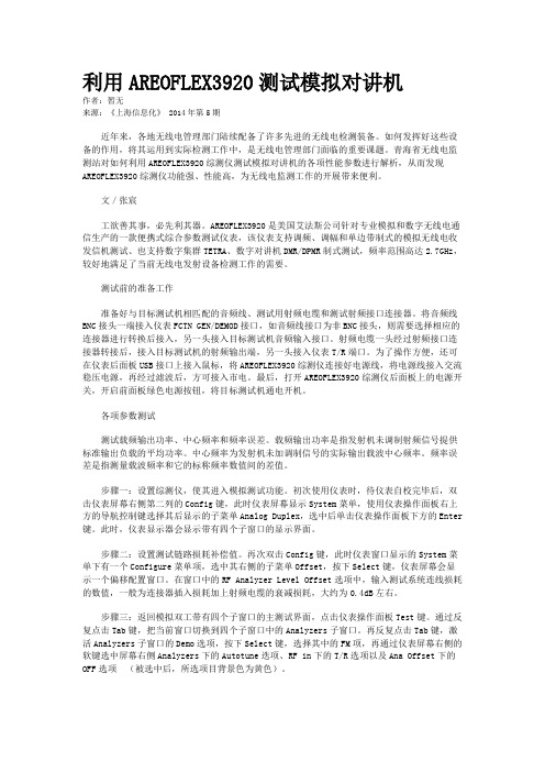
利用AREOFLEX3920测试模拟对讲机作者:暂无来源:《上海信息化》 2014年第5期近年来,各地无线电管理部门陆续配备了许多先进的无线电检测装备。
如何发挥好这些设备的作用,将其运用到实际检测工作中,是无线电管理部门面临的重要课题。
青海省无线电监测站对如何利用AREOFLEX3920综测仪测试模拟对讲机的各项性能参数进行解析,从而发现AREOFLEX3920综测仪功能强、性能高,为无线电监测工作的开展带来便利。
文/张宸工欲善其事,必先利其器。
AREOFLEX3920是美国艾法斯公司针对专业模拟和数字无线电通信生产的一款便携式综合参数测试仪表,该仪表支持调频、调幅和单边带制式的模拟无线电收发信机测试、也支持数字集群TETRA、数字对讲机DMR/DPMR制式测试,频率范围高达2.7GHz,较好地满足了当前无线电发射设备检测工作的需要。
测试前的准备工作准备好与目标测试机相匹配的音频线、测试用射频电缆和测试射频接口连接器。
将音频线BNC接头一端接入仪表FCTN GEN/DEMOD接口,如音频线接口为非BNC接头,则需要选择相应的连接器进行转换后接入,另一头接入目标测试机音频输入接口。
射频电缆一头经过射频接口连接器转接后,接入目标测试机的射频输出端,另一头接入仪表T/R端口。
为了操作方便,还可在仪表后面板USB接口上接入鼠标,将AREOFLEX3920综测仪连接好电源线,将电源线接入交流稳压电源,再经过滤波后,方可接入市电。
最后,打开AREOFLEX3920综测仪后面板上的电源开关,开启前面板绿色电源按钮,将目标测试机通电开机。
各项参数测试测试载频输出功率、中心频率和频率误差。
载频输出功率是指发射机未调制射频信号提供标准输出负载的平均功率。
中心频率为发射机未加调制信号的实际输出载波中心频率。
频率误差是指测量载波频率和它的标称频率数值间的差值。
步骤一:设置综测仪,使其进入模拟测试功能。
初次使用仪表时,待仪表自校完毕后,双击仪表屏幕右侧第二列的Config键,此时仪表屏幕显示System菜单,使用仪表操作面板右上方的导航控制键选择其后显示的子菜单Analog Duplex,选中后单击仪表操作面板下方的Enter 键。
2955B无线电综合测试仪
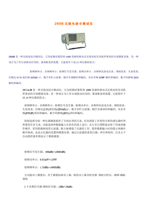
2955B无线电综合测试仪2955B是一种无线电综合测试仪,它包括测试量程到1000兆赫的移动式无线电收发讯机所要求的全部测量设备,是一种设计为工作台或移动应用的,紧凑配套的装置,它能看作下述14种仪器的组合:射频频率计,音频频率计,射频信号发生器,射频功率计,音频和直流电压表,调制度表,失真度表,信噪比(S/N)或信纳(SINAD)计,数字存贮示波器,顺序音调解码和编码,双音多频(DTMF)解码和编码,数字码静噪(DCS)解码和编码。
2955A/B是一种无线电综合测试仪,它包括测试量程到1000兆赫的移动式无线电收发讯机所要求的全部测量设备,是一种设计为工作台或移动应用的,紧凑配套的装置,它能看作下述14种仪器的组合:射频频率计,音频频率计,射频信号发生器,射频功率计,音频和直流电压表,调制度表,失真度表,信噪比(S/N)或信纳(SINAD)计,数字存贮示波器,顺序音调译码和编码,双音多频(DTMF)译码和编码,数字码静噪(DCS)译码和编码。
按钮选择为每一种仪器测量提供了全部必须的互连,从而消除了在利用分离的诸仪器时所需要的许多互连。
功能选择和数据输入在彩色码盘上进行,从左至右逻辑地安排了码盘的操作顺序。
采用阴极射线管示波器,极大地增强了仪器的工作,提供数据输入时的提示和操作顺序指南,也显示仪器的设置和测量结果,通过示波器的重复扫描,单次和保持,以及五个自动量程条形图显示了模拟测量。
射频信号发生器:400kHz~1000MHz射频功率计:0.05mW~150W射频频率计:1.5MHz~1000MHz全功能双工测量仪:用于测量标准双工器,跨段双工器及转发器调制分析仪:调频/调幅/调相2个音频信号源/调制信号源:10Hz~20kHz音频电压表:0V~100V(自动量程选择) 20Hz~50kHz(或DC方式) 音频频率计:20Hz~20kHz 50kHz数字存储示波器音频SINAD信纳比表音频S/N信噪比表音频DISTORTION失真度仪POCSAG编码器/DCS编码器DTMF、CCIR、EEA、EIA、ZVEI等编/译码器26个非易失存贮单元全部GPIB编程功能,可用于自动测试系统性能指针射频信号发生器频率:范围:0.4MHz~1000MHz分辨率:50Hz(≤530MHz); 100Hz(530MHz~1000MHz)指示:8位数字显示精度:与内频标准相同输出电平:范围:N型座:-135~-15dBm(0.04μV~40mV)BNC座:-115~+5dBm(0.4μV~400mV)单端双工:-140~-21.5dBm(0.0224μV~18.85mV)双端双工:-115~-15dBm(0.4μV~40mv)分辨率:0.1dB指示:4位数(dBm/μV, PD/EMF和dBmμV)精度:对高于-127dBm的电平为±2dB频谱纯度连续波调频:<30Hz(到520MHz) <60Hz(到1000MHz) (0.3~3.4kHz权重均方根值)典型值8Hz~250MHz, 15Hz~500MHz, 30Hz~1000MHz谐波:仅指在0.4~1000MHz频段内的谐波<-20dBc 到1.5MHz<-25dBc 1.5~250MHz<-20dBc 250~1000MHz分谐波:530MHz内没有,<-25dBc到1000MHz寄生信号:载频88MHz以上<-45dBc,低于110MHz,<-35dBc,高于110MHz,载频到1000MHz<-60dBc偏离20kHz的信噪比:<-106dBc/Hz到500MHz<-100dBc/Hz到1000MHz射频泄漏:小于0.2微伏电位降保护:N型座:反向功率过载时,荧屏上显示REMOVE RF INPUT (除去射频输入).同时听到机内喇叭的报警声。
综测仪测试NB-IoT-射频指标手册
综测仪测试NB-IoT-射频指标⼿册1⽂档综述1.1前⾔本⽂适⽤于使⽤综测仪对NB-iot 进⾏与模拟⼩区的连接及射频测试,当前版本。
1.2版本更新信息Signaling中添加DAU链接以及⽤户⾃定义调度。
Measurement添加RX测试功能。
可以建⽴NB-iot⼩区,并在Measurement中进⾏TX测试。
2 NB-iot Signaling2.1信令界⾯NB-iot SignalingNB-iot Signaling⼩区模拟界⾯需要License KS300才能打开,打开后界⾯如下图所⽰。
(打开⽅式,仪表⾯板上的SIGNAL GEN按键,选择NB-iot Signaling1)2.1.1连接状态Connection Status⼩区指⽰Cell,⼩区打开后会亮起数据包开关Packet Switched,⼩区打开后显⽰Cell on,终端进⾏⼩区搜索的时候显⽰Signaling in Progress,终端注册成功后显⽰Attached。
⽆线资源管理状态RRC state,终端未注册时显⽰Idle,终端注册成功后显⽰Connected。
2.1.2⽇志显⽰Event Log终端与仪表的信令交互情况,会显⽰在这个区域,如图中所⽰。
蓝⾊信息都是正常的提⽰,黄⾊信息为失败消息,红⾊信息为仪表出现错误。
终端信息UE Info及其他,暂未添加。
2.1.3⼩区设置Cell频带和双⼯⽅式选择,⽬前只⽀持FDD,后续版本将会⽀持TDD信道及频率选择Channel/Frequency,信道和频点有对应关系,设置⼀个参数的数值会相应变化。
窄带参考符号每资源元素功率NRS EPRE(Narrow Reference Symbol Energy per Resource Element),通过这个参数,可以设置仪表发射给终端的信号强度。
上⾏功率Uplink nominal power,设置终端上⾏的⽬标功率。
2.1.4连接Connection在Configuration中详解。
- 1、下载文档前请自行甄别文档内容的完整性,平台不提供额外的编辑、内容补充、找答案等附加服务。
- 2、"仅部分预览"的文档,不可在线预览部分如存在完整性等问题,可反馈申请退款(可完整预览的文档不适用该条件!)。
- 3、如文档侵犯您的权益,请联系客服反馈,我们会尽快为您处理(人工客服工作时间:9:00-18:30)。
[ 5 】 戴源, 等. T D — L T E 无线 网络规划与设计【 M] . 北京: 人民
邮电出版社 , 2 0 1 2 . ★
l | j |
鼍瓶 佘 _ 0l _ l
孙 春彬 :助理 工程 师 ,学士毕 业于青 岛 大学,现任 职 于 中国移 动通信 集 团 山 东有 限公 司青 岛分 公 司, 负责T I ) -
移 时的- 1 1 0 d B c / H z 。这 种等级 的性能是在来 自载波 的偏移量显著低于该 类型规 范2 0 k H z 的典型业界标准 的情况 下现 的。3 9 2 0 B 的这 种能够实现接近 于载波的 、如此低 的相 位噪音规格 的能力 ,使其成 为当下数字窄带和模
拟 接收机 测试 的理想 测试解 决方案——对 这两者而 言 ,窄带相位噪音 是至关重要 的。 “ 今天 的窄带数 字无线 电台采用 了异常灵敏 的同时也具 有高性能 的接收机 ,这 些新 型数 字无线 电台常常
▲ 工
DMR、N XDNT M 、d P MR、T E T R 和T E Ds 等技术 。3 9 2 0 B 除了具有艾法斯3 9 0 0 系列 无线 电台综合测试仪上 工可 提 供的先进功 能之外 ,还特别带 有一个新 的低相位 噪声射频信号发 生器。3 9 2 0 B 可以直接替换 艾法斯3 9 0 0 系列 的所有版本 ,包 括之 前的3 9 0 1 、3 9 0 2  ̄ H 3 9 2 0 等型号 。 3 9 2 0 B 特 有的这个新的低相位噪声射频信号发 生器提供 了改善的频谱纯度 ,其s s B 相 位噪音额定在1 0 k Hz 偏
作。
j
。 _ _ _ _ 艾法斯推出3 9 2 0 B 数字无线电台综合测试仪
艾法斯控股公司 ( A e r o l f e x H o l d i n g C o r p ) 旗下 的全 资子公 司艾法斯有限责任公 司 ( A e r o l f e x I n c o r p o r a t e d ) 日前 宣布 推出 全新 的3 9 2 0 B 数字 无线 电 台综 合 测试仪 ,它适 用于模 拟A MS  ̄ H F M 、数 字P 2 5 、P 2 5 P h a s e I I 、
秘戮; 2 0 1 3 中国国际信 息通信 展 专刊 ; i
标准进展 吁 ] _ 电信 网技术 , 2 0 1 0 ( 5 ) . [ 4 ] 王映民, 等. T D— L T E 技 术原 理与系统设计[ M】 . 北京 : 人 民邮电出版社 , 2 0 1 0 .
蔡 鹏: 中级工程 师 ,硕 士毕 业 于中 国 海 洋 大学 ,现任 职 于中 国移 动通信 集 团 山 东有 限公 司 青 岛分 公 司 , 负责
提 供优于 一 1 1 9 d B m的接收机 灵敏度等级 。为了准 确地测试 这些接收机 ,了解用 以测试灵敏 度和选 择度 的发生 器所具 有的事故性相位噪音对接收机产生 的不利影响是非常重要 的。诸 ̄ H P 2 5 P h a s e I I 这样 的数字技术采用 了相
位 调制技术 ( H— C P M ),因而任何 来 自于发生器 的附加 相位噪音都可 能导致错 误的测量结果 ,特 别是在采用 误码 率 ( B E 1 K)计算来确定接收机 的数据灵敏度时 。”艾法斯无线 电台测试 系统产 品营销 总监Ro b B a r d e n 说, “ 3 9 2 0 B 给测试工程 师和技术人 员树 立了信心 ,即即使在 具有过多相位 噪音的时候 ,测试 系统 并没有在他们 的
测量结果中诱发错误 。”
3 9 2 0 B 带 有前一代3 9 2 0 所有 的优异特性和功 能 ,这其 中包 括艾法斯 不断扩展 的Au t o — Te s t I I 功 能库 ,它们 可用于众多关键任务无线 电台 的自动测试与校准 。3 9 2 0 B 为Mo t o r o l a A P X M、Mo T t o r o l a XT S M T 和XT L M T 系列 ,以及 Ha r r i s 、E F J o h n s o n 、1 K e l m/ B K和Ke n wo o d 电台提供了A u t o — T e s t I I 功能 ,同时还支持 那些将在 不久 的将 来面 世的 各种新 无线电台 。 ( 本刊 )
L T E 网络 优 化 相 关 工 作 。
刘毅 : 工程 师 ,学 士 毕 业 于 山 东 大 学,现任 中国移动 通信 集 团山 东有 限 公 司T D — s c D M A / T D — L T E 项 目经理 ,负 责T D - S C D M A 与T D — L T E 规 划优化 相 关工
