systemverilog课件
systemverilog 可综合 语法

systemverilog 可综合语法-概述说明以及解释1.引言1.1 概述SystemVerilog是一种硬件描述语言,其可综合语法用于描述硬件设计的行为和结构。
可综合语法是指在编写SystemVerilog代码时,能够被综合工具翻译成底层硬件电路,并最终映射到FPGA或ASIC等可编程器件上的语法规则和风格。
因此,可综合语法在硬件设计中起着至关重要的作用。
在硬件设计中,可综合语法使设计工程师能够通过代码描述硬件的功能和结构,包括处理器、逻辑电路、存储器等。
通过使用可综合语法,设计工程师可以更加灵活地实现各种功能和性能要求,同时也能提高设计的可维护性和可重用性。
SystemVerilog的可综合语法特点是其结构化的设计风格,丰富的数据类型和内置的高级语言功能。
与传统的硬件描述语言相比,SystemVerilog提供了更多的抽象层次和编程特性,可以更高效地完成复杂的硬件设计任务。
例如,SystemVerilog支持面向对象的设计方法,可以使用类和对象对设计进行建模和封装。
此外,SystemVerilog还提供了多种数据类型和运算符,使设计工程师可以更方便地处理各种数据和信号。
综上所述,可综合语法在SystemVerilog中具有重要的地位和作用。
通过使用可综合语法,设计工程师能够更加方便地描述和实现各种硬件功能,提高设计的效率和可靠性。
在今后的硬件设计中,可综合语法的应用将更加广泛,并且不断发展和完善,以满足不断变化的设计需求。
1.2 文章结构文章结构部分的内容可以包括以下内容:文章结构的目的是为了给读者提供清晰的导航和理解文章的逻辑框架。
通过合理的结构,读者可以更好地理解文章的目的和内容,并能够有序地阅读和理解整个文档。
本文的结构如下:第一部分是引言部分,用于介绍文章的背景和相关信息。
在引言部分,我们将概述SystemVerilog可综合语法的定义和作用,并介绍本文的结构和目的。
第二部分是正文部分,主要内容是关于SystemVerilog可综合语法的定义和特点。
systemverilog class 参数

SystemVerilog 是一种硅设计与验证语言,其 class 参数在对象导向验证中具有重要作用。
本文将介绍 SystemVerilog 中 class 参数的相关知识,包括其基本概念、语法规则、应用场景以及实际案例分析,旨在帮助读者深入理解并灵活运用该特性。
1. 基本概念SystemVerilog 中的 class 是一种用户定义的数据类型,用于描述硅设计和验证中的对象与行为。
在 class 中,我们可以定义成员变量、成员函数、构造函数和析构函数等,从而实现面向对象的编程范式。
而class 参数则是class 中用于传递数据和控制行为的一种特殊成员变量,其具有一定的作用域和生命周期,可以在对象之间进行传递和共享,并在对象创建和销毁的过程中起到重要的作用。
2. 语法规则在SystemVerilog 中,class 参数的定义和使用遵循一定的语法规则,其基本形式为:```class my_class;// 成员变量int param1;string param2;// 构造函数function new(int p1, string p2);param1 = p1;param2 = p2;endfunction// 成员函数function void do_something();// 实现endfunctionendclass```在上述示例中,param1 和 param2 分别是 my_class 中的两个 class 参数,它们可以在构造函数中进行初始化,并在成员函数中进行操作。
3. 应用场景class 参数在 SystemVerilog 验证中具有广泛的应用场景,例如:- 传递验证环境配置参数:通过 class 参数,可以描述并传递验证环境中的配置参数,如时钟周期、数据宽度、协议类型等,从而实现灵活的验证环境定制。
- 控制验证对象行为:在验证对象的类定义中,可以使用 class 参数来控制对象的初始化、操作和销毁行为,实现对对象行为的灵活控制。
SystemVerilogveriflcation精品PPT课件
Verilog
System Verilog
It uses the “always” procedure to represent Sequential logic Combinational logic Latched logic
What is SystemVerilog?
System verilog is the superset of verilog It supports all features of verilog plus add on features It’s a super verilog additional features of system verilog will be discussed
1. Writing Testbenches using SystemVerilog - Janick Bergeron
2. Verification Methodology Manual - Janick Bergeron
3. SystemVerilog For Verification - Chris Spear
What is SystemVerilog?
What is SystemVerilog?
SystemVerilog is a hardware description and Verification language(HDVL) SystemVerilog is an extensive set of enhancements to IEEE 1364 Verilog-2001 standards It has features inherited from Verilog HDL,VHDL,C,C++ Adds extended features to verilog
systemverilog

systemverilogSystemVerilog语⾔简介1. 接⼝(Interface)Verilog模块之间的连接是通过模块端⼝进⾏的。
为了给组成设计的各个模块定义端⼝,我们必须对期望的硬件设计有⼀个详细的认识。
不幸的是,在设计的早期,我们很难把握设计的细节。
⽽且,⼀旦模块的端⼝定义完成后,我们也很难改变端⼝的配置。
另外,⼀个设计中的许多模块往往具有相同的端⼝定义,在Verilog中,我们必须在每个模块中进⾏相同的定义,这为我们增加了⽆谓的⼯作量。
SystemVerilog提供了⼀个新的、⾼层抽象的模块连接,这个连接被称为接⼝(Interface)。
接⼝在关键字interface和endinterface之间定义,它独⽴于模块。
接⼝在模块中就像⼀个单⼀的端⼝⼀样使⽤。
在最简单的形式下,⼀个接⼝可以认为是⼀组线⽹。
例如,可以将PCI 总线的所有信号绑定在⼀起组成⼀个接⼝。
通过使⽤接⼝,我们在进⾏⼀个设计的时候可以不需要⾸先建⽴各个模块间的互连。
随着设计的深⼊,各个设计细节也会变得越来越清晰,⽽接⼝内的信号也会很容易地表⽰出来。
当接⼝发⽣变化时,这些变化也会在使⽤该接⼝的所有模块中反映出来,⽽⽆需更改每⼀个模块。
下⾯是⼀个接⼝的使⽤实例:interface chip_bus;// 定义接⼝wire read_request, read_grant;wire [7:0] address, data;endinterface: chip_busmodule RAM (chip_bus io,// 使⽤接⼝input clk);// 可以使⽤io.read_request引⽤接⼝中的⼀个信号endmodulemodule CPU(chip_bus io, input clk);...endmodulemodule top;reg clk =0;chip_bus a;// 实例接⼝// 将接⼝连接到模块实例RAM mem(a, clk);CPU cpu(a, clk);endmodule实际上,SystemVerilog的接⼝不仅仅可以表⽰信号的绑定和互连。
电阻的system verilog描述
电阻的System Verilog描述一、引言电阻是电路中的基本元件,用于限制电流的大小。
在数字电路设计和模拟电路设计中,对电阻的准确描述和建模都至关重要。
System Verilog是一种硬件描述和验证语言,它结合了Verilog的硬件描述能力和一些高级的面向对象特性。
本文将介绍如何使用System Verilog 来描述电阻的特性和行为。
二、电阻的基本特性电阻的主要特性是其阻值,它决定了电阻对电流的阻碍程度。
欧姆定律描述了电阻、电压和电流之间的关系:V = IR,其中V是电压,I是电流,R是电阻的阻值。
在模拟电路中,电阻还可以表现出其他特性,如功率耗散和温度系数,但这些特性在数字电路设计中通常不是主要考虑的因素。
三、System Verilog描述电阻在System Verilog中,我们可以通过创建一个模块来描述电阻的行为。
模块是System Verilog中的基本构造块,用于封装硬件的功能和结构。
1. 模块定义首先,我们定义一个名为`Resistor`的模块,它有两个端口:`plus`和`minus`,分别代表电阻的两端。
```systemverilogmodule Resistor #(parameter real R = 1.0) (input wire real plus,output wire real minus);```在这个模块定义中,我们使用了`parameter`关键字来定义一个名为`R`的参数,它代表电阻的阻值。
这个参数的默认值是1.0欧姆。
2. 模块行为接下来,我们需要描述电阻的行为。
由于电阻是一个线性元件,其行为可以通过欧姆定律来描述。
在System Verilog中,我们可以使用连续赋值语句来描述这种行为。
```systemverilogassign minus = plus - (plus - minus) / R 1'b1;```然而,上面的语句实际上是一个错误的描述,因为它试图在一个连续的时间内解决一个方程,这在硬件描述语言中是不允许的。
system verilog semaphore
SystemVerilog信号量信号量是一种在多线程环境下常用的同步工具,它可以有效地控制多线程对共享资源的访问,保证线程间的互斥和同步。
在SystemVerilog中,信号量提供了一种方便的方式来实现多线程间的同步和互斥。
本文将介绍SystemVerilog中信号量的基本概念、语法和用法,并结合实际例子进行详细说明。
1. 信号量的概念在多线程编程中,当多个线程需要共享一个资源时,为了避免竞争条件和并发访问带来的问题,需要对这个资源进行同步和互斥控制。
信号量是一种经典的同步工具,它可以用来保护共享资源,防止多个线程同时访问,从而确保线程间的正确协调和合作。
2. SystemVerilog中的信号量在SystemVerilog中,信号量可以通过`semaphore`关键字来声明,它可以是计数信号量(counting semaphore)或二元信号量(binary semaphore)。
计数信号量允许指定多个线程同时访问共享资源,而二元信号量只允许一个线程访问。
信号量的声明语法如下所示:```systemverilogsemaphore sem = new(1);```其中,`sem`是信号量的实例名,`new(1)`表示创建一个初始值为1的二元信号量。
对于计数信号量,可以指定初始值大于1。
3. 信号量的使用在SystemVerilog中,可以使用`w本人t()`和`post()`方法来对信号量进行操作。
`w本人t()`用于申请信号量资源,如果信号量的值大于0,则减1并立即返回;否则,线程阻塞等待。
`post()`用于释放信号量资源,如果有线程在等待,则唤醒一个等待线程;否则,增加信号量的值。
下面是一个简单的信号量使用示例:```systemverilogsemaphore sem = new(1);task producer();w本人t(sem);// 生产者线程访问共享资源post(sem);endtasktask consumer();w本人t(sem);// 用户线程访问共享资源post(sem);endtask```在上面的示例中,生产者和用户任务分别通过`w本人t()`和`post()`来申请和释放信号量资源,确保了对共享资源的互斥访问。
Verilog的讲义52页PPT
0
0x
9
9.40ns
9
01
10
10.00ns 10
11
19
19.40ns 19
显示信号值 — $display
• $display输出参数列表中信号的当前值。 语法:$display([“ format_specifiers”,] <argument_ list>)
• $display输出时自动换行。
%m %t
hex octal decimal binary ASCII string strength module time
转义符
\t \n \\
\" \< 1-3 digit octal number> %0d
tab 换行 反斜杠 双引号 上述的ASCII表示 无前导0的十进制数
显示信号值—$write和$strobe
9.53ns
initial
10
01
begin
10 10.00ns 10
11
$display("time realtime20stime19\.t53ns
20
in1 \t o1 ");
10
$timeformat(-9, 2, "ns", 10);
$monitor("%d %t %d \t %b \t %b", $time, $realtime,
• $write与$display相同,不同的是不会自动换行。
$write($time, “%b \t %h \t %d \t %o \t”, sig1, sig2, sig3, sig4);
• $strobe与$display相同,不同的是在仿真时间前进之前的信号值。 而$display和$write立即显示信号值。也就是说$strobe显示稳定状态 信号值,而$display和$write可以显示信号的中间状态值。
system verilog 标准
系统Verilog是一种硬件描述语言(HDL),用于描述数字电路。
它包含了Verilog的所有特性,并添加了一些新的特性。
这些新的特性包括在设计中引入了数据类型的定义,更好地支持设计的抽象,以及更自然地支持设计的层次式描述。
在本文中,我们将深入了解System Verilog标准。
1. 介绍System Verilog标准System Verilog是IEEE标准1800,最初是由Accellera组织进行开发的。
它于2005年发行,是Verilog HDL的扩展,它添加了许多新的特性,使得它更适合于硬件验证和设计。
2. System Verilog的特性System Verilog添加了许多新的特性,以提高Verilog HDL的功能。
其中一些主要特性包括:a. 对象导向编程:System Verilog引入了面向对象的编程范式,使得设计和验证更加抽象和灵活。
b. 增强了数据类型和操作:System Verilog引入了更多的数据类型和操作,更好地支持设计和验证的需求。
c. 增加了随机性:System Verilog引入了随机性,使得验证更加全面和高效。
3. System Verilog在硬件验证中的应用System Verilog的特性使得它在硬件验证中应用广泛。
它提供了丰富的验证方法和工具,包括:a. 事务级建模(TLM):System Verilog提供了TLM的支持,使得验证更加抽象和高效。
b. Constrained随机验证:System Verilog引入了constrained random的验证方法,使得验证更加全面和高效。
c. Coverage驱动验证:System Verilog提供了coverage驱动的验证方法,使得验证更加全面和高效。
4. System Verilog在硬件设计中的应用除了在硬件验证中应用广泛外,System Verilog在硬件设计中也有着广泛的应用。
system_verilog教程

基于断言的验证技术SystemVerilog Tutorials下面的手册会帮助你了解一些SystemVerilog中最重要的新特点。
手册还提供了一些代码样本和例子使你可以对语言有更好"感觉"。
这些辅导假设你们已经了解了一些Verilog语言。
如果没有,你可以先去看看Verilog设计者指南(V erilog Designer’s Guide)。
* Data types* RTL design* Interfaces* Clocking* Assertion-based verification* Classes* Testbench automation and constraints* The Direct Programming Interface (DPI)SystemVerilog 的数据类型这个手册将描述Systemverilog新引进的数据类型。
他们大多数都是可以综合的,并且可以使RTL级描述更易于理解和书写。
整型和实型SystemVerilog引进了几种新的数据类型。
C语言程序员会熟悉其中的大多数。
引进新的数据类型构思是这样的,如果C语言和SystemVerilog有相同的数据类型可以使C语言算法模型更容易的转化为SystemVerilog模型。
Verilog的变量类型有四态:既是0,1,X,Z。
SystemVerilog引进了新的两态数据类型,每一位只可以是0或是1。
当你不需要使用的X和Z值时,譬如在写Testbench和做为for语句的循环变量。
使用两态变量的RTL级模型,可以使模拟器更有效率。
并且使用得当的话将不会对综合结果产生影响。
二态整型类型描述例子Bit user-defined size bit [3:0] a_nibble;Byte 8 bits, unsigned byte a, b;Shortint 16 bits, signed shortint c, d;Int 32 bits, signed int i,j;Longint 64 bits, signed longint lword;注意到和C语言不一样,SystemVerilog指定了一些固定宽度的类型。
SystemVerilog Assertions (SVA) EZ-Start Guide英文精品课件
SystemVerilog Assertions (SVA) EZ-Start GuideAugust 2006© 1995-2006 Cadence Design Systems, Inc. All rights reserved.Printed in the United States of America.Cadence Design Systems, Inc., 555 River Oaks Parkway, San Jose, CA 95134, USATrademarks: Trademarks and service marks of Cadence Design Systems, Inc. (Cadence) contained in this document are attributed to Cadence with the appropriate symbol. For queries regarding Cadence’s trademarks, contact the corporate legal department at the address shown above or call 800.862.4522.All other trademarks are the property of their respective holders.Restricted Print Permission: This publication is protected by copyright and any unauthorized use of this publication may violate copyright, trademark, and other laws. Except as specified in this permission statement, this publication may not be copied, reproduced, modified, published, uploaded, posted, transmitted, or distributed in any way, without prior written permission from Cadence. This statement grants you permission to print one (1) hard copy of this publication subject to the following conditions:1.The publication may be used solely for personal, informational, and noncommercial purposes;2.The publication may not be modified in any way;3.Any copy of the publication or portion thereof must include all original copyright, trademark, and otherproprietary notices and this permission statement; and4.Cadence reserves the right to revoke this authorization at any time, and any such use shall bediscontinued immediately upon written notice from Cadence.Disclaimer: Information in this publication is subject to change without notice and does not represent a commitment on the part of Cadence. The information contained herein is the proprietary and confidential information of Cadence or its licensors, and is supplied subject to, and may be used only by Cadence’s customer in accordance with, a written agreement between Cadence and its customer. Except as may be explicitly set forth in such agreement, Cadence does not make, and expressly disclaims, any representations or warranties as to the completeness, accuracy or usefulness of the information contained in this document. Cadence does not warrant that use of such information will not infringe any third party rights, nor does Cadence assume any liability for damages or costs of any kind that may result from use of such information.Restricted Rights: Use, duplication, or disclosure by the Government is subject to restrictions as set forth in FAR52.227-14 and DFAR252.227-7013 et seq. or its successor.SystemVerilog Assertions (SVA)EZ-Start GuideIn general, there are three components to efficient verification: stimulus generation, coverage, and checking. Cadence Design Systems, Inc. provides companion EZ-Start packages for each of these three areas. The focus of this EZ-Start package and its accompanying executable example is assertion-based verification (ABV). Specifically, dynamic ABV simulation using the SystemVerilog assertion language (SVA).This document is a self-guided introduction to using dynamic ABV and writing SVA. The following sections describe the three major steps involved in ABV:!Picking a focus area!Identifying behavior and mapping to property types!Implementing assertionsPicking a Focus AreaThe first step in ABV is to pick a focus area for your assertions. In general, you want to start with areas that are likely to contain bugs or that will benefit from additional visibility. For example, the following lists areas that typically have a good ROI for assertions and, therefore, represent good starting points for assertions.!Interfaces between blocks!Control logic that contains corner cases!Critical functions within the designNote: If the schedule permits, this list can be expanded to include other areas within the design.Identifying Behavior and Mapping to Property TypesAfter you choose a focus area, you can then identify interesting behavior within the focus area and then express them in natural language form. Once you have expressed the behavior in natural language form, you can map the behavior to various property types. A property is a description of the functional behavior of signals over time. An assertion states that a given property is an important aspect of the behavior of the design, and that the design must behave consistently with this property. Writing assertions starts with defining the properties of a design.The following table lists questions that can help identify the different types of properties in a design. Each of these questions map to a property type that can be used to create templates for your assertions.Table 1 Basic Questions and Property TypesQuestion Property TypeAre there signals that have a set behavior thatInvariantsmust occur independent of time?Bounded InvariantsAre there signals that have a set behavior thatmust occur within a certain time frame?Boundary CasesDoes the design contain boundary conditionsthat must trigger a set behavior?Bug IdentificationAre there ways to specify values or sequencesthat would describe an error condition?Signal ValuesIs the behavior of certain signals critical to thefunctionality of the design?Note: Although this set of questions is not exhaustive, it is a good starting point for developing assertions.The following sections describe each of these property types.InvariantsAn invariant is a condition that must always (or never) occur. Invariants are one of the easier property types to describe, because they do not involve time. Examples of invariants are:!One-hot signals!Boolean conditions that must always occur, or never occur!Special cases where an object must hold true, given a particular conditionBounded InvariantsA bounded invariant is a condition that must be invariant during a bounded period of time. Most often there are signals within the register transfer level (RTL) that can help identify this window of time. Otherwise, you can use auxiliary code to create a start and end signal that will identify this window and improve readability.Boundary CasesBugs often hide in boundary cases. You can develop an assertion that ensures a boundary condition produces the expected behavior.Bug IdentificationBug identification assertions describe behavior that must never occur in a design. The advantage of this type of assertion, opposed to describing behavior that must happen, is that RTL code does not get duplicated, which is usually a concern when you are writing RTL assertions.Signal ValuesOne of the most basic ways to describe a signal’s behavior is to identify when the signal:!Must have a value of 0 or 1!Transitions from 0 to 1, and from 1 to 0!Retains its current value!Changes valueIf this can be done without duplicating the RTL (or by a person other than the designer), then this is the most complete way to develop an assertion. This technique might be best for critical signals.Implementing AssertionsNow that you have selected your focus areas, extracted interesting behavior, translated that behavior into natural language form, and mapped the behavior to the various property types, you can express these property types in actual SVA syntax. Before doing this, you need to understand some basic SVA syntax.Basic SVA SyntaxThis section uses a sample Signal Value assertion to illustrate the fundamental SVA constructs.The following assertion is derived from the following natural-language statement: “If there is a rising edge on the request, then a grant must be issued within 1 to 3 cycles.”1. 2. 3. 4. 5. Figure 1 Sample Signal Value AssertionYou can then break down the example into the following:Assertion Label—Identifies the assertion. This is used for reports and debugging.(required)Directive— Specifies how the assertion is used during the verification process--as anassertion or constraint, or for collecting coverage information (required)Clocking—Indicates how or when the signals in the assertion are sampled (required)Disabling Condition—Disables the assertion during certain conditions (optional)Property Expressions (required)a. System Functions—Indicates one of the SVA system functions that are used toautomate some common operations. For example: $rose, $fell, $past, and$onehot. Refer to the “Writing SystemVerilog Assertions” chapter of the Assertion Writing Guide for information on the SVA system and sampled-value functions that are supported in the current release.b. Implication Operator ( |-> or |=>)—Specifies that the behavior defined on the right-hand side of the operator be checked only if the condition on the left-hand sideoccurs. There are two forms of the implication operator: overlapping (|->) and non-overlapping (|=>).The overlapping operator indicates that the last cycle of the LHS sequenceoverlaps the first cycle of the RHS sequence.The non-overlapping operator indicates that there is no overlap and that the firstcycle of the RHS sequence must occur one cycle after the LHS sequencecompletes.6.Note: When you are trying to capture an assertion in the standard written form,the implication operator typically maps to the word “then”.c. Cycle Operator (##)—Distinguishes between cycles of a sequence. Cycles arerelative to the clock defined in the clocking statement. Use a fixed number (##n) to specify a specific delay or a range operator (as specified in the next sub-bullet) to specify a range.d. Non-consecutive repetition operator ([*])—Enables the repetition of signals. Usethe form [*n] to represent a fixed repetition, or [*n:m]to specify a range ofrepetition from n to m. You can also apply the range operator to the cycleoperator.End of Statement Delimiter—Indicates the end of an assertion (required)Implementing Property TypesYou can leverage the syntax described in the previous section to create templates for each of the property types discussed earlier. The following table maps the different property types to SVA constructs that you can use in property expressions.Note: This table suggests SVA syntax that can be used in property expressions. This table does not cover the other aspects on an assertion, which were discussed in the previous section (such as assertion labels, directives, clocking, disabling conditions, and so on). Table 2 Property Types and SVA SyntaxQuestion Property Type Useful SVA SyntaxInvariant (onehot) $onehot(), $onehot0()Invariant (Illegal Combinations) ! (Boolean condition)Are there signals that are supposed to behave a certain way independent of time?Invariant (Special Cases) (special case) |-> (expected behavior) (special case) |=> (expected behavior)Are there signals that are supposed to behave a certain way within some window of time? BoundedInvariants(start) |-> ((!finish && cond)[*n:m] ##1finish && cond)(start) |-> ((!finish && cond)[*n:m] ##1finish)(start && !finish) |=> ((!finish &&cond)[*n:m] ##1 finish)Note: ##1 indicates a delimiter—not a 1-cycledelayAre there any boundary conditions in the design in which some behavior needs to be exhibited when that condition is reached? Boundary Cases (boundary case sequence) |-> (expectedsequence)Are there ways todescribe values orsequences that woulddescribe an errorcondition?Bug Identification Not (sequence)Are there signals that are critical to the functionality of the design? Signal Values (condition |=> $rose(sig))(condition |=> $fell(sig))(condition |=> sig == $past(sig))(condition |=> sig != $past(sig))Arbiter ExampleYou can now apply this ABV process to the arbiter example described in the Arbiter Specification,.which is included with this document. The arbiter example is typically a very good focus area for assertions, because it is control logic that often contains many corner case conditions.Mapping the BehaviorThe following lists arbiter example’s interesting behavior and maps this behavior to the various property types.Table 3 Arbiter Behavior MappingBehavior Property TypeGrant signals are zero one hot. InvariantOnce granted, the Busy signal must beasserted until Done.Bounded invariantThe arbiter must be fair for B. Boundary CasesYou must never see a GntB, when only ReqA is asserted.Bug IdentificationBusy must be asserted one cycle after agrant. Signal ValuesCreating the Assertion SyntaxAfter you map the behavior to a property type (Table 3), you can create the actual syntax for the assertion.! Invariant —Grant signals are zero one hot.assert_grant_zeroonehot : assert property (@(posedge clk) disable iff (!ResetN) $onehot0({GntA, GntB}));! Bounded invariant: Once granted, the Busy signal must be asserted until Done.assert_Busy_until_Done : assert property (@(posedge clk) disable iff (!ResetN) (GntA || GntB) |=> Busy[*0:$] ##1 Busy && Done); ! Boundary cases —The arbiter should be fair for B.assert_fair_for_B : assert property (@(posedge clk) disable iff (!ResetN)(GntA ##1 Busy[*0:$] ##1 Done&&ReqA&&ReqB |=> GntB));! Bug identification —You must never see a GntB, when only ReqA is asserted.assert_never_grant_wo_req : assert property (@(posedge clk) disable iff (!ResetN) not (ReqA && !ReqB ##1 GntB));! Signal values —Busy must be asserted one cycle after a grant.assert_Busy_active : assert property (@(posedge clk)disable iff (!ResetN) (GntA || GntB) |=> $rose(Busy)); Running the Assertions in the SimulatorUse the following steps to run these assertions in the Incisive Design Team Simulator:1. 2. 3. Go to the directory that contains the arbiter example:cd <example_install_dir>/iusUse the following command to run the example:run_simIn the console window, observe that the assertion –summary command shows that all the assertions have been executed, but one assertion fails.From the toolbar, click the Assertion Browser button . The Assertion Browserdisplays a flat list of all of the assertions in a design and provides the assertion’s name,4.5.6. module, instance, class, finished count, failed count, and so on. The assertions are listed in table format.Double-click any assertion. This displays the source code for the assertion. Notice how the assertions are embedded directly into the arbiter RTL file.Close the Source Browser.Select the assert_fair_for_B assertion. Add it to the waveform by selecting it and clicking on the Waveform button from the toolbar.Note: The waveform displays the state of the given assertion. The red circle indicates where the assertion fails and represents the starting point for debug.7. Using the steps discussed in this document and in the arbiter specification, you can addmore assertions to the <example install dir>/rtl/arbiter.v file and rerun.ConclusionThrough the course of this document, you have been exposed to an ABV process that uses SVA. This includes picking focus areas for assertions, identifying properties that are characteristic to the design, implementing assertions using SVA, and viewing assertions in a real example. After completing these steps, you can try implementing SVA in your own designs.。
systemverilog标准手册
SystemVerilog标准手册一、概述SystemVerilog是一种硬件描述和验证语言,它结合了Verilog HDL和VHDL的特性,并增添了许多新的功能和特性。
SystemVerilog的标准手册是SystemVerilog语言的权威参考资料,它详细说明了SystemVerilog的语法、语义和用法规范。
二、内容1. 语言基础SystemVerilog标准手册包含了SystemVerilog语言的基础知识,如数据类型、变量定义、控制结构、函数和任务等。
在这一部分,读者可以了解到SystemVerilog的基本语法和语言特性,为后续的学习和应用打下坚实的基础。
2. 对象和类SystemVerilog引入了面向对象的编程思想,允许用户定义自定义类型、类和对象。
SystemVerilog标准手册详细介绍了对象和类的定义、成员函数、继承和多态等相关内容,为用户提供了丰富的编程工具和技巧。
3. 验证方法SystemVerilog不仅可以用于硬件描述,还可以用于硬件验证。
SystemVerilog标准手册介绍了SystemVerilog的验证方法和工具,包括assertion、coverage、constrained randomization等内容,帮助用户编写高效且可靠的验证代码。
4. 高级特性除了基本的语言特性外,SystemVerilog还提供了许多高级的功能和特性,如接口、多线程、并发控制等。
SystemVerilog标准手册深入介绍了这些高级特性的用法和原理,帮助用户更好地理解和应用SystemVerilog语言。
5. 应用实例除了语法和特性的介绍外,SystemVerilog标准手册还提供了大量的实际应用示例,包括硬件描述、验证代码和仿真模型等。
这些应用实例可以帮助用户更直观地了解SystemVerilog语言的实际应用场景,加深对SystemVerilog的理解和掌握。
三、重要性SystemVerilog标准手册是学习和使用SystemVerilog语言的重要参考资料。
第四章 Verilog基本语法(一)PPT教学课件

2020/12/11
玉溪师范学院
参数
➢ 参数是一个常量。用parameter定义一个标识符来代表 一个常量。参数经常用于定义时延和变量的宽度。
格式: parameter param1 = const_expr1,
param2 = const_expr2,
…,
paramN = const_exprN;
assign #XOR_DELAY S=A^B;
assign #AND_DELAY C=A&B;
endmodule
19
TOP HA
2020/12/11
玉溪师范学院
参数值的模块引用
module TOP3(NewA,NewB,NewS,NewC); input NewA, NewB; output NewS,NewC; HA #(5,2) Ha1 (NewA, NewB, NewS, NewC);ut
selb
26
2020/12/11
玉溪师范学院
reg型
寄存器是数据存储单元的抽象 reg型数据常用来表示always块内的指定信号,常代表触
发器 reg型数据用initial或者always块中指定信号 reg型数据的缺省值是x。可以被赋正值或者负值。当它作
为一个表达式中的操作数时候,作为无符号数。 reg数据类型定义格式为
2.0 ; -0.1等
科学记数法,例如:
235.1e2 等于23510.0
234_12e2
等于2341200.0
实数小数通过四舍五入被隐式地转换为最相近的整数。例如:
42.446, 42.45 转换为整数42
92.5, 92.699 转换为整数93
-5.62 转换为整数-6
systemverilog 介绍

SystemVerilog是一个硬件描述语言,用于设计和验证数字系统。
它扩展了Verilog语言,提供了更多的建模能力和验证功能。
在本文中,我将全面介绍SystemVerilog,包括其语言特性、应用领域、优势和未来发展方向。
1. SystemVerilog的语言特性SystemVerilog是一种功能强大的硬件描述语言,它具有以下主要特性:a. 增强的数据类型:SystemVerilog引入了新的数据类型,如bit、logic、byte、int等,使得建模更加灵活和精确。
b. 增强的建模能力:SystemVerilog支持面向对象的建模,包括类、继承、多态等特性,使得设计描述更加直观和模块化。
c. 验证功能:SystemVerilog集成了Assertion语法和Coverage语法,支持设计验证和仿真覆盖率分析,能够更好地检测设计中的错误和缺陷。
d. 接口和连接:SystemVerilog引入了接口和连接功能,方便多模块之间的通信和连接,提高了设计的灵活性和可扩展性。
2. SystemVerilog的应用领域SystemVerilog被广泛应用于数字系统的设计和验证领域,包括但不限于:a. ASIC设计:SystemVerilog可以用于ASIC设计的RTL建模和验证,帮助设计人员快速构建和验证复杂的数字电路。
b. FPGA设计:SystemVerilog支持FPGA设计流程,可以用于FPGA逻辑综合和验证,满足不同规模和复杂度的FPGA设计需求。
c. 验证环境:SystemVerilog的验证功能使其成为验证工程师的首选语言,用于构建全面的验证环境和测试套件。
3. SystemVerilog的优势相比于传统的Verilog语言,SystemVerilog具有如下优势:a. 模块化和面向对象:SystemVerilog的面向对象建模使得设计更加模块化和可重用,提高了设计的灵活性和效率。
b. 验证功能:SystemVerilog集成了验证功能,提供了更多的验证手段和工具,有助于提高设计的质量和稳定性。
systemVerilog快速入门PPT
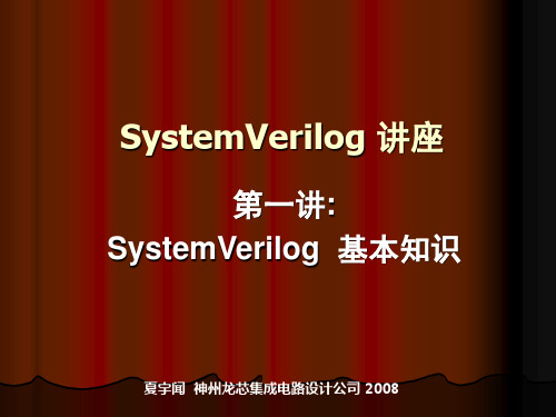
// 4态,Verilog-2001(位宽可变)数据类型 //4态,Verilog-2001(32位)有符号数据类型 //4态,(位宽可变) 0,1,x,或者 z //2态,(位宽可变) 1位 0 或 1 //2态,(8位)有符号整型数 //2态,(16位)有符号整型数 //2态,(32位)有符号整型数 //2态,(64位)有符号整型数
极大地提高了仿真速度
仅一种语言就能解决设计和测试问题
Co-sim HDL Simultion Overhead
testbench
使得我们有可能使用更 高速度的仿真工具,加 速了设计的完成
SystemVerilog
testbench
设计和验证语言的统一提高了设计效率,学习周期 设计和验证语言的统一提高了设计效率, 很短,设计和验证人员都乐意采用: 很短,设计和验证人员都乐意采用: 可自动生成高级的受约束-随机测试信号语句, - 可自动生成高级的受约束-随机测试信号语句,大 大降低了设计和验证的复杂度; 大降低了设计和验证的复杂度; - 完整的统一的断言技术改善了设计小组和验证小 组之间的交流。 组之间的交流。
SystemVerilog 是Verilog-2001扩展后的超集 扩展后的超集
---------------------------------- Verilog -2001 -------------------------------
ANSI C style ports standard file I/O (* attributes *) generate $value$plusargs configurations localparam `ifndef `elsif `line memory part selects constant functions @* variable part select
systemverilog 语法

systemverilog 语法SystemVerilog是一个硬件描述语言(HDL),它具有一些基本语法结构,与其他编程语言并无差异。
本文将介绍常见的SystemVerilog 语法。
1. 模块声明SystemVerilog使用模块来描述电路的结构,其中包含了输入端口、输出端口以及内部信号。
下面是一个简单的模块声明示例:module my_module(input input_port, output output_port);// Verilog代码在这里endmodule2. 变量声明变量可分为多种类型:- 整型变量(int):用于整数值。
- 浮点型变量(real):用于浮点值。
- 位变量(bit):只能存储0和1。
- 向量型变量(vector):用于存储多位的值。
下面是声明一个整型变量的示例:int my_variable;3. Control FlowSystemVerilog支持条件和循环语句,使得描述一些分支判断或循环的电路的时候变得更加直观。
- if/else语句:if语句用于条件分支,else语句用于指定当条件不满足时的操作。
下面是if/else语句的基本形式:if (condition) begin// 操作一endelse begin// 操作二end- for循环:for循环让您可以重复执行某些操作,直到满足指定的条件。
下面是for循环语句的一般形式:for(initialization, condition, increment) begin// 操作end其中,初始化指定循环计数器的值,条件指定循环何时结束,增量指定每次循环计数器自增的值。
4. 综合测试(assertions)综合测试是一种在设计中添加的指令,通过检查某些条件是否满足来确保设计的正确性。
可以使用综合测试指令对电路进行严格测试。
下面是一个简单的综合测试指令:assert(signal1 == signal2) else $display("Error");这里的断言语句表示,如果信号signal1不等于信号signal2,则显示错误消息。
systemverilog结构体使用方法
systemverilog结构体使用方法### SystemVerilog结构体使用方法#### 导语SystemVerilog作为硬件描述语言Verilog的扩展,增加了许多面向对象编程的特性,其中结构体(struct)是SystemVerilog中重要的数据类型之一。
结构体允许我们将不同类型的数据项组合成一个单一的数据类型,这对于组织和封装模块间的数据通信非常有益。
下面将详细介绍SystemVerilog中结构体的使用方法。
#### 结构体的定义在SystemVerilog中,你可以通过`struct`关键字来定义一个结构体。
结构体定义通常放在模块的外部,作为一个数据类型来使用。
```systemverilogstruct {bit [3:0] a; // 4位无符号整数logic [7:0] b; // 8位逻辑类型real c; // 实数类型} my_struct_t; // 结构体类型名称```在上面的例子中,我们定义了一个包含三个成员的结构体`my_struct_t`,它有一个4位的无符号整数`a`,一个8位的逻辑类型`b`,以及一个实数类型`c`。
#### 结构体的声明与初始化一旦定义了结构体类型,你就可以像声明其他变量一样声明结构体变量,并进行初始化。
```systemverilogmy_struct_t var1; // 声明结构体变量initial beginvar1 = "{default: 0}; // 初始化所有成员为0var1.a = 4"b1010; // 单独设置成员a的值var1.b = 8"b11001100; // 单独设置成员b的值var1.c = 3.14; // 单独设置成员c的值end```使用大括号`{}`可以进行结构体成员的初始化,`default: 0`表示所有未指定的成员都会被初始化为0。
#### 结构体数组SystemVerilog还支持结构体数组,这对于创建复杂的数据结构非常有用。
systemverilog方波

systemverilog方波
SystemVerilog是一种硬件描述语言,用于硬件设计和验证。
在SystemVerilog中,我们可以使用多种方法来生成方波信号。
下
面我将从生成方波信号的几种常见方法来回答你的问题。
第一种方法是使用always块和if语句来生成方波信号。
我们
可以在always块中使用if语句来检查计数器的值,并在特定的计
数值上切换方波信号的状态。
例如,当计数器的值大于一定阈值时,我们可以将方波信号置为高电平,否则置为低电平。
这种方法适用
于生成简单的方波信号。
第二种方法是使用时钟分频器来生成方波信号。
时钟分频器可
以将输入时钟信号分频为较低频率的时钟信号。
通过适当的配置,
我们可以将输入时钟信号分频为50%占空比的方波信号。
这种方法
适用于需要精确频率和占空比的方波信号。
第三种方法是使用计数器和比较器来生成方波信号。
我们可以
使用计数器来计数时钟周期,并将计数器的值与设定的阈值进行比较。
当计数器的值小于阈值时,输出低电平,否则输出高电平。
这
种方法适用于需要灵活控制方波频率和占空比的情况。
除了以上提到的方法,还可以使用状态机、PWM调制等技术来生成方波信号。
总的来说,根据具体的应用场景和需求,我们可以选择合适的方法来生成SystemVerilog中的方波信号。
希望以上回答能够满足你的需求。
verilog system函数
在Verilog中,`system`函数用于执行一个系统任务或调用一个系统函数。
它通常用于执行那些需要与外部环境交互的操作,例如读取或写入文件、与网络通信等。
`system`函数的一般语法如下:
```verilog
result = system("command");
```
其中,`command`是要执行的外部命令或系统函数。
`result`是该命令的输出结果。
下面是一个使用`system`函数执行外部命令的示例:
```verilog
module top;
initial begin
$display("Executing external command...");
result = system("ls -l"); // 执行外部命令,获取文件列表
$display("Command output: %s", result);
end
endmodule
```
在上面的示例中,`system("ls -l")`调用了外部命令`ls -l`,该命令用于列出当前目录下的文件列表。
执行结果将被存储在`result`变量中,并使用`$display`函数输出到仿真控制台。
需要注意的是,`system`函数的具体实现可能因仿真器而异。
因此,在使用`system`函数之前,建议先查看所使用的仿真器的文档以了解其支持的系统函数和命令。
- 1、下载文档前请自行甄别文档内容的完整性,平台不提供额外的编辑、内容补充、找答案等附加服务。
- 2、"仅部分预览"的文档,不可在线预览部分如存在完整性等问题,可反馈申请退款(可完整预览的文档不适用该条件!)。
- 3、如文档侵犯您的权益,请联系客服反馈,我们会尽快为您处理(人工客服工作时间:9:00-18:30)。
2012-9-8
9/31
HUST
哈尔滨理工大学 软件学院
School of software Harbin University of Science and Technology
SV的使用群体
2012-9-8
10/31
HUST
哈尔滨理工大学 软件学院
School of software Harbin University of Science and Technology
outline
概念简介 为什么要学习SV? 相关知识的了解 主要应用 SV与verilog的区别
重点语法简单介绍
2012-9-8
2/31
HUST
哈尔滨理工大学 软件学院
School of software Harbin University of Science and Technology
2、SV的升温
几年前,Accellera的SystemVerilog工作组开始寻求在Verilog基础之上创建 一种新的设计语言,并通过增加一系列丰富的验证性能对其进行扩展。 这种努力在去年12月结出硕果,IEEE批准了SystemVerilog P1800标准。 现在,SystemVerilog已是一个实实在在的IEEE标准,设计师们已经接受了 SystemVerilog,因为它是到目前为止增长最快的设计/验证语言(图1: SystemVerilog是全球增长最快的设计/验证语言,与Synopsys在2005年的 SNUG会议上的一项调查结果相符。)。
哈尔滨理工大学 软件学院
School of software Harbin University of Science and Technology
System verilog简介
集成09-3班 徐开放
哈尔滨理工大学 软件学院
School of software Harbin University of Science and Technology
15/31 HUST
哈尔滨理工大学 软件学院
School of software Harbin University of Science and Technology
Accellera标准
• 下面是Accellera制定的已被IEEE批准的标准(截至2010年): Verilog或IEEE 1364 VHDL或IEEE 1076 规范语言(PSL)或IEEE 1850 SystemVerilog或IEEE 1800 标准延迟格式(SDF)或IEEE 1497 延迟和功率计算系统(DPCS)或IEEE 1481 高级库格式(ALF)或IEEE 1603 压缩接口(OCI)或IEEE 1450 统一功率格式(UPF)或IEEE P1801 开放型接口(OMI)或IEEE 1499 IP-XACT或IEEE 1685
2012-9-8
17/31
HUST
哈尔滨理工大学 软件学院
School of software Harbin University of Science and Technology
SV语法部分关键字扩展
•
• • • • • • • • • •
设计内部的封装通信和协议检查的接口
类似C语言中的数据类型,如int 用户自定义类型(typedef) 枚举类型、结构体和联合体 类型转换 package 外部编译单元区域 ++、--、+=等赋值操作 显式过程块 priority和unique修饰符 通过引用传送到任务、函数和模块
HUST
哈尔滨理工大学 软件学院
School of software Harbin University of Science and Technolg结合了来自 Verilog、VHDL、C++的概 念,还有验证平台语言和断言语言,也就是说,它 将硬件描述语言(HDL)与现代的高层级验证语言 (HVL)结合了起来。使其对于进行当今高度复杂 的设计验证的验证工程师具有相当大的吸引力。
2012-9-8
4/31
HUST
哈尔滨理工大学 软件学院
School of software Harbin University of Science and Technolerilog在一个更高的抽象层次上 提高了设计建模的能力。它主要定位在芯片的实现 和验证流程上。SystemVerilog(SV)拥有芯片设计 及验证工程师所需的全部结构,它集成了面向对象 编程、动态线程和线程间通信等特性,作为一种工 业标准语言,SV全面综合了RTL设计、测试平台、 断言和覆盖率,为系统级的设计及验证提供强大的 支持作用。
2012-9-8
5/31
HUST
哈尔滨理工大学 软件学院
School of software Harbin University of Science and Technolg除了作为一种高层次,能进行抽象建 模的语言被应用外,它的另一个显著特点是能够和 芯片验证方法学结合在一起,即作为实现方法学的 一种语言工具。使用验证方法学可以大大增强模块 复用性、提高芯片开发效率,缩短开发周期。芯片 验证方法学中比较著名的有:VMM、OVM、AVM 和UVM等。(附文档)
2012-9-8
成员:
ARM公司 Cadence设计系统公司 Forte Design Systems公司 飞思卡尔半导体(Freescale Semiconductor) 英特尔公司 Magillem SA 明导国际(Mentor Graphics) 恩智浦半导体(NXP Semiconductors) 高通 瑞萨电子 思源公司 意法半导体(ST) ST-爱立信 新思(Synopsys)公司 德州仪器(TI)
2012-9-8
6/31
HUST
哈尔滨理工大学 软件学院
School of software Harbin University of Science and Technology
为什么要学SV?
1、Verilog的退火
简单明了的Verilog硬件描述语言是一种纯粹的为IC设计人员开发的语言, 它包含用于生成一个综合到门级所需IC网表的所有构件。但是对今天极 度复杂的IC设计而言,它已无法满足验证领域的需求。
2012-9-8
7/31
HUST
哈尔滨理工大学 软件学院
School of software Harbin University of Science and Technology
为什么要学SV?
3、EDA公司的支持
Cadence、 Mentor和Synopsys均提供非常广泛的 SystemVerilog支持。Cadence的Incisive验证平台通过其称作 “Plan To Closure(从规划到实现)”的方法学来得到增强,并 被基于互联网的支持系统所支持。 Mentor的6.2版Questa功能验证平台支持所有AVM关键组件, 包括SystemVerilog和SystemC的面向对象和受限随机能力、 Open SystemC Initiative的TLM标准功能,以及SystemVerilog 和PSL的功能覆盖能力。 Synopsys声称对SystemVerilog提供完整的设计和验证支持, 这种支持的至关重要的一部分是最近公布的SystemVerilog验 证IP库。Synopsys增强了VCS仿真器,以支持使用IEEE-P1800 SystemVerilog创建测试基准。 2012-9-8 8/31 HUST
Systemverilog起源
• IEEE 1364-2001 Verilog标准的扩展 • 整合了SUPERLOG、VERA、C、C++及 VHDL 特性,同时包括了OVA和PSL断言 • SystemVerilog是设计与验证的统一的语言 • SystemVerilog与Verilog向下兼容 • SystemVerilog是由Accellera标准机构制定
2012-9-8 13/31 HUST
哈尔滨理工大学 软件学院
School of software Harbin University of Science and Technology
Accellera
•
Accellera的系统计划是一个标准组织,在电子设计自动化与IC设计 和制造的混合领域提供给用户和供应商的标准和开放接口的开发。 他的许多标准受限制较IEEE少,一旦成熟,就会被业界认可,通常 又交给了IEEE。 • Accellera组织成立于2000年开放的Verilog和VHDL国际的合并。 • 2009年6月宣布Accellera和另一个主要的EDA组织SPIRIT联盟标准组织 合并,致力于开发部署和重用IP的标准。 • 2011年12月Accellera和开放SystemC计划(OSCI)合并采用的 Accellera系统计划(Accellera Systems Initiative )作为名称。
SV的位置
2012-9-8
11/31
HUST
哈尔滨理工大学 软件学院
School of software Harbin University of Science and Technology
找到自己的位置
2012-9-8
12/31
HUST
哈尔滨理工大学 软件学院
School of software Harbin University of Science and Technology
哈尔滨理工大学 软件学院
School of software Harbin University of Science and Technology
为什么要学SV?
4、新增的优点
SystemVerilog 有如下优点。 1)单一,同时支持设计和验 证的标准语言。 2)支持约束随机的产生。 3)支持覆盖率统计分析。 4)支持断言验证。 5)面向对象的编程结构,有 助于采用事务级的验4/31
