PD25F120中文资料
pd-25音箱说明书
pd-25音箱说明书
摘要:
1.PD-25 音箱概述
2.PD-25 音箱的基本参数
3.PD-25 音箱的操作方法
4.PD-25 音箱的保养与维护
5.PD-25 音箱的安全注意事项
正文:
【PD-25 音箱概述】
PD-25 音箱是一款性能卓越、外观时尚的音响设备,其独特的设计和优秀的音质深受广大用户的喜爱。
该音箱适用于家庭、办公室、酒吧等场合,可满足用户对于音乐、电影等多种娱乐活动的需求。
【PD-25 音箱的基本参数】
- 型号:PD-25
- 功率:25W
- 频率响应:20Hz-20KHz
- 信噪比:80dB
- 输入接口:3.5mm 音频接口
- 外观尺寸:200mm x 150mm x 100mm
【PD-25 音箱的操作方法】
1.将3.5mm 音频线一端连接至音箱的输入接口,另一端连接至音源设备
(如手机、电脑等)的输出接口。
2.打开音源设备,调整音量至合适位置。
3.按下音箱上的电源开关,开启音箱。
【PD-25 音箱的保养与维护】
1.使用后,请将音箱放置在通风干燥处,避免阳光直射和潮湿环境。
2.不要将音箱暴露在高温、低温或极端温差的环境下,以免损坏设备。
3.保持音箱表面的清洁,可使用干净柔软的布轻轻擦拭。
4.不要在音箱上放置重物,以免损坏音箱。
【PD-25 音箱的安全注意事项】
1.使用音箱时,请确保设备接地良好,以确保人身安全。
2.不要在音箱上插入不兼容的插头,以免损坏音箱。
3.请勿在音箱附近使用易燃易爆物品,以免发生意外。
BSM25GD120DN2中文资料
-
0.5
0.8
VCE = 1200 V, VGE = 0 V, Tj = 125 °C
-
2
-
Gate-emitter leakage current
IGES
VGE = 20 V, VCE = 0 V
-
-
180
AC Characteristics Transconductance VCE = 20 V, IC = 25 A Input capacitance VCE = 25 V, VGE = 0 V, f = 1 MHz Output capacitance VCE = 25 V, VGE = 0 V, f = 1 MHz Reverse transfer capacitance VCE = 25 V, VGE = 0 V, f = 1 MHz
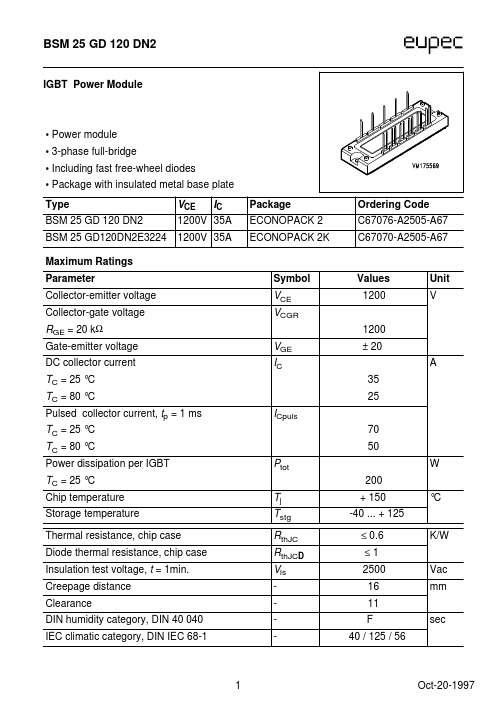
Type BSM 25 GD 120 DN2 BSM 25 GD120DN2E3224
VCE IC 1200V 35A 1200V 35A
Package ECONOPACK 2 ECONOPACK 2K
Maximum Ratings Parameter Collector-emitter voltage Collector-gate voltage RGE = 20 kΩ Gate-emitter voltage DC collector current TC = 25 °C TC = 80 °C Pulsed collector current, tp = 1 ms TC = 25 °C TC = 80 °C Power dissipation per IGBT TC = 25 °C Chip temperature Storage temperature
华氏12012线性4-20mA输出温度传感器说明书

To Order (Specify Model Number)
Model No.
Price Description
Applications
OS1611(*)-(**) OS1711(*)-(**) OS1811(*)-(**)
$ 930 1125 1850
Remote IR sensing head and electronics
Shown smaller than actual size.
OS1700 Series sensor with integral electronics.
ߜ Linear 4 to 20 mA Output
ߜ Simple 2-Wire Installation
ߜ 10 to 40 Vdc Power Operation
ߜ 3 Models to Choose From
ߜ 6 Infrared Spectral Responses
OS1800 Series sensor with integral electronics/display.
OS1600 Series OEM style sensor and remote electronics.
J-95
RUGGED!
INDUSTRIAL!
Rear view showing sensor.
J
OS1811-112-S, $1600, shown actual size.
signal allows the sensor to be interfaced with a variety of remote devices: indicators, controllers, recorders, and/or computers, etc.
高频开关电源模块

高频开关电源模块技术手册石家庄福润新技术有限公司版权所有目录第一章概述 (3)一、简述 (3)二、模块主要特点 (3)三、型号命名 (4)四、技术指标 (4)第二章使用环境 (5)第三章模块构成 (5)一、模块的工作原理 (5)二、模块外观及外形尺寸 (6)三、模块安装 (7)四、操作说明 (11)第一章概述一、简述●我公司自主研发的FRDZ系列智能型高频开关电源,是专为电力系统设计,具有“四遥”功能的高频开关电源,模块采用世界领先的“谐振电压型双环控制的谐振开关电源技术”,具有体积小、重量轻、效率高、可靠性高等优点。
产品包括220V多个型号,配有标准RS-485接口,易于与自动化系统对接,适用于各类变电站、发电厂及水电站。
●我公司第三代(-3型)产品采用了LED数码管显示,进一步提高了产品的可靠性和美观性。
我公司-3型产品主要有以下型号:模块型号额定电压(V)额定电流(A)冷却方式外形尺寸(深×高×宽mm)FRDZ220D05Z-3 220 5 自然冷却260×179×109FRDZ220D07Z-3 220 7 自然冷却325×230×130FRDZ220D10Z-3 220 10 自然冷却325×230×130FRDZ220D20Z-3 220 20 自然冷却400×323×146二、模块主要特点●效率高,模块效率可达到95%~96%。
●重量轻,体积小。
●采用“三相无源功率因数校正电路”,输入无中线,功率因数可达0.94。
●采用隔离自主均流,并机不均流度<±3%,可保证二十台以上模块良好并机。
●模块内置直流输出隔离二极管,用户无需外设。
●模块具有RS-485接口,方便接入自动化系统进行通信。
●模块为LED数码管显示,分别设置显示切换按钮、手动调压按钮、拨码开关,操作简单。
●输出过压保护:内置过压保护电路,出现过压后模块自动锁死,模块故障指示灯亮,故障模块自动退出工作,不影响整个系统正常运行;过压保护点:220V模块为320V±5%,110V模块为160V±5%。
PSPD-25A中文资料
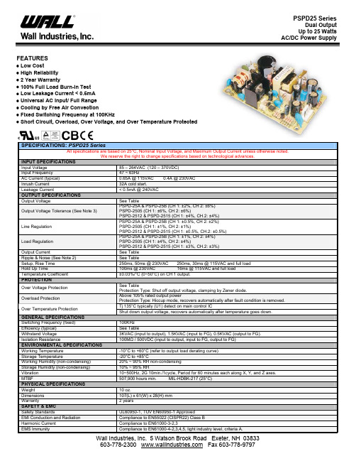
AC/DC Power SupplyFEATURES• Low Cost• High Reliability• 2 Year Warranty• 100% Full Load Burn-In Test• Low Leakage Current < 0.5mA• Universal AC Input/ Full Range• Cooling by Free Air Convection• Fixed Switching Frequency at 100KHz• Short Circuit, Overload, Over Voltage, and Over Temperature ProtectedSPECIFICATIONS: PSPD25 SeriesAll specifications are based on 25o C, Nominal Input Voltage, and Maximum Output Current unless otherwise noted.We reserve the right to change specifications based on technological advances.INPUT SPECIFICATIONSInput Voltage 85 – 264VAC (120 – 370VDC)Input Frequency 47 ~ 63HzAC Current (typical) 0.65A @ 115VAC 0.4A @ 230VACInrush Current 32A cold start.Leakage Current < 0.5mA @ 240VACOUTPUT SPECIFICATIONSOutput Voltage See TableOutput Voltage Tolerance (See Note 3) PSPD-25A & PSPD-25B (CH 1: ±2%, CH 2: ±6%) PSPD-2505 (CH 1: ±6%, CH 2: ±6%)PSPD-2512 & PSPD-2515 (CH 1: ±4%, CH.2: ±4%)Line Regulation PSPD-25A & PSPD-25B (CH 1: ±0.5%, CH 2: ±2%) PSPD-2505 (CH 1: ±1%, CH 2: ±1%)PSPD-2512 & PSPD-2515 (CH 1: ±0.5%, CH.2: ±0.5%)Load Regulation PSPD-25A & PSPD-25B (CH 1: ±1%, CH 2: ±4%) PSPD-2505 (CH 1: ±4%, CH 2: ±4%)PSPD-2512 & PSPD-2515 (CH 1: ±3%, CH.2: ±3%)Output Current See TableRipple & Noise (See Note 2) See TableSetup, Rise Time 250ms, 50ms @ 230VAC 250ms, 30ms @ 115VAC and full load Hold Up Time 100ms @ 230VAC 16ms @ 115VAC and full load Temperature Coefficient ±0.03%/°C (0~50°C) on CH 1 output.PROTECTIONOver Voltage Protection See TableProtection Type: Shut off output voltage, clamping by Zener diode.Overload Protection Above 105% rated output powerProtection Type: Hiccup mode, recovers automatically after fault condition is removed. Tj 135°C typically (U1) detect on main control ICOver Temperature ProtectionShut down output voltage, recovers automatically after temperature goes down. GENERAL SPECIFICATIONSSwitching Frequency (fixed) 100KHzEfficiency (typical) See TableWithstand Voltage 3KVAC (input to output), 1.5KVAC (input to FG), 0.5KVAC (output to FG). Isolation Resistance 100MΩ / 500VDC (input to output, input to FG, output to FG) ENVIRONMENTAL SPECIFICATIONSWorking Temperature -10°C to +60°C (refer to output load derating curve)Storage Temperature -20°C to +85°CWorking Humidity (non-condensing) 20% ~ 90% RH non-condensingStorage Humidity (non-condensing) 10% ~ 95% RHVibration 10~500Hz, 2G 10min./1cycle, Period for 60 minutes each along X, Y, and Z axes. MTBF 507,900 hours min. MIL-HDBK-217 (25°C)PHYSICAL SPECIFICATIONSWeight 10 oz.Dimensions 107(L) x 61(W) x 28(H) mmWarranty 2 yearsSAFETY & EMCSafety Standards UL60950-1, TUV EN60950-1 ApprovedEMI Conduction and Radiation Compliance to EN55022 (CISPR22) Class BHarmonic Current Compliance to EN61000-3-2,3EMS Immunity Compliance to EN61000-4-2,3,4,5, light industry level, criteria A.AC/DC Power SupplyOUTPUT VOLTAGE / CURRENT RATING CHARTModelInput VoltageOutput Voltage Over VoltageProtection Current RangeRated Current Ripple & Noise Output PowerEfficiencyChannel 1 5 VDC 5.75 ~ 6.75V 0.2 ~ 2.5A 2.1A 50mVp-p PSPD-25AChannel 2 12 VDC 13.8 ~ 16.2V 0.1 ~ 1.5A 1.2A 150mVp-p 25W 71%Channel 1 5 VDC 5.75 ~ 6.75V 0.2 ~ 2A 1.2A 50mVp-p PSPD-25B Channel 2 24 VDC 27.6 ~ 32.4V 0.1 ~ 1A 0.8A 200mVp-p 25.2W 77%Channel 1 5 VDC 5.75 ~ 6.75V 0.1 ~ 3A 2.5A 50mVp-p PSPD-2505 Channel 2 -5 VDC -5.75 ~ -6.75V 0.1 ~ 2.5A 2.5A 50mVp-p 25W 73%Channel 1 12VDC 13.8 ~ 16.2V 0.1 ~ 1.2A 1A 50mVp-p PSPD-2512 Channel 2 -12VDC -13.8 ~ -16.2V 0.1 ~ 1.2A 1A 50mVp-p 24W 74%Channel 1 15VDC 17.3 ~ 20.3V 0.1 ~ 1A 0.8A 50mVp-p PSPD-2515 Channel 285~264 VAC(120~370 VDC) -15VDC-17.3 ~ -20.3V0.1 ~ 1A0.8A50mVp-p24W 75%NOTES1. All parameters not specially mentioned are measured at 230VAC input, rated load, and 25°C ambient temperature.2. Ripple & noise are measured at 20MHz using a 12" twisted pair-wire terminated with 0.1uF & 47uF capacitors in parallel .3. Tolerance: includes set up tolerance, line regulation, and load regulation.4. The power supply is considered a component, which will be installed into final equipment. The final equipment must be re-confirmed that it still meets EMC directives.BLOCK DIAGRAMDERATING CURVESTATIC CHARACTERISTICS (A)fosc: 100KHzAC/DC Power Supply MECHANICAL DRAWINGUnit: mmAC INPUT CONNECTOR (CN1)Pin. No Assignment1 AC/L2 NoPin3 AC/NDC OUTPUT CONNECTOR (CN2)Pin No. Assignment1 V1 2,3 COM4 V2。
FGA25N120FTD;中文规格书,Datasheet资料

@ TC = 25oC @ TC = 100oC
Diode continuous Forward current Maximum Power Dissipation Maximum Power Dissipation Operating Junction Temperature
@ TC = 100oC @ TC = 25oC @ TC = 100oC
Symbol
Parameter
Test Conditions
VFM
Diode Forward Voltage
IF = 25A
TC = 25oC TC = 125oC
trr
Diode Reverse Recovery Time
TC = 25oC TC = 125oC
Irr
Diode Reverse Recovery Time
©2009 Fairchild Semiconductor Corporation
1
FGA25N120FTD Rev. A1
G
E
Ratings
1200 ± 25 50 25 75 25 313 125 -55 to +150 -55 to +150 300
Units
V V A A A A W W oC oC
Applications
• Induction heating and Microvewave oven • Soft switching applications
February 2009
tm
General Description
Using advanced field stop trench technology, Fairchild’s 1200V trench IGBTs offer superior conduction and switching performances, and easy parallel operation with exceptional avalanche ruggedness. This device is designed for soft switching applications.
FC系列120瓦特高压电源说明书

FC Series 120 Watt Regulated High Voltage DC Power Supplies1 to 60kV, 1.75” PanelCE CompliantThe FC Series are sophisticated,120 Watt, high voltage power supplies in a small and lightweight package. They are air insulated, fast response units with tight regulation.Fully compliant with the European harmonized EMI directive, EN50082-2, and with the low voltage (safety) directive, 73/23/EEC.Line harmonics are within the European harmonized standard,EN61000-3-2 specifications.FeaturesL ow Stored Energy.Most modelsexhibit less than 1 joule ofstored energy.Pulse-Width Modulation.Off-the-line-pulse-width modulation provides highefficiency and a reduced parts countfor improved reliability.Air Insulated.The FC Series features“air” as the primary dielectricmedium. No oil or encapsulationis used to impede serviceabilityor increase weight.Constant Voltage/Constant CurrentOperation.Automatic crossover fromconstant-voltage to constant-currentregulation provides protection againstoverloads, arcs, and short circuits.Low Ripple.Ripple is less than 0.02%of rated voltage at full load.Tight Regulation.Voltage regulationis better than 0.005% for allowableline and load variations. Currentregulation is better than 0.05%from short circuit to rated voltage.Front Panel Controls.Separate10-turn controls with locking vernierdials are used to set voltage andcurrent levels. A high voltage enable(on) switch and an AC power on/offswitch complete the panel controls.L.E.D.’s indicate when high voltage ison, the output polarity, and whetherthe supply is operating in a voltage orcurrent regulating mode. For the blankpanel version, only a power on/offswitch is provided on the panel.Remote Control Facilities. Asstandard, all FC Series suppliesprovide output voltage and currentprogram/monitor signals, highvoltage enable, safety interlockterminals, and a +10 voltreference source.Small Size and Weight.FC Seriespower supplies occupy only 1.75inches of panel height. Net weightis less than 12 pounds.Warranty. Standard power suppliesare warranted for three years; OEMand modified power supplies arewarranted for one year. A formalwarranty statement is available.Models from 0 to 1kV through 0 to 60kV, 1.75” H x 19” W x 20.25” D, 12 lbs.C he ckt hes pe cs…a ndc omp ar eDesigning Solutions for High Voltage Power Supply ApplicationsGLASSMAN HIGH VOLTAGE INC.124 West Main Street,PO Box 317,High Bridge,NJ 08829-0317(908) 638-3800 • Fax (908) 638-3700 • GLASSMAN EUROPE Limited (UK)GLASSMAN JAPAN High Voltage Limited +44 1256 883007 FAX +44 1256 883017 +81 45 902 9988 FAX+81 45 902 2268 E-mail:******************************E-mail:*****************************©Glassman High Voltage, Inc.Printed in the U.S.A. B 12/18/2003program/monitor, HV enable, ground,and local control. A rear panel toggle switch selects either local or remote operation.External Interlock: Open off, closed on. Normally latching except for blank panel version where it is non-latching.Specifications(Specifications apply from 5 to 100%rated voltage. Operation is guaranteed down to 0% of rated voltage with aslight degradation of ripple, regulation, and stability.)Input: 102-132V RMS, single-phase, 48-420 Hz, <2.5A. Connectorper IEC 320 with mating line cord terminated with NEMA 5-15 plug.Efficiency:Typically 80% at full load.Output:Continuous, stable adjust-ment,from 0 to rated voltage or current by panel mounted 10-turn potentiometers with 0.05% resolution, or by external 0to 10V signals is provided. Voltage accuracy is 0.5% of setting +0.2% of rated. Repeatability is <0.1% of rated.Stored Energy:See Models chart.Static Voltage Regulation:Better than 0.005% for specified line variations and 0.005% + 0.5 mV/mA for load variations.Dynamic Voltage Regulation:For load transients from 10% to 100% and 100%to 10%, typical deviation is 2% of output voltage with recovery to within 1% in 500 µs and to 0.1% in 1 ms.Ripple:<0.02% of rated voltage plus 300mV RMS at full load.Current Regulation: Better than 0.1%from short circuit to rated voltage at any load condition.Voltage Monitor:0 to +10 V equivalent to 0 to rated voltage. Accuracy, 0.5% of reading +0.2% rated.Current Monitor:0 to +10 V equivalent to 0 to rated current. Accuracy, 1% of reading +0.05% rated. Reversible polar-ity models: 1% of reading + 0.1% of rated.Stability: 0.01% per hour after 1/2 hour warmup, 0.05% per 8 hours.Voltage Rise/Decay Time Constant:400 ms typical with a 10% resistive load using either HV on/off or remote programming control.Temperature Coefficient:0.01% per degree C.Ambient Temperature:-20 to +50 degrees C, operating; -40 to +85 degrees C, storage.Polarity:Available with either positive, negative, or reversible polarity with respect to chassis ground.Protection:Automatic current regulation protects against all overloads, including arcs and shorts. Fuses, surge-limiting resistors, and low energy components provide ultimate protection.Remote Controls: A five position terminal block and a 15 Pin “D”connector are provided for all remote functions, including common, +10 V reference, interlock, voltage and currentDesigning Solutions for High Voltage Power Supply ApplicationsGLASSMAN HIGH VOLTAGE INC .124 West Main Street,PO Box 317,High Bridge,NJ 08829-0317(908) 638-3800 • Fax (908) 638-3700 • OptionsSymbol Description10090 to 110VRMS input, 48-420Hz. NEMA 5-15 Plug. 220198 to 250VRMS input, 48-420Hz. NEMA 6-15 Plug. NC Blank front panel, power switch only.CTCurrent trip. Power supply trips off when the load current reaches the programmed level. This option has a rear panel switch that selects either “trip” operation or current limiting.ZR Zero start interlock. Voltage control, local or remote, must be atzero before HV will enable.SS Slow start ramp. Specify standard times of 1, 2, 3, 5, 10, 15, 20,or 30 s +/- 20%.X130-5 V voltage and current program/monitor.HVS High voltage status indicator. Normally open relay contactsthat close when HV is enabled. Contacts are rated for 24VDC at 1A maximum.Please consult factory for special requirements.Remote HV Enable:0-1.5 V off, 2.5-15 V on.Accessories:Detachable 8 foot shielded high voltage coaxial cable (see Models chart for cable type), 6 foot detachable line cord, and mating 15 Pin “D” connec-tor and shell are provided.ModelsPositive Negative Reversible Output Output Stored Output PolarityPolarityPolarityVoltageCurrentEnergyCableFC1P120FC1N120FC1R1200 - 1kV 0 - 120mA 0.2 J RG - 58FC1.5P80FC1.5N80FC1.5R800 - 1.5kV 0 - 80mA 0.45 J RG - 58FC2P60FC2N60FC2R600 - 2kV 0 - 60mA 0.1 J RG - 58FC3P40FC3N40FC3R400 - 3kV 0 - 40mA 0.2 J RG - 58FC5P24FC5N24FC5R240 - 5kV 0 - 24mA 0.3 J RG - 58FC6P20FC6N20FC6R200 - 6kV 0 - 20mA 0.25 J RG - 8U FC8P15FC8N15FC8R150 - 8kV 0 - 15mA 0.3 J RG - 8U FC10P12FC10N12FC10R120 - 10kV 0 - 12mA 0.4 J RG - 8U FC12P10FC12N10FC12R100 - 12kV 0 - 10mA 0.7 J RG - 8U FC15P8FC15N8FC15R80 - 15kV 0 - 8mA 1.1 J RG - 8U FC20P6FC20N6FC20R60 - 20kV 0 - 6mA 0.85 J RG - 8U FC25P4.8FC25N4.8FC25R4.80 - 25kV 0 - 4.8mA 1 J RG - 8U FC30P4FC30N4FC30R40 - 30kV 0 - 4mA 1 J RG - 8U FC40P3FC40N3FC40R30 - 40kV 0 - 3mA 1.5 J RG - 8U FC50P2.4FC50N2.4FC50R2.40 - 50kV 0 - 2.4mA 2 J RG - 8U FC60P2FC60N2FC60R20 - 60kV0 - 2mA2.4 JRG - 8U。
IXFN120N20中文资料
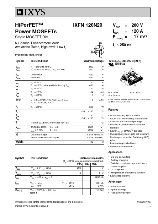
Symbol Test ConditionsMaximum RatingsV DSS T J = 25°C to 150°C200V V DGR T J = 25°C to 150°C; R GS = 1 M W 200V V GS Continuous ±20V V GSM Transient±30V I D25T C = 25°C120A I DM T C = 25°C, pulse width limited by T JM 480A I AR T C = 25°C 120A E AR T C = 25°C 64mJ E AS T C = 25°C3J dv/dt I S £ I DM , di/dt £ 100 A/m s, V DD £ V DSS 5V/ns T J £ 150°C, R G = 2 W P D T C = 25°C600W T J -55 ... +150°C T JM 150°C T stg -55 ... +150°C T L 1.6 mm (0.063 in.) from case for 10 s -°C V ISOL 50/60 Hz, RMS t = 1 min 2500V~I ISOL £ 1 mAt = 1 s3000V~M d Mounting torque1.5/13 Nm/lb.in.Terminal connection torque 1.5/13Nm/lb.in.Weight30gSymbol Test ConditionsCharacteristic Values(T J = 25°C, unless otherwise specified)min.typ.max.V DSS V GS = 0 V, I D = 3mA 200V V GS(th) V DS = V GS , I D = 8mA 24 V I GSS V GS = ±20 V, V DS = 0±200 nAI DSS V DS = V DSS T J = 25°C 100 m A V GS = 0 VT J = 125°C2 mA R DS(on)V GS = 10 V, I D = 0.5 • I D2517 m WNote 196538C (7/99)IXFN 120N20V DSS = 200V I D25= 120A R DS(on)=17 m Wt rr £ 250 nsHiPerFET TMPower MOSFETsSingle MOSFET DieN-Channel Enhancement ModeAvalanche Rated, High dv/dt, Low t rrSGSDminiBLOC, SOT-227 B (IXFN) E153432G = Gate D = DrainS = SourceEither Source terminal at miniBLOC can be used as Main or Kelvin SourceFeatures•Encapsulating epoxy meetsUL 94 V-0, flammability classification •International standard package •miniBLOC, with Aluminium nitride isolation•Low R DS (on) HDMOS TM process•Rugged polysilicon gate cell structure •Unclamped Inductive Switching (UIS)rated•Low package inductance •Fast intrinsic Rectifier Applications•DC-DC converters •Battery chargers•Switched-mode and resonant-modepower supplies •DC choppers•Temperature and lighting controls •Low voltage relays Advantages•Easy to mount •Space savings •High power densityPreliminary data sheetIXYS reserves the right to change limits, test conditions, and dimensions.Symbol Test Conditions Characteristic Values Array= 25°C, unless otherwise specified)(T ArrayNote: 1. Pulse test, t £ 300 m s, duty cycle d £ 2 %。
PM25RLA120中文资料
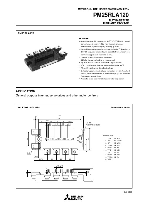
PM25RLA120FEATUREa)Adopting new 5th generation IGBT (CSTBT) chip, which performance is improved by 1µm fine rule process.For example, typical V ce (sat)=1.9V @Tj=125°Cb)I adopt the over-temperature conservation by Tj detection of CSTBT chip, and error output is possible from all each con-servation upper and lower arm of IPM.c)Current rating of brake part increased.60% for the current rating of inverter part.•3φ 25A, 1200V Current-sense IGBT type inverter •15A, 1200V Current-sense regenerative brake IGBT •Monolithic gate drive & protection logic•Detection, protection & status indication circuits for, short-circuit, over-temperature & under-voltage (P-Fo available from upper arm devices)•Acoustic noise-less 3.7kW class inverter applicationAPPLICATIONGeneral purpose inverter, servo drives and other motor controls PACKAGE OUTLINES Dimensions in mm1. VUPC2. UFO3. UP4. VUP15. VVPC6. VFO7. VP8. VVP19. VWPC 10. WFO11. WP 12. VWP113. VNC 14. VN115. Br 16. UN 17. VN 18. WN 19. FoTerminal code 10619.753.2571615.252-φ5.56-φ6MOUNTING HOLES6-23-23-23-2BNPUVW10.75619- 0.532.75232323136315532351616120INSULATED PACKAGEINSULATED PACKAGEParameterSymbolSupply Voltage Protected bySCSupply Voltage (Surge)Module Case OperatingTemperatureStorage Temperature Isolation Voltage ConditionV CC(surge)T CT stgV iso Ratings V CC(PROT)8001000–20 ~ +100–40 ~ +1252500Unit V °C °C V rmsV V D = 13.5 ~ 16.5V, Inverter Part,T j = +125°C StartApplied between : P-N, Surge value (Note-2)60Hz, Sinusoidal, Charged part to Base, AC 1 min.TOTAL SYSTEMUPIGBT 29.0–7.1VPWPUNVNWNBr FWDi 29.31.5IGBT 65.0–7.1FWDi 65.52.0IGBT 85.6–7.1FWDi 85.92.0IGBT 37.85.1FWDi 37.5–4.5IGBT 55.25.1FWDi 55.7–4.5IGBT 75.85.1FWDi 75.3–4.5IGBT19.0–7.3FWDi 22.36.6armaxisX Y(Unit : mm)Bottom view Top viewB N PU V WT C (Base plate)Table1 : T C measurement point of just under the chips.2.32.43.52.50.81.03.01.2110Min.Typ.Max.Collector-Emitter Saturation Voltage Collector-Emitter Cutoff Current–I C = 25A, V D = 15V, V CIN = 15V (Fig. 2)T j = 25°C T j = 125°CELECTRICAL CHARACTERISTICS (Tj = 25°C, unless otherwise noted)INVERTER PARTParameterSymbol ConditionV CE(sat)I CESV EC t on t rr t c(on)t off t c(off)Limits ———0.5——————1.81.92.51.00.50.42.00.7——T j = 25°C T j = 125°CFWDi Forward VoltageSwitching TimeV D = 15V, V CIN = 0V ↔15V V CC = 600V, I C = 25A T j = 125°C Inductive Load (Fig. 3,4)V CE = V CES , V CIN = 15V(Fig. 5)V D = 15V, I C = 25AV CIN = 0V, Pulsed(Fig. 1)V mAVµsUnit 0.831.360.961.821.081.771.252.370.038°C/WR th(j-c)Q R th(j-c)F R th(j-c)Q R th(j-c)F R th(j-c)Q R th(j-c)F R th(j-c)Q R th(j-c)F R th(c-f)Inverter IGBT (per 1 element) (Note-1)Inverter FWDi (per 1 element) (Note-1)Brake IGBT (Note-1)Brake FWDi(Note-1)Inverter IGBT (per 1 element) (Note-2)Inverter FWDi (per 1 element) (Note-2)Brake IGBT (Note-2)Brake FWDi(Note-2)Case to fin, (per 1 module)Thermal grease appliedSymbol ConditionUnitMin.——————————————————Junction to case Thermal ResistancesTHERMAL RESISTANCESContact Thermal ResistanceParameterLimits Typ.Max.(Note-1)T C measurement point is just under the chips (Bottom view).If you use this value, R th(f-a) should be measured just under the chips.(Note-2)T C measurement point is as shown below (Top view).INSULATED PACKAGE—————V CE(sat)I CESV FM V mAMin.Typ.Max.V Collector-Emitter Saturation Voltage FWDi Forward Voltage Collector-Emitter Cutoff CurrentI F = 15A(Fig. 2)T j = 25°C T j = 125°CUnit ParameterSymbol ConditionLimits 2.32.43.51101.81.92.5——T j = 25°C T j = 125°CBRAKE PARTV D = 15V, I C = 15A V CIN = 0V, Pulsed (Fig. 1)V CE = V CES , V CIN = 15V(Fig. 5)V D = 15V, V CIN = 15VApplied between :U P -V UPC , V P -V VPC , W P -V WPCU N • V N • W N • B r -V NCI D °C V mA ms30101.82.3———155—12.5—0.0115—mA Circuit CurrentInput ON Threshold Voltage Input OFF Threshold Voltage Short Circuit Trip Level Short Circuit Current Delay TimeOver Temperature Protection Supply Circuit Under-Voltage ProtectionFault Output Current Minimum Fault Output Pulse WidthV th(ON)V th(OFF)SC t off(SC)OT OT r UV UV r I FO(H)I FO(L)t FOTrip level Reset level Trip level Reset levelCONTROL PART——1.21.75030—135—11.5———1.0ParameterSymbol ConditionUnit 2051.52.0——0.214512512.012.5—101.8(Note-3)Fault output is given only when the internal SC, OT & UV protections schemes of either upper or lower arm device operate toprotect it.Detect T j of IGBT chip –20 ≤ T j ≤ 125°C V D = 15V, V CIN = 15V (Note-3)V D = 15V(Note-3)V µs V N1-V NC V XP1-V XPCInverter partBrake part A –20 ≤ T j ≤ 125°C, V D = 15V (Fig. 3,6)V D = 15V(Fig. 3,6) 3.53.5————Mounting part screw : M5Mounting partscrew : M5—Symbol Mounting torque Mounting torque WeightN • m N • m g2.52.5—3.03.0380MECHANICAL RATINGS AND CHARACTERISTICSParameterConditionUnit Max.Min.Typ.Limits Max.Min.Typ.Limits RECOMMENDED CONDITIONS FOR USERecommended valueUnit ConditionSymbol ParameterV Applied across P-N terminalsApplied between :V UP1-V UPC , V VP1-V VPCV WP1-V WPC , V N1-V NC (Note-4)Applied between :U P -V UPC , V P -V VPC , W P -V WPCU N • V N • W N • B r -V NCUsing Application Circuit of Fig. 8For IPM ’s each input signals(Fig. 7)Supply Voltage Control Supply Voltage Input ON Voltage Input OFF Voltage PWM Input Frequency Arm Shoot-through Blocking Time≤ 80015.0±1.5≤ 0.8≥ 9.0≤ 20≥ 2.5V CC V CIN(ON)V CIN(OFF)f PWM t deadV D V V kHz µs(Note-4)With ripple satisfying the following conditions dv/dt swing ≤ ±5V/µs, Variation ≤ 2V peak to peakINSULATED PACKAGEINSULATED PACKAGE。
kw25n120中文资料

Preliminary
SKW25N120
Fast S-IGBT in NPT-technology with soft, fast recovery anti-parallel EmCon diode
C
• 40% lower Eoff compared to previous generation • Short circuit withstand time – 10 µs
td(on) tr td(off) tf Eon Eoff Ets
Anti-Parallel Diode Characteristic Diode reverse recovery time
Diode reverse recovery charge Diode peak reverse recovery current Diode peak rate of fall of reverse recovery current during tF
trr tS tF Qrr Irrm dirr/dt
Tj=25°C, VCC=800V,IC=25A, VGE=15/0V, RG=22Ω, Energy losses include “tail” and diode reverse recovery.
Tj=25°C, VR=800V, IF=25A, diF/dt=650A/µs
- parallel switching capability
Type SKW25N120
VCE
IC
1200V 25A
Eoff 2.9mJ
Tj
Package
150°C TO-247AC
Maximum Ratings
Parameter
IRFR120NTR中文资料
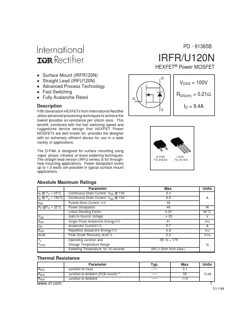
IRFR/U120NHEXFET ®Power MOSFETDescription5/11/98ParameterMax.UnitsI D @ T C = 25°C Continuous Drain Current, V GS @ 10V 9.4I D @ T C = 100°C Continuous Drain Current, V GS @ 10V 6.6A I DMPulsed Drain Current 38P D @T C = 25°C Power Dissipation 48W Linear Derating Factor 0.32W/°C V GS Gate-to-Source Voltage± 20V E AS Single Pulse Avalanche Energy 91mJ I AR Avalanche Current5.7A E AR Repetitive Avalanche Energy 4.8mJ dv/dt Peak Diode Recovery dv/dt 5.0V/ns T J Operating Junction and-55 to + 175T STGStorage Temperature RangeSoldering Temperature, for 10 seconds300 (1.6mm from case )°CAbsolute Maximum RatingsParameterTyp.Max.UnitsR θJC Junction-to-Case––– 3.1R θJA Junction-to-Ambient (PCB mount) **–––50°C/WR θJAJunction-to-Ambient–––110Thermal ResistanceD -P AK T O -252AA I-PA K TO -251AAl Surface Mount (IRFR120N)l Straight Lead (IRFU120N)l Advanced Process Technology l Fast SwitchinglFully Avalanche RatedFifth Generation HEXFETs from International Rectifier utilize advanced processing techniques to achieve the lowest possible on-resistance per silicon area. This benefit, combined with the fast switching speed and ruggedized device design that HEXFET Power MOSFETs are well known for, provides the designer with an extremely efficient device for use in a wide variety of applications.The D-PAK is designed for surface mounting using vapor phase, infrared, or wave soldering techniques.The straight lead version (IRFU series) is for through-hole mounting applications. Power dissipation levels up to 1.5 watts are possible in typical surface mount applications.PD - 91365BIRFR/U120NIRFR/U120NIRFR/U120NIRFR/U120NIRFR/U120NIRFR/U120NIRFR/U120NIRFR/U120NIRFR/U120N元器件交易网Note: For the most current drawings please refer to the IR website at:/package/。
同位素
同位素科技名词定义中文名称:同位素英文名称:isotope定义1:具有相同原子序数(即质子数相同,因而在元素周期表中的位置相同),但质量数不同,亦即中子数不同的一组核素。
所属学科:电力(一级学科) ;核电(二级学科)定义2:中子数不同的同一种元素的一种原子形式,包括稳定同位素和放射性同位素。
所属学科:生态学(一级学科) ;全球生态学(二级学科)本内容由全国科学技术名词审定委员会审定公布百科名片氕与氘互为同位素具有相同质子数,不同中子数(或不同质量数)同一元素的不同核素互为同位素(Isotopes)。
目录[隐藏]定义概述同位素列表同位素和其他核技术的开发应用[编辑本段]定义以上定义中的原子是广义的概念,指微观粒子。
例如氢有三种同位素,H氕、D氘(又叫重氢)、T氚(又叫超重氢);碳有多种同位素,例如12C(12为上标,下同)、14C等。
在19世纪末先发现了放射性同位素,随后又发现了天然存在的稳定同位素,并测定了同位素的丰度。
大多数天然元素都存在几种稳定的同位素。
同种元素的各种同位素质量不同,但化学性质几乎相同。
许多同位素有重要的用途,例如12C是作为确定原子量标准的原子;两种H 原子是制造氢弹的材料;235U是制造原子弹的材料和核反应堆的原料。
同位素示踪法广泛应用于科学研究、工农业生产和医疗技术方面,例如用O标记化合物确证了酯化反应的历程,I 用于甲状腺吸碘机能的实验等。
[编辑本段]概述同位素是具有相同原子序数的同一化学元素的两种或多种原子之一,在元素周期表上占有同一位置,化学行为几乎相同,但原子质量或质量数不同,从而其质谱行为、放射性转变和物理性质(例如在气态下的扩散本领)有所差异。
同位素的表示是在该元素符号的左上角注明质量数,例如碳14,一般用C14而不用14C.自然界中许多元素都有同位素。
同位素有的是天然存在的,有的是人工制造的,有的有放射性,有的没有放射性。
同一元素的同位素虽然质量数不同,但他们的化学性质基本相同(如:化学反应和离子的形成),物理性质有差异[主要表现在质量上(如:熔点和沸点)]。
IRFR120资料

-
2.2 3.3 nC
Qgd
-
2.3 3.4 nC
CISS VDS = 25V, VGS = 0V, f = 1MHz (Figure 11)
-
350
-
pF
COSS
-
130
-
pF
CRSS
-
24
-
pF
LD
Measured from the Drain Modified MOSFET
-
4.5
-
nH
Lead, 6.0mm (0.25in) from Symbol Showing the
-
-
25
µA
-
250 µA
ID(ON) VDS > ID(ON) x rDS(ON)MAX, VGS = 10V
8.4
-
-
A
IGSS VGS = ±20V
-
- ±500 nA
rDS(ON) ID = 5.9A, VGS = 10V (Figures 8, 9)
- 0.25 0.27 Ω
gfs
VDS ≥ 50V, ID = 5.9A (Figure 12)
Packaging
JEDEC TO-251AA
SOURCE DRAIN GATE
DRAIN (FLANGE)
Features
• 8.4A, 100V • rDS(ON) = 0.270Ω • Single Pulse Avalanche Energy Rated • SOA is Power Dissipation Limited • Nanosecond Switching Speeds • Linear Transfer Characteristics • High Input Impedance • Related Literature
ntc_热敏电阻_20d-25pdf参数_理论说明

ntc 热敏电阻20d-25pdf参数理论说明1. 引言1.1 概述在现代电子技术领域,NTC(Negative Temperature Coefficient)热敏电阻被广泛应用于温度测量和控制系统中。
NTC热敏电阻具有随温度变化而变化的电阻特性,即温度越高,其电阻值越小;反之,温度越低,其电阻值越大。
这种特性使得NTC热敏电阻成为一种重要的元件,在温度测量和控制领域发挥着重要的作用。
1.2 文章结构本文将对NTC热敏电阻型号为20d-25pdf的参数进行理论说明和分析。
文章结构如下:第2部分将介绍NTC热敏电阻的工作原理和基本概念;第3部分将详细解释20d-25pdf参数,并对其进行理论说明;第4部分将总结本文要点,并展望20d-25pdf参数在未来的应用前景;最后,我们列出参考文献供读者进一步深入学习和了解。
1.3 目的本文旨在深入理解NTC热敏电阻,并通过对20d-25pdf参数进行理论说明,帮助读者更好地理解和应用该型号的热敏电阻。
通过本文的阐述,读者将能够从理论层面对NTC热敏电阻进行分析,并掌握20d-25pdf参数在不同温度条件下的变化规律。
此外,文章还将展望20d-25pdf参数在未来温度测量和控制系统中的潜在应用前景,为相关领域的工程师和研究人员提供参考和指导。
2. 正文在本文的正文部分,将详细介绍ntc热敏电阻20d-25pdf参数的理论说明。
我们将从以下几个方面进行讨论:材料特性、工作原理以及性能参数等。
2.1 材料特性NTC热敏电阻(Negative Temperature Coefficient Thermistor)是一种温度敏感元件,其电阻值随着温度变化而发生变化。
它通常由氧化物陶瓷材料制成,主要成分包括镍、锌、铁、锰等金属氧化物。
该材料具有高精度、快速响应和稳定可靠的特点,在温度检测和控制领域得到广泛应用。
2.2 工作原理NTC热敏电阻基于半导体材料的负温度系数效应工作。
DFB2540;中文规格书,Datasheet资料

September 2012
DFB2505 - DFB25100 Glass Passivated Bridge Rectifiers
Features
• • • • • • • • UL Certificate # E326243 Glass Passivated Junction Ideal for Printed Circuit Board Reliable Low Cost Construction Plastic Material has Underwriters Laboratory Flammability Classification 94V-0 Surge Overload Rating to 350 Amperes Peak High Case Dielectric Strength of 2500 VRMS Isolated Voltage from Case to Lead Over 2500 Volts
Electrical Characteristics
Symbol
VF IR I2t Cj
TA = 25°C unless otherwise specified
Parameter
Maximum Instantaneous Forward Voltage Maximum DC Reverse Current at Rated DC Blocking Voltage Rating for fusing (t < 8.3mS) Typical Junction Capacitance per leg*
+ ~ ~
华氏12012系列Pt100 RTD 和热敏电阻探头产品说明书

Pt100 RTD &Thermocouple Probes for Industrial Applications AVAILABLE VERSIONS:ߜPt100 in class A, 1/3 DIN and 1/10 DIN availableߜThermocouples J, K, T, E & L with accuracy to IEC class 1ߜTemperature range -100°C to +400°CߜStandard closed end sensors or airstream models availableߜStandard lengths up to 200mm, optional lengths 0f 201-500mmߜDiameter 3mm or 6mmߜA range of mounting threads ߜAll Pt100 sensors have a 4-wire connectionߜA broad range of lead wire materials availableOMEGA temperature probes for industrial applications are produced with a wide variety of mechanical attachment systems suitable for a range of process conditions.They may be specified to your precise requirements by the sensor type in either a closed-end or airstream version, accuracy, probe length, different threads, wire material in shielded and unshieldedversions.SpecificationsTemperature range:-100°C to +400°CLead wire temperature range: PVC 100°C (max), Silicone rubber 200°C (max), FEP 250°C (max), Fibreglass 400°C (max)Sheath material:Stainless steel grade 304 Maximum pressure:Ø6mm - 40bar, Ø3mm - 20bar Response time T66 in liquid:Pt100 closed end probe: 3 secondsThermocouple: 4 secondsResponse time T66 in air:Pt100 closed end probe 15 secondsThermocouples: 5 secondsSensor Configuration:Pt100: 4-wire systemThermocouples: UngroundedThe standard temperature range is -100°C to +400°C. Selection of thewire insulation, i.e. PVC, Silicone,FEP or Glass will effect themaximum probe temperature. Do notexceed the maximum temperature ofthe insulation at the transitionbetween the probe and wire.* Thermocouples are supplied with Class 1 accuracy as standard. ** The probe diameters shown above are available with the thread sizes indicated. *** The lead wire is supplied in multiples of one metre.Ordering example 1: K-L-1-3-50-PS-1Thermocouple type K airstream probe with Class 1 accuracy and diameter of 3mm. The probe length is 50mm with 1 metre of PVC shielded lead wire.Ordering example 2: P-M-1/3-6-100-M10-S-8Pt100 closed end probe with 1/3 DIN accuracy and diameter of 6mm. The probe length is 100mm with an M10 x 1 mounting bush and 8 metres of silicone lead wire.。
德欣集团热保护压敏电阻产品规格说明书

SPD Series Specifications德欣集团深圳市德欣电器有限公司SPD全系列规格书产品名称:热保护压敏电阻型号规格: COV25D-COV60D(201K~162K)日期: 2019年6月30日本集团公司旗下总生产面积 60000 平米以上,主营产品压敏芯片及压敏电阻器,电压范围从15V--1800V,产品直径从3mm--80mm均能全系列生产,年产能压敏芯片12亿只以上,压敏电阻器成品8亿只以上,综合年产能20亿只以上,为国内压敏芯片,压敏电阻器产能最大生产商之一,其中(15V-82V)低压压敏芯片,产能,产量,市场占有率位居世界第一。
本公司旗下所生产的全系列产品均有完善的认证体系:具备CQC,UL,CSA,VDE,SGS等多国认证,产品畅销多个国家,全员推行并遵守ISO9001质量管理体系,ISO14001环境管理体系,OHSAS18001职业健康安全管理体系,拥有国家发明专利6项,实用新型专利7项,为高新技术企业。
华北生产基地:山东省德州市平原县经济开发区德欣电器高新科技产业园华南生产基地:惠州市惠阳区秋长将军路合美兴工业园西南生产基地:四川省南充市阆中市七里汉王祠路小微企业孵化园 3 号联系人:林茂发移动电话:136****5669固定电话:*************官方网站:SPD Series Specifications SPD 系列规格说明 Explanation of Part Numbers 型号说明:-Specifications 规格说明:□Varistor Voltage Range压敏电阻动作电压范围 200V~1600V(dc) □Peak Current For 8/20us Current Wave在8/20us电流波形最大通流量 20KA~70KA □Energy Range For 10/1000us Current Wave在10/1000us电流波形的能量范围 250J~2500J □Storage Temperature Range储存温度范围 -40℃~85℃℃ □Operation Ambient Temperature Range作业环境温度范围储存温度范围 -40℃~85℃ □Typical Response Time反应时间 〈25ns □Insulation Resistance绝缘电阻 ≧1000MΩApplications 应用领导域:▇ Protection Of Communication Against Lightning 通信电源防雷保护▇ Industrial Power Distributors 工业配电柜▇ Railway Highway and Air-signal 铁路、公路、航空信号系统▇ Building Power Distributors Input Against Lightning 大楼供电电源入端防雷COV D KC Common Code 产品类别代码DE xin COV Metal Oxide Varistor Surg e Absorber 德欣COV 金属氧化物压敏电阻器 25 32,.34 53 60ChipDiameter 芯片直径 Φ25mm Φ32mm S34mm Φ53mm Φ60mmChip .Shape芯片形状Varistor Voltage 压敏电阻动作电压例如Examples: 47 × 100 = 47 V 47 × 101 = 470 V 11 × 102 = 1100 V47471112Tolerance 误差 K .±10%L .±15% M .±20% OrCustomer Special Requirem entD-Disc 圆形B-Block 塑胶方S-Square 方形Enclosure 包封材质C:Epoxy 环氧树脂 E:Plastic...Case 注塑外壳Tab Style 引出端形状P Planet 平板型 L L Shape L 型 C Radial 圆型L•25D Specifiation*32D Specification(表一:基本尺寸表)(表二:厚度尺寸表) (图1:32D系列简图)SPD Series Specifications *40D Specification(表一:基本尺寸表)(表二:厚度尺寸表) (图1:40D系列简图)*53D Specification(表一:基本尺寸表)(表二:厚度尺寸表) (图1:53D系列简图)*34S Specification(表一:基本尺寸表)(表二:厚度尺寸表) (图1:34S系列简图)*34B (BLOCK VARISTOR) Specification注:未注明公差±0.5mm(图1:34B系列简图)*60B (BLOCK VARISTOR) Specification注:未注明公差±0.5mm(图1:60B系列简图)V-I Curve 电压电流特性曲线:第 21 页 SPD Series Specifications。
阿里安洗衣机安装 操作 维护手册说明书

©2019 年 Alliance Laundry Systems LLC,版权所有 保留所有权利。未经出版商明确书面授权,不得以任何形式或方式复制或传输本手册的任何部分或内容。
适合滚筒烘干机使用的具体类型。详情参考关于排气系统连接的部分。柔性排气材料会皱缩,易被压碎,堆积棉绒。 这些特点会阻碍滚筒烘干机中的空气流通,增加发生火灾的风险。
W752R1
以下信息适用于美国马萨诸塞州。 • 该电器只能由马萨诸塞州的持证水暖工或煤气设备安装工进行安装。 • 本设备必须使用 91 厘米 [36 英寸]长的气体用软接头进行安装。 • T 型手柄的燃气截止阀必须安装在本设备的供气管道上。 • 本设备不得安装在卧室或浴室中。
安全信息...............................................................................................12 安全提示说明.............................................................................................. 12 重要安全说明.............................................................................................. 12
警告
为了您的安全,请务必遵守本手册中规定的信息以最大程度减少发生火灾、爆炸的发生或避免财产损失、人身伤害或死 亡。
W033
警告
• 请勿将在本设备或任何其他设备附近存放或使用汽油或其他易燃气体和液体。 • 闻到燃气味时的处理方法:
• 请勿尝试开启任何设备。 • 请勿触摸任何电器开关;请勿在您所在的建筑物内使用电话。 • 疏散所有人员离开房间、建筑物或所在区域。 • 立即使用邻居的电话联系您的燃气供应商。遵循燃气供应商的操作指示。 • 如果您无法联系燃气供应商,请呼叫消防队。 • 本设备必须由合格的安装人员、服务机构或燃气供应商进行安装及维修。
常用场效应管(25N120等)参数及代换
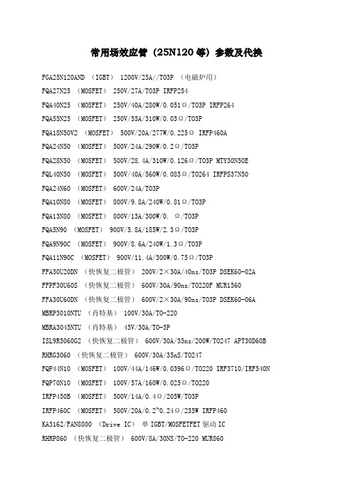
常用场效应管(25N120等)参数及代换FGA25N120AND (IGBT) 1200V/25A//TO3P (电磁炉用)FQA27N25 (MOSFET) 250V/27A/TO3P IRFP254FQA40N25 (MOSFET) 250V/40A/280W/0.051Ω/TO3P IRFP264FQA55N25 (MOSFET) 250V/55A/310W/0.03Ω/TO3PFQA18N50V2 (MOSFET) 500V/20A/277W/0.225Ω IRFP460AFQA24N50 (MOSFET) 500V/24A/290W/0.2Ω/TO3PFQA28N50 (MOSFET) 500V/28.4A/310W/0.126Ω/TO3P MTY30N50EFQL40N50 (MOSFET) 500V/40A/560W/0.085Ω/TO264 IRFPS37N50FQA24N60 (MOSFET) 600V/24A/TO3PFQA10N80 (MOSFET) 800V/9.8A/240W/0.81Ω/TO3PFQA13N80 (MOSFET) 800V/13A/300W/0. Ω/TO3PFQA5N90 (MOSFET) 900V/5.8A/185W/2.3Ω/TO3PFQA9N90C (MOSFET) 900V/8.6A/240W/1.3Ω/TO3PFQA11N90C (MOSFET) 900V/11.4A/300W/0.75Ω/TO3PFFA30U20DN (快恢复二极管) 200V/2×30A/40ns/TO3P DSEK60-02A FFPF30U60S (快恢复二极管) 600V/30A/90ns/TO220F MUR1560FFA30U60DN (快恢复二极管) 600V/2×30A/90ns/TO3P DSEK60-06A MBRP3010NTU (肖特基) 100V/30A/TO-220MBRA3045NTU (肖特基) 45V/30A/TO-3PISL9R3060G2 (快恢复二极管) 600V/30A/35ns/200W/TO247 APT30D60B RHRG3060 (快恢复二极管) 600V/30A/35nS/TO247FQP44N10 (MOSFET) 100V/44A/146W/0.0396Ω/TO220 IRF3710/IRF540N FQP70N10 (MOSFET) 100V/57A/160W/0.025Ω/TO220IRFP450B (MOSFET) 500V/14A/0.4Ω/205W/TO3PIRFP460C (MOSFET) 500V/20A/0.2~0.24Ω/235W IRFP460KA3162/FAN8800 (Drive IC)单IGBT/MOSFETFET驱动ICRHRP860 (快恢复二极管) 600V/8A/30NS/TO-220 MUR860RHRP1560 (快恢复二极管) 600V/15A/TO0220 MUR1560RHRP8120 (快恢复二极管) 1200V/8A/75W/TO220RHRP15120 (快恢复二极管) 1200V/15A/TO220RHRP30120 (快恢复二极管) 1200V/30A/125W/TO220单 DSEI20-10ARHRG30120 (快恢复二极管) 1200V/30A/T03PSSH45N20B (MOSFET) 200V/45A/TO3P IRFP260FGL40N150D (IGBT) 1500V/40A/TO264快速IGBTFGL60N100BNTD (IGBT) 1000V/60A/TO264快速IGBT 1MBH60-100HGTG10N120BND (IGBT) 1200V/35A/298W/100ns/TO247HGTG11N120CND (IGBT) 1200V/43A/298W/TO247HGTG18N120BND (IGBT) 1200V/54A/390W/90ns/TO247FQP5N50C (MOSFET) 500V/5A/73W/1.4Ω/TO-220 替代:IRF830,用于35W FQPF5N50C (MOSFET) 500V/5A/38W/1.4Ω/TO-220F 替代:IRF830,用于35W FQP9N50C (MOSFET) 500V/9A/135W/0.6Ω/TO220 替代:IRF840,用于75W FQPF9N50C (MOSFET) 500V/9A/44W/0.6Ω/TO-220F 替代:IRF840,用于75W FQP13N50 (MOSFET) 500V/13.4A/190W/0.43Ω/TO220 用于75W/125W产品FQPF13N50 (MOSFET) 500V/13.4A/48W/0.43Ω/TO220F 用于75W/125W产品FQD5N50C (MOSFET) 500V/5A/1.4Ω/TO252 用于35WFQA16N50 (MOSFET) 500V/16A/200W/0.32C/TO3P 用于150W到250W的产品FDP15N50 (MOSFET) 500V/15A/0.43Ω/56W/TO220 用于150W左右的产品FQP18N50V2 (MOSFET) 500V/18A/0.43Ω/208W/TO220 用于250WG到400W的产品FQPF18N50V2 (MOSFET) 500V/18A/0.43Ω/56W/TO220 用于250WG到400W的产品FQA18N50V2 (MOSFET) 500V/20A/277W/0.225Ω/TO3P 用于250WG到400W的产品FQA24N50 (MOSFET) 500V/24A/290W/0.2Ω/TO3P 用于400W的产品FQA24N60 (MOSFET) 600V/23.5A/310W/0.24Ω/TO3P 用于400W的产品FQA28N50 (MOSFET) 500V/28.4A/310W/0.126Ω/TO3P 用于400W的产品FQL40N50 (MOSFET) 500V/40A/560W/0.085Ω/TO264 用于560W的产品IRF740B (MOSFET) 400V/10A/0.55Ω/134W/TO220IRF730B (MOSFET) 400V/5.5A/1.0Ω/73W/TO220IRF830B (MOSFET) 500V/4.5A/1.5Ω/73W/TO220 IRF840B (MOSFET) 500V/8A/0.85Ω/134W/TO220 IRFP450B (MOSFET) 500V/14A/0.4Ω/205W/TO3P IRFP460C (MOSFET) 500V/20A/0.2~0.24Ω/235W FQPF5N60C (MOSFET) 600V/5A/TO220FFQPF8N60C (MOSFET) 600V/8A/TO220FFQPF10N60C (MOSFET) 600V/10A/TO220FQPF12N60 (MOSFET) 600V/12A/51W/0.65Ω/TO220F FCP11N60 (MOSFET) 650V/11A/125W0.32Ω/TO220 RHRD660S (快恢复二极管) 600V/6A/TO-252RHRP860 (快恢复二极管) 600V/8A/75W/TO-220 RHRP1560 (快恢复二极管) 600V/15A/TO-220单2N7002 (三极管) 60V/0.12A/SOT-23HUF76629D3S (MOSFET) 100V/20A/110W/TO-252 HUF75639S3S (MOSFET) 100V/56A/200W/TO-263ISL9V3040D3S (IGBT) 430V/21A/150W/300MJ/TO252 ISL9V3040S3S (IGBT) 430V/21A/150W/300MJ/TO263 ISL9V5036S3S (IGBT) 360V/46A/250W/TO262FQP33N10L (MOSFET) 100V/33A/52MΩ127W/TO220。
- 1、下载文档前请自行甄别文档内容的完整性,平台不提供额外的编辑、内容补充、找答案等附加服务。
- 2、"仅部分预览"的文档,不可在线预览部分如存在完整性等问题,可反馈申请退款(可完整预览的文档不适用该条件!)。
- 3、如文档侵犯您的权益,请联系客服反馈,我们会尽快为您处理(人工客服工作时间:9:00-18:30)。
K1 G1 K2 G2
M5X10
2.8 #110TAB
PK
PE
31max 19.5
80 0.2
PD
KK
Maximum Ratings
Ratings Symbol Item PK25F40 PD25F40 PE25F40 KK25F40 400 480 400 PK25F80 PD25F80 PE25F80 KK25F80 800 960 800 PK25F120 PD25F120 PE25F120 KK25F120 1200 1300 1200 PK25F160 PD25F160 PE25F160 KK25F160 1600 1700 1600 Ratings 25 39 530/580 1400 10 1 3 10 5 100 2500 40 125 40 125 2.7 28 2.7 28 170 Unit
V V V Unit A A A A2S W W A V V A/ s V
Conditions Single phase, half wave, 180 conduction, Tc 96 Single phase, half wave, 180 conduction, Tc 96 1 cycle, 50Hz/60Hz, peak Value, non-repetitive 2 Value for one cycle of surge current
Thyristor part
Conditions at VDRM, single phase, half wave, Tj 125 at VDRM, single phase, half wave, Tj 125 On-State Current 75A, Tj 25 Inst. measurement Tj 25 IT 1A VD 6V Tj 125 VD 1 2VDRM T 25A IG 100mA Tj 25 I VD 1 2VDRM dIG/dt 1A/ s 2 VDRM, Exponential wave. Tj 125 , VD 3 Tj 25 Tj 25 Junction to case
;;
元器件交易网
PK(PD,PE,KK)25F
VRRM VRSM VDRM Symbol IT AV IT RMS ITSM I2t PGM PG AV IFGM VFGM VRGM di dt VISO Tj Tstg
6.5 29max
Unit A
3.5
7.5 3.5
2- 6
20
20
92 20
17.5
Repetitive Peak Reverse Voltage Non-Repetitive Peak Reverse Voltage Repetitive Peak Off-State Voltage Item Average On-State Current R.M.S. On-State Current Surge On-State Current I2t Peak Gate Power Dissipation verage Gate Power Dissipation Peak Gate Current Peak Gate Voltage (Forward) Peak Gate Voltage (Reverse) Critical Rate of Rise of On-State Current Isolation Breakdown Voltage (R.M.S.) Operating Junction Temperature Storage Temperature Mounting M5 Mounting Torque Terminal M5 Mass
元器件交易网
THYRISTOR MODULE
PK(PD,PE,KK)25F
UL:E76102 M Power Thyristor/Diode Module PK25F series are designed for various rectifier circuits and power controls. For your circuit application. following internal connections and wide voltage ratings up to 1,600V are available. High precision 25mm (1inch) width package and electrically isolated mounting base make your mechanical design easy. IT(AV) 25A, IT(RMS) 39A, ITSM 580A di/dt 100 A/ s dv/dt 500V/ s Applications Various rectifiers AC/DC motor drives Heater controls Light dimmers Static switches
IG 100mA Tj 25 A.C.1minute
VD
1
2VDRM
dIG/dt 0.1A/ s
Recommended Value 1.5-2.5 15-25 Recommended Value 1.5-2.5 15-25
N f B g
Electrical Characteristics
Symbol IDRM IRRM VTM IGT VGT VGD tgt dv dt IH IL Rth j-c Item Repetitive Peak Off-State Current, max. Repetitive Peak Reverse Current, max. Peak On-State Voltage, max. Gate Trigger Current/Voltage, max. Non-Trigger Gate, Voltage. min. Turn On Time, max. Critical Rate of Rise of Off-State Voltage, min. Holding Current, typ. Lutching Current, typ. Thermal Impedance, max.
Ratings 10 10 1.55 50/3 0.25 10 500 50 100 0.78
Unit mA mA V mA/V V s V/ s mA mA /W
ቤተ መጻሕፍቲ ባይዱ
mark Thyristor and Diode part. No mark
SanRex 50 Seaview Blvd. Port Washington, NY 11050-4618 PH.(516)625-1313 FAX(516)625-8845 E-mail: semi@
