1SMA4733A中文资料
ZM4733中文资料

♦These diodes are also available in DO-41 case with the type designation 1N4728 … 1N4764.MECHANICAL DATACase:MELF Glass Case Weight:approx. 0.25 gMAXIMUM RATINGSRatings at 25°C ambient temperature unless otherwise specified.Dimensions are in inches and (millimeters)Characteristics at Tamb = 25 °CSYMBOLMIN.TYP .MAX.UNITThermal Resistance R thJA ––170(1)°C/W Junction to Ambient Air Forward Voltage V F––1.2Voltsat I F = 200 mANOTES:(1) Valid provided that electrodes are kept at ambient temperatureSYMBOL VALUE UNITZener Current (see Table “Characteristics”)Power Dissipation at T amb = 25°C P tot 1.0(1)Watts Junction Temperature T j 150°C Storage Temperature RangeT S– 65 to +150°C12/16/98ELECTRICAL CHARACTERISTICS Ratings at 25°C ambient temperature unless otherwise specified.Type NominalZenervoltage(3)atI ZTV Z(V)TestcurrentI ZT(mA)Maximum Zener impedance(1)Maximumreverse leakage currentZ ZTat I ZT(Ω)Z ZK(Ω)atI ZK(mA)I R(µA)at V R(V)SurgecurrentatT A= 25°CI R(mA)Maximumregulatorcurrent(2)I ZM(mA)ZM4728 3.37610400 1.0100 1.01380276 ZM4729 3.66910400 1.0100 1.01260252 ZM4730 3.9649400 1.050 1.01190234 ZM4731 4.3589400 1.010 1.01070217 ZM4732 4.7538500 1.010 1.0970193 ZM4733 5.1497550 1.010 1.0890178 ZM4734 5.6455600 1.010 2.0810162 ZM4735 6.2412700 1.010 3.0730146 ZM4736 6.837 3.5700 1.010 4.0660133 ZM47377.534 4.07000.510 5.0605121 ZM47388.231 4.57000.510 6.0550110 ZM47399.128 5.07000.5107.0500100 ZM4740102577000.25107.645491 ZM4741112387000.2558.441483 ZM4742122197000.2559.138076 ZM47431319107000.2559.934469 ZM47441517147000.25511.430461 ZM47451615.5167000.25512.228557 ZM47461814207500.25513.725050 ZM47472012.5227500.25515.222545 ZM47482211.5237500.25516.720541 ZM47492410.5257500.25518.219038 ZM4750279.5357500.25520.617034 ZM4751308.54010000.25522.815030 ZM4752337.54510000.25525.113527 ZM4753367.05010000.25527.412525 ZM475439 6.56010000.25529.711523 ZM475543 6.07015000.25532.711022 ZM475647 5.58015000.25535.89519 ZM475751 5.09515000.25538.89018 ZM475856 4.511020000.25542.68016 ZM475962 4.012520000.25547.17014 ZM476068 3.715020000.25551.76513 ZM476175 3.317520000.25556.06012 ZM476282 3.020030000.25562.25511 ZM476391 2.825030000.25569.25010 ZM4764100 2.535030000.25576.0459NOTES:(1) The Zener impedance is derived from the 1KH Z AC voltage which results when an AC current having an RMS value equal to 10% of the Zener current (I ZT or I ZK)is superimposed on I ZT or I ZK. Zener impedance is measured at two points to insure a sharp knee on the breakdown curve and to eliminate unstable units(2) Valid provided that electrodes at a distance of 10mm from case are kept at ambient temperature(3) Measured under thermal equilibrium and DC test conditionsZM4728...ZM4764。
1SMA4738A中文资料
Rating at 25 °C ambient temperature unless otherwise specified Nominal Zener
Maximum Zener Impedance IZK (mA) 1.0 1.0 1.0 1.0 1.0 1.0 1.0 1.0 1.0 0.5 0.5 0.5 0.25 0.25 0.25 0.25 0.25 0.25 0.25 0.25 0.25 0.25 0.25 0.25 0.25 0.25 0.25 0.25 0.25 0.25 0.25 0.25 0.25 0.25 0.25 0.25 0.25
元器件交易网
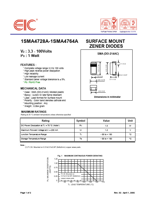
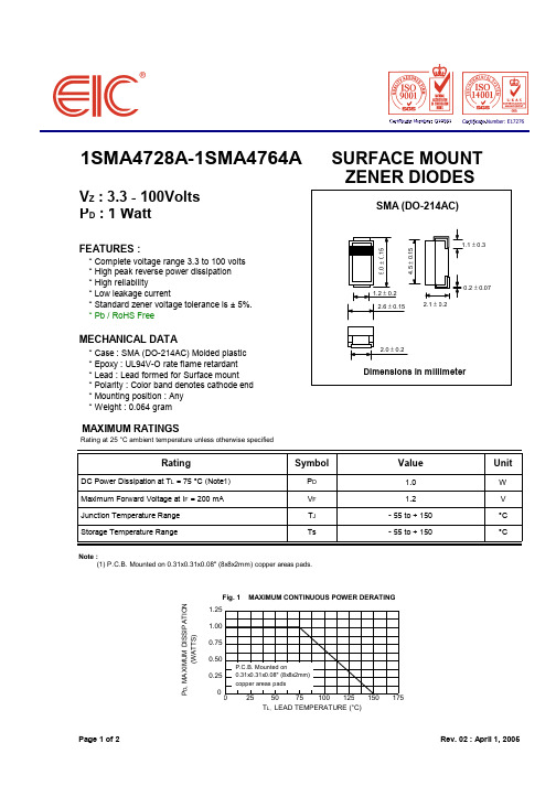
1SMA4728A-1SMA4764A
VZ : 3.3 - 100Volts PD : 1 Watt
FEATURES :
* Complete voltage range 3.3 to 100 volts * High peak reverse power dissipation * High reliability * Low leakage current * Standard zener voltage tolerance is ± 5%. * Pb / RoHS Free
MAXIMUM CONTINUOUS POWER DERATING
P.C.B. Mounted on 0.31x0.31x0.08" (8x8x2mm) copper areas pads
25
50
75
100
125
150
175
TL, LEAD TEMPERATURE (°C)
Page 1 of 2
Rev. 02 : April 1, 2005
Page 2 of 2
1N4737A-A中文资料

1N4728A - 1N4761A1.0W ZENEDIODENote: 1. Valid provided that leads are kept at T L @ 50°C with lead length = 9.5mm (3/8”) from case.2. EC Directive 2002/95/EC (RoHS) revision 13.2.2003. Glass and High Temperature Solder Exemptions Applied where applicable,see EU Directive Annex Notes 5 and 7.Mechanical Data·1.0 Watt Power Dissipation · 3.3V - 75V Nominal Zener Voltage ·Standard V Z Tolerance is 5%·Lead Free Finish, RoHS Compliant (Note 2)·Case: DO-41·Case Material: Glass. UL Flammability Classification Rating 94V-0·Moisture Sensitivity: Level 1 per J-STD-020C ·Terminals: Finish ¾ Sn96.5Ag3.5. Solderable per MIL-STD-202, Method 208·Polarity: Cathode Band ·Marking: Type Number·Weight: 0.35 grams (approximate)FeaturesElectrical Characteristics @ T A = 25°C unless otherwise specifiedNotes: 3. Measured under thermal equilibrium and dc (I ZT) test conditions.4. The Zener impedance is derived from the 60 Hz ac voltage which results when an ac current having an rms value equal to10% of the Zener current (I ZT or I ZK) is superimposed on I ZT or I ZK. Zener impedance is measured at two points to insure asharp knee on the breakdown curve and to eliminate unstable units.Notes: 5. *Add "-A" or "-T" to the appropriate type number in Table 1. Example: 6.2V Zener = 1N4735A-A for ammo pack. 6. For packaging details, visit our website at /datasheets/ap02008.pdf00.20.40.60.81.004080120160200P , T O T A L P O W E R D I S S I P A T I O N (W )d T , AMBIENT TEMPERATURE ( C)A Fig.1 Power Dissipation vs Ambient Temperature0250515202530l, Lead Length (mm)Fig. 2 Typical Thermal Resistance vs. Lead Length10200501001501101001000110100V , ZENER VOLTAGE (V)Z Fig. 4 Typical Zener Impedance vs. Zener Voltage1101001000102030405060C ,D I O DE C A P A C I T A N C E (pF )j V , ZENER VOLTAGE (V)Z Fig.3, Junction Capacitance vs Zener Voltagef = 1MHz T = 25CA V = 0V R V = 2V R V = 5V R V = 20VR V = 30VR Ordering Information(Note 6)IMPORTANT NOTICEDiodes Incorporated and its subsidiaries reserve the right to make modifications, enhancements, improvements, corrections or other changes without further notice to any product herein. Diodes Incorporated does not assume any liability arising out of the application or use of any product described herein; neither does it convey any license under its patent rights, nor the rights of others. The user of products in such applications shall assume all risks of such use and will agree to hold Diodes Incorporated and all the companies whose products are represented on our website, harmless against all damages.LIFE SUPPORTDiodes Incorporated products are not authorized for use as critical components in life support devices or systems without the expressed written approval of the President of Diodes Incorporated.。
1SMA4734A中文资料

Maximum DC Zener Current IZM (mA) 276 252 234 217 193 178 162 146 133 121 110 100 91 83 76 69 61 57 50 45 41 38 34 30 27 25 23 22 19 18 16 14 13 12 11 10 9.0
Maximum Surge Current IRM(2) (mApk) 1380 1260 1190 1070 970 890 810 730 660 605 550 500 454 414 380 344 305 285 250 225 205 190 170 150 135 125 115 110 95 90 80 70 65 60 55 50 45
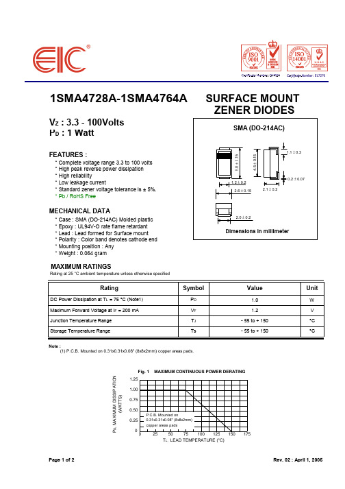
MAXIMUM CONTINUOUS POWER DERATING
P.C.B. Mounted on 0.31x0.31x0.08" (8x8x2mm) copper areas pads
25
50
75
100
125
150
175
TL, LEAD TEMPERATURE (°C)
Page 1 of 2
Rev. 02 : April 1, 2005
ZZT @ IZT ZZK @ IZK (Ω) 10 10 9.0 9.0 8.0 7.0 5.0 2.0 3.5 4.0 4.5 5.0 7.0 8.0 9.0 10 14 16 20 22 23 25 35 40 45 50 60 70 80 95 110 125 150 175 200 250 350 (Ω) 400 400 400 400 500 550 600 700 700 700 700 700 700 700 700 700 700 700 750 750 750 750 750 1000 1000 1000 1000 1500 1500 1500 2000 2000 2000 2000 3000 3000 3000
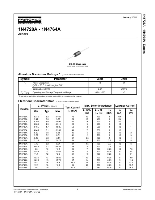
AT91SAM7A3-AU;中文规格书,Datasheet资料
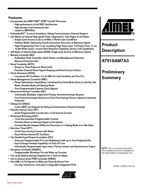
Features Array•Incorporates the ARM7TDMI ® ARM® Thumb® Processor–High-performance 32-bit RISC Architecture–High-density 16-bit Instruction Set–Leader in MIPS/Watt•EmbeddedICE™ In-circuit Emulation, Debug Communication Channel Support•256 Kbytes of Internal High-speed Flash, Organized in 1024 Pages of 256 Bytes –Single Cycle Access at Up to 30 MHz in Worst Case Conditions–Prefetch Buffer Optimizing Thumb Instruction Execution at Maximum Speed–Page Programming Time: 6 ms, Including Page Auto-erase, Full Erase Time: 15 ms –10,000 Write Cycles, 10-year Data Retention Capability, Sector Lock Capabilities •32K Bytes of Internal High-speed SRAM, Single-cycle Access at Maximum Speed •Memory Controller (MC)–Embedded Flash Controller, Abort Status and Misalignment Detection–Memory Protection Unit•Reset Controller (RSTC)–Based on Three Power-on Reset Cells–Provides External Reset Signal Shaping and Reset Sources Status•Clock Generator (CKGR)–Low-power RC Oscillator, 3 to 20 MHz On-chip Oscillator and One PLL•Power Management Controller (PMC)–Power Optimization Capabilities, including Slow Clock Mode (Down to 500 Hz), Idle Mode, Standby Mode and Backup Mode–Four Programmable External Clock Signals•Advanced Interrupt Controller (AIC)–Individually Maskable, Eight-level Priority, Vectored Interrupt Sources–Four External Interrupt Sources and One Fast Interrupt Source, Spurious Interrupt Protected•Debug Unit (DBGU)–2-wire UART and Support for Debug Communication Channel interrupt •Periodic Interval Timer (PIT)–20-bit Programmable Counter plus 12-bit Interval Counter•Windowed Watchdog (WDT)–12-bit key-protected Programmable Counter–Provides Reset or Interrupt Signal to the System–Counter May Be Stopped While the Processor is in Debug Mode or in Idle State •Real-time Timer (RTT)–32-bit Free-running Counter with Alarm–Runs Off the Internal RC Oscillator•Two Parallel Input/Output Controllers (PIO)–Sixty-two Programmable I/O Lines Multiplexed with up to Two Peripheral I/Os–Input Change Interrupt Capability on Each I/O Line–Individually Programmable Open-drain, Pull-up resistor and Synchronous Output •Shutdown Controller (SHDWC)–Programmable Shutdown Pin and Wake-up Circuitry•Two 32-bit Battery Backup Registers for a Total of 8 Bytes•One 8-channel 20-bit PWM Controller (PWMC)•One USB 2.0 Full Speed (12 Mbits per Second) Device Port–On-chip Transceiver, 2376-byte Configurable Integrated FIFOs26042DS–ATARM–14-Dec-06AT91SAM7A3•Nineteen Peripheral DMA Controller (PDC) Channels•Two CAN 2.0B Active Controllers, Supporting 11-bit Standard and 29-bit Extended Identifiers –16 Fully Programmable Message Object Mailboxes, 16-bit Time Stamp Counter •Two 8-channel 10-bit Analog-to-Digital Converter•Three Universal Synchronous/Asynchronous Receiver Transmitters (USART)–Individual Baud Rate Generator, IrDA ® Infrared Modulation/Demodulation–Support for ISO7816 T0/T1 Smart Card, Hardware Handshaking, RS485 Support •Two Master/Slave Serial Peripheral Interfaces (SPI)–8- to 16-bit Programmable Data Length, Four External Peripheral Chip Selects •Three 3-channel 16-bit Timer/Counters (TC)–Three External Clock Inputs, Two Multi-purpose I/O Pins per Channel –Double PWM Generation, Capture/Waveform Mode, Up/Down Capability •Two Synchronous Serial Controllers (SSC)–Independent Clock and Frame Sync Signals for Each Receiver and Transmitter –I²S Analog Interface Support, Time Division Multiplex Support–High-speed Continuous Data Stream Capabilities with 32-bit Data Transfer •One Two-wire Interface (TWI)–Master Mode Support Only, All Two-wire Atmel EEPROM’s Supported •Multimedia Card Interface (MCI)–Compliant with Multimedia Cards and SD Cards–Automatic Protocol Control and Fast Automatic Data Transfers with PDC, MMC and SDCard Compliant •IEEE ® 1149.1 JTAG Boundary Scan on All Digital Pins •Required Power Supplies–Embedded 1.8V Regulator, Drawing up to 130 mA for the Core and the External Components, Enables 3.3V Single Supply Mode–3.3V VDD3V3 Regulator, I/O Lines and Flash Power Supply–1.8V VDD1V8 Output of the Voltage Regulator and Core Power Supply –3V to 3.6V VDDANA ADC Power Supply –3V to 3.6V VDDBU Backup Power Supply •5V-tolerant I/Os•Fully Static Operation: Up to 60 MHz at 1.65V and 85°C Worst Case Conditions •Available in a 100-lead LQFP Green Package36042DS–ATARM–14-Dec-06AT91SAM7A31.DescriptionThe AT91SAM7A3 is a member of a series of 32-bit ARM7™ microcontrollers with an integrated CAN controller. It features a 256-Kbyte high-speed Flash and 32-Kbyte SRAM, a large set of peripherals, including two 2.0B full CAN controllers, and a complete set of system functions min-imizing the number of external components. The device is an ideal migration path for 8-bit microcontroller users looking for additional performance and extended memory.The embedded Flash memory can be programmed in-system via the JTAG-ICE interface. Built-in lock bits protect the firmware from accidental overwrite.The AT91SAM7A3 integrates a complete set of features facilitating debug, including a JTAG Embedded ICE interface, misalignment detector, interrupt driven debug communication channel for user configurable trace on a console, and JTAG boundary scan for board level debug and test.By combining a high-performance 32-bit RISC processor with a high-density 16-bit instruction set, Flash and SRAM memory, a wide range of peripherals including CAN controllers, 10-bit ADC, Timers and serial communication channels, on a monolithic chip, the AT91SAM7A3 is ideal for many compute-intensive embedded control applications.46042DS–ATARM–14-Dec-06AT91SAM7A32.Block DiagramFigure 2-1.AT91SAM7A3 Block Diagram56042DS–ATARM–14-Dec-06AT91SAM7A33.Signal DescriptionTable 3-1.Signal DescriptionSignal NameFunctionTypeActive LevelCommentsPowerVDD3V3 1.8V Voltage Regulator, I/O Lines and Flash Power SupplyPower 3.0V to 3.6V VDDBU Backup I/O Lines Power Supply Power 3V to 3.6V VDDANA Analog Power SupplyPower 3V to 3.6V VDD1V8 1.8V Voltage Regulator Output and Core Power SupplyPower 1.85V typical VDDPLL 1.8V PLL Power Supply Power 1.65V to 1.95VGNDGroundGroundClocks, Oscillators and PLLsXIN Main Oscillator Input Input XOUT Main Oscillator Output Output PLLRC PLL FilterInput PCK0 - PCK3Programmable Clock Output Output SHDWShut-Down Control Output Open Drain.WKUP0 - WKUP1Wake-Up Inputs Input Accept between 0V and VDDBU FWKUPForce Wake UpInputAccept between 0V and VDDBU External pull-up resistor needed.ICE and JTAGTCK T est Clock Input No pull-up resistor TDI T est Data In Input No pull-up resistorTDO T est Data Out Output TMS T est Mode Select Input No pull-up resistor JT AGSELJTAG SelectionInputPull-down resistor Reset/TestNRST Microcontroller Reset I/O Low TSTT est Mode SelectInputHighPull-down resistorDebug UnitDRXD Debug Receive Data Input DTXDDebug Transmit DataOutput66042DS–ATARM–14-Dec-06AT91SAM7A3AICIRQ0 - IRQ3External Interrupt Inputs Input FIQFast Interrupt InputInputPIOP A0 - P A31Parallel IO Controller A I/O Pulled-up input at reset PB0 - PB29Parallel IO Controller BI/OPulled-up input at resetMultimedia Card InterfaceMCCK Multimedia Card Clock Output MCCDAMultimedia Card A Command I/O MCDA0 - MCDA3Multimedia Card A DataI/OUSB Device PortDDM USB Device Port Data - Analog DDPUSB Device Port Data +Analog USARTSCK0 - SCK1 - SCK2Serial Clock I/O TXD0 - TXD1 - TXD2T ransmit Data I/O RXD0 - RXD1 - RXD2Receive Data Input RTS0 - RTS1 - RTS2Request To Send Output CTS0 - CTS1 - CTS2Clear To SendInputSynchronous Serial ControllerTD0 - TD1T ransmit Data Output RD0 - RD1Receive Data Input TK0 - TK1T ransmit Clock I/O RK0 - RK1Receive Clock I/O TF0 - TF1T ransmit Frame Sync I/O RF0 - RF1Receive Frame SyncI/O Timer/CounterTCLK0 - TCLK8External Clock Input Input TIOA0 - TIOA8I/O Line A I/O TIOB0 - TIOB8I/O Line BI/O PWM ControllerPWM0 - PWM7PWM ChannelsOutput Table 3-1.Signal Description (Continued)Signal NameFunctionTypeActive LevelComments76042DS–ATARM–14-Dec-06AT91SAM7A3SPISPI0_MISO SPI1_MISO Master In Slave Out I/O SPI0_MOSI SPI1_MOSI Master Out Slave In I/O SPI0_SPCK SPI1_SPCK SPI Serial ClockI/O SPI0_NPCS0SPI1_NPCS0SPI Peripheral Chip Select 0I/O Low SPI0_NPCS1 - SPI0_NPCS3SPI1_NPCS1 - SPI1_NPCS3SPI Peripheral Chip SelectOutputLowTwo-wire InterfaceTWD T wo-wire Serial Data I/O TWCKT wo-wire Serial ClockI/OAnalog-to-Digital ConverterADC0_AD0 - ADC0_AD7ADC1_AD0 - ADC1_AD7Analog InputsAnalog Digital pulled-up inputs at resetADVREFP Analog Positive Reference Analog ADC0_ADTRG ADC1_ADTRGADC TriggerInputCAN ControllerCANRX0-CANRX1CAN Inputs Input CANTX0-CANTX1CAN OutputsOutput Table 3-1.Signal Description (Continued)Signal NameFunctionTypeActive LevelComments86042DS–ATARM–14-Dec-06AT91SAM7A34.Package4.1100-lead LQFP Package OutlineFigure 4-1shows the orientation of the 100-lead LQFP package. A detailed mechanical descrip-tion is given in the Mechanical Characteristics section of the full datasheet.Figure 4-1.100-lead LQFP Outline (Top View)96042DS–ATARM–14-Dec-06AT91SAM7A34.2PinoutTable 4-1.Pinout in 100-lead LQFP Package1GND 26VDDBU 51P A2076PLLRC 2NRST 27FWKUP 52P A2177VDDANA 3TST 28WKUP053P A2278ADVREFP 4PB1329WKUP154P A2379GND 5PB1230SHDW 55P A2480PB14/ADC0_AD06PB1131GND 56P A2581PB15/ADC0_AD17PB1032P A457P A2682PB16/ADC0_AD28PB933P A558P A2783PB17/ADC0_AD39PB834P A659VDD1V884PB18/ADC0_AD410PB735P A760GND 85PB19/ADC0_AD511PB636P A861VDD3V386PB20/ADC0_AD612PB537P A962P A2887PB21/ADC0_AD713PB438VDD3V363P A2988VDD3V314PB339GND 64P A3089PB22/ADC1_AD015VDD3V340VDD1V865P A3190PB23/ADC1_AD116GND 41P A1066JTAGSEL 91PB24/ADC1_AD217VDD1V842P A1167TDI 92PB25/ADC1_AD318PB243P A1268TMS 93PB26/ADC1_AD419PB144P A1369TCK 94PB27/ADC1_AD520PB045P A1470TDO 95PB28/ADC1_AD621P A046P A1571GND 96PB29/ADC1_AD722P A147P A1672VDDPLL 97DDM 23P A248P A1773XOUT 98DDP 24P A349P A1874XIN 99VDD1V825GND50P A1975GND100VDD3V3106042DS–ATARM–14-Dec-06AT91SAM7A35.Power Considerations5.1Power SuppliesThe AT91SAM7A3 has five types of power supply pins:•VDD3V3 pins. They power the voltage regulator, the I/O lines, the Flash and the USB transceivers; voltage ranges from 3.0V to 3.6V , 3.3V nominal.•VDD1V8 pins. They are the outputs of the 1.8V voltage regulator and they power the logic of the device.•VDDPLL pin. It powers the PLL; voltage ranges from 1.65V to 1.95V , 1.8V typical. They can be connected to the VDD1V8 pin with decoupling capacitor.•VDDBU pin. It powers the Slow Clock oscillator and the Real Time Clock, as well as a part of the System Controller; ranges from 3.0V and 3.6V , 3.3V nominal.•VDDANA pin. It powers the ADC; ranges from 3.0V and 3.6V , 3.3V nominal.No separate ground pins are provided for the different power supplies. Only GND pins are pro-vided and should be connected as shortly as possible to the system ground plane.5.2Voltage RegulatorThe AT91SAM7A3 embeds a voltage regulator that consumes less than 120 µA static current and draws up to 130 mA of output current.Adequate output supply decoupling is mandatory for VDD1V8 (pin 99)to reduce ripple and avoid oscillations. The best way to achieve this is to use two capacitors in parallel: one external 470 pF (or 1 nF) NPO capacitor must be connected between VDD1V8 and GND as close to the chip as possible. One external 3.3 µF (or 4.7 µF) X7R capacitor must be connected between VDD1V8and GND.All other VDD1V8 pins must be externally connected and have a proper decoupling capacitor (at least 100 nF).Adequate input supply decoupling is mandatory for VDD3V3 (pin 100) in order to improve star-tup stability and reduce source voltage drop. The input decoupling capacitor should be placed close to the chip. For example, two capacitors can be used in parallel: 100 nF NPO and 4.7 µF X7R.All other VDD3V3 pins must be externally connected and have a proper decoupling capacitor (at least 100 nF).分销商库存信息: ATMELAT91SAM7A3-AU。
1SMA48AT3中文资料

Figure 5. Steady State Power Derating
1SMA5.0AT3 through 1SMA78AT3
10,000 TJ = 25°C f = 1 MHz Vsig = 50 mVp–p
1,000
MEASURED AT ZERO BIAS
100
MEASURED AT STAND–OFF VOLTAGE, VWM
10 0 40 80 120 160 TA, AMBIENT TEMPERATURE (°C) 200 1 2 5 10 20 50 V(BR), BREAKDOWN VOLTAGE (VOLTS) 100 200
REV 1
© Motorola, Inc. 1996
1SMA5.0AT3 through 1SMA78AT3
MOTOROLA 1
元器件交易网
ELECTRICAL CHARACTERISTICS — continued (VF = 3.5 Volts @ IF = 40 A for all types)
120 = 10 µs 100 80 60 40 20 0 0.001 0.01 0.1 tP, PULSE WIDTH (ms) 1 10 TA = 25°C PW (ID) IS DEFINED AS THE POINT WHERE THE PEAK CURRENT PEAK VALUE DECAYS TO 50% OF Ipp. Ippm HALF VALUE – Ipp/2 10/1000 µs WAVEFORM AS DEFINED BY R.E.A. td 0 1 2 3 t, TIME (ms) 4 5
1SMA5.0AT3 through 1SMA78AT3
1SMA4744A中文资料
Rating at 25 °C ambient temperature unless otherwise specified Nominal Zener
Maximum Zener Impedance IZK (mA) 1.0 1.0 1.0 1.0 1.0 1.0 1.0 1.0 1.0 0.5 0.5 0.5 0.25 0.25 0.25 0.25 0.25 0.25 0.25 0.25 0.25 0.25 0.25 0.25 0.25 0.25 0.25 0.25 0.25 0.25 0.25 0.25 0.25 0.25 0.25 0.25 0.25
Maximum Surge Current IRM(2) (mApk) 1380 1260 1190 1070 970 890 810 730 660 605 550 500 454 414 380 344 305 285 250 225 205 190 170 150 135 125 115 110 95 90 80 70 65 60 55 50 45
Page 2 of 2
Rev. 02 : April 1, 2005
元器件交易网
1SMA4728A-1SMA4764A
VZ : 3.3 - 100Volts PD : 1 Watt
FEATURES :
* Complete voltage range 3.3 to 100 volts * High peak reverse power dissipation * High reliability * Low leakage current * Standard zener voltage tolerance is ± 5%. * Pb / RoHS Free
常用稳压二极管技术参数及老型号代换

常用稳压二极管技术参数及老型号代换型号最大功耗 (mW) 稳定电压(V) 电流(mA) 代换型号国产稳压管日立稳压管HZ4B2 500 3.8 4.0 5 2CW102 2CW21 4B2HZ4C1 500 4.0 4.2 5 2CW102 2CW21 4C1HZ6 500 5.5 5.8 5 2CW103 2CW21A 6B1HZ6A 500 5.2 5.7 5 2CW103 2CW21AHZ6C3 500 6 6.4 5 2CW104 2CW21B 6C3HZ7 500 6.9 7.2 5 2CW105 2CW21CHZ7A 500 6.3 6.9 5 2CW105 2CW21CHZ7B 500 6.7 7.3 5 2CW105 2CW21CHZ9A 500 7.7 8.5 5 2CW106 2CW21DHZ9CTA 500 8.9 9.7 5 2CW107 2CW21EHZ11 500 9.5 11.9 5 2CW109 2CW21GHZ12 500 11.6 14.3 5 2CW111 2CW21HHZ12B 500 12.4 13.4 5 2CW111 2CW21HHZ12B2 500 12.6 13.1 5 2CW111 2CW21H 12B2HZ18Y 500 16.5 18.5 5 2CW113 2CW21JHZ20-1 500 18.86 19.44 2 2CW114 2CW21KHZ27 500 27.2 28.6 2 2CW117 2CW21L 27-3HZT33-02 400 31 33.5 5 2CW119 2CW21MRD2.0E(B) 500 1.88 2.12 20 2CW100 2CW21P 2B1RD2.7E 400 2.5 2.93 20 2CW101 2CW21SRD3.9EL1 500 3.7 4 20 2CW102 2CW21 4B2RD5.6EN1 500 5.2 5.5 20 2CW103 2CW21A 6A1RD5.6EN3 500 5.6 5.9 20 2CW104 2CW21B 6B2RD5.6EL2 500 5.5 5.7 20 2CW103 2CW21A 6B1RD6.2E(B) 500 5.88 6.6 20 2CW104 2CW21BRD7.5E(B) 500 7.0 7.9 20 2CW105 2CW21CRD10EN3 500 9.7 10.0 20 2CW108 2CW21F 11A2RD11E(B) 500 10.1 11.8 15 2CW109 2CW21GRD12E 500 11.74 12.35 10 2CW110 2CW21H 12A1RD12F 1000 11.19 11.77 20 2CW109 2CW21GRD13EN1 500 12 12.7 10 2CW110 2CW21H 12A3RD15EL2 500 13.8 14.6 15 2CW112 2CW21J 12C3RD24E 400 22 25 10 2CW116 2CW21H 24-1RD24F 400 24 28 10 2CW117 2CW21LRD36EL1 500 32 34 15 2CW119 2CW21M 33-2RD57E 500 48 54 10 1DS55-1805Z5.1Y 500 4.94 5.20 2CW103 2CW21A 5C205Z5.6Z 500 5.61 5.91 2CW104 2CW21B 6B205Z6.2Y 500 5.96 6.27 41 2CW104 2CW21B 6C205Z7.5Y 500 7.07 7.45 34 2CW105 2CW21C05Z7.5Z 500 7.3 7.7 34 2CW105 2CW21C 7C205Z9.1Y 500 8.9 9.3 30 2CW107 2CW21E 9C105Z12 500 11.13 12.35 21 2CW110 2CW21H05Z12Z 500 12.0 12.6 20 2CW110 2CW21H 12A305Z13X 500 12.11 12.75 19 2CW110 2CW21H 12A305Z13Z 500 13.5 14.1 18 2CW111 2CW21H 12C205Z13Y 500 12.55 13.21 19 2CW111 2CW21H 12B205Z15 500 14.4 15.0 17 2CW112 2CW21J 15-205Z15Y 500 13.89 14.62 17 2CW111 2CW21H 12C305Z18 500 16.5 18.5 14 2CW113 2CW21J05Z18Y 500 16.82 17.70 14 2CW113 2CW21J 18-1EQA01-11B 500 10.1 11.8 15 2CW109 2CW21GEQA01-12Z 500 11.2 13.1 15 2CW110 2CW21HEQA02-07B 400 6.66 7.01 20 2CW105 2CW21C 7A3EQA02-25A 500 24 25.5 2CW116 2CW21L 24-3TVSQA106SB 500 5.88 6.6 20 2CW104 2CW21BTVSQA111SB 500 10.4 11.6 10 2CW109 2CW21GTVSQA111SE 500 11 11.5 10 2CW109 2CW21G 11C2MA1130 1000 12.4 14.1 5 2CW111 2CW21HMA1330 500 31 35 25 2CW120 2CW21NM4030 500 2.9 3 5 2CW101 2CW21SuPC574JAG 200 31 35 25 2CW120 2CW21NRIMV 135 160 ZDW591N708 0.25 5.6 40 BWA54、2CW28-5.6V1N709 0.25 6.2 40 2CW55/B、BWA55/E1N710 0.25 6.8 36 2CW55A、2CW105-6.8V1N711 0.25 7.5 30 2CW56A、2CW28-7.5V、2CW106-7.5V 1N712 0.25 8.2 30 2CW57/B、2CW106-8.2V1N713 0.25 9.1 27 2CW58A/B、2CW741N714 0.25 10 25 2CW18、2CW59/A/B1N715 0.25 11 20 2CW76、2DW12F.BS31-121N716 0.25 12 20 2CW61/A、2CW77/A1N717 0.25 13 18 2CW62/A、2DW12G1N718 0.25 15 16 2CW112-15V、2CW78/A1N719 0.25 16 15 2CW63/A/B、2DW12H1N720 0.25 18 13 2CW20B、2CW64/B、2CW64-18 1N721 0.25 20 12 2CW65-20、2DW12I、BWA651N722 0.25 22 11 2CW20C、2DW12J1N723 0.25 24 10 WCW116、2DW13A1N724 0.25 27 9 2CW20D、2CW68、BWA68/D1N725 0.40 30 13 2CW119-30V1N726 0.40 33 12 2CW120-33V1N727 0.40 36 11 2CW120-36V1N728 0.40 39 10 2CW121-39V1N748 0.50 3.8~4.0 125 HZ4B21N752 0.50 5.2~5.7 80 HZ6A1N753 0.50 5.8~6.1 80 2CW1321N754 0.5 6.3~6.8 70 H27A1N755 0.50 7.1~7.3 65 HZ7.5EB1N757 0.50 8.9~9.3 52 HZ9C1N962 0.50 9.5~11 45 2CW1371N963 0.50 11~11.5 40 2CW138、HZ12A-21N964 0.50 12~12.5 40 HZ12C-2、MA1130TA1N969 0.50 21~22.5 20 RD245B1N4240A 1 10 100 2CW108-10V、2CW109、2DW5 1N4724A 1 12 76 2DW6A、2CW110-12V1N4728 1 3.3 270 2CW101-3V31N4729 1 3.6 252 2CW101-3V61N4729A 1 3.6 252 2CW101-3V61N4730A 1 3.9 234 2CW102-3V91N4731 1 4.3 217 2CW102-4V31N4731A 1 4.3 217 2CW102-4V31N4732/A 1 4.7 193 2CW102-4V71N4733/A 1 5.1 179 2CW103-5V11N4734/A 1 5.6 162 2CW103-5V61N4735/A 1 6.2 146 1W6V2、2CW104-6V21N4736/A 1 6.8 138 1W6V8、2CW104-6V81N4737/A 1 7.5 121 1W7V5、2CW105-7V51N4738/A 1 8.2 110 1W8V2、2CW106-8V21N4739/A 1 9.1 100 1W9V1、2CW107-9V11N4740/A 1 10 91 2CW286-10V、B563-101N4741/A 1 11 83 2CW109-11V、2DW61N4742/A 1 12 76 2CW110-12V、2DW6A1N4743/A 1 13 69 2CW111-13V、2DW6B、BWC114D 1N4744/A 1 15 57 2CW112-15V、2DW6D1N4745/A 1 16 51 2CW112-16V、2DW6E1N4746/A 1 18 50 2CW113-18V、1W18V1N4747/A 1 20 45 2CW114-20V、BWC115E1N4748/A 1 22 41 2CW115-22V、1W22V1N4749/A 1 24 38 2CW116-24V、1W24V1N4750/A 1 27 34 2CW117-27V、1W27V1N4751/A 1 30 30 2CW118-30V、1W30V、2DW19F 1N4752/A 1 33 27 2CW119-33V、1W33V1N4753 0.5 36 13 2CW120-36V、1/2W36V1N4754 0.5 39 12 2CW121-39V、1/2W39V1N4755 0.5 43 12 2CW122-43V、1/2W43V1N4756 0.5 47 10 2CW122-47V、1/2W47V1N4757 0.5 51 9 2CW123-51V、1/2W51V1N4758 0.5 56 8 2CW124-56V、1/2W56V1N4759 0.5 62 8 2CW124-62V、1/2W62V1N4760 0.5 68 7 2CW125-68V、1/2W68V1N4761 0.5 75 6.7 2CW126-75V、1/2W75V1N4762 0.5 82 6 2CW126-82V、1/2W82V1N4763 0.5 91 5.6 2CW127-91V、1/2W91V1N4764 0.5 100 5 2CW128-100V、1/2W100V1N5226/A 0.5 3.3 138 2CW51-3V3、2CW52261N5227/A/B 0.5 3.6 126 2CW51-3V6、2CW52271N5228/A/B 0.5 3.9 115 2CW52-3V9、2CW52281N5229/A/B 0.5 4.3 106 2CW52-4V3、2CW52291N5230/A/B 0.5 4.7 97 2CW53-4V7、2CW52301N5231/A/B 0.5 5.1 89 2CW53-5V1、2CW52311N5232/A/B 0.5 5.6 81 2CW103-5.6、2CW52321N5233/A/B 0.5 6 76 2CW104-6V、2CW52331N5234/A/B 0.5 6.2 73 2CW104-6.2V、2CW52341N5235/A/B 0.5 6.8 67 2CW105-6.8V、2CW5235型号稳压值(V) 稳定电流 (MA) 功率(mW) 型号稳压值(V) 稳定电流 (MA) 功率(mW) MA1030 3 5 400 MA2180 18 20 1000MA1033 3.3 5 400 MA2200 20 20 1000MA1036 3.6 5 400 MA2220 22 10 1000MA1039 3.9 5 400 MA2240 24 10 1000MA1043 4.3 5 400 MA2270 27 5 1000MA1047 4.7 5 400 MA2300 30 5 1000MA1051 5.1 5 400 MA2330 33 5 1000MA1056 5.6 5 400 MA2360 36 5 1000MA1062 6.2 5 400 MA3047 4.7 5 150MA1068 6.8 5 400 MA3051 5.1 5 150MA1075 7.5 5 400 MA3056 5.6 5 150MA1082 8.2 5 400 MA3062 6.2 5 150MA1091 9.1 5 400 MA3082 8.2 5 150MA1100 10 5 400 MA3091 9.1 5 150MA1110 11 5 400 MA3100 10 5 150MA1114 11.4 10 400 MA3110 11 5 150MA1120 12 5 400 MA3120 12 5 150MA1130 13 5 400 MA3130 13 5 150MA1140 14 5 400 MA3150 15 5 150MA1150 15 5 400 MA3160 16 5 150MA1160 16 5 400 MA3180 18 5 150MA1180 18 5 400 MA3200 20 5 150MA1200 20 5 400 MA3220 22 5 150MA1220 22 5 400 MA3240 24 5 150MA1240 24 5 400 MA3270 27 2 150MA1270 27 2 400 MA3300 30 2 150MA1300 30 2 400 MA3330 33 2 150MA1330 33 2 400 MA3360 36 2 150MA1360 36 2 400 MA4030 3 5 370MA2051 5.1 40 1000 MA4033 3.3 5 370MA2056 5.6 40 1000 MA4036 3.6 5 370MA2062 6.2 40 1000 MA4039 3.9 5 370 MA2068 6.8 40 1000 MA4043 4.3 5 370 MA2075 7.5 40 1000 MA4047 4.7 5 370 MA2082 8.2 40 1000 MA4051 5.1 5 370 MA2091 9.1 40 1000 MA4056 5.6 5 370 MA2100 10 40 1000 MA4062 6.2 5 370 MA2110 11 5 1000 MA4068 6.8 5 370MA2120 12 5 1000 MA4075 7.5 5 370MA2130 13 5 1000 MA4082 8.2 5 370MA2150 15 5 1000 MA4091 9.1 5 370MA2160 16 5 1000 MA4100 10 5 370MA4110 11 5 370 BZX55C6V8 6.8 5 500 MA4120 12 5 370 BZX55C7V5 7.5 5 500 MA4130 13 5 370 BZX55C8V2 8.2 5 500 MA4140 14 5 370 BZX55C9V1 9.1 5 500 MA4150 15 5 370 BZX55C10 10 5 500MA4160 16 5 370 BZX55C11 11 5 500MA4180 18 5 370 BZX55C12 12 5 500MA4200 20 5 370 BZX55C13 13 5 500MA4220 22 5 370 BZX55C15 15 5 500MA4240 24 5 370 BZX55C16 16 5 500MA4270 27 2 370 BZX55C18 18 5 500MA4300 30 2 370 BZX55C20 20 5 500MA4330 33 2 370 BZX55C22 22 5 500MA4360 36 2 370 BZX55C24 24 5 500MA5047 4.7 5 500 BZX55C27 27 5 500 MA5051 5.1 5 500 BZX55C30 30 5 500 MA5056 5.6 5 500 BZX55C33 33 5 500 MA5062 6.2 5 500 BZX55C36 36 5 500 MA5068 6.8 5 500 BZX55C39 39 5 500 MA5075 7.5 5 500 BZX55C43 43 2.5 500 MA5082 8.2 5 500 BZX55C47 47 2.5 500 MA5091 9.1 5 500 BZX55C51 51 2.5 500 MA5100 10 5 500 BZX55C56 56 2.5 500 MA5110 11 5 500 BZX55C62 62 2.5 500 MA5120 12 5 500 BZX85C2V7 2.7 80 1300 MA5130 13 5 500 BZX85C3V0 3.0 80 1300MA5160 16 5 500 BZX85C3V6 3.6 70 1300MA5180 18 5 500 BZX85C3V9 3.9 60 1300MA5200 20 5 500 BZX85C4V3 4.3 50 1300MA5240 24 5 500 BZX85C4V7 4.7 45 1300 BZX55C2V4 2.4 5 500 BZX85C5V1 5.1 45 1300 BZX55C2V7 2.7 5 500 BZX85C5V6 5.6 45 1300 BZX55C3V0 3.0 5 500 BZX85C6V2 6.2 35 1300 BZX55C3V3 3.3 5 500 BZX85C6V8 6.8 35 1300 BZX55C3V6 3.6 5 500 BZX85C7V5 7.5 35 1300 BZX55C3V9 3.9 5 500 BZX85C8V2 8.2 25 1300BZX55C4V3 4.3 5 500 BZX85C9V1 9.1 25 1300 BZX55C4V7 4.7 5 500 BZX85C10 10 25 1300 BZX55C5V1 5.1 5 500 BZX85C11 11 20 1300 BZX55C5V6 5.6 5 500 BZX85C12 12 20 1300 BZX55C6V2 6.2 5 500 BZX85C13 13 20 1300 BZX85C15 15 15 1300 BZX79A9V1 9.1 5 400 BZX85C16 16 15 1300 BZX79A10 10 5 400 BZX85C18 18 15 1300 BZX79A11 11 5 400 BZX85C20 20 10 1300 BZX79A12 12 5 400 BZX85C22 22 10 1300 BZX79A13 13 5 400 BZX85C24 24 10 1300 BZX79A15 15 5 400 BZX85C27 27 8 1300 BZX79A16 16 5 400BZX85C30 30 8 1300 BZX79A18 18 5 400BZX85C33 33 8 1300 BZX79A20 20 5 400BZX85C36 36 8 1300 BZX79A22 22 5 400BZX85C39 39 6 1300 BZX79A24 24 5 400BZX85C43 43 6 1300 BZX79A27 27 2 400BZX85C47 47 4 1300 BZX79A30 30 2 400BZX85C51 51 4 1300 BZX79A33 33 2 400BZX85C56 56 4 1300 BZX79A36 36 2 400BZX85C62 62 4 1300 BZX79A39 39 2 400BZX55C68 68 2.5 500 BZX79A43 43 2 400 BZX55C75 75 2.5 500 BZX79A47 47 2 400 BZX55C82 82 2.5 500 BZX79A51 51 2 400 BZX55C91 91 1 500 BZX79A56 56 2 400BZX55C110 110 1 500 BZX79A68 68 2 400BZX55C120 120 1 500 BZX79A75 75 2 400BZX55C130 130 1 500 BZX79C2V4 2.4 5 500BZX55C150 150 1 500 BZX79C2V7 2.7 5 500BZX55C160 160 1 500 BZX79C3V0 3.0 5 500BZX55C180 180 1 500 BZX79C3V3 3.3 5 500BZX55C200 200 1 500 BZX79C3V6 3.6 5 500BZX79A2V4 2.4 5 400 BZX79C3V9 3.9 5 500BZX79A2V7 2.7 5 400 BZX79C4V3 4.3 5 500BZX79A3V0 3.0 5 400 BZX79C4V7 4.7 5 500BZX79A3V3 3.3 5 400 BZX79C5V1 5.1 5 500BZX79A3V6 3.6 5 400 BZX79C5V6 5.6 5 500BZX79A3V9 3.9 5 400 BZX79C6V2 6.2 5 500BZX79A4V3 4.3 5 400 BZX79C6V8 6.8 5 500BZX79A4V7 4.7 5 400 BZX79C7V5 7.5 5 500BZX79A5V1 5.1 5 400 BZX79C8V2 8.2 5 500BZX79A5V6 5.6 5 400 BZX79C9V1 9.1 5 500BZX79A6V2 6.2 5 400 BZX79C10 10 5 500BZX79A6V8 6.8 5 400 BZX79C11 11 5 500BZX79A7V5 7.5 5 400 BZX79C12 12 5 500BZX79A8V2 8.2 5 400 BZX79C13 13 5 500整流二极管:整流二极管是面接触型的,多采用硅材料构成。
常用稳压管型号

常用稳压型号参数查询DZ是稳压管的电器编号,1N4148就是一个0.6V的稳压管,下面是稳压管上的编号对应的稳压值,有些小的稳压管也会在管体上直接标稳压电压,如5V6就是5.6V的稳压管;美标稳压二极管型号:HITACHI日立:HITACHI日立0.5W稳压二极管型号参数稳压HZ3A1 2.5~2.7VHZ3A2 2.6~2.8VHZ3A3 2.6~2.9VHZ3B1 2.8~3.0VHZ3B2 2.9~3.1VHZ3B3 3.0~3.2V线性稳压器件输入输出电流相等,压降3V以上型号稳压V 最大输出电流可替代型号79L05 -5V 100mA79L06 -6V 100mA79L08 -8V 100mALM7805 5V 1A L7805,LM340T5 LM7806 6V 1A L7806LM7808 8V 1A L7808LM7809 9V 1A L7809LM7812 12V 1A L7812,LM340T12 LM7815 15V 1A L7815,LM340T15 LM7818 18V 1A L7815LM7824 24V 1A L7824LM7905 -5V 1A L7905LM7906 -6V 1A L7906,KA7906 LM7908 -8V 1A L7908LM7909 -9V 1A L7909LM7912 -12V 1A L7912LM7915 -15V 1A L7915LM7918 -18V 1A L7918LM7924 -24V 1A L792478L05 5V 100mA78L06 6V 100mA78L08 8V 100ma78L09 9V 100ma78L12 12V 100ma78L15 15V 100ma78L18 18V 100ma78L24 24V 100ma开关稳压器件电压转换效率高型号说明最大输出电流LM1575T-3.3 3.3V简易开关电源稳压器 1ALM1575T-5.0 5V简易开关电源稳压器 1A LM1575T-12 12V简易开关电源稳压器 1A LM1575T-15 15V简易开关电源稳压器 1A LM1575T-ADJ 简易开关电源稳压器可调1.23V~37V 1ALM1575HVT-3.3 3.3V简易开关电源稳压器 1A LM1575HVT-5.0 5V简易开关电源稳压器 1A LM1575HVT-12 12V简易开关电源稳压器 1ALM1575HVT-15 15V简易开关电源稳压器 1ALM1575HVT-ADJ 简易开关电源稳压器可调1.23V~37V 1ALM2575T-3.3 3.3V简易开关电源稳压器 1A LM2575T-5.0 5V简易开关电源稳压器 1A LM2575T-12 12V简易开关电源稳压器 1A LM2575T-15 15V简易开关电源稳压器 1A LM2575T-ADJ 简易开关电源稳压器可调1.23V~ 37V 1ALM2575HVT-3.3 3.3V简易开关电源稳压器 1A LM2575HVT-5.0 5V简易开关电源稳压器 1A LM2575HVT-12 12V简易开关电源稳压器 1A LM2575HVT-15 15V简易开关电源稳压器 1A LM2575HVT-ADJ 简易开关电源稳压器可调1.23V~37V 1ALM2576T-3.3 3.3V简易开关电源稳压器 3A LM2576T-5.0 5.0V简易开关电源稳压器 3A LM2576T-12 12V简易开关电源稳压器 3A LM2576T-15 15V简易开关电源稳压器 3A LM2576T-ADJ 简易开关电源稳压器可调1.23V~37V 3ALM2576HVT-3.3 3.3V简易开关电源稳压器 3A LM2576HVT-5.0 5.0V简易开关电源稳压器 3ALM2576HVT-12 12V简易开关电源稳压器 3ALM2576HVT-15 15V简易开关电源稳压器 3ALM2576HVT-ADJ 简易开关电源稳压器可调1.23V~37V 3A。
1SMA4742A资料
ZZT @ IZT ZZK @ IZK (Ω) 10 10 9.0 9.0 8.0 7.0 5.0 2.0 3.5 4.0 4.5 5.0 7.0 8.0 9.0 10 14 16 20 22 23 25 35 40 45 50 60 70 80 95 110 125 150 175 200 250 350 (Ω) 400 400 400 400 500 550 600 700 700 700 700 700 700 700 700 700 700 700 750 750 750 750 750 1000 1000 1000 1000 1500 1500 1500 2000 2000 2000 2000 3000 3000 3000
Maximum Reverse Leakage Current (µA) 100 100 50 10 10 10 10 10 50 50 50 50 50 50 5.0 5.0 5.0 5.0 5.0 5.0 5.0 5.0 5.0 5.0 5.0 5.0 5.0 5.0 5.0 5.0 5.0 5.0 5.0 5.0 5.0 5.0 5.0 IR @ VR (V) 1.0 1.0 1.0 1.0 1.0 1.0 2.0 3.0 4.0 5.0 6.0 7.0 7.6 8.4 9.1 9.9 11.4 12.2 13.7 15.2 16.7 18.2 20.6 22.8 25.1 27.4 29.7 32.7 35.8 38.8 42.6 47.1 51.7 56.0 62.2 69.2 76.0
元器件交易网
ELECTRICAL CHARACTERISTICS
Type Device Marking
728A 729A 730A 731A 732A 733A 734A 735A 736A 737A 738A 739A 740A 741A 742A 743A 744A 745A 746A 747A 748A 749A 750A 751A 752A 753A 754A 755A 756A 757A 758A 759A 760A 761A 762A 763A 764A Voltage VZ @ IZT (V) 3.3 3.6 3.9 4.3 4.7 5.1 5.6 6.2 6.8 7.5 8.2 9.1 10 11 12 13 15 16 18 20 22 24 27 30 33 36 39 43 47 51 56 62 68 75 82 91 100 IZT (mA) 76.0 69.0 64.0 58.0 53.0 49.0 45.0 41.0 37.0 34.0 31.0 28.0 25.0 23.0 21.0 19.0 17.0 15.5 14.0 12.5 11.5 10.5 9.5 8.5 7.5 7.0 6.5 6.0 5.5 5.0 4.5 4.0 3.7 3.3 3.0 2.8 2.5
1SMA4750A中文资料
Maximum Surge Current IRM(2) (mApk) 1380 1260 1190 1070 970 890 810 730 660 605 550 500 454 414 380 344 305 285 250 225 205 190 170 150 135 125 115 110 95 90 80 70 65 60 55 50 45
Notes : (1) The type number listed have a standard tolerance on the nominal zener voltage of ± 5%. (2) The revese surge current is a non-repetitive, 8.3ms pulse width square wave or equivalent sine-wave superimposed on IZT per JEDEC Method
元器件交易网
ELECTRICAL CHARACTERISTICS
Type Device Marking
728A 729A 730A 731A 732A 733A 734A 735A 736A 737A 738A 739A 740A 741A 742A 743A 744A 745A 746A 747A 748A 749A 750A 751A 752A 753A 754A 755A 756A 757A 758A 759A 760A 761A 762A 763A 764A Voltage VZ @ IZT (V) 3.3 3.6 3.9 4.3 4.7 5.1 5.6 6.2 6.8 7.5 8.2 9.1 10 11 12 13 15 16 18 20 22 24 27 30 33 36 39 43 47 51 56 62 68 75 82 91 100 IZT (mA) 76.0 69.0 64.0 58.0 53.0 49.0 45.0 41.0 37.0 34.0 31.0 28.0 25.0 23.0 21.0 19.0 17.0 15.5 14.0 12.5 11.5 10.5 9.5 8.5 7.5 7.0 6.5 6.0 5.5 5.0 4.5 4.0 3.7 3.3 3.0 2.8 2.5
【8A版】常用稳压管型号

常用稳压型号参数查询DZ是稳压管的电器编号,1N4148就是一个0.6V的稳压管,下面是稳压管上的编号对应的稳压值,HITACHI(日立):型号参数稳压HZ3A1 2.5~2.7VHZ3A2 2.6~2.8VHZ3A3 2.6~2.9VHZ3B1 2.8~3.0VHZ3B2 2.9~3.1VHZ3B3 3.0~3.2V线性稳压器件(输入输出电流相等,压降3V以上) 型号稳压(V)最大输出电流可替代型号79L05-5V100mA79L06-6V100mA79L08-8V100mALM78055V1AL7805,LM340T5LM78066V1AL7806LM78088V1AL7808LM78099V1AL7809LM781212V1AL7812,LM340T12LM781515V1AL7815,LM340T15LM781818V1AL7815LM782424V1AL7824LM7905-5V1AL7905LM7906-6V1AL7906,KA7906LM7908-8V1AL7908LM7909-9V1AL7909LM7912-12V1AL7912LM7915-15V1AL7915LM7918-18V1AL7918LM7924-24V1AL792478L055V100mA78L066V100mA78L088V100ma78L099V100ma78L1212V100ma78L1515V100ma78L1818V100ma78L2424V100ma开关稳压器件(电压转换效率高)型号说明最大输出电流LM1575T-3.33.3V简易开关电源稳压器1ALM1575T-5.05V简易开关电源稳压器1ALM1575T-1212V简易开关电源稳压器1ALM1575T-1515V简易开关电源稳压器1ALM1575T-ADJ简易开关电源稳压器(可调1.23V~37V)1ALM1575HVT-3.33.3V简易开关电源稳压器1ALM1575HVT-5.05V简易开关电源稳压器1ALM1575HVT-1212V简易开关电源稳压器1ALM1575HVT-1515V简易开关电源稳压器1ALM1575HVT-ADJ简易开关电源稳压器(可调1.23V~37V)1ALM2575T-3.33.3V简易开关电源稳压器1ALM2575T-5.05V简易开关电源稳压器1ALM2575T-1212V简易开关电源稳压器1ALM2575T-ADJ简易开关电源稳压器(可调1.23V~37V)1A LM2575HVT-3.33.3V简易开关电源稳压器1ALM2575HVT-5.05V简易开关电源稳压器1ALM2575HVT-1212V简易开关电源稳压器1ALM2575HVT-1515V简易开关电源稳压器1ALM2575HVT-ADJ简易开关电源稳压器(可调1.23V~37V)1A LM2576T-3.33.3V简易开关电源稳压器3ALM2576T-5.05.0V简易开关电源稳压器3ALM2576T-1212V简易开关电源稳压器3ALM2576T-1515V简易开关电源稳压器3ALM2576T-ADJ简易开关电源稳压器(可调1.23V~37V)3A LM2576HVT-3.33.3V简易开关电源稳压器3ALM2576HVT-5.05.0V简易开关电源稳压器3ALM2576HVT-1212V简易开关电源稳压器3ALM2576HVT-1515V简易开关电源稳压器3ALM2576HVT-ADJ简易开关电源稳压器(可调1.23V~37V)3A。
1n4733a稳压二极管参数

1n4733a稳压二极管参数
1n4733a稳压二极管是主要提供电子设备供电稳压输出的重要组件。
它非常常用,可以广泛应用于各类电子产品,可以每次运行恒流、恒压、恒功率等。
1n4733a稳压二极管有一定的参数要求,型号为1n4733a。
静态雪崩反向电压为 3.3V,正向电流为500mA,正向电感为5uH,正向压正负电压为2.48V~3.0V,工作温度为-55~+155℃。
1n4733a稳压二极管的极性要求简单明了,反向极为负极,正向极为正极,反向电流为500mA,工作电压为2.7V-5.5V。
1n4733a稳压二极管的封装非常多样,如TO-92、SOT-89、SOT-23和SOT-223等。
它们可以用于各种环境,这样它不仅可以满足设计的元器件尖峰电压要求,而且可以实现电子产品的小型化,重复使用稳定、可靠,使用寿命可长达几十年。
1n4733a稳压二极管也有一定的注意事项,如与晶体管同时使用时,要求风扇有效空气流量要大于0.45m^3/min、噪音小于30dB,确保它的可靠性、长久的使用寿命。
1n4733a稳压二极管是一种供电模块,它具有参数要求非常严格、工作温度范围较大和易装配、相对稳定等特点,它受到很多电子设备制造商的青睐,可以用于各种现代电子设备中。
IN4731A中文资料

For BZXyy series: Large Die Identification character
6.0 Fourth Line: Date Code - Two Digit - Six Weeks Date Code Where: X represents the last digit of the calendar year Y represents the Six weeks numeric code
7.0 Devices shall be marked as required in the device specification (PID or FSC Test Spec).
8.0 Maximum no. of marking lines: 5
9.0 Maximum no. of digits per line: 3
F
1st line: F - Fairchild Logo
47
2nd line: Device Name - 3rd to 4th characters of device name for 1Nxx series
or 4th to 6th characters for BZXyy series
36
0.25
22
750
0.25
Units
W
mW/°C °C
Leakage Current
IR
VR
(µA)
(V)
100
1
100
1
50
1
10
1
10
1
10
元件型号1N4732(Daya Electric)中文数据手册「EasyDatasheet」
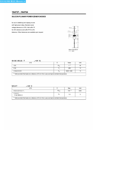
Max. 0.7
Max. 2.8
Min. 25.4
B lac k Cathode Band
B lac k Part No.
XXX
Max. 4.2
Min. 25.4
Glass Case DO-41 尺寸(mm)
绝对最大额定值(T
a = 25 O C)
参数
符
Value
Unit
功耗
P tot
1 1)
W
结温
22
750
0.25
5
15.2
225
1N4748
22
11.5
23
750
0.25
5
16.7
205
1N4749
24
10.5
25
750
0.25
5
18.2
190
1N4750
27
9.5
35
750
0.25
5
20.6
170
1N4751
30
8.5
40
1000
0.25
5
22.8
150
1N4752
33
7.5
45
1000
0.25
700
1
10
3
730
1N4736
6.8
37
3.5
700
1
10
4
660
1N4737
7.5
34
4
700
0.5
10
5
605
1N4738
8.2
31
4.5
700
0.5
10
6
IN4733A中文资料
77.9
82
86.1
86.45
91
95.55
95
100
105
Test Current IZ (mA)
11.5 10.5 9.5 8.5 7.5
7 6.5 6 5.5 5
4.5 4 3.7 3.3 3
2.8 2.5
Max. Zener Impedance
ZZ @ IZ ZZK @ IZK (Ω) IZK (Ω) (mA)
47 47 47 47 47
47 47 47 47 47
47 47 47 47 47
47 47 47 47 47
47 47
Line 3
28 29 30 31 32
33 34 35 36 37
38 39 40 41 42
43 44 45 46 47
48 49 50 51 52
53 54 55 56 57
For BZxx series: 4th to 6th characters of the device name. 4.0 Third Line: Device name - For 1Nxx series: 5th to 6th characters of the device name.
For BZXyy series: Voltage rating 5.0 Third Line: Device name - For 1Nxx series: 7th to 8th characters of the device name.
10.0 FSC logo must be 20 % taller than the alphanumeric marking and should occupy the 2 characters of the specified line.
- 1、下载文档前请自行甄别文档内容的完整性,平台不提供额外的编辑、内容补充、找答案等附加服务。
- 2、"仅部分预览"的文档,不可在线预览部分如存在完整性等问题,可反馈申请退款(可完整预览的文档不适用该条件!)。
- 3、如文档侵犯您的权益,请联系客服反馈,我们会尽快为您处理(人工客服工作时间:9:00-18:30)。
Page 2 of 2
Rev. 02 : April 1, 2005
Maximum Reverse Leakage Current (µA) 100 100 50 10 10 10 10 10 50 50 50 50 50 50 5.0 5.0 5.0 5.0 5.0 5.0 5.0 5.0 5.0 5.0 5.0 5.0 5.0 5.0 5.0 5.0 5.0 5.0 5.0 5.0 5.0 5.0 5.0 IR @ VR (V) 1.0 1.0 1.0 1.0 1.0 1.0 2.0 3.0 4.0 5.0 6.0 7.0 7.6 8.4 9.1 9.9 11.4 12.2 13.7 15.2 16.7 18.2 20.6 22.8 25.1 27.4 29.7 32.7 35.8 38.8 42.6 47.1 51.7 56.0 62.2 69.2 76.0
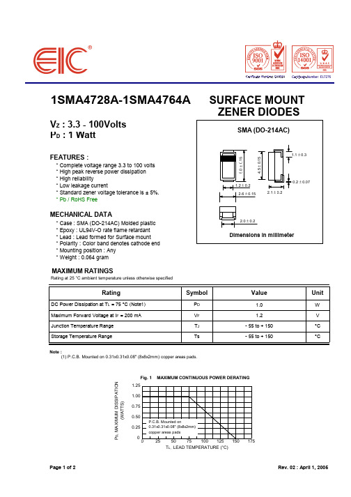
MAXIMUM CONTINUOUS POWER DERATING
P.C.B. Mounted on 0.31x0.31x0.08" (8x8x2mm) copper areas pads
25
50
75
Hale Waihona Puke 100125150
175
TL, LEAD TEMPERATURE (°C)
Page 1 of 2
Rev. 02 : April 1, 2005
元器件交易网
ELECTRICAL CHARACTERISTICS
Type Device Marking
728A 729A 730A 731A 732A 733A 734A 735A 736A 737A 738A 739A 740A 741A 742A 743A 744A 745A 746A 747A 748A 749A 750A 751A 752A 753A 754A 755A 756A 757A 758A 759A 760A 761A 762A 763A 764A Voltage VZ @ IZT (V) 3.3 3.6 3.9 4.3 4.7 5.1 5.6 6.2 6.8 7.5 8.2 9.1 10 11 12 13 15 16 18 20 22 24 27 30 33 36 39 43 47 51 56 62 68 75 82 91 100 IZT (mA) 76.0 69.0 64.0 58.0 53.0 49.0 45.0 41.0 37.0 34.0 31.0 28.0 25.0 23.0 21.0 19.0 17.0 15.5 14.0 12.5 11.5 10.5 9.5 8.5 7.5 7.0 6.5 6.0 5.5 5.0 4.5 4.0 3.7 3.3 3.0 2.8 2.5
ZZT @ IZT ZZK @ IZK (Ω) 10 10 9.0 9.0 8.0 7.0 5.0 2.0 3.5 4.0 4.5 5.0 7.0 8.0 9.0 10 14 16 20 22 23 25 35 40 45 50 60 70 80 95 110 125 150 175 200 250 350 (Ω) 400 400 400 400 500 550 600 700 700 700 700 700 700 700 700 700 700 700 750 750 750 750 750 1000 1000 1000 1000 1500 1500 1500 2000 2000 2000 2000 3000 3000 3000
Symbol
PD VF TJ Ts
Value
1.0 1.2 - 55 to + 150 - 55 to + 150
Unit
W V °C °C
Note : (1) P.C.B. Mounted on 0.31x0.31x0.08" (8x8x2mm) copper areas pads.
Fig. 1 PD, MAXIMUM DISSIPATION (WATTS) 1.25 1.00 0.75 0.50 0.25 0 0
元器件交易网
1SMA4728A-1SMA4764A
VZ : 3.3 - 100Volts PD : 1 Watt
FEATURES :
* Complete voltage range 3.3 to 100 volts * High peak reverse power dissipation * High reliability * Low leakage current * Standard zener voltage tolerance is ± 5%. * Pb / RoHS Free
1SMA4728A 1SMA4729A 1SMA4730A 1SMA4731A 1SMA4732A 1SMA4733A 1SMA4734A 1SMA4735A 1SMA4736A 1SMA4737A 1SMA4738A 1SMA4739A 1SMA4740A 1SMA4741A 1SMA4742A 1SMA4743A 1SMA4744A 1SMA4745A 1SMA4746A 1SMA4747A 1SMA4748A 1SMA4749A 1SMA4750A 1SMA4751A 1SMA4752A 1SMA4753A 1SMA4754A 1SMA4755A 1SMA4756A 1SMA4757A 1SMA4758A 1SMA4759A 1SMA4760A 1SMA4761A 1SMA4762A 1SMA4763A 1SMA4764A
SURFACE MOUNT ZENER DIODES
SMA (DO-214AC)
5.0 ± 0.15
4.5 ± 0.15
1.1 ± 0.3
1.2 ± 0.2 2.6 ± 0.15 2.1 ± 0.2
0.2 ± 0.07
MECHANICAL DATA
* Case : SMA (DO-214AC) Molded plastic * Epoxy : UL94V-O rate flame retardant * Lead : Lead formed for Surface mount * Polarity : Color band denotes cathode end * Mounting position : Any * Weight : 0.064 gram
Maximum Surge Current IRM(2) (mApk) 1380 1260 1190 1070 970 890 810 730 660 605 550 500 454 414 380 344 305 285 250 225 205 190 170 150 135 125 115 110 95 90 80 70 65 60 55 50 45
Notes : (1) The type number listed have a standard tolerance on the nominal zener voltage of ± 5%. (2) The revese surge current is a non-repetitive, 8.3ms pulse width square wave or equivalent sine-wave superimposed on IZT per JEDEC Method
2.0 ± 0.2
Dimensions in millimeter
MAXIMUM RATINGS
Rating at 25 °C ambient temperature unless otherwise specified
Rating
DC Power Dissipation at TL = 75 °C (Note1) Maximum Forward Voltage at IF = 200 mA Junction Temperature Range Storage Temperature Range
Maximum DC Zener Current IZM (mA) 276 252 234 217 193 178 162 146 133 121 110 100 91 83 76 69 61 57 50 45 41 38 34 30 27 25 23 22 19 18 16 14 13 12 11 10 9.0
Rating at 25 °C ambient temperature unless otherwise specified Nominal Zener
Maximum Zener Impedance IZK (mA) 1.0 1.0 1.0 1.0 1.0 1.0 1.0 1.0 1.0 0.5 0.5 0.5 0.25 0.25 0.25 0.25 0.25 0.25 0.25 0.25 0.25 0.25 0.25 0.25 0.25 0.25 0.25 0.25 0.25 0.25 0.25 0.25 0.25 0.25 0.25 0.25 0.25
