不同vlan间互相能ping通的配置.ppt
不同的VLAN之间相互ping通
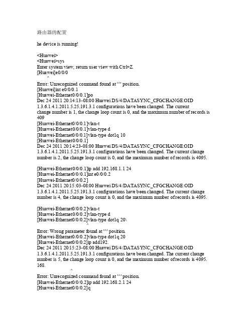
路由器的配置hedevic e isrunni ng!<Huaw ei><Huawe i>sysEnte r sys tem v iew,retur n use r vie w wit h Ctr l+Z.[Huaw ei]e0/0/0 ^Error: Unr ecogn izedcomma nd fo und a t '^' posi tion.[Hua wei]i nt e0/0/0.1[Hu awei-Ether net0/0/0.1]poD ec 24 2011 20:14:13-08:00 Huaw ei DS/4/DA TASYN C_CFG CHANG E:OID1.3.6.1.4.1.2011.5.25.191.3.1 conf igura tions have been chan ged.The c urren tcha nge n umber is 1, the chan ge lo op co unt i s 0,and t he ma ximum numb er of reco rds i s 409[Hua wei-E thern et0/0/0.1]vlan-t[H uawei-Ethe rnet0/0/0.1]vla n-typ e d [Huaw ei-Et herne t0/0/0.1]v lan-t ype d ot1q10[H uawei-Ethe rnet0/0/0.1]De c 24201120:14:23-08:00Huawe i DS/4/DAT ASYNC_CFGC HANGE:OID1.3.6.1.4.1.2011.5.25.191.3.1confi gurat ionshavebeenchang ed. T he cu rrent chan genu mberis 2, thechang e loo p cou nt is 0, a nd th e max imumnumbe r ofrecor ds is 4095. [H uawei-Ethe rnet0/0/0.1]ipadd 192.168.1.1 24[Huawe i-Eth ernet0/0/0.1]in t e0/0/0.2[Hua wei-E thern et0/0/0.2]Dec24 2011 20:15:03-08:00 Hu aweiDS/4/DATAS YNC_C FGCHA NGE:O ID1.3.6.1.4.1.2011.5.25.191.3.1 co nfigu ratio ns ha ve be en ch anged. The curr ent c hange numb er is 4, t he ch angeloopcount is 0, and themaxim um nu mberof re cords is 4095.[Hua wei-E thern et0/0/0.2]vlan-t[H uawei-Ethe rnet0/0/0.2]vla n-typ e d [Huaw ei-Et herne t0/0/0.2]v lan-t ype d ot1q20\^Erro r: Wr ong p arame ter f oundat '^' pos ition.[Hu awei-Ether net0/0/0.2]vlan-type dot1q 20[Huaw ei-Et herne t0/0/0.2]i p add192.Dec 24 2011 20:15:23-08:00 Hua wei D S/4/D ATASY NC_CF GCHAN GE:OI D1.3.6.1.4.1.2011.5.25.191.3.1 con figur ation s hav e bee n cha nged. Thecurre nt ch angenumbe r is5, th e cha nge l oop c ountis 0, andthe m aximu m num ber o f rec ordsis 4095. 168. ^Er ror:Unrec ogniz ed co mmand foun d at'^' p ositi on.[Huawe i-Eth ernet0/0/0.2]ip add192.168.2.1 24[Huaw ei-Et herne t0/0/0.2]q[Hua wei]Dec 24 2011 20:15:43-08:00 Hua wei D S/4/D ATASY NC_CF GCHAN GE:OI D1.3.6.1.4.1.2011.5.25.191.3.1 con figur ation s hav e bee n cha nged. Thecurre nt ch angenumbe r is6, th e cha nge l oop c ountis 0, andthe m aximu m num ber o f rec ordsis 4095. i nt e0/0/0[Huaw ei-Et herne t0/0/0]und os sh ut^Err or: U nreco gnize d com mandfound at '^' po sitio n.[H uawei-Ethe rnet0/0/0]undoshut交换机的配置<Huaw ei>sy sEnt er sy stemview, retu rn us er vi ew wi th Ct rl+Z.[Hua wei]v lan 10[Hu awei-vlan10]p [Huaw ei-vl an10]pDec 24 2011 19:58:52-08:00 H uaweiDS/4/DATA SYNC_CFGCH ANGE:OID 1.3.6.1.4.1.2011.5.25.191.3.1 c onfig urati ons h a ve b een c hange d. Th e cur rentchang e num ber i s 4,the c hange loop coun t is0, an d the maxi mum n umber of r ecord s is4095[Huaw ei-vl an10]int e0/0/10[Hu awei-Ether net0/0/10]portlin [Huaw ei-Et herne t0/0/10]po rt li nk-a[Hua wei-E thern et0/0/10]p ort l ink-t[Hu awei-Ether net0/0/10]portlink-typea[H uawei-Ethe rnet0/0/10]port link-type acce ss[Huawe i-Eth ernet0/0/10]intDec24 2011 20:01:02-08:00 Hu aweiDS/4/DATAS YNC_C FGCHA NGE:O ID1.3.6.1.4.1.2011.5.25.191.3.1 co nfigu ratio ns ha ve be en ch anged. The curr ent c hange numb er is 5, t he ch angeloopcount is 0, and themaxim um nu mberof re cords is 4095. e0/0/15[Huawe i-Eth ernet0/0/15]por t lin k-typ e acc ess[Huawe i-Eth ernet0/0/15]qui t[Hu awei]Dec24 2011 20:01:22-08:00 Hu aweiDS/4/DATAS YNC_C FGCHA NGE:O ID1.3.6.1.4.1.2011.5.25.191.3.1 co nfigu ratio ns ha ve be en ch anged. The curr ent c hange numb er is 6, t he ch angeloopcount is 0, and themaxim um nu mberof re cords is 4095.vlan10[H uawei-vlan10]po rt e0/0/10[Hua wei-v lan10]vlanDec24 2011 20:01:42-08:00 Hu aweiDS/4/DATAS YNC_C FGCHA NGE:O ID1.3.6.1.4.1.2011.5.25.191.3.1 co nfigu ratio ns ha ve be en ch anged. The curr ent c hange numb er is 7, t he ch angeloopcount is 0, and themaxim um nu mberof re cords is 4095. 20[Huawe i-vla n20]p ort e0/0/15[Hu awei-vlan20]De c 24201120:01:52-08:00Huawe i DS/4/DAT ASYNC_CFGC HANGE:OID1.3.6.1.4.1.2011.5.25.191.3.1confi gurat ionshavebeenchang ed. T he cu rrent chan genu mberis 9, thechang e loo p cou nt is 0, a nd th e max imumnumbe r ofrecor ds is 4095. [Hu awei-vlan20]dis vlanThetotal numb er of vlan s is: 3--------------------------------------------------------------------------------U: Up; D: Do wn; TG: Tagg ed; UT: Unta gged;MP:Vlan-mappi ng; ST: Vla n-sta cking;#:Proto colTr anspa rent-vlan;*: Man ageme nt-vl an;--------------------------------------------------------------------------------VID TypeP orts--------------------------------------------------------------------------------1 com mon UT:Et h0/0/1(D)E th0/0/2(D)Eth0/0/3(D) Eth0/0/4(D) E th0/0/5(D)Eth0/0/6(D) Eth0/0/7(D) Eth0/0/8(D) Eth0/0/9(D) Eth0/0/11(D) Eth0/0/12(D) Et h0/0/13(D) Eth0/0/14(D) Eth0/0/16(D) Et h0/0/17(D)E th0/0/18(D) Eth0/0/19(D) Et h0/0/20(D)E th0/0/21(D) Eth0/0/22(U) GE0/0/1(D) G E0/0/2(D)10 co mmon UT:E th0/0/10(U) 20 com mon UT:Et h0/0/15(U)VID Sta tus Prope rty M AC-LR N Sta tisti cs De scrip tion--------------------------------------------------------------------------------1 ena ble defau lt e nable dis able VL AN 0001 10 en able defa ult enabl e di sableV LAN 0010 20 e nable def ault enab le d isabl e VLAN0020[Huaw ei-vl an20]dis c ur[H uawei-vlan20]in t e0/0/22[Huaw ei-Et herne t0/0/22]po rt li n[H uawei-Ethe rnet0/0/22]port link-t[Huawe i-Eth ernet0/0/22]por t lin k-typ e t [Huaw ei-Et herne t0/0/22]po rt li nk-ty pe tr unk [Huaw ei-Et herne t0/0/22]D ec 24 2011 20:09:42-08:00 Huaw ei DS/4/DA TASYN C_CFG CHANG E:OID1.3.6.1.4.1.2011.5.25.191.3.1 conf igura tions have been chan ged.The c urren tcha nge n umber is 10, th e cha nge l oop c ountis 0, andthe m aximu m num ber o f rec ordsis 4095.p ort t[Hu awei-Ether net0/0/22]porttrunk ?allow-pass All owedvlanpvi d S pecif y cur rentport's PVI D VLA N cha racte risti cs[Huawe i-Eth ernet0/0/22]por t tru nk a[Hua wei-E thern et0/0/22]p ort t runkallow-pass ?vlan Virt ual L AN[Huawe i-Eth ernet0/0/22]por t tru nk al low-p ass v lan ?IN TEGER<1-4094> VLANIDall All[Hu awei-Ether net0/0/22]porttrunk allo w-pas s vla n all[Hua wei-E thern et0/0/22]Dec 24 2011 20:10:42-08:00 Hua wei D S/4/D ATASY NC_CF GCHAN GE:OI D1.3.6.1.4.1.2011.5.25.191.3.1 con figur ation s hav e bee n cha nged. Thecurre nt ch angenumbe r is11, t he ch angeloopcount is 0, and themaxim um nu mberof re cords is 4095.[Hua wei-E thern et0/0/22][Huaw ei-Et herne t0/0/22]in t e0/0/1[Huawe i-Eth ernet0/0/1]port link-t[Huawe i-Eth ernet0/0/1]port link-type t[Huawe i-Eth ernet0/0/1]port link-type trun k[H uawei-Ethe rnet0/0/1]portt[H uawei-Ethe rnet0/0/1]porttrunk a[Huawe i-Eth ernet0/0/1]port trun k all ow-pa ssD ec 24 2011 20:13:42-08:00 Huaw ei DS/4/DA TASYN C_CFG CHANG E:OID1.3.6.1.4.1.2011.5.25.191.3.1 conf igura tions have been chan ged.The c urren tcha nge n umber is 12, th e cha nge l oop c ountis 0, andthe m aximu m num ber o f rec ordsis 4095.v lan a ll[H uawei-Ethe rnet0/0/1]。
不同VLAN之间相互通信的两种方式(三层交换配置)

不同VLAN之间相互通信的两种方式(单臂路由、三层交换)试验环境:东郊二楼第三机房试验设备:Catalyst 2950-24(SW3)Catalyst 3750 SERIES (带两个SD接口,S8----SW-2L)计算机(PC5、PC6)。
试验目的:1、通过单臂路由实现不同VLAN之间的通信2、通过三层交换路由功能实现不同VLAN之间的通信网络拓扑图:1、单臂路由实现不同VLAN互通试验网络拓扑图2、三层交换实现不同VLAN互通实验网络拓扑图实验步骤:单臂路由实现不同VLAN互通试验步骤一、交换机SW3的具体配置(主要配置vlan和trunk接口)1、在SW3上创建vlan 100、vlan200、vlan300,名称依次为caiwu、xiaoshou、gongcheng。
(创建vlan既可以在vlan database中,也可以在全局模式下配置,本实验是在vlan database中配置的)2、在全局模式下,将f0/1 –5号端口划分到vlan 100中,f0/6–10口划分到vlan 200中,f0/11 – 15号端口划分到vlan 300中,并全部配置成access模式。
3、使用show vlan显示SW3的vlan配置信息,可以看出配置正确)4、交换机如果通过路由器实现VLAN之间的通信,需要将连接交换机的端口配置成trunk 模式,只有trunk线路才能使vlan通过。
二、路由器R2的具体配置(通过配置路由器子接口封装之后作为每一个vlan的网关)1、在路由器(R2)与交换机(SW3)的端口上配置子接口,每个子接口的IP地址是每个VLAN的网关地址(也可以理解为下一跳地址),并在子接口上封装802.1Q协议(交换机通用封装模式)。
也可以封装ISL协议(cisco专用协议,不兼容802.1Q)。
2、将PC5和PC6分别连接到交换机SW3的f0/6和f0/1上,然后配置PC5的IP地址为192.168.2.1/24,网关为192.168.2.254。
不同vlan之间通信的三种方式

不同vlan间的通信简单配置1.单臂路由(图)环境:一台路由器,一台二层交换机,两台pc机二层交换机的配置一般模式:Switch>输入enable进入特权模式:Switch>enable输入configure terminal进入全局配置模式:Switch#configure terminalEnter configuration commands, one per line. End with CNTL/Z. 创建vlan 10 和vlan 20:Switch(config)#vlan 10Switch(config-vlan)#vlan 20Switch(config-vlan)# exit进入接口配置模式:Switch(config)#interface fastEthernet 0/1把0/1变成trunk口(默认是access口)Switch(config-if)#switchport mode trunk%LINEPROTO-5-UPDOWN: Line protocol on Interface FastEthernet0/1, changed state to down%LINEPROTO-5-UPDOWN: Line protocol on Interface FastEthernet0/1, changed state to upSwitch(config-if)#exit进入接口配置模式分别把对应的接口,加入对应的vlan:Switch(config)#interface fastEthernet 1/1Switch(config-if)#switchport mode accessSwitch(config-if)#switchport access vlan 10Switch(config-if)#interface fastEthernet 2/1Switch(config-if)#switchport mode accessSwitch(config-if)#switchport access vlan 20到此二层交换机配置完毕!路由器的配置:Router>Router>enableRouter#configure terminalEnter configuration commands, one per line. End with CNTL/Z.Router(config)#inter fas 0/0Router(config-if)#no ip addressRouter(config-if)#no shutdown注意:单臂路由的配置父接口一定要no shutdown%LINK-5-CHANGED: Interface FastEthernet0/0, changed state to up%LINEPROTO-5-UPDOWN: Line protocol on Interface FastEthernet0/0, changed state to upRouter(config-if)#exitRouter(config)#int fas 0/0.10%LINK-5-CHANGED: Interface FastEthernet0/0.10, changed state to up%LINEPROTO-5-UPDOWN: Line protocol on Interface FastEthernet0/0.10, changed state to upRouter(config-subif)#encapsulation dot1Q 10注意:在配置ip时一定要先封装802.1q协议Router(config-subif)#ip address 192.168.10.1 255.255.255.0Router(config-subif)#no shutdownRouter(config-subif)#int fas 0/0.20%LINK-5-CHANGED: Interface FastEthernet0/0.20, changed state to up%LINEPROTO-5-UPDOWN: Line protocol on Interface FastEthernet0/0.20, changed state to upRouter(config-subif)#ip address 192.168.20.1 255.255.255.0% Configuring IP routing on a LAN subinterface is only allowed if that subinterface is already configured as part of an IEEE 802.10, IEEE 802.1Q,or ISL vLAN.Router(config-subif)#encapsulation dot1Q 20Router(config-subif)#ip address 192.168.20.1 255.255.255.0Router(config-subif)#no shutdownRouter(config-subif)#查看路由表:Router#show ip routeCodes: C - connected, S - static, I - IGRP, R - RIP, M - mobile, B - BGPD - EIGRP, EX - EIGRP external, O - OSPF, IA - OSPF inter areaN1 - OSPF NSSA external type 1, N2 - OSPF NSSA external type 2 E1 - OSPF external type 1, E2 - OSPF external type 2, E - EGPi - IS-IS, L1 - IS-IS level-1, L2 - IS-IS level-2, ia - IS-IS inter area* - candidate default, U - per-user static route, o - ODRP - periodic downloaded static routeGateway of last resort is not setC 192.168.10.0/24 is directly connected, FastEthernet0/0.10C 192.168.20.0/24 is directly connected, FastEthernet0/0.20 Router#PC0的配置:ip 192.168.10.10netmask 255.255.255.0gateway 192.168.10.1PC1的配置:ip 192.168.20.20netmask 255.255.255.0gateway 192.168.20.12.使用SVI实现VLAN间的通信(图)环境:一台三层交换机,两台pc机三层交换机的配置:Switch>enableSwitch#configure terminalEnter configuration commands, one per line. End with CNTL/Z. 创建vlan 10 20Switch(config)#vlan 10Switch(config-vlan)#vlan 20Switch(config-vlan)#exit配置SVI接口ipSwitch(config)#interface vlan 10%LINK-5-CHANGED: Interface Vlan10, changed state to upSwitch(config-if)#ip address 192.168.10.1 255.255.255.0Switch(config-if)#no shutdownSwitch(config-if)#interface vlan 20%LINK-5-CHANGED: Interface Vlan20, changed state to upSwitch(config-if)#ip address 192.168.20.1 255.255.255.0Switch(config-if)#no shutdownSwitch(config-if)#exit改变接口模式并加入vlanSwitch(config)#interface fastEthernet 0/1Switch(config-if)#switchport mode accessSwitch(config-if)#switchport access vlan 10%LINEPROTO-5-UPDOWN: Line protocol on Interface Vlan10, changed state to up Switch(config-if)#interface fastEthernet 0/2Switch(config-if)#switchport mode accessSwitch(config-if)#switchport access vlan 20%LINEPROTO-5-UPDOWN: Line protocol on Interface Vlan20, changed state to up Switch(config-if)#看三层交换机的路由表:Switch#show ip routeCodes: C - connected, S - static, I - IGRP, R - RIP, M - mobile, B - BGPD - EIGRP, EX - EIGRP external, O - OSPF, IA - OSPF inter areaN1 - OSPF NSSA external type 1, N2 - OSPF NSSA external type 2E1 - OSPF external type 1, E2 - OSPF external type 2, E - EGPi - IS-IS, L1 - IS-IS level-1, L2 - IS-IS level-2, ia - IS-IS inter area* - candidate default, U - per-user static route, o - ODRP - periodic downloaded static routeGateway of last resort is not setC 192.168.10.0/24 is directly connected, Vlan10C 192.168.20.0/24 is directly connected, Vlan20Switch#两主机的配置与单臂路由中两主机的配置一样3.跨交换机实现VLAN间的通信(图)环境:一台三层交换机,两台二层交换机,两台pc机三层交换机的配置(SW3)Switch>enableSwitch#configure terminalEnter configuration commands, one per line. End with CNTL/Z. 创建vlan 10 、 20 并设置ipSwitch(config)#vlan 10Switch(config-vlan)#vlan 20Switch(config-vlan)#exitSwitch(config)#interface vlan 10%LINK-5-CHANGED: Interface Vlan10, changed state to up Switch(config-if)#ip address 192.168.10.1 255.255.255.0Switch(config-if)#no shutdownSwitch(config-if)#interface vlan 20%LINK-5-CHANGED: Interface Vlan20, changed state to upSwitch(config-if)#ip address 192.168.20.1 255.255.255.0Switch(config-if)#no shutdownSwitch(config-if)#exit设置接口模式并加入相应的vlan(注意trunk口的设置)Switch(config)#interface fastEthernet 0/1Switch(config-if)#switchport mode trunkSwitch(config-if)#interface fastEthernet 0/1Switch(config-if)#switchport access vlan 10%LINEPROTO-5-UPDOWN: Line protocol on Interface Vlan10, changed state to up Switch(config)#interface fastEthernet 0/2Switch(config-if)#switchport mode trunkSwitch(config-if)#interface fastEthernet 0/2Switch(config-if)#switchport access vlan 20%LINEPROTO-5-UPDOWN: Line protocol on Interface Vlan20, changed state to up Switch#SW21的配置Switch>enableSwitch#configure terminalEnter configuration commands, one per line. End with CNTL/Z.Switch(config)#vlan 10Switch(config-vlan)#exitSwitch(config)#interface fastEthernet 0/1Switch(config-if)#switchport mode trunk%LINEPROTO-5-UPDOWN: Line protocol on Interface FastEthernet0/1, changed state to down%LINEPROTO-5-UPDOWN: Line protocol on Interface FastEthernet0/1, changed state to upSwitch(config-if)#interface fastEthernet 1/1Switch(config-if)#switchport mode accessSwitch(config-if)#switchport access vlan 10Switch(config-if)#exitSwitch(config)#SW22的配置Switch>Switch>enSwitch#Switch#configure terEnter configuration commands, one per line. End with CNTL/Z.Switch(config-if)#inter fas 2/1Switch(config-if)#switchport mode trunk%LINEPROTO-5-UPDOWN: Line protocol on Interface FastEthernet2/1, changed state to down%LINEPROTO-5-UPDOWN: Line protocol on Interface FastEthernet2/1, changed state to upSwitch(config-if)#exitSwitch(config)#vlan 20Switch(config-vlan)#inter fas 1/1Switch(config-if)#switchport access vlan 20Switch(config-if)#注意:两交换机之间的是trunk链路4.以上配置在模拟器上都可实现在模拟器上配置其中pc图片上述三种方式pc机的配置都一样验证:。
利用三层交换机实现间通信课件ppt

VLAN/802.1Q-VLAN间通信
▪ 【实验内容】
1. 开启三层交换机的的路由功能。 2. 配置三层交换机端口的路由功能。 3. 验证、测试配置。
▪ 步骤1 在交换机SwitchA上创建vlan 10,并将0/5端口划分到vlan10中。 ▪ SwitchA(config)# vlan 10 ▪ SwitchA(config-vlan)# name sales ▪ SwitchA(config-vlan)#exit ▪ SwitchA(config)#interface fastethernet 0/5 ▪ SwitchA(config-if)#switchport access vlan 10 ▪ SwitchA(config-if)#exit ▪ SwitchA(config)# vlan 20 ▪ SwitchA(config-vlan)# name technical ▪ SwitchA(config-vlan)#exit ▪ SwitchA(config)#interface fastethernet 0/20 ▪ SwitchA(config-if)#switchface access vlan 20 ▪ SwitchA(config-if)#exit
▪ 交换机端口较多。
三层交换机
▪ 为了解决上述问题,三 层交换机应运而生。三 层交换机,本质上就是 “带有路由功能的(二 层)交换机”。路由属 于OSI参照模型中第三 层网络层的功能,因此 带有第三层路由功能的 交换机才被称为“三层 交换机”。
三层交换机
▪ 在三层交换机内部数据究竟是怎样传播的 步骤1 在交换机SwitchA上创建vlan 10,并将0/5端口划分到vlan10中。
SwitchA(config)#int vlan 20
,实现相同vlan间通信和不同vlan间通信原理
实现相同VLAN间通信和不同VLAN间通信原理1. 引言VLAN(Virtual Local Area Network)是一种在局域网中实现逻辑划分的技术,它能够将一个物理网络划分成多个逻辑上的独立网络,从而实现不同网络设备的管理和隔离。
在实际网络中,我们需要实现不同VLAN间的通信以及相同VLAN间的通信,接下来我们将深入探讨这两种通信的原理和实现方式。
2. 相同VLAN间通信的原理在同一个VLAN中的设备能够直接通信的原理主要是基于二层交换机的学习和转发功能。
当设备发送数据包时,源MAC位置区域和VLAN ID被交换机记录在其转发表中,当其他设备发送数据包到同一VLAN中的目的设备时,交换机会根据转发表将数据包直接转发给目的设备。
3. 实现相同VLAN间通信要实现相同VLAN间的通信,首先需要确保这些设备都已经配置在同一个VLAN下。
需要确保二层交换机已经学习并记录了这些设备的MAC位置区域。
只需简单地发送数据包,交换机会自动根据学习到的MAC位置区域进行转发,从而实现相同VLAN间的通信。
4. 不同VLAN间通信的原理在不同VLAN间通信的实现中,通常会用到交换机的路由功能,这是因为不同VLAN之间是隔离的,需要通过路由器进行通信。
路由器能够实现不同VLAN间的通信是因为路由器具有三层转发功能,它能够根据IP位置区域对数据包进行转发,而不是像二层交换机一样只能根据MAC位置区域进行转发。
5. 实现不同VLAN间通信要实现不同VLAN间的通信,首先需要在路由器上创建不同的子接口,并为每个子接口分配一个IP位置区域,这些IP位置区域分别属于不同的子网。
接着需要在交换机上配置端口的Trunk模式,以便将多个VLAN的数据包传输到路由器上。
需要在路由器上配置VLAN间的路由策略,使得不同VLAN之间的数据包可以互相转发。
这样就能够实现不同VLAN间的通信了。
6. 总结与回顾通过本文的讨论,我们了解了相同VLAN间通信和不同VLAN间通信的原理和实现方式。
不同VLAN间通信配置
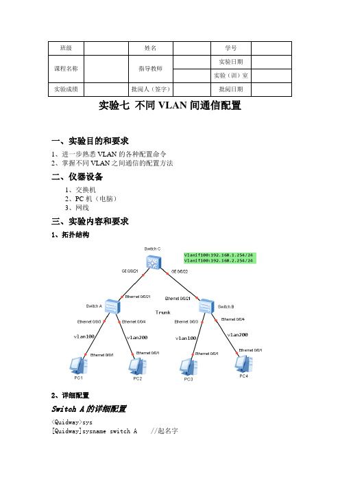
实验七不同VLAN间通信配置一、实验目的和要求1、进一步熟悉VLAN的各种配置命令2、掌握不同VLAN之间通信的配置方法二、仪器设备1、交换机2、PC机(电脑)3、网线三、实验内容和要求1、拓扑结构2、详细配置Switch A的详细配置<Quidway>sys[Quidway]sysname switch A //起名字创建vlan信息[switch A]vlan 100[switch A-vlan100]quit[switch A]vlan 200[switch A-vlan200]quit基于端口划分VLAN[switch A]interface ethernet0/0/3[switch A-Ethernet0/0/3]port link-type access[switch A-Ethernet0/0/3]port default vlan 100[switch A-Ethernet0/0/3]quit[switch A]interface ethernet0/0/4[switch A-Ethernet0/0/4]port link-type access[switch A-Ethernet0/0/4]port default vlan 200[switch A-Ethernet0/0/4]quit配置接口为trunk接口、并允许vlan10、vlan20通过[switch A]interface ethernet0/0/21 进入接口视图[switch A-Ethernet0/0/21]port link-type trunk[switch A-Ethernet0/0/21]port trunk allow-pass vlan 100 200 [switch A-Ethernet0/0/21]quit 退出Switch B的详细配置<Quidway>sys[Quidway]sysname switch B //起名字创建vlan信息[switch B]vlan 100[switch B-vlan100]quit[switchB]vlan 200[switch B-vlan200]quit基于端口划分VLAN[switch A]interface ethernet0/0/3[switch B-Ethernet0/0/3]port link-type access[switch B-Ethernet0/0/3]port default vlan 100[switch B-Ethernet0/0/3]quit[switch B]interface ethernet0/0/4[switch B-Ethernet0/0/4]port link-type access[switch B-Ethernet0/0/4]port default vlan 200[switch B-Ethernet0/0/4]quit[switch A]interface ethernet0/0/21[switch A-Ethernet0/0/21] port link-type trunk[switch A-Ethernet0/0/21] port trunk allow-pass vlan 100 200 [switch A-Ethernet0/0/21]quit 退出Switch C的详细配置<2-57-1>sys[2-57-1]sysname Switch C创建vlan信息[Switch C]vlan 100[Switch C-vlan100]quit[Switch C]vlan 200[Switch C-vlan200]quit配置接口为trunk接口、并允许vlan100、vlan200通过[Switch C]interface GigabitEthernet 0/0/21[Switch C-GigabitEthernet0/0/21]port link-type trunk[Switch C-GigabitEthernet0/0/21]port trunk allow-pass vlan 100 200[Switch C-GigabitEthernet0/0/21]interface GigabitEthernet 0/0/22 [Switch C-GigabitEthernet0/0/22]port link-type trunk[Switch C-GigabitEthernet0/0/22]port trunk allow-pass vlan 100 200 [Switch C-GigabitEthernet0/0/22]quit配置vlan间路由,给对应的vlanif创建IP地址[Switch C]interface vlan 100[Switch C-Vlanif100]ip address 192.168.1.254 24[Switch C-Vlanif100]quit[Switch C]interface vlan 200[Switch C-Vlanif200]ip address 192.168.2.254 24[Switch C-Vlanif200]quit各电脑的IP地址如下3、配置后最后验证:同一个Vlan的电脑互相能ping通不同Vlan的电脑也能ping通四、实验报告要求实验目的,设备,内容(主要是命令),写出每条命令的作用,要求配置过程截图和验证截图。
VLAN间互通两种方式思科配置命令
通过前面的学习,我们已经了解了为了实现局域网广播的隔离,为了更便于网络的管理,我们需要通过VLAN 划分将网络分割成更小的网络。
相同VLAN 之间可以通过级联或TRUNK 来实现通信,不同的VLAN 之间是不能直接通信的,要实现不同VLAN 之间的通信,需要通过三层交换机或路由器。
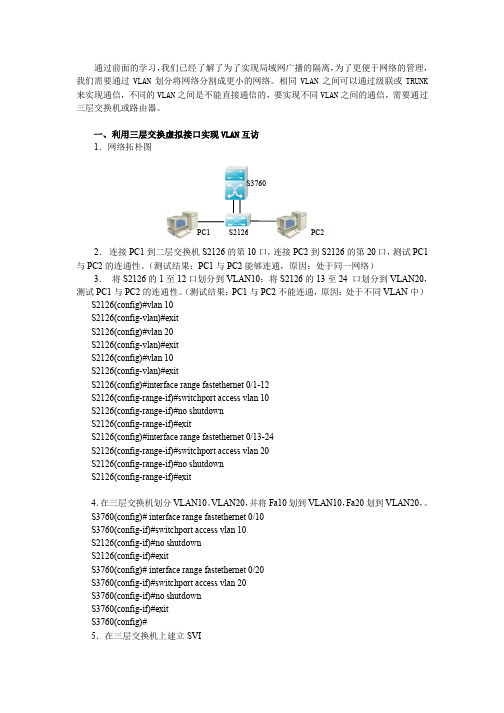
一、利用三层交换虚拟接口实现VLAN 互访1.网络拓朴图2. 连接PC1到二层交换机S2126的第10口,连接PC2到S2126的第20口,测试PC1与PC2的连通性。
(测试结果:PC1与PC2能够连通,原因:处于同一网络)3. 将S2126的1至12口划分到VLAN10;将S2126的13至24 口划分到VLAN20,测试PC1与PC2的连通性。
(测试结果:PC1与PC2不能连通,原因:处于不同VLAN 中)S2126(config)#vlan 10S2126(config-vlan)#exitS2126(config)#vlan 20S2126(config-vlan)#exitS2126(config)#vlan 10S2126(config-vlan)#exitS2126(config)#interface range fastethernet 0/1-12S2126(config-range-if)#switchport access vlan 10S2126(config-range-if)#no shutdownS2126(config-range-if)#exitS2126(config)#interface range fastethernet 0/13-24S2126(config-range-if)#switchport access vlan 20S2126(config-range-if)#no shutdownS2126(config-range-if)#exit4.在三层交换机划分VLAN10、VLAN20,并将Fa10划到VLAN10,Fa20划到VLAN20,。
宽带接入之MAVLAN互通介绍课件

06
方案六:使用云服务 进行互通,可以实现 远程访问和网络优化, 但需要较高的网络带 宽和稳定的网络环境。
05
方案五:使用SDWAN进行互通,可以 实现网络优化和负载 均衡,但需要较高的 网络带宽和稳定的网 络环境。
04
方案四:使用VPN进 行互通,可以实现远 程访问,但需要较高 的网络带宽和稳定的 网络环境。
04
M AV L A N 可 以 提 高 网 络 性 能 , 降 低 网 络 维 护 成 本 , 提 高 网 络 可 靠 性 。
M AV L A N 工 作 原 理
M AV L A N 是 一 种 虚 拟局域网技术,可 以将多个物理端口 划分为一个逻辑网 络。
M AV L A N 通 过 将 多 个物理端口划分为 一个逻辑网络,可 以实现网络资源的 共享和网络管理的 简化。
M AV L A N 支 持 多 种 网络协议,如IP、 IPX等,可以实现 不同协议的网络互 通。
M AV L A N 支 持 多 种 网络拓扑结构,如 星型、总线型等, 可以实现网络拓扑 结构的灵活选择。
M AV L A N 应 用 场 景
企业网络:实现 不同部门之间的
网络隔离和访问 1
控制
酒店网络:实现 4
01
MAVLAN(Multiple Access Virtual Local Area Network)是一种虚拟局域网技术,允许 多个用户共享一个物理网络接口。
02
M AV L A N 通 过 将多 个用 户连 接到 一个 虚拟 局域 网中 ,实 现了 网络 资源 的有 效管 理和 分配 。
03
M AV L A N 支 持 多 种 网 络 协 议 , 如 以 太 网 、 令 牌 环 网 等 , 可 以 满 足 不 同 用 户 的 需 求 。
《VLAN间相互通信》课件

04
协议问题
检查网络设备之间的协议是否正常, 如STP(生成树协议)是否正常工作。
故障排除工具
01
02
03
04
网络测试仪
用于检测网络线路的连通性和 信号质量。
网络分析仪
用于抓取网络数据包,分析网 络协议和流量状况。
网络管理软件
用于监控网络设备的状态和性 能。
命令行接口
用于配置网络设备和查看设备 日志等。
03
基于IP子网的VLAN
基于IP子网的VLAN是根据设备所连 接的IP子网来划分VLAN的,同一 VLAN内的设备具有相同的IP子网。
2023
PART 02
VLAN间通信原理
REPORTING
静态路由
静态路由是指手动配 置的路由信息,需要 在路由器上逐条添加 。
缺点是扩展性差,需 要手动调整,不适合 大规模网络。
2023
REPORTING
《VLAN间相互通信 》PPT课件
2023
目录
• VLAN基础介绍 • VLAN间通信原理 • VLAN间通信配置 • VLAN间通信故障排除 • VLAN间通信应用场景
2023
PART 01
VLAN基础介绍
REPORTING
VLAN定义
VLAN定义
VLAN(Virtual Local Area Network)即虚拟局域网,是一种通过将局域网 内的设备逻辑地而不是物理地划分成一个个网段,从而实现虚拟工作组的技术 。
收集信息
查看网络设备的日志 文件,收集相关网络 配置和状态信息。
分析问题
根据收集到的信息, 分析可能导致故障的 原因。
故障定位
确定故障的具体位置 ,可能是某个设备、 某个端口或某个 VLAN配置错误。
不同VLAN相互通信配置方法教程

不同VLAN相互通信配置方法教程交换机的主要功能包括物理编址、网络拓扑结构、错误校验、帧序列以及流控。
交换机还具备了一些新的功能,如对VLAN(虚拟局域网)的支持、对链路汇聚的支持,甚至有的还具有防火墙的功能。
有时需要两台服务器相互通信,所在还需要在3550上配置VLAN间相互通信,下面一起看看!本实验需求:通过在cisco catalyst 3550来规划VLAN 100 和VLAN 200,并且配置DHCP 让VLAN100人事部计算机获得IP地址为192.168.0.0/24,让VLAN200市场部计算机获得IP地址为172.16.0.0/24。
因为市场部和人事部因为业务上的关系,需要两台服务器相互通信,所在还需要在3550上配置VLAN间相互通信。
实验拓扑:实验过程第一步配置Catalyst 3550基础配置复制代码代码如下:Switch>Switch>enableSwitch#conf tEnter configuration commands, one per line. End with CNTL/Z.Switch(config)#host 35503550(config)#no ip do lo3550(config)#line con 03550(config-line)#no exec-t3550(config-line)#logg syn3550(config-line)#exit第二步在Catalyst 3550 划分VLAN 100和VLAN 200 //进入全局配置模式下,划分VLAN(请问catalyst 3500支持在全局模式下划分VLAN吗?)复制代码代码如下:3550(config)#vlan 100//给VLAN100命名3550(config-vlan)#name renshibo3550(config-vlan)#int f0/133550(config-if)#switchport mode access3550(config-if)#switchport access vlan 1003550(config-if)#spanning-tree portfast//请问什么时候需要在交换机接口下配置portfast?这里如果不配置可以吗?%Warning: portfast should only be enabled on ports connected to a singlehost. Connecting hubs, concentrators, switches, bridges, etc... to thisinterface when portfast is enabled, can cause temporary bridging loops.Use with CAUTION%Portfast has been configured on FastEthernet0/13 but will onlyhave effect when the interface is in a non-trunking mode.3550(config-if)#vlan 2003550(config-vlan)#name shichangbo3550(config-vlan)#int f0/153550(config-if)#sw mo acc3550(config-if)#sw acc vlan 2003550(config-if)#spanning-tree portfast%Warning: portfast should only be enabled on ports connected to a singlehost. Connecting hubs, concentrators, switches, bridges, etc... to thisinterface when portfast is enabled, can cause temporary bridging loops.Use with CAUTION%Portfast has been configured on FastEthernet0/15 but will onlyhave effect when the interface is in a non-trunking mode.//验证VLAN的配置3550#show vlan briefVLAN Name Status Ports---- -------------------------------- --------- -------------------------------1 default active Fa0/1, Fa0/2, Fa0/3, Fa0/4Fa0/5, Fa0/6, Fa0/7, Fa0/8Fa0/9, Fa0/10, Fa0/11, Fa0/12Fa0/14, Fa0/16, Fa0/17, Fa0/18Fa0/23, Gi0/1, Gi0/2100 renshibo active Fa0/13200 shichangbo active Fa0/151002 fddi-default act/unsup1003 token-ring-default act/unsup1004 fddinet-default act/unsup1005 trnet-default act/unsup第三步配置SVI(交换虚拟接口)复制代码代码如下:3550#conf tEnter configuration commands, one per line. End with CNTL/Z.//进入VLAN 100 虚拟接口下3550(config)#int vlan 100//增加接口描述,以便将来排错更加方便3550(config-if)#description Connection to renshibo//这里配置的IP地址就是人事部PC的默认网关地址,如果VLAN 接口不配置IP地址,后面的DHCP配置中,PC能否获得IP地址吗??3550(config-if)#ip add 192.168.0.1 255.255.255.03550(config-if)#no sh3550(config-if)#int vlan 20000:13:22: %LINEPROTO-5-UPDOWN: Line protocol on Interface Vlan200, changed state to up3550(config-if)#description Connection to shichangbo3550(config-if)#ip add 172.16.0.1 255.255.255.03550(config-if)#no sh3550(config-if)#3550#conf t//开启catalyst 3550三层交换路由功能(默认是关闭的)请问cisco catalyst那些型号交换机是三层交换机?3550(config)#ip routing3550(config)#exit3550#sh ip route//两条直连路由条目Codes: C - connected, S - static, R - RIP, M - mobile, B - BGPD - EIGRP, EX - EIGRP external, O - OSPF, IA - OSPF inter areaN1 - OSPF NSSA external type 1, N2 - OSPF NSSA external type 2E1 - OSPF external type 1, E2 - OSPF external type 2, E - EGPi - IS-IS, su - IS-IS summary, L1 - IS-IS level-1, L2 - IS-IS level-2ia - IS-IS inter area, * - candidate default, U - per-user static routeo - ODR, P - periodic downloaded static routeGateway of last resort is not set172.16.0.0/24 is subnetted, 1 subnetsC 172.16.0.0 is directly connected, Vlan200C 192.168.0.0/24 is directly connected, Vlan100Designated bridge has priority 32768, address ccd1.0a80.0000Designated port id is 129.65, designated path cost 0Timers: message age 0, forward delay 0, hold 0Number of transitions to forwarding state: 1BPDU: sent 993, received 92第四步在Catalyst 3550上配置DHCP,以便于VLAN100和VLAN200下客户端获得IP地址,掩码,网关,DNS等复制代码代码如下://全局下打开DHCP服务.默认是开启的吗?那为什么还要需要开启了?3550(config)#service dhcp//关闭dhcp 客户端IP冲突日志记录信息3550(config)#no ip dhcp conflict logging//配置地址池名称,地址池名称为任意字符(这里定义的名字VLAN的名称)3550(config)#ip dhcp pool renshibo//配置PC所获得网段地址范围,和掩码,(这里有几种命令语句格式)(network 192.168.0.0 255.255.255.0)3550(dhcp-config)#network 192.168.0.0 /24//配置网关地址3550(dhcp-config)#default-router 192.168.0.1//配置DNS(域名解析服务器)可选配置请问什么时候PC需要配置DNS地址?局域网通讯需要吗?3550(dhcp-config)#dns 218.30.19.40 61.134.1.4//配置域名3550(dhcp-config)#domain-name //配置地址租期为永久3550(dhcp-config)#lease infinite3550(dhcp-config)#exit//配置排除的IP地址范围,不从地址池内分配的地址,不配置排除地址可以吗?3550(config)#ip dhcp excluded-address 192.168.0.13550(config)#ip dhcp pool shichangbo3550(dhcp-config)#network 172.16.0.0 /243550(dhcp-config)#default-router 172.16.0.13550(dhcp-config)#dns 218.30.19.40 61.134.1.43550(dhcp-config)#domain-name 3550(dhcp-config)#lease infinite3550(dhcp-config)#exit3550(config)#ip dhcp excluded-address 172.16.0.1第五步在市场部PC上验证是否能从catalyst 3550获得IP地址, 如图:开始-运行-cmd-ipconfig /allimage第六步在Catalyst 3550查看PC获得的IP地址是否正确复制代码代码如下://查看DHCP绑定信息3550#sh ip dhcp bindingIP address Client-ID/ (MAC地址) Lease expiration TypeHardware address172.16.0.2 0100.16d3.249f.fd Infinite Automatic192.168.0.2 0100.1641.15e8.5c Infinite Automatic第七步在交换机测试是否可以ping通市场部和人事部PC复制代码代码如下:3550(config)#exit3550#00:26:41: %SYS-5-CONFIG_I: Configured from console by console3550#ping 172.16.0.2Type escape sequence to abort.Sending 5, 100-byte ICMP Echos to 172.16.0.2, timeout is 2 seconds:Success rate is 100 percent (5/5), round-trip min/avg/max = 1/2/4 ms3550#ping 192.168.0.2Type escape sequence to abort.Sending 5, 100-byte ICMP Echos to 192.168.0.2, timeout is 2 seconds:Success rate is 100 percent (5/5), round-trip min/avg/max = 1/1/4 ms第八步在市场部PC上用ping命令测试是否可以ping通VLAN100(人事部) 下PC 如图:测试结果如下,可以ping通,实验现象成功!补充:交换机常见故障解决通过观察初步定为故障,一般如果设备正常,而且线路连接也正常,则交换机指示灯会亮绿色并且一闪一闪的。
实验10-三层交换机实现不同vlan间通信

验证测试:验证 F0/24 端口已被设为 tag vlan 模式
SwitchA#show interfaces fastEthernet 0/24 switchport
Interface Switchport Mode
Access Native Protected VLAN lists
---------- ---------- --------- ------- -------- --------- -------
name sales ! vlan 20
name technical ! interface FastEthernet 0/5
switchport access vlan 10 ! interface FastEthernet 0/15
switchport access vlan 20 ! interface FastEthernet 0/24
Fa0/24 Enabled Trunk 1
1
Disabled All
步骤 5.验证 PC0 与 PC2 能相互通信,但 PC0 和 PC1 不能相互通信。 C:\Documents and Settings\Administrator>ping 192.168.10.30
!在 PC1 的命令行方式下能 ping 通 PC3 Pinging 192.168.10.30 with 32 bytes of data:
Broadcast address : 255.255.255.255
PhysAddress
: 00d0.f8b8.289c
Interface
: VL20
Description
: Vlan 20
OperStatus
不同VLAN之间的相互通信
interface FastEthernet 0/14
switchport access vlan 20
!
interface FastEthernet 0/15
switchport access vlan 20
!
endБайду номын сангаас
s35-1#
s35-1#
1909-15-19 03:08:53 @5-LINKUPDOWN:Fa0/1 changed state to up
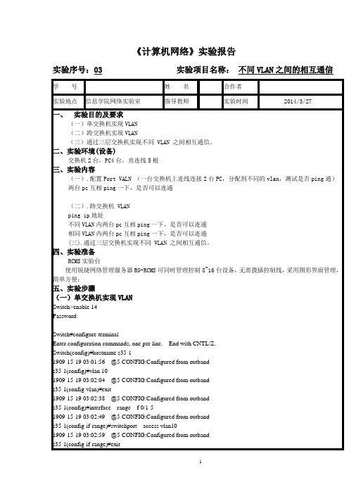
《计算机网络》实验报告
实验序号:03实验项目名称:不同VLAN之间的相互通信
学 号
姓名
合作者
实验地点
信息学院网络实验室
指导教师
实验时间
2014/3/27
一、实验目的及要求
(一)单交换机实现VLAN
(二)跨交换机实现VLAN
(三)通过三层交换机实现不同VLAN之间相互通信。
二、实验环境(设备)
交换机2台,PC4台,直连线5根
Fa0/20,Fa0/21,Fa0/22
Fa0/23,Fa0/24
10 VLAN0010 active Fa0/1 ,Fa0/2 ,Fa0/3
Fa0/4 ,Fa0/5 ,Fa0/9
20 VLAN0020 active Fa0/9 ,Fa0/11,Fa0/12
Fa0/13,Fa0/14,Fa0/15
s2126-2#show run
!
interface FastEthernet 0/11
switchport access vlan 20
!
interface FastEthernet 0/12
switchport access vlan 20
不同vlan之間相互ping通實踐命令(單臂路由協議)

不同vlan之間相互通信(單臂路由)路由器的配置Router>enRouter#conf tEnter configuration commands, one per line. End with CNTL/Z.Router(config)#inRouter(config)#interface fRouter(config)#interface fastEthernet 0/0Router(config-if)#no shuRouter(config-if)#no shutdown%LINK-5-CHANGED: Interface FastEthernet0/0, changed state to up%LINEPROTO-5-UPDOWN: Line protocol on Interface FastEthernet0/0, changed state to upRouter(config-if)#exitRouter(config)#Router(config)#Router(config)#Router(config)#inRouter(config)#interface fRouter(config)#interface fastEthernet 0/0.1%LINK-5-CHANGED: Interface FastEthernet0/0.1, changed state to up%LINEPROTO-5-UPDOWN: Line protocol on Interface FastEthernet0/0.1, changed state to upRouter(config-subif)#Router(config-subif)#Router(config-subif)#Router(config-subif)#Router(config-subif)#enRouter(config-subif)#encapsulation doRouter(config-subif)#encapsulation dot1Q 10Router(config-subif)#ip addRouter(config-subif)#ip address 192.168.1.1 255.255.255.0Router(config-subif)#no shuRouter(config-subif)#no shutdownRouter(config-subif)#exitRouter(config)#inRouter(config)#interface fRouter(config)#interface fastEthernet 0/0.2%LINK-5-CHANGED: Interface FastEthernet0/0.2, changed state to up%LINEPROTO-5-UPDOWN: Line protocol on Interface FastEthernet0/0.2, changed state to upRouter(config-subif)#Router(config-subif)#enRouter(config-subif)#encapsulation aoRouter(config-subif)#encapsulationdoRouter(config-subif)#encapsulation doRouter(config-subif)#encapsulation dot1Q 20Router(config-subif)#ip addRouter(config-subif)#ip address 192.168.2.1 255.255.255.0Router(config-subif)#no shuRouter(config-subif)#no shutdownRouter(config-subif)#exitRouter(config)#Router(config)#Router(config)#Router(config)#Router(config)#Router(config)#Router(config)#Router(config)#exitRouter#%SYS-5-CONFIG_I: Configured from console by consoleRouter#Router#Router#Router#Router#Router#shoRouter#show ip rouRouter#show ip routeCodes: C - connected, S - static, I - IGRP, R - RIP, M - mobile, B - BGPD - EIGRP, EX - EIGRP external, O - OSPF, IA - OSPF inter areaN1 - OSPF NSSA external type 1, N2 - OSPF NSSA external type 2E1 - OSPF external type 1, E2 - OSPF external type 2, E - EGPi - IS-IS, L1 - IS-IS level-1, L2 - IS-IS level-2, ia - IS-IS inter area* - candidate default, U - per-user static route, o - ODRP - periodic downloaded static routeGateway of last resort is not setC 192.168.1.0/24 is directly connected, FastEthernet0/0.1C 192.168.2.0/24 is directly connected, FastEthernet0/0.2Router#conf tEnter configuration commands, one per line. End with CNTL/Z.Router(config)#ip dhjRouter(config)#ip dhRouter(config)#ip dhcp poRouter(config)#ip dhcp pool 1Router(dhcp-config)#netRouter(dhcp-config)#network 192.168.1.0 255.255.255.0 Router(dhcp-config)#deRouter(dhcp-config)#default-router 192.168.1.1 Router(dhcp-config)#dnRouter(dhcp-config)#dns-server 1.1.1.1Router(dhcp-config)#exitRouter(config)#ip dhcpRouter(config)#ip dhcp pRouter(config)#ip dhcp poolRouter(config)#ip dhcp pool 2Router(dhcp-config)#netRouter(dhcp-config)#network 192.168.2.0 255.255.255.0 Router(dhcp-config)#dnRouter(dhcp-config)#deRouter(dhcp-config)#default-router 192.168.2.1 Router(dhcp-config)#dnRouter(dhcp-config)#dns-server 1.1.1.1Router(dhcp-config)#exit交換機的配置Switch>enSwitch#conf tEnter configuration commands, one per line. End with CNTL/Z. Switch(config)#vlSwitch(config)#vlan 10Switch(config-vlan)#exitSwitch(config)#vlSwitch(config)#vlan 20Switch(config-vlan)#exitSwitch(config)#Switch(config)#Switch(config)#infSwitch(config)#intSwitch(config)#interface fSwitch(config)#interface fastEthernet 0/2Switch(config-if)#swSwitch(config-if)#switchport moSwitch(config-if)#switchport mode accSwitch(config-if)#switchport mode accessSwitch(config-if)#swSwitch(config-if)#switchport accSwitch(config-if)#switchport access vlSwitch(config-if)#switchport access vlan 10Switch(config-if)#exitSwitch(config)#inSwitch(config)#interface fSwitch(config)#interface fastEthernet 0/3Switch(config-if)#swSwitch(config-if)#switchport moSwitch(config-if)#switchport mode accSwitch(config-if)#switchport mode accessSwitch(config-if)#swSwitch(config-if)#switchport accSwitch(config-if)#switchport access vl Switch(config-if)#switchport access vlan 20 Switch(config-if)#exitSwitch(config)#Switch(config)#Switch(config)#Switch(config)#Switch(config)#inSwitch(config)#interface fSwitch(config)#interface fastEthernet 0/1 Switch(config-if)#swSwitch(config-if)#switchport moSwitch(config-if)#switchport mode tr Switch(config-if)#switchport mode trunk Switch(config-if)#exit。
