Proceedings of the 29th Annual Hawaii International Conference on System Sciences- 1996 Whe
ASDD Technology in Deepwater Drilling and Its Process of Commercialization
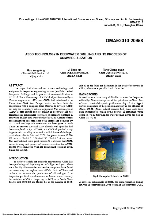
Proceedings of the ASME 2010 29th International Conference on Ocean, Offshore and Arctic EngineeringOMAE2010June 6-11, 2010, Shanghai, ChinaOMAE2010-20958 ASDD TECHNOLOGY IN DEEPWATER DRILLING AND ITS PROCESS OFCOMMERCIALIZATIONGuo Yong-feng China Oilfield Services Ltd., Beijing, ChinaJi Shao-junChina Oilfield Services Ltd.,Beijing, ChinaTang Chang-quanChina Oilfield Services Ltd.,Beijing, ChinaABSTRACTThe paper had discussed on a new technology and equipment in deepwater engineering, ASDD (Artificial Seabed Deepwater Drilling), and its process of commercialization in COSL of China. The concept of ASDD had put forwarded by a Norway engineer in 1993, and COSL had introduced it to China since 2004 from Europe, which has been built the cooperation with a company from Norway to develop ASDD not only the technology but also equipment. The advantages of ASDD is both reduce cost of drilling in deepwater and use common semi submersible to replace of expensive platform in deepwater drilling until water depth of 1500 m. A series of tests and simulations had been done both abroad and domestic by COSL and two large trial operations had been gone in South China Sea between 2008 and 2009. The trial well operation had been completed in Apr. of 2009, and COSL dispatched many huge vessels, including to Nanhai V, which is one of the hugest semi submersible in Aria, and AHVs that power is over 10,000 HP, such as Nanhai 212, Nanhai 213, Nanhai 216 and so on. The trial well had taken great success. It is obvious that COSL intend to carry out process of commercialization for ASDD, and the two commercial wells had been planed to drill in South China Sea in 2010.INTRODUCTIONIn order to satisfy the domestic consumption, China has been producing and importing lots of oil/gas each year. There are a few big oil companies and service companies have found out more ways to explore new oilfields both offshore and onshore, to increase the production of oil and gas [1]. A deepwater gas field was discovered in Liwan, where is nearly the mainland of China, deeper up to 1470 m in South China Sea by both CNOOC and Husky Co. in the summer of 2006. Big oil or gas fields are discovered in the areas of deepwater in China, where are especially South China Sea. BACKGROUNDIt needs to overcome many difficulties to enter the deepwater oilfield by Chinese enterprises of the petroleum in China. One of them is short of deepwater platforms or ships. As the biggest service companies of the petroleum industry in the offshore of China, COSL (China oilfield services Ltd.) have only three semi submersibles which could operate in maximum water depth of 475 m. However, the water depth in Liwan gas field in China is 1470 m.Fig.1 Concept of Atlantis or ASDDA new semi submersible of COSL, the sixth generation drillingrig, was in construction in 2006 to drill in the deepwater. COSLselected two ways to step to deepwater [2]. One is to build a deepwater semi submersible in cooperation with other company; the other is to upgrading or modifying some equipment for installing on existing semi submersibles to become the deepwater drilling rigs. It needs long time for fabricating the vessel for deepwater drilling, approximate 4-5 years, so COSL plans to adopt proper facility to improve existing semi submersibles for drilling in deepwater. The improved semi submersibles will drill in deepwater before new deepwater vessels start in operating [3].It is obvious that the cost of improved semi submersibles would be lower than that of an ordinary deepwater vessel. In fact, it is estimated that new fabricating semi-submersible will drill in water depth ranging from 1,500m to 3,000m and the improved semi submersibles will operate in shallower water of 1,500m.CONCEPT OF ASDD FOR DEEPWATER DRILLINGIt may be explained in simple words on Atlantis concept, also called ASDD (Artificial Seabed Deepwater Drilling), or called ABS (Artificial Buoyancy Seabed) concept, which was put forwards by the expert from Norway, to drill in deepwater. The concept of Atlantis was invented by a Norwegian in 1993, and the main principle is to form an artificial seabed by a buoyancy module between the under section of semi-submersible and mud line. The upper section of the buoyancy module connects to the risers and lower section of the buoyancy module willconnect to seafloor or the mud line through some special casings, called tie pipes in general. The convention BOP (Blow out Preventer), rather than sub-sea BOP, is installed at top ofFig. 2 Illustration of ASDD systemthe buoyancy. The method of ASDD provides the up force by the buoyancy unit, where is 200 to 400 m below the sea surface, which hanga tieback 22-in casing string from the wellhead in the seabed asan anchoring system [4]. This means that the BOP and riser donot have to be run to the seabed in deepwater. Less expensiverigs can carry out the drilling, anchored by taut-leg polyester moorings, and sub sea equipment will not be subjected to verylow temperatures with associated flow assurance problems. Installation of the buoy can be achieved by standard anchor handlers, avoiding the need for heavy lift vessels [5]. The profileof the system is shown in Fig. 2.RESEARCH TO PROVEN ON FEASIBILITY OF ASDDIn order to proven on feasibility of concept of Atlantis or ASDD, the engineers from COSL started to design and executea series of simulations in the universities and institutes, in the same time, a few the model tests in pools of labs, which mostof them had been carried out in China.There were 8 tests being designed and carried out. Some of them were designed to prove the feasibility of the facility, and others to prove the performances of the facility [6]. The contentsof tests to prove feasibility of the facility are showed in the Table 1.A series of feasibility reports about this concept were based onthe summary of the tests. And several seminars or workshops were held in the cities of China to discuss the concept. It is concluded that the ASDD can be a replacement of the deepwater drilling vessel to operate in area of depth ranging from 500 m to 1500m[7]. COSL will carry out more tests before upgrading the facility of ASDD and starting the trial well forthis concept.TESTS TO SIMULATE PERFORMANCE OF ASDDAfter completing the feasibility report, COSL arranged a lot of Table 1 Research to Proven on Feasibility of ASDDNo.Time Places Method PurposeofTest1 August,2004ShanghaiJiaotongUniversitySimulating bySeaConstructionsoftware ofcomputerInstructionStrength2 August,2004ShanghaiJiaotongUniversityModel test inpool of 5 mdepthInstructionStrength andstability3 March, 2005HarbinEngineeringUniversitySimulating byFEM softwareof computerStatic responsebetween drillsemi-submersibleand the facility4 March, 2005Xi’anJiaotongUniversitySimulating byFEM softwareof computerDynamic responsebetween drillsemi-submersibleand the facilitytests again as presented in Table 2. Meantime, a test about the mechanic properties of facility was conducted by ADTH in Marintek Ocean Laboratory, Trondheim, Norway [8].The purpose of the tests is to acquire some data about properties of the facility, including mechanics of not only staticbut also dynamic, hydraulic, and environmental and so on. The tests show that data shall be obtained about the maximum resistant force under the current impact, the maximum offset of the facility during bad weather, the maximum lift force when buoyancy is vacuumed, and the maximum bend when current impacting become biggest.Table 2Tests to Simulate Performance of ASDDTRIAL OF MODEL IN LAKETo prove both feasibility and properties of the facility, COSL designed and executed a large experiment in the lake of 140 m depth in Kunming , China.The test in Kunming is a large scale experiment for deepwater drilling, took almost one month. The test not only used 10 tons of steel to build the model and modify the vessel but also installed 4 sets of monitor instrument. The key stage lasted 2 days to perform the load testing of the facility in the lake. The model in this test consists of the pipe of 6 inches with length of 150 m.It is not only important but also necessary to carry out a large-scale model test before drilling a test well. The principle of the test is to use the analogy method in mathematics to design a series of models, in the lake of 140 m depth to simulate drilling procedure in the deepwater. Fig. 3 shows the situation of the test of deepwater drilling in a lake of Kunming, ChinaNot only geometry similarity but also physical similarities are applied to the tests. In the geometry analogy, the engineers were ruling a factor, 1:10, meaning the radio between the model and the prototype [9]. The pipe would be simulating to the casing of 20 inches in deepwater environment. There are 27 inspecting points by the sensors of both stress and strain, from above of water to under water, until the bed of the lake.Fig. 3 Situation of the test of deepwater drilling in a lake ofKunming, ChinaCONDUCT BOTH PRE-TRIAL AND TRIAL WELL IN SOUTH CHINA SEAThere are two activities of engineering executed by COSL at the same place of South China Sea, which is both pre-trial on June 1st to 9th of 2008, and the trial well on March 25th to April 24th of 2009.The location both sites of operation belong to South China Sea, and its coordinates 18.685 N, 112.478 E (18 42 N, 112 26 30.12”E), Water Depth of 476m1. Operation of Pre-trial in 2008The operation of Pre-trial had been carried out on May 29th to June 7th, 2008, where is located the eastern of Hainan island of 250 km. There were 3 AHVs took part in the operation.This document provides an overview of requirements and procedures for a preliminary offshore trial of the Atlantis Unit. The main aims of pre-trial operation is to not only verify the feasibility of installing program on the buoyancy by AHV’s but also assess vessels capability, and develop the particular ship handling skills required for deployment, station keeping and recovery of the buoyancy of ASDD, thereby reducing the risk of accidental events during the actual trial well[10].Others, another aim of pre-trial operation is involved to test on function test and calibrated the umbilical, control systems and ROV facilities, with the intention of further reducing the buoyancy exposure to risk, during the actual trial well. To Fig.4.No. Time Places Method PurposeofTest1 March, 2005 Shanghai708ShippingInstituteReview tohistory casingand Simulatingof softwareRiskanalysis offor facility inoperation2 March, 2005 BeijingMarineInstituteMotion Analysisby historycasing andsimulation ofsoftwareMotionAnalysis3 March, 2005 QingdaoOceanEnvironment InstituteReview tohistory casingand Simulatingof softwarePredictingthe effect ofenvironmentto thefacility4 March, 2005 ShanghaiJiaotongUniversityFEM SimulatingfurtherAnalysis ofMechanicsin details5 April,2005MarintekLab ofNorwaymodel test inpool of 10mdepthDisconnectin case ofemergency6 April,2005KunmingcityBig model testin the lake of140 m depthSimulatingoperation indeepwaterSome progresses had been executed in the pre-trial operation inJune of 2008, such as drawing the buoyancy in long distance;to install the weight chains; to test the sunk of buoyancy; to testthe stability of buoyancy under 250 m of surface of the sea; totest of shift of buoyancy by both AHVs; to running ROV whenthe buoyancy sinking; to carry out the buoyancy float testingand so on;2. Operation of Trial Well in 2009Fig.5 Situation of Trail well by Nanhai 5 rig in SouthChina SeaThe trial well operation had been carried out by COSL in SouthChina Sea, where is located in 250 km of eastern on Hainanisland of China, on March 25th to April 24th of 2009 [11].During operation of the trial well, COSL dispatched many hugevessels, including to Nanhai V, which is one of the hugest semisubmersible in Aria, and AHVs that power is over 10,000 HP,such as Nanhai 212, Nanhai 213, Nanhai 216 and so on. Fig.5Situation of Trail well by Nanhai 5 rig in South China Sea.Thetrial well had taken great success. It is obvious that COSLintend to carry out process of commercialization for ASDD,and the two commercial wells had been planed to drill in SouthChina Sea in 2010. Fig.6.Fig.6 Situation of installing Buoyancy in Trial wellCONCLUSIONSThe conclusions had been made through the operation of thetrial well by COSL in South China Sea as below.The trial well operation had been arrived at goals that madebefore began of the trial well, and it had been succeeded inengineering of deepwater in primary [12].The trial well operationhad done some working to use the buoyancy to as an assistantdevice of deepwater drilling in the world, and it achievedresults that estimate by COSL.The trial well had conducted by some special methods andmeasures, such as cementing liquid and progresses, in additionto logging arts, to solve some problems that happen in situationof ASDD operation; in other words, engineers from COSL hadsolved a series of problems that is only happen in condition ofASDDD operation.REFERENCES[1] Frank Lim, Guo Yongfeng. Ji Shaojun .Xu Liangbin Near-surface BOP Drilling System 2008-EF-003[2] C.S. Avelar, O.L.A. Santos, P.R. Ribeiro. Well ControlAspects Regarding Slender Well Drilling With Surface andSubsea BOP, 94852-MS, 2005.[3]A. Simondin, D. MacPherson, N. Touboul, G. Ragnes: TotalA Deepwater Well Construction Alternative: Surface BOPDrilling Concept using Environmental Safe Guard IADC/SPE87108.[4]Guo Yongfeng, Ji Shaojun, Ye Aijie. New Device forDrilling in Deepwater Under Semi submersible: ABS unit.SPE-101349, 2006.[5] A.S Westlake, MCS; K. Uppu, MCS Ebabling Solutions For Deepwater Drilling Riser Management-A Critical Evaluation OTC18646.[6] Chau Nguyen, Ricky Thethi, and Frank Lim Storm-Safe Deepwater Drilling IADC/SPE 103338 .[7] E.Kogure, M.Ohashi, S.Urabe, A Tanabe Applications of a near surface disconnect able drilling riser in deepwater IADC/SPE 47828.[8]G Brander, E Magne, T Newman, T Taklo C Mitchill, Drilling in Brazil in 2887m Water depth using a Surface BOP system and a DP Vessel DOT&IADC 2003.[9] Yongfeng Guo, Shaojun Ji, Changquan Tang. Feasibility of Deepwater Drilling in South China Sea by Applying ABS unit. The International Society of Offshore and PolarEngineers(ISOPE) Lisbon, Portugal, 2007.[10] E.R. Balch, MCS; W.K. Kavanagh, MCS; P.E. Griffin;L.E. Chouinard, H.M. Thompson, ChevronTexaco. Running Fairings For Deepwater Drilling In The Gulf Of Mexico –A Cost-Benefit Approach To Deciding The Faired Length .OTC 15286.[11]Nicolas Touboul, Lee Womble, John Kotrla, et al. New Technologies Combine to Reduce Drilling Costs in Ultra deepwater Applications, 90830-MS, 2004.[12] Guo Yongfeng, Ji Shaojun, Ye Aijie. Predicting Performances of Device of Deepwater Drilling by Both Testing in Pool and Simulating by Computer, 4th PetroMin Deepwater and Subsea Technology Conference and Exhibition, Hotel Istana Kuala Lumpur, Malaysia, 2006.。
SeatPlan

THE 29TH LEGISLATURE FIRST SESSION
June15, 2015
Free Guided Tours
Led by knowledgeable heritage interpreters, tours begin inside the Legislature Building and run daily. May 1 to September 30 Monday to Sunday: 9 a.m. to 5 p.m. Tours occur every hour. Last tour begins at 4 p.m. October 1 to April 30 Monday to Friday: 9 a.m. to 5 p.m. Saturday, Sunday, and holidays: noon to 5 p.m. Tours occur every hour. Last tour begins at 4 p.m. Tours NOT available on Christmas Day, New Year’s Day and Good Friday. For information on educational programs or to book a tour for a group of 12 or m62. If you are calling from outside Edmonton, dial the toll-free line at 310.0000 and enter the 10-digit number.
Please direct questions about the Legislative Assembly to: Communications Services 801 Legislature Annex Edmonton, Alberta T5K 1E4 laocommunications@assembly.ab.ca Visit our website at assembly.ab.ca for information about the Legislative Assembly. Check out our searchable databases for Hansard and Bills and amendments.
临这会心的语充务擎可左态开和
IPSEC6.EXE ......(Ipv6 安全配置工具). 用于配置 IPv6 安全性的工具.ipsecsnp.dll ....Internet 协议安全策略管理ipsecsvc.dll ....Windows IPSec SPD Server DLLipsmsnap.dll ....IP 安全监视快照IPV6.EXE ........( Ipv6 安全配置工具). 用于安装和配置 IPv6 的工具.ipv6mon.dll .....IF 监视 DLLipxmontr.dll ....IPX 路由监视 DLLipxpromn.dll ....IPX 路由监视 DLLipxrip.dll ......IPX RIPIPXROUTE.EXE ....(IPX 路由). 用于显示和控制 IPX 路由的工具.ipxrtmgr.dll ....IPX 路由管理程序ipxsap.dll ......SAP Agent DLLipxwan.dll ......IPXWANmprddm.dll ......查询拨号管理程序超级用户mprdim.dll ......动态接口管理程序mprmsg.dll ......多协议路由服务消息DLLmprui.dll .......多个提供程序NETSH.EXE .......(路由和远程访问服务配置工具). 用于配置 RRAS 设置.PING6.EXE .......(Ipv6 的Ping 命令). 用于验证指定IP 地址或主机名的连接情况的工具.ROUTEMON.EXE ....(路由控制台监视器).不再受支持的工具. 建议使用netsh 命令.rtm.dll .........路由表管理程序TRACERT6.EXE ....(Ipv6 路由跟踪工具). 用于追踪数据包传输路径的工具. winipsec.dll ....Windows IPSec SPD Client DLLwship6.dll ......IPv6 助手 DLL从 C:\WINDOWS\system32\drivers 中删除以下文件:ipfltdrv.sys ....IP 筛选驱动ipinip.sys ......IP in IP 封装驱动ipnat.sys .......IP 网络地址转换驱动469. The detective detected that the arch was under the marching Arctic architects' protection. 侦探发现,这个拱门是在正在行军中的北极的建筑师保护之下的。
计算机网络服务质量优化方法研究综述

计算机网络服务质量优化方法研究综述作者:王乔平王波王娜娜来源:《科技与企业》2013年第01期【摘要】基于优化方法的机制设计与性能评价成为了当前网络服务质量领域中的一个前沿研究领域。
本文简述了在网络上实现服务质量的现状和解决方案,分析和总结了服务质量保证的关键技术的原理和特点,最后展望了网络服务质量技术的发展。
【关键词】服务质量;性能;综述一、引言随着通信技术和Internet的快速发展,网络会议、视频点播、远程教学、资源下载等大量实时服务在网络上被广泛应用,需要占用大量网络带宽,而且不同业务流对Qos有着不同的要求,这都迫切要求网络传输能提供服务质量保证。
因此,如何保障网络的服务质量是一个重要的研究领域。
(一)QoS定义QoS是指IP的服务质量,也是指IP数据流通过网络时的性能。
它的目的就是向用户提供端到端的服务质量保证。
它有一套度量指标,包括业务可用性、延迟、可变延迟、吞吐量和丢包率等。
简单地说,QoS能够对数据包进行合理的排队,对含有内容标识的数据包进行优化,并对其中特定的数据包赋以较高的优先级,从而加速传输的进程,并实现实时交互。
QoS在可预测、可测量性方面比传统IP有了很大的提高.基本解决了多媒体类应用或者大数据有线传输的需求,并且可提高带宽的使用率。
(二)Qos的主要性能参数实际上,Qos问题主要是由网络对业务性能要求的支持能力不足引起的。
QoS保证就是通过对网络资源进行合理安排,确保网络满足各项业务的要求,目的是为各种业务流(如数据、图像、多媒体等)提供可靠的端到端Qos保证。
用来保证Qos的性能参数包括:①可用性,指用户到IP业务之间连接的可靠性;②延迟,指IP包从网络入口点到达出口点所需的传输时间间隔;③延迟抖动,指在同一条路径上发送的一组数据流中数据包之间的时间差异;④丢包率,指IP包在网络节点之间传输时丢失的IP包数与己发送的IP包总数的比值;⑤吞吐量,指网络中IP包的传输速率。
ASTM B854-98(2004)测量电接触点间歇性的标准导则
Designation:B854–98(Reapproved2004)Standard Guide forMeasuring Electrical Contact Intermittences1This standard is issued under thefixed designation B854;the number immediately following the designation indicates the year of original adoption or,in the case of revision,the year of last revision.A number in parentheses indicates the year of last reapproval.A superscript epsilon(e)indicates an editorial change since the last revision or reapproval.1.Scope1.1The techniques described in this guide apply to electri-cal circuits that include one or more electrical contacts in devices such as slip rings,separable connectors,electrome-chanical relays or closed switch contacts.The user should determine applicability for other devicesTable1.1.2The range of techniques described apply to circuit discontinuities(intermittences)of durations ranging from ap-proximately10nanoseconds to several seconds and of suffi-cient magnitude to cause alteration of the circuit function. Extension of the guide to shorter duration events may be possible with suitable instrumentation.Events of longer dura-tion may be monitored by techniques for dc measurements such as those described in Test Methods B539or by adaptation of methods described in this guide.1.3The techniques described in this guide apply to electri-cal circuits carrying currents typical of signal circuits.Such currents are generally less than100ma.Extension of these techniques to circuits carrying larger currents may be possible, but the user should evaluate applicabilityfirst.1.4This standard does not purport to address all of the safety concerns,if any,associated with its use.It is the responsibility of the user of this standard to become familiar with all hazards including those identified in the appropriate Material Safety Data Sheet for this product/material as pro-vided by the manufacturer,to establish appropriate safety and health practices,and determine the applicability of regulatory limitations prior to use.2.Referenced Documents2.1ASTM Standards:2B539Test Methods for Measuring Resistance of Electrical Connections(Static Contacts)B542Terminology Relating to Electrical Contacts and Their UseB615Practice for Measuring Electrical Contact Noise in Sliding Electrical ContactsB878Test Method for Nanosecond Event Detection for Electrical Contacts and Connectors2.2Other Documents:IEC Publication512,Test2e Contact Disturbance3EIA-364-46Continuity Test Procedure for Electrical Connectors43.Terminology3.1Terms relevant to this guide are defined in Terminology B542except as noted in the following section.3.2Definitions of Terms Specific to This Standard:3.2.1intermittence—a transient increase in the voltage drop across a pair of electrical contacts.4.Significance and Use4.1This guide suggests techniques to evaluate intermit-tences in a contact pair while it is subjected to simulated or actual environmental stress.Such measurements are a valuable tool in predicting circuit performance under these stress conditions and in diagnosing observed problems in circuit function under such conditions.4.2This document is intended to provide some general guidance on the best available practices for detecting,quanti-fying,characterizing and reporting short duration intermit-tences in circuits containing electrical contacts.Certain envi-ronmental stresses such as mechanical shock,vibration or temperature change may cause intermittences.These measure-ment procedures include methods applicable to contacts oper-ating under various conditions in testing or in service.4.3Practice B615defines methods for measuring electrical contact noise in sliding electrical contacts.In contrast Guide B854provides guidance to the various methods for measuring similar phenomena in static contacts.5.Apparatus5.1General Comments—The apparatus required varies de-pending upon the technique selected and the parameters(such as duration and magnitude)of the intermittence that the user1This guide is under the jurisdiction of ASTM Committee B02on Nonferrous Metals and Alloys and is the direct responsibility of Subcommittee B02.11on Electrical Contact Test Methods.Current edition approved May1,2004.Published May2004.Originally approved st previous edition approved in1998as B854–98.2For referenced ASTM standards,visit the ASTM website,,or contact ASTM Customer Service at service@.For Annual Book of ASTM Standards volume information,refer to the standard’s Document Summary page on the ASTM website.3Available from American National Standards Institute(ANSI),25W.43rd St., 4th Floor,New York,NY10036.4Available from Electronic Industries Association,2001Pennsylvania Ave NW, Washington D.C.20006.1Copyright©ASTM International,100Barr Harbor Drive,PO Box C700,West Conshohocken,PA19428-2959,United States.wants to detect.In general,the cabling must be capable of carrying signals of the speed to be detected in the study,and must be isolated from sources of noise that may cause false indications.5.2Special Precautions for Measurements Involving Events Less than 1Microsecond in Duration —Detection of events of duration less than 1microsecond will require special attention to the wiring of the detection circuits and instrumentation.Such attention may include using coaxial cable,shielding the apparatus from interferences and minimizing cable lengths.5.3Specific Apparatus —The apparatus required will vary depending upon the measurement method selected and the environmental stresses imposed during the test.6.Procedure6.1General Comments —The following sections describe,in general terms,several methods that have been used to detect or measure contact intermittences.The user should select an appropriate method and adapt it as required.Table 1presents a comparison of the attributes of the various methods.The following list covers questions that the user should answer before selecting a test method.6.1.1What is the definition of an intermittence in the intended application?For example,what resistance change over what time interval constitutes an intermittence,or what error occurs if the contact resistance changes,or what other definition is appropriate for the intended purpose of the test results?6.1.2Is it necessary to monitor more than one contact simultaneously?If so,is it acceptable to connect the contacts in series?If contacts cannot be connected in series,how many contacts must be measured simultaneously?6.2Test results should be reported in a format appropriate for the application and consistent with the format supplied by the test instrument.6.3Oscilloscope —In this method,an oscilloscope is wired to monitor the potential across the contact(s)of interest while a signal is passed through the contacts.Standards such as IEC Publication 512,Test 2e or EIA 364-46are often implemented using this method.Practice B 615provides a specific circuitthat uses this method.Examples of the use of this method are shown in the reference by Currence and Rhoades.56.3.1Fig.1shows a schematic representation of anexample of how this method may be implemented.In selecting an oscilloscope,choose a model with response time fast enough to observe events of the duration of interest in the study.The user may find it convenient to use an oscilloscope capable of storing and printing results.6.4Custom Circuitry —In this method,the user assembles circuitry to measure the effects of the intermittences under the conditions of interest.For example,the circuitry may simulate the type of source and detector circuitry that the user plans to design into a system.Alternatively,the user may design circuitry based on specialized components to achieve capabili-ties different from those found in commercial instruments.An example of custom circuitry was described by Abbott and Schreiber.66.4.1Fig.2shows a schematic representation of an example of how this method may be implemented.The source and detector incorporate the specific devices,technology,driver5Currence,R.and Rhoades,W.,“Predicting,Modeling and Measuring Transient Resistance Changes of Degraded Electrical Contacts,”Electrical Contacts,Proceed-ings of the 29th Meeting of the Holm Conference on Electrical Contacts,Illinois Institute of Technology,p.81,1983.6Abbott,W.H.and Schreiber,K.L.,“Dynamic Contact Resistance of Gold,Tin and Palladium Connector Interfaces During Low Amplitude Motion,”Proceedings of Holm Conference,1981,p.211.TABLE 1Comparison of Methods of Monitoring Electrical Contact IntermittencesMethodTypical Number of Channels Typical Event CharacterizationPossible AdvantagesOscilloscope 1,2or 4D V vs timedetailed characterization of each eventCustom Circuitry1per circuitPresence or absence of one or more events during a preselected monitoring interval,such events defined as above a preselected threshold of D R and duration,the number of events during the interval may or may not be recorded.Ability to closely model actual circuit conditions,allows use of various technologies in the transmitting and receiving devicesEvent Detector 1to 64Presence or absence of one or more events during a preselected monitoring interval,such events defined as above a preselected threshold of D R and duration,but the number of events during the interval is not recorded.Multichannel capability,selection of thresholds for events to be countedBit Error Rate 1ratio of errors to number of bits transmittedThe format of the results is readily applicable to ranking of interconnectiondevices with respect to transmission quality for aspecific signal formatFIG.1Schematic Representation of Oscilloscope Methodcircuits,amplifiers,etc.,that are of interest in the intended application of the connection or switch under test.The control and monitoring instrumentation monitors the performance of the connecting circuit by a suitable method such as comparing the signal received against a standard.6.5Commercial Event Detector —In this method,a com-mercial instrument that detects high resistance events is wired to monitor one or more electrical contacts under evaluation.Test Method B 878gives detailed instructions for implement-ing a specific version of this method.Certain instruments allow monitoring of several electrical contacts independently and simultaneously.Typically,the instrument has a pair of termi-nals for each channel to be monitored:a transmit terminal and a receive terminal.Each contact to be evaluated is wired into a cable that runs from the transmit terminal,through the test contact,to the receive terminal.Carefully follow all instruc-tions and recommendations of the instrument manufacturer in making these connections.6.5.1The resistance change and the event duration required to trigger the event detector should be set according to the instructions of the instrument manufacturer.These levels should be selected based on the requirements of the system in which the contacts are intended to be used.6.5.2It is good practice to conduct a control experiment using similar wiring without the test contact in the circuit.In the case where the monitoring instruments have multiple channels available,wiring one or more of the channels as an experimental control is recommended.This control channel(s)should be wired with cables that are of the same types and lengths as those used for the test channels.The routing of the cable for the control channel(s)should follow the routing of the test channels as nearly as feasible.6.5.3If events are detected in a control channel,interference is suspected.Events in the control channel invalidate the associated test.6.5.4After the contact(s)under test are wired to the instrument,monitoring may begin.Typically,monitoring con-tinues for a fixed time and the number of events is recorded.If the contacts are stressed,for example,through thermal cycles or mechanical disturbance,it is appropriate to conduct a control experiment where the same contacts are monitored forthe same length of time under the same measurement condi-tions but without the imposed external stress.76.5.5Fig.3shows a schematic representation of an exampleof how this method may be implemented.In the instrument illustrated,each channel has a “send”and “receive”terminal.A connection or switch in the device under test is wired into a cable connecting the send and receive terminals for each channel.The instrument itself monitors the performance of each channel and indicates interruptions on a suitable display for each channel.Fig.36.5.6As mentioned in 6.1,test results should be reported in a format appropriate for the application and consistent with the format supplied by the test instrument.Typically,an event detector records if one or more events occurred during a fixed period of time,but may not tell how many events occurred or their magnitudes above the preset threshold.The report may list the total number of measurement periods and the number of periods during which events occurred,and any correlation between applied environmental stresses and events.6.6Bit Error Rate Detector —In this method,a digital signal is passed through the interconnection device under evaluation and into a signal receiving device.The signal received is compared with the signal transmitted,and the number of errors detected during a fixed time period is recorded.The ratio of the number of errors counted to the number of bits transmitted is calculated and reported as the bit error rate.Alternatively,one7Examples of instruments of the type described are built by AnaTech Inc.,Wakefield,Massachusetts.Similar instruments may be available from other manu-facturers.FIG.2Schematic Representation of Method Using CustomCircuitryFIG.3Schematic Representation of Method Using CommercialEvent Detector with Multiple ChannelCapabilitycan count the number of error free seconds of transmission versus the number of seconds during which an error occurred.6.6.1The effect of various environmental stresses on per-formance may be evaluated as part of the test.For example,the device may be subjected to thermal cycling or mechanical disturbance while the error rate is being monitored.6.6.2A number of commercial instruments are available to perform the measurement and error rate calculation functions.Some instruments simulate specific signal formats enabling evaluation of interconnection devices with signals typical of the application environment.For example,instruments are available to simulate DS1and DS3signaling formats used in telecommunications.86.6.3Fig.4shows a schematic representation of an example of how this method may be implemented.In the instrument illustrated,the connection or switch in the device under test is wired into a cable connecting the send and receive terminals for each channel.The instrument itself monitors the connection and measures performance for the particular signal or data transmission format being evaluated.6.6.4The results may be reported in a number of ways.Typically,statistics on the number of errors,error rate,“error free”and “errored”seconds are available as an instrument output.In contrast to the event detector discussed in the previous section,a bit error rate instrument usually monitors only one channel,detects and counts all errors,but is not calibrated with respect to the resistance change that causes an error.7.Report7.1The test report should include the following items.7.1.1A list of the apparatus and instrumentation used.7.1.2A description of the experimental set up.7.1.3A description of the device(s)tested,including appro-priate part numbers,lot codes,and similar information.7.1.4Test results.Results of intermittence tests are usually given in terms of one or more of the following items:event magnitude (delta V or delta R),event duration,number of events per unit time,bit error rate,or other quantities appro-priate to the specific test method used.7.1.5Other information required to reproduce the experi-ment.7.1.6Information on the operator’s interpretation of the results.8.Keywords8.1bit error rate;electrical noise;reliability;resistanceASTM International takes no position respecting the validity of any patent rights asserted in connection with any item mentioned in this ers of this standard are expressly advised that determination of the validity of any such patent rights,and the risk of infringement of such rights,are entirely their own responsibility.This standard is subject to revision at any time by the responsible technical committee and must be reviewed every five years and if not revised,either reapproved or withdrawn.Your comments are invited either for revision of this standard or for additional standards and should be addressed to ASTM International Headquarters.Your comments will receive careful consideration at a meeting of the responsible technical committee,which you may attend.If you feel that your comments have not received a fair hearing you should make your views known to the ASTM Committee on Standards,at the address shown below.This standard is copyrighted by ASTM International,100Barr Harbor Drive,PO Box C700,West Conshohocken,PA 19428-2959,United States.Individual reprints (single or multiple copies)of this standard may be obtained by contacting ASTM at the above address or at 610-832-9585(phone),610-832-9555(fax),or service@ (e-mail);or through the ASTM website ().8Examples of instruments of the type described are built by Hewlett-Packard Corporation,Palo Alto,California and by Tektronix,Inc.,Wilsonville,Oregon.Other manufacturers may offer similarinstruments.FIG.4Schematic Representation of Method Using Bit Error RateDetector。
[整理]037《经济学家》读译参考之三十七袍泽之情-哥哥多少影响男孩性取向
![[整理]037《经济学家》读译参考之三十七袍泽之情-哥哥多少影响男孩性取向](https://img.taocdn.com/s3/m/2d181b6c16fc700abb68fc94.png)
TEXT 37Brothers in arms袍泽之情(陈继龙编译)Jun 29th 2006 | TORONTOFrom The Economist print editionRAY BLANCHARD, a researcher at Toronto's Centre for Addiction and Mental Health, was reviewing some data a few years ago when he noticed something odd: gay men seemed to have more older brothers than straight men. 几年前,多伦多毒瘾与心理健康中心研究员雷·布朗夏尔在回顾一些数据时注意到一个奇怪的现象——同性恋男子的哥哥似乎比异性恋男子多。
Intrigued—and sceptical—he decided to investigate. He recruited 302 gay men and the same number of heterosexual controls and inquired about their families. How many siblings[1] did they have, _______①what sex, and how had the births been spaced? How old had their parents been when they had had them? Dr Blanchard found that only one detail seemed to predict sexual orientation: the more elder brothers a man had, the more likely he was to be gay. (1)Neither elder sisters nor younger siblings of either sex had any effect, but each additional elder brother increased his chance of being gay by about 33% from the population average of one man in 50.由于对此感到好奇和怀疑,他决定做个调查。
大学物理仿真实验室申报书

1.基本情况
2.建设内容
单摆测量重力加速度凯特摆测重力加速度
声速的测量拉伸法测金属丝的杨氏模量
电效应和普朗克常量的测定
双臂电桥测低电阻示波器实验
偏振光的观察与研究迈克耳孙干涉仪
3虚拟仿真实验的教学平台(平台功能、信息化设备、网络与信息安全等)平台功能
我校在引进中国科技大学开发的《大学物理仿真实验》基础上,架构建成虚拟仿真物理实验室。
目前我校的大学物理虚拟仿真实验室已初具规模,拥有专门的虚拟实验室及性能良好的IBM(XSERIES_3500)服务器一台,包括力、
物理实验仿真平台开始实验信息化设备
a)IBM(XSERIES_3500)服务器一台
b)大学物理仿真实验平台软件一套
c)联想电脑(启天M4360)110台
d)交换机(H3C 1224R) 4台
e)投影机(松下PT-UX35C)2
3.资源共享
4.条件保障
5.学校和主管部门意见。
仲裁法中英对照

Arbitration Law of the People's Republic of China 中华人民共和国仲裁法(Adopted at the 9th Session of the Standing Committee of the Eighth National People's Congress on August 31, 1994;amended for the first time according to the Decision on Amending Certain Laws adopted at the 10th Session of the Standing Committee of the Eleventh National People's Congress on August 27,2009;and amended for the second time in accordance with the Decision on Amending Eight Laws Including the Judges Law of the People's Republic of China at the 29th Session of the Twelfth National People's Congress on September 1, 2017) (1994年8月31日第八届全国人民代表大会常务委员会第九次会议通过根据2009年8月27日第十一届全国人民代表大会常务委员会第十次会议《关于修改部分法律的决定》第一次修正根据2017年9月1日第十二届全国人民代表大会常务委员会第二十九次会议《关于修改〈中华人民共和国法官法〉等八部法律的决定》第二次修正)Contents 目录Chapter I General Provisions第一章总则Chapter II Arbitration Commissions and the ArbitrationAssociation第二章仲裁委员会和仲裁协会Chapter III Arbitration Agreement第三章仲裁协议Chapter IV Arbitration Proceedings第四章仲裁程序Section 1 Application and Acceptance第一节申请和受理Section 2 Formation of Arbitration Tribunal第二节仲裁庭的组成Section 3 Hearing and Award第三节开庭和裁决Chapter V Application for Setting Aside Arbitration Award第五章申请撤销裁决Chapter VI Enforcement第六章执行Chapter VII Special Provisions for Arbitration Involving ForeignElements第七章涉外仲裁的特别规定Chapter VIII Supplementary Provisions第八章附则Chapter I General Provisions第一章总则Article 1 This Law is formulated in order to ensure the impartial and prompt arbitration of economic disputes, to protect the legitimate rights and interests of the parties and to safeguard the sound development of the socialist market economy.第一条为保证公正、及时地仲裁经济纠纷,保护当事人的合法权益,保障社会主义市场经济健康发展,制定本法。
非线性系统线性化综述翻译

⾮线性系统线性化综述翻译┊┊┊┊┊┊┊┊┊┊┊┊┊装┊┊┊┊┊订┊┊┊┊┊线┊┊┊┊┊┊┊┊┊┊┊┊┊⾮线性系统线性化综述程代展,李志强(中国科学院数学与系统科学研究院,北京100190)摘要:⾮线性系统的线性化是设计⾮线性系统控制的强有⼒⼯具。
这⼀⽅法已经在飞⾏器控制、电⼒系统的安全控制、化学反应器控制、经济系统、⽣物学系统和机器⼈控制等领域得到⼴泛应⽤。
本⽂阐述了⾮线性系统线性化的发展历史以及有深刻意义的结果。
⾸先回顾从⾮线性系统的近似线性化到精确线性化的发展。
主要内容Poincare线性化、系统能通过状态反馈线性化的充要条件和算法。
然后介绍各种不同的线性化⽅法:动态反馈线性化,近似线性化,Cralema3/l线性化等。
本⽂主要⽬的是对⾮线性系统线性化的历史,现状和⼀些重要问题进⾏⼀个较完整全⾯的介绍,从⽽提供从事线性化理论与应⽤研究的基础。
关键词:线性化;Poincare定理;状态反馈;⾮正则;部分线性化1 介绍⾮线性系统线性化处理与⾮线性(控制)系统是最有效的⽅法之⼀. 它已被⼴泛⽤于研究很长⼀段时间, 已获得许多有价值的理论成果. 线性化也已被⼴泛⽤于各种⼯程问题。
例如,飞机控制,动⼒系统,化学反应,经济系统,⽣物系统,神经⽹络,空调系统,⽣态系统,机器⼈控制系统等。
垂直起降飞⾏器模型不是静态状态反馈线性化⽽是动态状态反馈线性化。
双旋翼直升机模型的飞⾏控制器的设计。
局部线性化的设计⽅法主要运⽤静态反馈线性和较低的⼦系统层次实现。
输⼊输出反馈线性化⽅法被⽤来设计⼀个分散的⼤型电⼒系统的⾮线性控制器,事实证明,输⼊输出线性化类型的反馈可以接近反应器任意设定点的运动轨迹,即使有参数的不确定性。
状态空间精确线性化⽅法应⽤于Kaldor和Bonhoeffer-Van Der Pohl⾮线性控制系统的⾮线性反馈控制律的设计。
线性化的应⽤分别列举了⽣物系统和物理系统这两个系统的综合分析。
作为多输⼊多输出双线性系统的⼀个V AV AC电⼚的动态模型推导和制定。
文献管理软件在文献分析和论文写作中的应用

网上数据库输出
一、Web of Science
检索结果 86条
1 20
二、Elsevier --- ScienceDirect
选择内容格式 输出格式
数据显示与去重
所有记录
三、SpringerLink
四、ACS
选择下载类型
五、Wiley InterScience
六、中文数据的导入——维普
Reference Library n
文献管理 统计分析
撰写论文 和著作等
数据库的建立
数据库的管理
数据库的应用
Endnote 的使用
数据库的建立 菜单介绍及数据库管理 数据库的应用
数据库的建立
建立数据库就是将不同来源的相关资料放到 一个文件中,汇聚成一个数据库文件,同时 剔除来源不同的相同文献信息,便于分析、 管理和应用手。动输入建立数据库 用Endnote直接联网下载 网上数据库输出 格式转换
改文献格式(如果遇到按文献出现顺序-按作者 姓名排序的转变,那是非常悲惨的事情)
School of Public Health Lanzhou Univ.
文献管理软件(Bibliographic /Citation
Manager)
产生背景: 知识大爆炸,论文层出不穷 信息为我所用的条理性
将 vip的 Filters 文件复 制到该 目录下
打开Endnote程序文件 打夹开Filters文件夹
六、中文数据的导入——维普
vip
六、中文数据的导入——CNKI
六、中文数据的导入——CNKI
选择目标数据库
附件的管理
将网址或文件的地址链接在这里(可 以是多个链接),以后点击即可打开
LBM应用总结
纹理合成法①PDE③本文提出的图像修补算法的评价系统不够完善,缺少计算PSNR所需的标准未受损伤图像,即没有有效客观评价指标[①的参考文献:⑴Chan T F, Kang S H, Shen J H. Euler’s elastica and curvature-based inpa①在设计图像修补各向异性扩散方程的扩散张量时,设计了一些参数g1,g2,g3,式中常量系数的设计直接些参数对于修补质量和计算时间的影响②图像修补算法的并行化实现,提出的修补方法是用Matlab软件串行 实现的,虽然该软件中具有并行计注释①PDE法LBM应用发展实例提出的LB修补方法的局限性,设计了一些参数g1,g2,g3,式中常量系数的设计直接参考了文献(1)见下中的设计,而没有设计实验具体研究这用Matlab软件串行 实现的,虽然该软件中具有并行计算工具箱,但由于操作系统为多个CPU分配数据和任务,导致理图像的时间,因此为了实现并行化,需要直接控制硬件的系统,文献(2)见下中利用GPU实现了LBM方法,在此,特性,实现LBM的并行化缺少计算PSNR所需的标准未受损伤图像,即没有有效的无参考评价方法,从而使得只能采用人为损伤修复,再得到. Euler’s elastica and curvature-based inpainting [J]. SIAM Journal on Applied Mathematics, 2002,分割 2014.3):提出的3D-LB模型从以下两个方面进一步研究的图像和目标区域与背景区域灰度有差别的三维医学图像,但是对于具有更复杂背景的图像,3D-LB模型难以实现一步研究,考虑将图像纹理特征等嵌入其中,以更好地处理复杂背景的图像,为了达到并行处理的快速效果,可通过硬件系统的支持如多核处理器来发挥LB方法易于并行化的特点R, et al. Graphics processing unit implementation of lattice Boltzmann models for flowing soft 6707.based flow simulation using GPU computing processor[J]. Computers & Mathematics with Applications, single processor performance of simple lattice Boltzmann kernels[J]. Computers & Fluids, 2006,A flexible high-performance Lattice Boltzmann GPU code for the simulations of fluid flows in ation: Practice and Experience, 2010, 22(1):1–14.],设计了一些参数g1,g2,g3,式中常量系数的设计直接参考了文献(1)见下中的设计,而没有设计实验具体研究这用Matlab软件串行 实现的,虽然该软件中具有并行计算工具箱,但由于操作系统为多个CPU分配数据和任务,导致理图像的时间,因此为了实现并行化,需要直接控制硬件的系统,文献(2)见下中利用GPU实现了LBM方法,在此,特性,实现LBM的并行化缺少计算PSNR所需的标准未受损伤图像,即没有有效的无参考评价方法,从而使得只能采用人为损伤修复,再得到. Euler’s elastica and curvature-based inpainting [J]. SIAM Journal on Applied Mathematics, 2002, d PDE solver on the GPU [J]. Visual Computer. 2008, 24 (5): 323-333.]例背景的图像(1)见下中的设计,而没有设计实验具体研究这但由于操作系统为多个CPU分配数据和任务,导致。
满足差分隐私的位置轨迹流量发布方法

第17期2023年9月无线互联科技Wireless Internet TechnologyNo.17September,2023基金项目:校级重点项目;项目名称:边缘计算中用户数据隐私保护技术研究;项目编号:2022KZZ02㊂校级重点项目;项目名称:大数据环境下位置轨迹隐私保护方法研究;项目编号:2021ZDG08㊂作者简介:潘洪志(1991 ),男,安徽安庆人,讲师,硕士;研究方向:信息安全㊂满足差分隐私的位置轨迹流量发布方法潘洪志(安徽商贸职业技术学院信息与人工智能学院,安徽芜湖241002)摘要:随着移动通信技术的不断发展,人们在使用位置服务(Location Based Services ,LBS )的同时,用户的位置轨迹等敏感信息也会发生泄露㊂为了保护包含用户敏感信息的位置轨迹数据的安全,文章设计了一种满足差分隐私位置轨迹发布方法㊂首先,利用轨迹数据构造位置轨迹流量图,在流量图中添加差分隐私噪声;其次,使用满足一致性特性的后置调节算法对包含噪声的轨迹数据进行一致性调节㊂通过真实的路网验证可以看出,该方法能够满足处理大规模路网的能力,且经过一致性调节算法优化之后,发布误差缩小了约20%㊂关键词:位置服务;位置轨迹;差分隐私;一致性调节中图分类号:TP391㊀㊀文献标志码:A 0㊀引言㊀㊀随着移动通信技术的不断发展,LBS 得到广泛应用㊂人们在使用LBS 的过程中,往往需要和LBS 提供商进行信息交互,这些交互的信息包含的内容涉及大量用户的隐私,例如:位置㊁轨迹㊁时间等[1]㊂在用户和LBS 提供商进行信息交互的过程中,用户的数据可能会在交互的过程中泄露,隐私数据中隐含了用户的日常的出行㊁位置和一些行为习惯等数据[2]㊂因此,为了保护用户的隐私,我们需要对数据进行保护后发布㊂Qardaji 等[3]通过构建分区层次结构来选择正确的分区粒度,以平衡噪声误差和非均匀性误差,同时使用一种新的自适应网格方法来改善网格粒度优化机制,但无法从根本上解决该矛盾㊂Hay 等[4]为了解决直方图发布场景中的不一致性问题,提出了一种后置处理方案,但由于场景不同,无法适用于本文的路网环境㊂因此,本文在以往研究的基础上,将实际城市路网抽象成有向图模型,并向图中引入了多个辅助虚拟节来中和网格粒度不均匀的情况;结合拉普拉斯机制,通过改变隐私预算配额,降低总体节点方差,同时提出满足差分隐私流量图生成算法和一致性调节算法㊂通过在真实路网上验证本文提出的算法,结果表明本文的算法能够有效解决路网轨迹发布的隐私保护问题㊂1㊀研究背景㊀㊀Cao 等[5]提出了轨迹差分隐私模型,根据用户的隐私需求保护任意长度L 的轨迹数据,并提供个性化的隐私保护㊂Shokri 等[6]的攻击者贝叶斯模型旨在优化隐私和效用之间的权衡,提出了一种计算最优噪声产生机制的方法,将效用约束和隐私目标形式化为线性优化问题㊂研究人员使用线性规划计算最佳噪声机制,并考虑在给定隐私级别优化效用的反向问题㊂此外,Hay 等[4]使用分层方法回答直方图查询,并使用约束推理技术调查噪声添加导致的数据不一致问题㊂Ma 等[7]提出RPTR 机制是一种基于差异隐私的实时跟踪信息发布机制㊂在预测计算中,使用了基于用户位置转移概率矩阵的集合卡尔曼滤波器,以额外的时间代价换取数据精度㊂Chen 等[8]使用原始轨迹构建了带噪前缀树,通过在前缀树节点的计数值中加入了满足拉普拉斯分布的噪声数据,从而确保用户的轨迹隐私㊂然而,由于前缀树的特点,随着树的增大,树中的节点也会猛增,导致数据的可用性严重降低㊂Chen 等[9]为了消除轨迹数据中的公共前缀,利用指数机制对轨迹进行隐私保护,很好地解决了公共前缀对轨迹数据发布的影响㊂张双越等[10]通过将路网信息构造一个带权有向图,通过向轨迹流量图中加入满足拉普拉斯分布的噪声数据,实现差分隐私,最后利用后置调节使得发布数据满足一致性特征,减少了发布误差㊂2㊀满足差分隐私的位置轨迹流量发布方法㊀㊀通过使用有向图G =(V ,E ,Q )模拟路网空间,V是路网中路口集合,E 表示路网中的街道集合,Q 是边的权重集合,轨迹流量图中要确保每个起止节点的出入度相等,即每个起止路口的出入流量相同㊂同时,为了保证路网的粒度平衡,本文通过引入若干个虚拟节组成虚拟路口集合,集合中的虚拟节点出入流量相等,确保不影响真实流量,最后对加噪后的流量图进行改进的最小二乘法后置优化㊂2.1㊀基本概念㊀㊀定义1(轨迹流量图):将城市道路抽象成一个有向图G =(V ,E ,Q ),其中V 代表道路网络中所有交叉口的集合,E 代表道路网络所有相邻交叉口之间的路段集合,Q 代表道路网络内所有轨迹的集合㊂根据轨迹集合Q 得出每条边的权值,然后构成有向加权图,流量矩阵记为X ɪR |V|ˑ|V|,X 为轨迹流量图㊂定义2(差分隐私):假设存在两个相邻数据集(D和D ᶄ)和一个随机算法M ,若算法M 满足P r[M (D )ɪS ]ɤexp(ε)ˑPr[M (D ᶄ)ɪS ],则称算法M 满足ε-差分隐私保护㊂其中,S 表示算法M 所有可能的输出构成的集合,参数ε称为隐私保护预算㊂从定义可知,ε越小,标识隐私保护级别越高,数据效用越高㊂定义3(全局敏感度):任意函数f :D ңR d 的全局敏感度Δf 为:Δf =max D ,D ᶄf (D )-f (Dᶄ) ,其中D 和Dᶄ为相邻数据集, f (D )-f (Dᶄ) 标识查询结果的差值㊂定义4(拉普拉斯机制):拉普拉斯作一种最为常见也是最基本的差分隐私的噪声机制之一,对于任意函数f :D ңR d,拉普拉斯机制实现差分隐私保护的过程可表示如下:A (D )=f (D )+Lap 1Δf ε(),Lap 2Δf ε(),...,Lap dΔfε()()T其中,Δf =max D ,D ᶄf (D )-f (Dᶄ) p ,其中p 一般取1,为一范式㊂2.2㊀满足差分隐私的轨迹流量图发布方法㊀㊀差分隐私流量图发布算法过程如算法1所示㊂算法1:差分隐私轨迹流量发布输入:A,D,ε㊀//路网邻接矩阵A,轨迹数据集D,隐私预算ε输出:加噪前的流量矩阵X ,加噪后的流量矩阵X ~,一致性调节后流量矩阵X-(1)初始化X =O,X ~=O,X -=O(2)for each L ɪD ㊀㊀//生成差分隐私轨迹流量(3)㊀L =add(k v )//添加虚拟节点k v (4)㊀㊀For each (l i ,l j )(5)㊀㊀㊀x i ,j =x i ,j +1(6)㊀㊀㊀IF(L ɪD ,a i ,j =1)(7)㊀㊀㊀㊀x ~i ,j =x i ,j +lab (Δf ε)(8)X -=polyval(polyfit(X ,X ~,1),X )//一致性调节(9)return X ,X ~,X-3㊀实验分析㊀㊀本文使用Thomas Brinkhoff 路网生成器将oldenburgGen 路网结构中的一小片区域抽象成有向图,图中的交叉点为路口,各路口之间的边即为有向图的边,如图1所示㊂由图1展示的oldenburgGen 路网可以看出,路网网格粒度分布不均匀,这会导致两种极端现象㊂一是网格粒度过大时,查询结果的精确度就会降低,难以满足应用需求㊂二是网格的粒度过小时,大多数网格数据稀疏,导致误差累积严重,查询精度会受覆盖面积影响,覆盖面积越大,查询精度越差㊂同时,图中抽象出的包含6个节点的有向图结构,有向图的边权值代表每个路口之间的轨迹流量,为了保护每个路段的轨迹流量数据,通过将轨迹流量添加噪声,得到加噪的有向图㊂然而,添加噪声会导致有向图路口的出入流量也会产生不一致的问题,如图2所示㊂图2中B 路口添加噪声之前B 点的出度和入度都是4,当添加噪声之后,该点的入度是2,出度是4㊂然而这种与实际不符的情况往往会增大轨迹流量发布误差㊂所以,本文通过使用增加虚拟节点集合来动态调整路网的网格粒度,从而解决数据使用误差大的问题;同时参考求解凸优化问题,采用最小二乘法对满足差分隐私的轨迹流量进行后置处理来解决节点出入度在加噪前后不符的问题㊂图1㊀路网抽象过程图2㊀轨迹流量生成图㊀㊀实验环境:Inter(R)Core TM i5-8250U @1.6GHz(8CPUs),16G,64位Windows 操作系统,使用MATLAB 实现㊂本实验中使用的数据集是Oldenburg㊁San Joaquin㊁San Francisco Bay Area 3个城市㊂通过由Brinkhoff 基于路网的轨迹生成器生成对应3个城市的轨迹数据㊂其中,本实验3个城市的路网数据信息如表1所示㊂表1㊀路网数据地区路口/个边数Oldenburg 610514058San Joaquin1849648061San Francisco Bay Area175343444503㊀㊀本文分析这3个城市在不同的隐私预算下的情况㊂笔者使用误差平方和S =X ~-X 来度量隐私保护效果,分别取ε={0.25,0.5,1.0,2.0}时,实验重复100次,取其平均值作为实验的最终结果,图3 5分别是3个城市的实验结果,图中x 轴表示不同的隐私预算,y 轴表示标准误差即误差平方和㊂3个城市的实验结果表明,标准误差随着隐私预算的增加而减少,随着隐私预算的增加,轨迹流量添加的噪声也会随之减少㊂同时能够看出,经过一致性调节后的误差也有明显的变化,比调节前相比减少了20%左右的误差㊂图3㊀Oldenburg调节前后轨迹发布误差图4㊀San Joaquin调节前后轨迹发布误差图5㊀San Francisco Bay Area 调节前后轨迹发布误差4㊀结语㊀㊀本文根据路网的特点,用带权的有向图来构造路网流量图,然后对路网中的轨迹添加服从拉普拉斯分布的噪声㊂将单一的结果转变成概率结果,从而保证了路网轨迹发布的差分隐私㊂最后本文利用最小二乘法来抑制噪声的输出,提高了数据的可用性㊂然而,最小二乘法一致性约束带来的计算开销较大,无法满足对时效性有极高要求的实时轨迹发布场景㊂下一步,笔者将继续研究更好㊁更合适的算法㊂参考文献[1]BAO J ,HE T F ,RUAN S J ,et al.Planning bikelanesbased on sharing -bikes trajectories :The 23rd ACMSIGKDD International Conference on KnowledgeDiscoveryand Data Mining ,August 13-17,2017[C ].New York :ACM ,2017.[2]YUAN J ,ZHENG Y ,ZHANG C Y ,et al.T -drive :driving directions based on taxi trajectories :The 18thSIGSPATIAL International Conference on Advances inGeographic Information Systems ,November 2-5,2010[C ].New York :ACM ,2010.[3]QARDAJI W ,YANG W N ,LI N H.Differentiallyprivate grids for geospatial data :The 29th IEEEInternational Conference on Data Engineering ,April 8-12,2013[C ].New York :IEEE ,2013.[4]HAY M ,RASTOGI V ,MIKLAU G ,et al.Boostingthe accuracy of differentially private histograms through consistency [J ].Proceedings of the VLDB Endowment ,2010(1/2):1021-1032.[5]CAO Y ,YOSHIKAWA M.Differentially privatereal -time data release over infinite trajectory streams :16th IEEE International Conference on Mobile DataManagement ,June15-18,2015[C ].New York :IEEE ,2015.[6]SHOKRI R ,THEODORAKOPOULOS G ,TRONCOSOC ,et al.Protecting location privacy :optimal strategyagainst localization attacks :Proceedings of the 2012ACMConference on Computer and Communications Security ,October16-18,2012[C].Raleigh:ACM,2012. [7]MA Z,ZHANG T,LIU X.Real-time privacy-preserving data release over vehicle trajectory[J]. IEEE Transactions on Vehicular Technology,2019(8): 8091-8102.[8]CHEN R,FUNG B,DESAI B.Differentially private trajectory data publication:Computer Science, 10.48550/arXiv:1112.2020[P].2011. [9]CHEN R,ÁCS G,CASTELLUCCIA C.Differentially private sequential data publication via variable-length n-grams:Proceedings of the ACM Conference on Computer and Communications Security,October16-18,2012[C].New York:ACM,2012.[10]张双越,蔡剑平,田丰,等.差分隐私下满足一致性的轨迹流量发布方法[J].计算机科学与探索,2018 (12):11.(编辑㊀王雪芬)Traffic publishing method of location trajectories satisfying differential privacyPan HongzhiSchool of Information and Artificial Intelligence Anhui Business College ofVocational Technology Wuhu241002 ChinaAbstract With the continuous development of mobile communication technology when people use Location Based Services LBS sensitive information such as user s location track will also be leaked.In order to protect the security of the location track data containing user sensitive information a location track publishing method satisfying differential privacy is designed.First we use the trajectory data to construct the position trajectory flow chart add differential privacy noise to the flow chart and then use the post-adjustment algorithm that meets the consistency characteristics to adjust the consistency of the trajectory data containing noise.Finally through the real road network verification it can be seen that this method can meet the ability to deal with large-scale road network and after the consistency adjustment algorithm optimization the publishing error is reduced by about20%.Key words location service position track differential privacy consistency adjustment。
新概念六年级下册英语阅读理解重点知识练习题

新概念六年级下册英语阅读理解重点知识练习题班级:__________ 姓名:__________1. 阅读理解。
My name is Amy. I live in London with my parents now. I am going to the park to play with my friends today. Then I''m going to play football with some friends. And I am going to rest in my bedroom this afternoon. After dinner, I am going to play chess with Sam and I think I will be the winner. I am going to go to bed at nine o''clock and say good night to my parents tonight.(1)Amy lives in now.(2)Amy is going to the park with .(3)After dinner, she is going to with Sam.(4)Amy is going to in the afternoon.(5)Amy is going to go to bed at tonight.2. 阅读理解。
In England, people made a man with straw. Then, they light a fire to burn him. The man was called Guy. Guy tried to kill the king of England. But he failed. The people of England saved the king and the country. After that, children play with fireworks to celebrate.根据短文内容选择正确答案。
河南科技大学毕业设计论文

河南科技大学毕业设计论文文档编制序号:[KK8UY-LL9IO69-TTO6M3-MTOL89-FTT688]毕(小四号宋体,每段开头空二格)。
】扼要概括论文主要设计了什么内容,如何设计的,设计效果如何。
语言精练、明确,语句流畅;英文摘要须与中文摘要内容相对应;中文摘要约400-500个汉字,英文摘要约300-450个实词;关键词要反映毕业设计说明书(论文)的主要内容,数量一般为4-6个。
设计类论文的摘要:应有类似的文字:(1)本设计的依据和意义的简要描述(2)采用什么方法(面向对象的方法或软件工程的方法)进行需求分析、总体设计,详细设计、实现了哪些重要的功能。
(3)(如果有这部分内容的话)设计过程中对什么问题进行了研究,提出了什么新的思路或者方法(4)系统设计或者研究达到了什么目标。
研究类论文的摘要: (1)本课题的依据和意义的简要描述(2)对哪些算法或者方法进行了哪些研究(3)提出了什么新的思路或者方法,或者对什么方法提出了改进思想(4)经过什么测试验证,证明了新的方法的可行性,或者4)研究达到了什么目标。
4,关键词5,关键词62,3…编号,前言为第1页:,关键词5,关键词6第4章一级标题四 (8)§第4章二级标题一 (8)§第4章三级标题一 (8)§第4章三级标题二 (8)§第4章二级标题二 (8)第5章一级标题五 (9)§第5章二级标题一 (9)§第5章二级标题二 (9)§第5章二级标题三 (9)§第5章三级标题一 (9)§第5章三级标题二 (9)§第5章三级标题三 (9)§第5章三级标题四 (9)结论 (10)参考文献 (11)致谢 (14)附录 (15)毕业设计说明书(论文)中所用主要符号表示的意义及单位,此项为可选项目。
前言应说明本课题的意义、目的、研究范围及要达到的技术要求;简述本课题在国内外的发展概况及存在的问题;说明本课题的指导思想;阐述本课题应解决的主要问题和采用的研究方法,要求自然、概括、简洁、确切。
ai生成文本的智能识别与检测数学建模

本人生成文本的智能识别与检测数学建模1. 概述本人生成文本技术是近年来人工智能领域的热门话题,它可以利用深度学习和自然语言处理技术生成具有逼真感的文本。
然而,随着这一技术的发展,也出现了一些问题,其中之一就是难以辨别本人生成的文本和人类写作的文本。
本文将从数学建模的角度探讨如何利用智能识别与检测技术来解决这一问题。
2. 本人生成文本的背景随着深度学习技术的不断进步,本人生成文本的质量越来越高,有些生成的文本甚至可以很难与人类写作的文本区分开来。
这给一些领域,比如新闻报道、社交媒体和法律文件等,带来了挑战。
如何准确识别本人生成的文本成为了急需解决的问题。
3. 问题分析要想解决本人生成文本的智能识别与检测问题,首先我们要了解本人生成文本的特点。
本人生成文本通常具有以下几个特点:- 语法和逻辑上较为准确,不易发现错误;- 使用了大量的数据和语料库,内容看似靠谱;- 在某些情况下,容易模仿某一特定人物或裙体的写作风格。
以上特点为本人生成文本带来了较高的逼真感和欺骗性,使得智能识别与检测变得困难。
我们需要一种全面的数学建模方法来解决这一问题。
4. 数学建模方法针对本人生成文本的智能识别与检测,我们可以利用数学建模方法来进行研究。
具体步骤如下:4.1 数据采集与预处理我们需要收集大量的本人生成文本和人类写作文本作为训练集。
然后对这些数据进行预处理,包括去除噪声,进行分词和词性标注等工作,以便后续的建模分析。
4.2 特征提取与选择接下来,我们需要选择合适的特征和特征选择方法。
可以利用词频、词性、句法结构等特征来表示文本,然后通过特征选择方法来筛选出最具识别能力的特征。
4.3 模型构建与训练在选择好特征后,可以利用机器学习或深度学习的方法来构建文本识别模型。
常用的模型包括朴素贝叶斯、支持向量机、深度神经网络等。
通过大量的训练数据,训练好模型参数以达到智能识别与检测的目的。
4.4 模型评估与优化完成模型训练后,需要对模型进行评估和优化。
第29届加拿大人工智能会议(英文)

第29届加拿大人工智能会议(英文)佚名【期刊名称】《智能系统学报》【年(卷),期】2015(10)5【摘要】The 29th Canadian Conference on Artificial Intelligence will be held from May 31st to June 3rd 2016 in Victoria,BC,on the west coast of Canada.The event is collocated with the Canadian Graphics Interface and the Computer and Robot Vision conferences.These events will bring together hundreds of leaders in research,industry,and government,as well as Canada’s most accomplished students,to showcase Canada’s ingenuity,innovation and leadership in intelligent systems and advanced information and communications tech-【总页数】1页(P819-819)【关键词】人工智能;智能系统;专家系统;神经网络;“第29届加拿大人工智能会议”【正文语种】中文【中图分类】TP18【相关文献】1.水利部水土保持植物开发管理中心参加南南合作网成员单位座谈会/国际沙棘协会第三届理事会议在加拿大召开/欧盟项目"促进沙棘可持续利用的欧亚网络建设战略"会议在加拿大召开/第三届国际沙棘协会大会在加拿大召开 [J],2.第30届人工智能会议(英文) [J],3.2016国际人工智能联合会议(英文) [J],4.第三届人工智能与大数据国际会议(ICAIBD 2020)(英文) [J],5.第17届IEEE/ACIS软件工程、人工智能、网络、并行/分布式计算国际会议(英文) [J],因版权原因,仅展示原文概要,查看原文内容请购买。
一种用于高速锁相环的零死区鉴频鉴相器
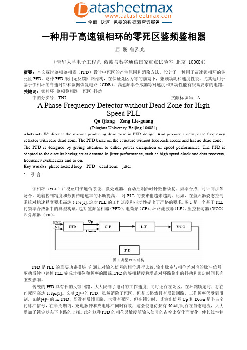
一种用于高速锁相环的零死区鉴频鉴相器屈 强 曾烈光(清华大学电子工程系 微波与数字通信国家重点试验室 北京 100084)摘要:本文探讨鉴频鉴相器(PFD )设计中死区的产生原因和消除方法。
设计了一种用于高速锁相环的零死区PFD 。
这种PFD 采用无反馈回路结构,在保证死区为零的前提下,兼顾功耗和速度性能。
尤其适用于基于锁相环的高速时钟和数据恢复电路(CDR )、高速频率合成器等对速度和抖动性能有很高要求的电路。
关键词:锁相环 鉴频鉴相器 死区 抖动中图分类号:TN7 文献标识码:AA Phase Frequency Detector without Dead Zone for HighSpeed PLLQu Qiang Zeng Lie-guang(Tsinghua University, Beijing 100084)Abstract: We discuss the reasons producing dead zone in PFD-design. And propose a new phase frequency detector with zero dead zone. The PFD bases on the structure without feedback access and has no dead zone 。
The PFD is designed by giving attention to either power dissipation or speed performance. The PFD is adapted to the circuits having strict demand in jitter performance, such as high speed clock and data recovery, frequency synthesizer and so on.Key words :phase locked loop PFD dead zone jitter1 引言锁相环(PLL )广泛应用于通信系统、微处理器、自动控制的时钟数据恢复、频率合成、时钟同步等场合。
基于NMF和相似度函数离群点检测的开题报告

基于NMF和相似度函数离群点检测的开题报告一、选题背景及意义随着大数据时代的到来,数据规模逐渐扩大,数据的复杂性也逐渐增加,导致传统的数据分析方法不再适用。
而离群点检测作为一种重要的数据分析方法,可以识别出数据中与主要数据分布不符的异常数据点,有着广泛的应用场景,如网络入侵检测、金融欺诈检测、医疗诊断等。
离群点检测方法主要分为基于统计学的方法、基于距离度量的方法、基于密度的方法以及基于聚类的方法等几种。
其中,基于聚类的方法通常需要先对数据进行聚类,再使用某些度量指标来检测簇外离群点。
但是这种方法的效率较低,而且对于高维稀疏数据的处理效果不佳。
因此,本文提出了一种新的离群点检测方法,该方法基于非负矩阵分解(NMF)和相似度函数。
该方法可以在高维稀疏数据的情况下快速准确地检测到离群点,实现对大规模数据的实时处理。
二、研究内容及方法本文的主要研究内容是基于NMF和相似度函数的离群点检测方法。
具体来说,本文将采用以下方法:1. 首先,本文将使用NMF方法将原始数据矩阵分解为两个非负矩阵,从而可以提取出数据的低维结构特征。
2. 然后,本文使用相似度函数来计算数据点之间的相似度。
本文将采用局部异常因子(LOF)算法作为相似度函数,因为该算法对离群点的检测比较准确。
3. 最后,本文将根据数据点的相似度值和低维特征向量来确定数据点是否为离群点。
本文使用Z-score来确定相似度值的阈值,如果相似度值小于阈值,则将该数据点标记为离群点。
三、预期研究成果本文的预期研究成果包括以下几点:1. 提出了一种基于NMF和相似度函数的离群点检测方法,该方法能够快速准确地检测到高维稀疏数据中的离群点,并且具有较高的检测准确率和实时性。
2. 通过实验验证,本文的方法与其他常用的离群点检测方法相比,具有更高的准确率和更快的检测速度。
3. 本文的方法可以应用于许多领域,如网络安全、金融、医疗等,为这些领域的数据分析和决策提供有力支持。
- 1、下载文档前请自行甄别文档内容的完整性,平台不提供额外的编辑、内容补充、找答案等附加服务。
- 2、"仅部分预览"的文档,不可在线预览部分如存在完整性等问题,可反馈申请退款(可完整预览的文档不适用该条件!)。
- 3、如文档侵犯您的权益,请联系客服反馈,我们会尽快为您处理(人工客服工作时间:9:00-18:30)。
360 1060-3425/96 $5.00 0 1996 IEEE
Proceedings of the 1996 Hawaii International Conference on System Sciences (HICSS-29) 1060-3425/96 $10.00 © 1996 IEEE
Introduction
Simulation has long been a way to understand,analyze, and predict the behavior of real world systems [l]. However, in order to develop large-scale simulation software for analysis and production we need to addressthe issuesof software manageability over the life-cycle of a simulation, and of execution speed for large systems simulations. Three technologies can be combined to successfully addressthese issues: objectoriented design, parallel processing, and parallel simulation. Object-oriented software engineering offers several advantages to software construction. It promotes and exploits modular design, data abstraction, inheritance, polymorphism, and delayed binding, which lead to key software qualities such as correctness, robustness, extendibility, reusability, efficiency, and portability [2]. Parallel processing, on the other hand, is a powerful technology which can deliver the performance required in today’ applications in a dramatically improved costs performance ratio [3]. Finally, parallel discrete event simulation (PDES) is a viable and attractive alternative for speeding up the execution of large and complex simulations and can be successfully applied to a large number of problems [43. In this paper we investigate the potential of using the object-oriented paradigm in the development of a parallel simulator and in its execution on a multiprocessor. In section 2 we present a layered approach to the construction of a framework for object-oriented parallel simulation, and describe a set of objects which collectively present our solution to the issues addressed each layer. In section 3 we discuss our design and by examine future directions in the development of environments for object-oriented parallel simulation.
The Abstract Parallel Machine
The Abstract Parallel Machine layer is the computation model which hides the specific characteristics of different parallel machine architectures. This model allows us to focus on the development of the parallel algorithm rather than on its implementation on a specific parallel machine, and it enables us to write efficient and portable parallel programs, thus overcoming the major difficulty of parallel programming. A nice representation of a parallel machine is the cluster NUMA multiprocessor model. According to this model, a multiprocessor consists of processor-memory modules interconnected by a network. A program initially consists of a single thread which sets up the computation structures and forks one or more threads on each of the processors. The threads communicate with each other and collaborate in solving the problem at hand in parallel. Our implementation of the Abstract Parallel Machine is based on the concept of an abstract processor. An abstract processor contains three subcomponents: a collection of LPs assignedto it; a pool of LPs which
Proceedings of the 29th Annual Hawaii International Conference on SystemSciences- 1996
Where Object-Oriented Technology Meets Parallel Simulation
Pavlos Konas Silicon Graphics Inc. Mountain View, CA 94043 Abstract
A Layered Approach to Parallel Simulation
Object-oriented software engineering, parallel processing, and parallel simulation address directly, but independently, the problems associatedwith developing and executing largescale simulation software. In this paper we integrate these technologies into a framework for object-oriented parallel simulation. This framework supports simulationists in developing modular, efficient, reusable and extendible parallel simulations, while, at the same time, it reduces the length of the development cycle, and it enhancesthe reliability of the produced systems. In order to reduce the complexity of the framework’ construction, we follow a layered approach. Such an s approach allows us to isolate each issue, and thus localize the methods addressing a specific issue. In addition, it enhances the maintபைடு நூலகம்inability, extensibility and modularity of the framework; it provides a clear separation of responsibilities; and it allows the concurrent involvement of researchersinterested in different areasof parallel simulation. One way to divide the process of developing and executing a parallel simulation into layers is shown in Figure 1. We have identified five layers each of which encapsulatesan issue we need to addressduring the development of the framework [5].