数字频率合成器的外文翻译
频率合成技术DDS介绍—AD系列

频率合成技术DDS介绍—AD系列常用的频率合成技术(FS, Frequency Synthesis)有模拟锁相环、数字锁相环、小数分频锁相环(fractional-N PLL Synthesis)等,直接数字合成(Direct Digital Synthesis-DDS)是近年来新的FS技术。
1.频率合成技术的发展现状由于直接数字频率合成器采用全数字方式实现频率合成,它直接对参考正弦时钟进行抽样和数字化,然后通过数字计算技术进行频率合成。
因此,它具有其它频率合成方法无法比拟的优点,频率转换速度快、频率分辨率高、输出相位连续、可编程、全数字化易于集成、体积小、功耗低等。
直接数字频率合成器在现代电子器件、通信技术、医学成像、无线、PCS/PCN 系统、雷达、卫星通信等众多领域得到了各方应用。
2.DDS与模拟PLL性能比较(1)输出分辨率小只要相位累加器的位宽足够大,参考时钟频率足够小,则分辨率可以很小:AD9850(参考时钟频率fc=125MHz)的相位累加器为32位,分辨率0.03Hz;AD9830(参考时钟频率fc=50MHz)的相位累加器为32位,分辨率0.012Hz;AD9852(参考时钟频率fc=300MHz)的相位累加器为48位,分辨率1*10-6Hz。
相反,模拟锁相环的合成器的分辨率为1KHz,它缺乏数字信号处理的固有特性。
(2)输出频率变换时间小一个模拟锁相环的频率变换时间主要是它的反馈环处理时间和压控振荡器的响应时间,通常大于1ms。
整片DDS合成器的频率变换时间主要是DDS的数字处理延迟,通常为几十个ns(AD9850最小43ns)。
(3)调频范围大一个负反馈环的带宽输出参考频率决定了模拟锁相环的稳定的调频范围;整片的DDS合成器是不受稳定性的影响的,在整个Nyquist频率范围内是可调的。
(4)相位噪声DDS优于PLL的最大优势就是它的相位噪声。
由于数字正弦信号的相位与时间成线形关系,整片的DDS输出的相位噪声比它的参考时钟源的相位噪声小。
直接数字频率合成器原理
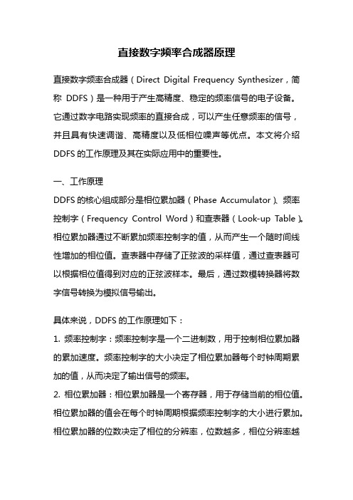
直接数字频率合成器原理直接数字频率合成器(Direct Digital Frequency Synthesizer,简称DDFS)是一种用于产生高精度、稳定的频率信号的电子设备。
它通过数字电路实现频率的直接合成,可以产生任意频率的信号,并且具有快速调谐、高精度以及低相位噪声等优点。
本文将介绍DDFS的工作原理及其在实际应用中的重要性。
一、工作原理DDFS的核心组成部分是相位累加器(Phase Accumulator)、频率控制字(Frequency Control Word)和查表器(Look-up Table)。
相位累加器通过不断累加频率控制字的值,从而产生一个随时间线性增加的相位值。
查表器中存储了正弦波的采样值,通过查表器可以根据相位值得到对应的正弦波样本。
最后,通过数模转换器将数字信号转换为模拟信号输出。
具体来说,DDFS的工作原理如下:1. 频率控制字:频率控制字是一个二进制数,用于控制相位累加器的累加速度。
频率控制字的大小决定了相位累加器每个时钟周期累加的值,从而决定了输出信号的频率。
2. 相位累加器:相位累加器是一个寄存器,用于存储当前的相位值。
相位累加器的值会在每个时钟周期根据频率控制字的大小进行累加。
相位累加器的位数决定了相位的分辨率,位数越多,相位分辨率越高,输出信号的频率分辨率也越高。
3. 查表器:查表器中存储了一个周期内的正弦波样本值(或余弦波样本值),通过查表器可以根据相位累加器的值得到对应的正弦波样本值。
4. 数模转换器:数模转换器将数字信号转换为模拟信号输出。
通常使用的是高速数模转换器,能够将数字信号以高速率转换为模拟信号输出。
二、应用领域DDFS在许多领域中都有广泛的应用,其中包括通信、雷达、测量、音频处理等。
1. 通信领域:在通信系统中,DDFS被广泛应用于频率合成器、频率调制器和频率解调器等模块中。
通过DDFS可以快速、精确地合成所需的信号频率,实现高速数据传输和频谱分析等功能。
直接数字频率合成芯片-概述说明以及解释
直接数字频率合成芯片-概述说明以及解释1.引言1.1 概述在概述部分,我们将介绍直接数字频率合成芯片的基本概念和作用。
直接数字频率合成芯片(Direct Digital Frequency Synthesizer,DDS)是一种用于产生不同频率信号的集成电路。
基于数字信号处理技术,DDS 芯片可以精确地生成各种频率和相位的信号。
相较于传统的模拟频率合成方法,DDS芯片具有更高的稳定性、精度和灵活性。
DDS芯片的工作原理基于数学算法和数字信号处理技术。
通过将数字信息转换为模拟信号输出,DDS芯片可以产生具有精确频率和相位的信号波形。
其核心部件包括相位积累器、数字控制振荡器和数模转换器。
相位积累器负责积累相位信息,数字控制振荡器则通过控制相位积累器的速率来实现不同频率信号的生成。
最后,数模转换器将数字信号转换为模拟信号输出。
直接数字频率合成芯片具有广泛的应用领域。
在通信系统中,DDS芯片被广泛应用于频率合成器、频率调制器、信号发生器等设备中。
其高精度和频率可调性使其成为无线通信、雷达、医学成像以及科学研究等领域的重要组成部分。
此外,DDS芯片还可以用于频率跟踪和频率锁定的系统中,提供更好的稳定性和精度。
总而言之,直接数字频率合成芯片通过数字信号处理技术实现高稳定性、精确性和灵活性的频率合成。
它在通信系统、科学研究和医学成像等领域具有广泛的应用前景。
随着科技的不断进步,我们可以期待直接数字频率合成芯片在未来的发展中发挥更重要的作用。
1.2 文章结构本文的结构主要分为引言、正文和结论三个部分。
在引言部分,我们将概述直接数字频率合成芯片,解释其基本原理和应用领域,并阐述本文的目的。
接着,在正文部分,首先我们将详细介绍直接数字频率合成芯片的原理,包括其工作原理、数字信号处理流程以及关键技术。
其次,我们将探讨直接数字频率合成芯片的应用领域,包括通信、雷达、电子音乐等方面,并论述其在各个领域中的优势和局限性。
最后,在结论部分,我们将总结直接数字频率合成芯片的优势,包括其高精度、灵活性强以及节省硬件开销等方面,并展望其未来的发展方向,包括对数字信号处理算法的优化、功耗降低以及更广泛的应用领域等方面的潜力。
DDS(DirectDigitalSynthesizer)直接数字式频率合成器
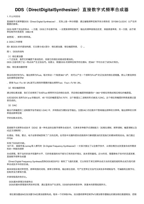
DDS(DirectDigitalSynthesizer)直接数字式频率合成器1. 什么叫DDS直接数字式频率器DDS(Direct Digital Synthesizer),实际上是⼀种分频器:通过编程频率控制字来分频系统(SYSM CLOCK)以产⽣所需要的频率。
DDS 有两个突出的特点,⼀⽅⾯,DDS⼯作在数字域,⼀旦更新频率控制字,输出的频率就相应改变,其跳频速率⾼;另⼀⽅⾯,由于频率控制字的宽度宽(48bit 或者更⾼),频率分辨率⾼。
2. DDS⼯作原理图1 是DDS 的内部结构图,它主要分成3 部分:相位累加器,相位幅度转换,()。
图 1,DDS的结构(1)相位累加器⼀个正弦波,虽然它的幅度不是线性的,但是它的相位却是线性增加的。
DDS 正是利⽤了这⼀特点来产⽣正弦信号。
如图 2,根据DDS 的频率控制字的位数N,把360° 平均分成了2的N次等份。
图2,相位累加器原理假设系统时钟为Fc,输出频率为Fout。
每次转动⼀个⾓度360°/2N,则可以产⽣⼀个频率为Fc/2N的正弦波的相位递增量。
那么只要选择恰当的频率控制字M,使得 Fout / Fc= M / 2N,就可以得到所需要的输出频率Fout,Fout = Fc*M / 2N。
(2)相位幅度转换通过相位累加器,我们已经得到了合成Fout 频率所对应的相位信息,然后相位幅度转换器把0°~360°的相位转换成相应相位的幅度值。
⽐如当DDS 选择为2V p-p 的输出时,45°对应的幅度值为0.707V,这个数值以⼆进制的形式被送⼊DAC。
这个相位到幅度的转换是通过查表完成的。
(3)DAC输出代表幅度的⼆进制数字信号被送⼊DAC 中,并转换成为模拟信号输出。
注意DAC 的位数并不影响输出频率的分辨率。
输出频率的分辨率是由频率控制字的位数决定的。
直接数字式频率合成技术(DDS)是⼀种先进的全数字频率合成技术,它具有多种数字式调制能⼒(如相位调制、频率调制、幅度调制以及I/Q正交调制等),在通信、导航、雷达、电⼦战等领域获得了⼴泛的应⽤。
数字频率合成器设计实例

数字频率合成器设计实例数字频率合成器设计实例数字频率合成器(Digital Frequency Synthesizer)是一种能够产生不同频率信号的设备。
它通过使用数字技术和数学算法来合成所需的频率,具有高精度和稳定性。
在本文中,我们将逐步介绍数字频率合成器的设计过程。
1. 设定所需频率范围:首先,确定所需合成的频率范围。
这取决于具体应用,例如音频处理、无线通信等。
假设我们的频率范围为1Hz到10kHz。
2. 确定采样率:采样率是指每秒钟对信号进行采样的次数。
根据香农抽样定理,采样率应大于信号最高频率的两倍。
在我们的例子中,最高频率为10kHz,因此选择采样率为至少20kHz。
3. 选择数字信号处理器(DSP):为了实现数字频率合成器,我们需要选择一种适合的DSP芯片。
DSP芯片能够高效地执行数字信号处理任务,例如信号生成和滤波。
选择一款性能强大且易于编程的DSP 芯片,以满足所需的合成要求。
4. 设计频率控制模块:频率控制模块是数字频率合成器的核心部分,用于生成所需频率的数字信号。
它通常由相位锁定环(PLL)和数字控制振荡器(NCO)组成。
a. 相位锁定环(PLL):PLL是一种控制系统,通过比较输入信号的相位和参考信号的相位差异来产生所需频率的输出信号。
通过调整参考信号的频率和相位,PLL可以实现精确的频率合成。
b. 数字控制振荡器(NCO):NCO是一种可编程振荡器,能够生成具有可变频率的数字信号。
通过调整输入的控制参数,NCO能够实现不同频率的信号合成。
5. 编程实现:根据DSP芯片的编程手册和软件开发工具,编写相应的代码实现频率控制模块。
通过配置PLL和NCO的参数,以及设置合适的参考信号,实现所需频率的合成。
6. 验证和调试:使用示波器或频谱分析仪等测试工具,验证合成的频率是否符合要求。
如果发现频率偏差或其他问题,可以通过调整PLL和NCO的参数来进行调试和校准。
7. 优化和改进:根据实际应用需求和反馈,对数字频率合成器进行优化和改进。
外文翻译及原文翻译咨询应用工程师33关于直接数字频率合成器的问题

本科毕业设计(论文)外文翻译译文学生姓名:王惠院(系):电子工程学院仪器系专业班级:测控0701指导教师:刘选朝完成日期: 20 11 年 3 月 7 日咨询应用工程师- 33关于直接数字频率合成器的问题作者Eva Murphy]Colm Slattery]什么是直接数字频率合成器?直接数字频率合成器(DDS)是一种产生模拟波形(通常是正弦波)的仪器,这种仪器是生成一个数字形式的时变信号,然后执行数字到模拟的转换。
因为用一个DDS设备操作主要是数字形式,所以它可以提供输出频率之间的快速转换,较高的频率分辨率并且可以在一个宽频带上进行操作。
随着设计和工艺技术的进步,现在的DDS器件都非常小巧,在低功率下也可以工作。
为什么我们要使用直接数字频率合成器(DDS)?难道就没有其他产生频率的简单方法吗?能够准确地产生和控制各种频率和轮廓的波形的能力已成为一个通用于多个行业重要要求。
在通信系统中能否利用良好的杂散性提供低相位噪声可变频率的活跃来源,或仅产生用于工业或生物医学测试设备的应用的频率刺激,便利、简洁和低成本是重要的设计考虑因素。
频率产生的多种可能性对设计师来说是开放的,从锁相回路(PLL)——极高频率合成的基础技术,到以数模转换器(DAC)的动态编制程序输出来产生低频任意波形。
但是DDS技术迅速在解决频率(或波形)产生的通信和工业应用要求上得到接受,因为单芯片集成电路器件可以简单的产生可编程模拟输出波形,具有较高的分辨率和精度。
此外,在这两种工艺技术和设计的不断改进也使得成本和功耗较从前降低了许多。
例如,AD9833——基于DDS的可编程波形发生器(图1)在V的电压下工作工作具有25 MHz的时钟,消耗的最大功率为30毫瓦。
图1 单片波形发生器使用直接数字频率合成器(DDS)的主要优点有哪些?像AD9833 之类的DDS器件都可通过一个高速串行外设接口(SPI)进行编程,并且只需要一个外部时钟来生成简单的正弦波。
外文翻译数字频率合成器

附录2:外文原文,译文Modulating Direct Digital Synthesizer In the pursuit of more complex phase continuous modulation techniques, the control of the output waveform becomes increasingly more difficult with analog circuitry. In these designs, using a non-linear digital design eliminates the need for circuit board adjustments over yield and temperature. A digital design that meets these goals is a Direct Digital Synthesizer DDS. A DDS system simply takes a constant reference clock input and divides it down a to a specified output frequency digitally quantized or sampled at the reference clock frequency. This form of frequency control makes DDS systems ideal for systems that require precise frequency sweeps such as radar chirps or fast frequency hoppers. With control of the frequency output derived from the digital input word, DDS systems can be used as a PLL allowing precise frequency changes phase continuously. As will be shown, DDS systems can also be designed to control the phase of the output carrier using a digital phase word input. With digital control over the carrier phase, a high spectral density phase modulated carrier can easily be generated.This article is intended to give the reader a basic understanding of a DDS design, and an understanding of the spurious output response. This article will also present a sample design running at 45MHz in a high speed field programmable gate array from QuickLogic.A basic DDS system consists of a numerically controlled oscillator (NCO) used to generate the output carrier wave, and a digital to analog converter (DAC) used to take the digital sinusoidal word from the NCO and generate a sampled analog carrier. Since the DAC output is sampled at the reference clock frequency, a wave form smoothing low pass filter is typically used to eliminate alias components. Figure 1 is a basic block diagram of a typical DDS system generation of the output carrier from the reference sample clock input is performed by the NCO. The basic components of the NCO are a phase accumulator and a sinusoidal ROM lookup table. An optional phase modulator can also be include in the NCO design. This phase modulator will add phase offset to the output of the phase accumulator just before the ROM lookup table. This will enhance the DDS system design by adding the capabilities to phase modulate the carrier output of the NCO. Figure 2 is a detailed block diagram of a typical NCO design showing the optional phase modulator.FIGURE 1: Typical DDS System.FIGURE 2: Typical NCO Design.To better understand the functions of the NCO design, first consider the basic NCO design which includes only a phase accumulator and a sinusoidal ROM lookup table. The function of these two blocks of the NCO design are best understood when compared to the graphical representation of Euler’s formula ej wt = cos( wt) + jsin( wt). T hegraphical representation of Euler’s formula, as shown in Figure 3, is a unit vector rotating around the center axis of the real and imaginary plane at a velocity of wrad/s. Plotting the imaginary component versus time projects a sine wave while plotting the real component versus time projects a cosine wave. The phase accumulator of the NCO is analogous, or could be considered, the generator of the angular velocity component wrad/s. The phase accumulator is loaded, synchronous to the reference sample clock, with an N bit frequency word.This frequency word is continuously accumulated with the last sampled phase value by an N bit adder. The output of the adder is sampled at the reference sample clock by an N bit register. When the accumulator reaches the N bit maximum value, the accumulator rolls over and continues. Plotting the sampled accumulator values versus time produces a saw tooth wave form as shown below in Figure 3. FIGURE 3 Euler’s Equation Represented GraphicallyThe sampled output of the phase accumulator is then used to address a ROM lookup table of sinusoidal magnitude values. This conversion of the sampled phase to a sinusoidal magnitude is analogous to the projection of the real or imaginary component in time. Since the number of bits used by the phase accumulator determines the granularity of the frequency adjustment steps, a typical phase accumulator size is 24 to 32 bits. Since the size of the sinusoidal ROMtable is directly proportional to the addressing range, not all 24 or 32 bits of the phase accumulator are used to address the ROM sinusoidal table. Only the upper Y bits of the phase accumulator are used to address the sinusoidal ROM table, where Y < N bits and Y is typically but not necessarily equal to D, and D is the number of output magnitude bits from the sinusoidal ROM table.Since an NCO outputs a carrier based on a digital representation of the phase and magnitude of the sinusoidal wave form, designers have complete control over frequency, phase, and even amplitude of the output carrier. By adding a phase port and a phase adder to the basic NCO design, the output carrier of the NCO can be M array phase modulated where M equals the number of phase port bits and where M is less than or equal to the Y number of bits used to address the sinusoidal ROM table. For system designs that require amplitude modulation such as QAM, a magnitude port can be added to adjust the sinusoidal ROM table output. Note that this port is not shown in Figure 2 and that this feature is not demonstrated in the sample QuickLogic FPGA design. Finally, frequency modulation is a given with the basic NCO design. The frequency port can directly adjust the carrier output frequency. Since frequency words are loaded into the DDS synchronous to the sample clock, frequency changes are phase continuous.Although DDS systems give the designer complete control ofcomplex modulation synthesis, the representation of sinusoidal phase and magnitude in a non-linear digital format introduces new design complexities. In sampling any continuous-time signal, one must consider the sampling theory and quantization error.To understand the effects of the sampling theory on a DDS system, it is best to look at the DDS synthesis processes in both the time and frequency domain. As stated above, the NCO generates a sinusoidal wave form by accumulating the phase at a specified rate and then uses the phase value to address a ROM table of sinusoidal amplitude values. Thus, the NCO is essentially taking a sinusoidal wave form and sampling it with the rising or falling edge of the NCO input reference sampling clock. Figure 4 shows the time and frequency domain of the NCO processing. Note that this representation does not assume quantization.Based on the loaded frequency word, the NCO produces a set of amplitude output values at a set period. The frequency domain representation of this sinusoid is an impulse function at the specified frequency. The NCO, however, outputs discrete digital samples of this sinusoid at the NCO reference clock rate. In the time domain, the NCO output is a function of the sampling clock edge strobes multiplied by the sinusoid wave form producing a train of impulses at the sinusoid amplitude. In the frequency domain, the sampling strobes of the reference clock produce a train of impulses at frequencies of K times theNCO clock frequency where K = ... - 1, 0, 1, 2 .... Since the sampling clock was multiplied by the sinusoid in the time domain, the frequency domain components of the sinusoid and the sampling clock need to be convolved to produce the frequency domain representation of the NCO output.The frequency domain results are the impulse function at the fundamental frequency of the sinusoid and the alias impulse functions occurring at K times the NCO clock frequency plus or minus the fundamental frequency. The fundamental and alias component occur at: K*Fclk - FoutK*Fclk + FoutWhere K = ... -1, 0 , 1, 2 ..... and K = 0 is the NCO sinusoid fundamental frequencyFout is the specified NCO sinusoid output frequencyFclk is the NCO reference clock frequencyFIGURE 4 NCO Output Representation Time and Frequency Domain The DAC of the DDS system takes the NCO output values and translates these values into analog voltages. Figure 4 shows the time and frequency domain representations of the DAC processing starting with the NCO output. The DAC output is a sample and hold circuit that takes the NCO digital amplitude words and converts the value into an analog voltage and holds the value for one sample clock period. The timedomain plot of the DAC processing is the convolution of the NCO sampled output values with a pulse of one sample clock period. The frequency domain plot of the sampling pulse is a sin(x)/x function with the first null at the sample clock frequency. Since the time domain was convolved, the frequency domain is multiplied. This multiplication dampens the NCO output with the sin(x)/x envelope. This attenuation at the DAC output can be calculated as follows and a sample output spectrum is shown in Figure 5:Atten(F) = 20log[(sin(pF/Fclk)/pF/Fclk)] Where F is the output frequency Fclk is the sample clock frequencyFIGURE 5: DAC Output Representation in Time and Frequency Domain Aside from the sampling theory, the quantization of the real values into digital form must also be considered in the performance analysis of a DDS system. The spurious response of a DDS system is primarily dictated by two quantization parameters. These parameters are the phase quantization by the phase accumulator and the magnitude quantization by the ROM sinusoidal table and the DAC.As mentioned above, only the upper Y bits of the phase accumulator are used to address the ROM lookup table. It should be noted, however, that using only the upper Y bits of the phase accumulator introduces a phase truncation. When a frequency word containing a non-zero value in the lower (N-Y-1:0) bits is loaded into the DDS system, the lowernon-zero bits will accumulate to the upper Y bits and cause a phase truncation. The frequency at which the phase truncation occurs can be calculated by the following:Ftrunc = FW(N-Y- 1:0)/2N-Y* Fclk.A phase truncation will periodically (at the Ftrunc rate) phase modulate the output carrier forward 2p/28 to compensate for frequency word granularity greater than 2Y. The phase jump caused by the accumulation of phase truncated bits produces spurs around the fundamental.These spurs are located plus and minus the truncation frequency from the fundamental frequency and the magnitude of the spurs will be - 20log(2Y)dBc. A sample output of a phase truncation spur is shown in Figure 5.In a typical NCO design, the ROM sinusoidal table will hold a ¼ sine wave (0 , p/2) of magnitude values. The ROM table is generated by taking all possible phase value addresses and map to a real magnitude sine value rounded to the nearest D bits. Thus, the maximum error output is ±- ½ LSB giving a worst case spur of -20log(2D)dBc.Like the NCO ROM table, a DAC quantizes the digital magnitude values. A DAC, however, outputs an analog voltage corresponding to the digital input value. When designing the NCO sinusoidal ROM table, one should take some empirical data on the DAC linearity to betterunderstand the interaction between the ROM table and the DAC. The quantization for a DAC is specified against an ideal linear plot of digital input versus analog output. Two linearity parameters, differential and integral linearity, are used to specify a DAC’s p erformance.Differential linearity is the output step size from bit to bit. A DAC must guarantee a differential linearity of a maximum 1 LSB. When an input code is increased, the DAC output must increase. If the DAC voltage does not increase versus an increase digital input value, the DAC is said to be missing codes. Thus, a 10 bit DAC that has a differential linearity of greater that 1 LSB is only accurate to 9 or less bits. The number of accurate output bits will specify the DDS spurious performance as -20log(2dl) where dl is the number differential linear bits..Integral linearity is a measure of the DAC’s overall linear performance versus an ideal linear straight line. The straight line plot can be either a “best straight line” where DC offsets are pos sible at both the min and max outputs of the DAC, or the straight line can cross the end points of the min and max output values. A DAC will tend to have a characteristic curve that is traversed over the output range. Depending on the shape and symmetry (symmetry about the half way point of the DAC output) of this curve, output harmonics of the DDS fundamental output frequency will be produced. As these harmonics approach andcross the Nyquist frequency of Fclk/2, the harmonics become under sampled and reflect back into the band of interest, 0 to Fclk/2. This problem is best illustrated by setting the NCO output to Fclk/4 plus a slight offset. The third harmonic will fall minus 3 folds the small offset from the fundamental and the second harmonic will cross the Nyquist frequency by 2 folds the small offset leaving a reflected image back in the band of interest A sample plot of this frequency setup is shown in Figure 5.Other DAC characteristic that will produce harmonic distortion is any disruption of the symmetry of the output wave form such as a different rise and fall time. These characteristics can typically be corrected by board components external to the DAC such as an RF transformer, board layout issues, attenuation pads etc.Given the complexities of the DDS system, engineers should consider implementing the design using separate devices for the numerically controlled oscillator, the digital to analog converter, and the low pass filter. This approach allows for signal observation at many points in the system, yet is compact enough to be practical as an end-solution. Alternatively, the discrete implementation can serve as a prototyping vehicle for a single-chip mixed signal ASIC.The author developed a version of the design using a Harris HI5721 evaluation board for the DAC. The NCO at the heart of the DDS design,and a random generator to test signal modulation, was implemented into about 65% of a QuickLogic field programmable gate array (FPGA). This FPGA, a QL16x24B 4000-gate device, was chosen for its high performance, ease-of-use, and powerful development tools.The NCO design included following:Developed in Verilog with the 8 bit CLA adder schematiccaptured and net listed to Verilog32 bit frequency word input32 phase accumulator pipelined over 8 bits8 bit phase moudulation word input8 bit sine ROM look-up tableThe design was described mostly in Verilog, with an 8 bit carry look ahead adder modified from QuickLogic’s macro library netlisted to Verilog. The whole design cycle was less than four days (two days to describe the design and a day and a half to prototype the hardware). Everything worked perfectly the first time, with the design running at an impressive 45MHz as predicted by the software simulation tools.Plots used in the article to illustrate DDS performance parameters were provided from the test configuration.Figure 6 below shows the external IO interface to the NCO design .The function of each signal is described in the following table.Signal Function TableFigure 6: The External IO InterfaceTop LevelThe top level of the NCO design instantiates the functional blocks of the NCO design and the PN generator block.PN GeneratorThis module is not part of the NCO design but is used to produce a sample random data pattern to modulate the carrier output. This module uses the PNCLK input to clock two Gold code 5 bit PN generators. The outputs of the PN generators are IDATA and QDATA outputs.The lower level block of this NCO design consist of a synchronous frequency word input register, a synchronous phase word input register, a 32 bit pipe lined phase accumulator, an 8 bit phase adder, and a sin lockup table. A detailed description of each of the NCO blocks and thePN generator are provided in the following sections.Load Frequency WordThe load frequency word block is a synchronizing loading circuit. The FREQWORD[31:0] input drives a the data input to the 32 bit fwreg register that is sampled on the rising edge of the FWWRN write strobe. The FWWRN strobe also drives the data input to a metastable flip flop fwwrnm that is used in conjunction with a synchronous register fwwrns to produce a FWWRN rising edge strobe. This rising edge strobe loadp1 is then piped for an additional 3 clock cycles producing the load strobes loadp2, loadp3, and loadp4. The load strobes are used to signal when to update the synchronous pipe line 8 bit registers pipefw1, pipefw2, pipefw3, and pipefw4 to the sampled frequency word content. The pipe line registers are concatenated to produce the 32 bit synchronous frequency word output SYNCFREQ[31:0] that is staggered to compensate for the 32 bit pipe lined phase adder.Phase Word AccumulatorThe phase accumulator block is a 32 bit accumulator that is pipe lined in 8 bit sections. This module instanciates a schematic captured carry lock ahead CLA adder that has a carry in and carry out port. The synchronous frequency word, staggered to match the pipe lined accumulator, is loaded into the B input of the CLA adders. The sum output of the CLA adders are registered in the pipe registered with theoutput tied back to the A input of the CLA adders. The carry output of the CLA adders is registered in the pipec registers with the output tied to the next most significant CLA adder carry input. The most significant sum output register pipe4 is assigned to the PHASE output port giving a phase value quantized to 8 bits. A digital sine and cosine value is also calculated from the pipe4 register and brought out of the chip as SIN and COS.Load Phase WordThe load phase word block is a synchronizing loading circuit. The PHASEWORD[7:0] input drives the data input to the 32 bit pwreg register that is sampled on the rising edge of the PWWRN write strobe. The PWWRN strobe also drives the data input to a metastable flip flop pwwrnm that is used in conjunction with a synchronous register pwwrns to produce a FWWRN rising edge strobe. This rising edge strobe load is used to signal when to update the synchronous phase word register phswd. The phswd register is assigned to the synchronous phase word output SYNCPHSWD[7:0].Phase ModulatorThe phase modulator block is used to phase offset the phase accumulator 8 bit quantized output with the synchronous phase word from the load phase word block. This module instantiates a CLA adder with the A input tied to the synchronous phase output and the B inputtied to the phase accumulator output. The sum output of the adder is registered in the mphsreg register and assigned to the MODPHASE output port. A modulated version of the sine and cosine values are calculated and brought out of the chip as MSIN and MCOS.Sine LockupThis module takes the modulated phase value form the phase modulator block and translated the quantized 8 bit value into a sine wave form amplitude value quantized to 8 bits. The translation from phase to amplitude is performed by a sine ROM table that in instantiated in this module. The ROM table is reduced to a ¼ of the symmetrical sine wave form and the MSB of the sine wave form is equivalent to the modulated phase module performs the calculations to reconstruct a complete period of the sine wave form f rom the ¼ representation of the ROM table and the MSB of the modulated phase input. To better understand the processing of this module, consider the following. The modulated phase value is a 0 to 2p value quantized to 8 bits 2p/28. The quantized value for p/2, p, 3p/2, and 2p are 0x3F, 0x7F, 0xBF, and 0xFF. The amplitude values for 0 to p/2 is stored in the ROM table. The amplitude values for p/2 to p are the ROM table output in the reverse order. The amplitude values for p to 3p/2 are the same output as the amplitude value from 0 to p/2 with the output from the ROM table inverted. Finally the amplitude value for 3p/2 to 2p are the same as for pto 3p/2 with the ROM table accessed in reverse.This module manages the address values to the ROM table and the amplitude outputs to form the complete period of the sine wave form. The first process of generating the sine wave function is the addressing of the ROM table such that phase angles p/2 to p and 3p/2 to 2p are addressed in the reverse order. Reverse addressing is accomplished by simply inverting the ROM table address input vector. The phase modulated address input is inverted when the MODPHASE[6] is one and is then registered in the phaseadd register. The phase address is used to address the ROM sine table with the output registered in the qwavesin_ff register. To construct the negative amplitude values of the sine wave form, the MSB of the modulate phase word input is registered twice in modphase_msb1_ff and modphase_msb2_ff, compensating for the two cycle latency of the phaseadd and qwavesin_ff registers. The delayed MSB bit is used to invert the ROM table output when one. The altered ROM table output and the invert of the delayed modulated phase word MSB are finally registered in by the dac_ff register and then assigned to the DACOUT output port.Sine ROM TableThis module is the sine wave form ROM table. This table converts the phase word input to a sine amplitude output. To conserve area, only ¼ of the symmetrical sine wave form is stored in the ROM. The sine valuesstored in this table are the 0 to p/2 unsigned values quantized to 8 bits. Thus, the ROM table requires a 6 bit phase address input and outputs a 7 bit amplitude output. The sinlup module processes the phase and amplitude values to produce a complete sine period.Dan Morelli has over 9 years of design and management experience. His areas of expertise include spread spectrum communications (involving GPS, TDRSS, and , PC chip set and system architecture, cell library development (for ECL devices) and ASIC development. He has been published and has multiple patents awarded and pending. Dan currently works for Accelent Systems Inc., an electronic design consulting company, where he is a founder and the VP of Engineering.数字频率合成器在探讨许多复杂的相位持续的调制技术中,对模拟电路中输出波形的操纵已经愈来愈困难。
dds直接数字频率合成器(优秀+)
南京理工大学电子线路课程设计直接数字频率合成器D D S(题名和副题名)(学号)指导教师姓名姜萍老师学院电子工程与光电技术学院年级2012级专业名称通信工程论文提交日期2014.12摘要直接数字信号合成器(DDS)是一种从相位概念出发直接合成所需要波形的新的频率合成技术。
与传统的频率合成器相比,DDS具有低成本、低功耗、高分辨率和快速转换时间等优点。
本文使用DDS的方法设计一个任意频率的正弦信号发生器,具有频率控制、相位控制、测频、切换波形、动态显示、使能开关以及AM调制等功能。
利用QuartusII7.0中VHDL语言完成计算机设计、仿真等工作,然后使用由Altera公司开发的Cyclone III 系列EP3C25F324C8实验箱实现电路,用示波器观察输出波形。
本文使用模块化的设计理念,将整体电路分为9个子模块设计,分别为:分频模块、频率预置与调节模块、频率累加寄存模块、相位预置与调节模块、相位累加寄存模块、sin函数波形存储模块、余弦波方波三角波锯齿波波形选择模块、测频与译码显示模块、AM调制模块。
其后,本文给出了本实验的计算机仿真图与示波器输出图,并进行结果分析。
最后在文末给出了本实验所设计的电路的使用说明书。
关键词:直接数字信号合成器、DDS、AM调制、VHDL、测频AbstractDirect digital synthesizer (DDS) is a new technology of frequency synthesis ,which comes from the concept of the phase, to directly synthetize the required waveform . Compared with the traditional frequency synthesizer, DDS has the advantages of lower cost, lower power consumption, higher resolution and faster switching time etc..DDS method is used to design a direct digital synthesizer to synthetize the sin function of any frequency in this paper, with functions of frequency control, phase control frequency measurement, waveform switching, dynamic display, switch enable and AM modulation. Using VHDL language in the QuartusII7.0, we complete the design, simulation and other works by computer, and then use the EP3C25F324C8 experimental box of Cyclone III series developed by the Altera to implement the design, and finally observe the output waveform in oscilloscope.In this paper, the modular design concept is used, and the whole circuit is divided into 9 sub module design, respectively is: frequency division module, frequency adjusting module, frequency cumulative and register module, phase presetting and adjusting module, phase cumulative and register module, sin function waveform memory module, cos wave, square wave, triangle wave, sawtooth waveform selection module, frequency measurement and decoding display module, the AM modulation module.Then, the computer simulation diagram and the output of the oscilloscope graphs of this experiment is given in this paper, followed by the results analysis. Finally, we give the experimental instructions of the circuit design at the end of the paper.Keywords: direct digital synthesizer, DDS, AM modulation, VHDL, frequency measurement目录摘要 (2)Abstract (3)1 绪论 (7)1.1 DDS的发展概况 (7)1.2 选题背景及意义 (7)1.3 课题研究现状 (8)1.4 本文主要工作 (8)2 实验平台Cyclone III EP3C25F324C5 (10)2.1 Cyclone III (10)2.1.1 Cyclone III 系列产品介绍 (10)2.1.2 Cyclone III EP3C25F324C5 开发板原理图 (11)3 DDS基本原理总电路图 (12)3.1 DDS的基本结构 (12)3.2 DDS的基本原理 (12)3.3 DDS总电路封装图 (14)3.4 本章小结 (16)4 DDS各子模块设计原理 (17)4.1 分频模块 (17)4.1.1 48分频子模块 (18)4.1.2 1000分频子模块 (19)4.1.3 0.5分频子模块 (20)4.2 频率预置与调节模块 (21)4.3 频率累加寄存模块 (22)4.3.1 12位累加器子模块 (23)4.3.2 12位寄存器子模块 (24)4.4 相位预置与调节模块 (25)4.5 相位累加与寄存模块 (25)4.5.1 12位累加器子模块 (26)4.5.2 12位寄存器子模块 (26)4.6 sin波形存储模块 (27)4.6.1 sin_rom子模块 (27)4.6.2 10位寄存器子模块 (28)4.7 余弦波、方波、三角波、锯齿波波形选择模块 (29)4.7.1 cos_rom、rect_rom、square_rom、sawtooth_rom波形存储子模块 (29)4.7.2 波形4选1输出子模块 (30)4.7.3 10位寄存器子模块 (31)4.8 测频与译码显示模块 (31)4.8.1 10进制计数器子模块 (32)4.8.2 测频子模块 (33)4.8.3 译码显示子模块 (34)4.9 AM调制模块 (36)4.9.1 载波产生子模块 (37)4.9.2 调制波乘法与加法子模块 (38)4.9.3 载波乘法子模块 (39)4.9.4 已调波与调制波二选一显示子模块 (40)5 DDS调试仿真与下载 (42)5.1 DDS仿真 (42)5.2 AM调制仿真 (43)5.3 DDS管脚设定与下载运行 (44)6 DDS示波器结果显示 (46)7 DDS使用说明书 (49)8 结论 (50)8.1 论文工作总结 (50)8.2 论文工作展望 (50)致谢 (51)参考文献 (52)1绪论1.1D DS的发展概况DDS是直接数字式频率合成器(Direct Digital Synthesizer)的英文缩写。
- 1、下载文档前请自行甄别文档内容的完整性,平台不提供额外的编辑、内容补充、找答案等附加服务。
- 2、"仅部分预览"的文档,不可在线预览部分如存在完整性等问题,可反馈申请退款(可完整预览的文档不适用该条件!)。
- 3、如文档侵犯您的权益,请联系客服反馈,我们会尽快为您处理(人工客服工作时间:9:00-18:30)。
英文原文Modulating Direct Digital Synthesizer In the pursuit of more complex phase continuous modulation techniques, the control of the output waveform becomes increasingly more difficult with analog circuitry. In these designs, using a non-linear digital design eliminates the need for circuit board adjustments over yield and temperature. A digital design that meets these goals is a Direct Digital Synthesizer DDS. A DDS system simply takes a constant reference clock input and divides it down a to a specified output frequency digitally quantized or sampled at the reference clock frequency. This form of frequency control makes DDS systems ideal for systems that require precise frequency sweeps such as radar chirps or fast frequency hoppers. With control of the frequency output derived from the digital input word, DDS systems can be used as a PLL allowing precise frequency changes phase continuously. As will be shown, DDS systems can also be designed to control the phase of the output carrier using a digital phase word input. With digital control over the carrier phase, a high spectral density phase modulated carrier can easily be generated.This article is intended to give the reader a basic understanding of a DDS design, and an understanding of the spurious output response. This article will also present a sample design running at 45MHz in a high speed field programmable gate array from QuickLogic.A basic DDS system consists of a numerically controlled oscillator (NCO) used to generate the output carrier wave, and a digital to analog converter (DAC) used to take the digital sinusoidal word from the NCO and generate a sampled analog carrier. Since the DAC output is sampled at the reference clock frequency, a wave form smoothing low pass filter is typically used to eliminate alias components. Figure 1 is a basic block diagram of a typical DDS system design.The generation of the output carrier from the reference sample clock input is performed by the NCO. The basic components of the NCO are a phase accumulator and a sinusoidal ROM lookup table. An optional phase modulator can also be include in the NCO design. This phase modulator will add phase offset to the output of the phase accumulator just before the ROM lookup table. This will enhance the DDS system design by adding thecapabilities to phase modulate the carrier output of the NCO. Figure 2 is a detailed block diagram of a typical NCO design showing the optional phase modulator.FIGURE 1: Typical DDS System.FIGURE 2: Typical NCO Design.To better understand the functions of the NCO design, first consider the basic NCO design which includes only a phase accumulator and a sinusoidal ROM lookup table. The function of these two blocks of the NCO design are best understood when compared to the graphical representat ion of Euler’s formula ej wt = cos( wt) + jsin( wt). The graphical representation of Euler’s formula, as shown in Figure 3, is a unit vector rotating around the center axis of the real and imaginary plane at a velocity of wrad/s. Plotting the imaginary component versus time projects a sine wave while plotting the real component versus time projects a cosine wave. The phase accumulator of the NCO is analogous, or could be considered, the generator of the angular velocity component wrad/s. The phase accumulator is loaded, synchronous to the reference sample clock, with an N bit frequency word.This frequency word is continuously accumulated with the last sampled phase value by an N bit adder. The output of the adder is sampled at the reference sample clock by an N bit register. When the accumulator reaches the N bit maximum value, the accumulator rolls over and continues. Plotting the sampled accumulator values versus time produces a saw tooth wave form as shown below in Figure 3.FIGURE 3 Euler’s Equation Re presented GraphicallyThe sampled output of the phase accumulator is then used to address a ROM lookup table of sinusoidal magnitude values. This conversion of the sampled phase to a sinusoidal magnitude is analogous to the projection of the real or imaginary component in time. Since the number of bits used by the phase accumulator determines the granularity of the frequency adjustment steps, a typical phase accumulator size is 24 to 32 bits. Since the size of the sinusoidal ROM table is directly proportional to the addressing range, not all 24 or 32 bits of the phase accumulator are used to address the ROM sinusoidal table. Only the upper Y bits of the phase accumulator are used to address the sinusoidal ROM table, where Y < N bits and Y is typically but not necessarily equal to D, and D is the number of output magnitude bits from the sinusoidal ROM table.Since an NCO outputs a carrier based on a digital representation of the phase and magnitude of the sinusoidal wave form, designers have complete control overfrequency, phase, and even amplitude of the output carrier. By adding a phase port and a phase adder to the basic NCO design, the output carrier of the NCO can be M array phase modulated where M equals the number of phase port bits and where M is less than or equal to the Y number of bits used to address the sinusoidal ROM table. For system designs that require amplitude modulation such as QAM, a magnitude port can be added to adjust the sinusoidal ROM table output. Note that this port is not shown in Figure 2 and that this feature is not demonstrated in the sample QuickLogic FPGA design. Finally, frequency modulation is a given with the basic NCO design. The frequency port can directly adjust the carrier output frequency. Since frequency words are loaded into the DDS synchronous to the sample clock, frequency changes are phase continuous.Although DDS systems give the designer complete control of complex modulation synthesis, the representation of sinusoidal phase and magnitude in a non-linear digital format introduces new design complexities. In sampling any continuous-time signal, one must consider the sampling theory and quantization error.To understand the effects of the sampling theory on a DDS system, it is best to look at the DDS synthesis processes in both the time and frequency domain. As stated above, the NCO generates a sinusoidal wave form by accumulating the phase at a specified rate and then uses the phase value to address a ROM table of sinusoidal amplitude values. Thus, the NCO is essentially taking a sinusoidal wave form and sampling it with the rising or falling edge of the NCO input reference sampling clock. Figure 4 shows the time and frequency domain of the NCO processing. Note that this representation does not assume quantization.Based on the loaded frequency word, the NCO produces a set of amplitude output values at a set period. The frequency domain representation of this sinusoid is an impulse function at the specified frequency. The NCO, however, outputs discrete digital samples of this sinusoid at the NCO reference clock rate. In the time domain, the NCO output is a function of the sampling clock edge strobes multiplied by the sinusoid wave form producing a train of impulses at the sinusoid amplitude. In the frequency domain, the sampling strobes of the reference clock produce a train of impulses at frequencies of K times the NCO clock frequency where K = ... - 1, 0, 1, 2 .... Since the sampling clock was multiplied by the sinusoid in the time domain, the frequency domain components of the sinusoid and the sampling clock need to be convolved to produce the frequency domain representation of the NCO output.The frequency domain results are the impulse function at the fundamental frequency of the sinusoid and the alias impulse functions occurring at K times the NCO clock frequency plus or minus the fundamental frequency. The fundamental and alias component occur at:K*Fclk - FoutK*Fclk + FoutWhere K = ... -1, 0 , 1, 2 ..... and K = 0 is the NCO sinusoid fundamental frequencyFout is the specified NCO sinusoid output frequencyFclk is the NCO reference clock frequencyFIGURE 4 NCO Output Representation Time and Frequency DomainThe DAC of the DDS system takes the NCO output values and translates these values into analog voltages. Figure 4 shows the time and frequency domain representations of the DAC processing starting with the NCO output. The DAC output is a sample and hold circuit that takes the NCO digital amplitude words and converts the value into an analog voltage and holds the value for one sample clock period. The time domain plot of the DAC processing is the convolution of the NCO sampled output values with a pulse of one sample clock period. The frequency domain plot of the sampling pulse is a sin(x)/x function with the first null at the sample clock frequency. Since the time domain was convolved, the frequency domain is multiplied. This multiplication dampens the NCO output with the sin(x)/x envelope. This attenuation at the DAC output can be calculated as follows and a sample output spectrum is shown in Figure 5:Atten(F) = 20log[(sin(pF/Fclk)/pF/Fclk)] Where F is the output frequency Fclk is the sample clock frequencyFIGURE 5: DAC Output Representation in Time and Frequency Domain Aside from the sampling theory, the quantization of the real values into digital form must also be considered in the performance analysis of a DDS system. The spurious response of a DDS system is primarily dictated by two quantization parameters. These parameters are the phase quantization by the phase accumulator and the magnitude quantization by the ROM sinusoidal table and the DAC.As mentioned above, only the upper Y bits of the phase accumulator are used to address the ROM lookup table. It should be noted, however, that using only the upper Y bits of the phase accumulator introduces a phase truncation. When a frequencyword containing a non-zero value in the lower (N-Y-1:0) bits is loaded into the DDS system, the lower non-zero bits will accumulate to the upper Y bits and cause a phase truncation. The frequency at which the phase truncation occurs can be calculated by the following:Ftrunc = FW(N-Y- 1:0)/2N-Y* Fclk.A phase truncation will periodically (at the Ftrunc rate) phase modulate the output carrier forward 2p/28 to compensate for frequency word granularity greater than 2Y. The phase jump caused by the accumulation of phase truncated bits produces spurs around the fundamental.These spurs are located plus and minus the truncation frequency from the fundamental frequency and the magnitude of the spurs will be - 20log(2Y)dBc. A sample output of a phase truncation spur is shown in Figure 5.In a typical NCO design, the ROM sinusoidal table will hold a ¼ sine wave (0 , p/2) of magnitude values. The ROM table is generated by taking all possible phase value addresses and map to a real magnitude sine value rounded to the nearest D bits. Thus, the maximum error output is ±- ½ LSB giving a worst case spur of -20log(2D)dBc.Like the NCO ROM table, a DAC quantizes the digital magnitude values. A DAC, however, outputs an analog voltage corresponding to the digital input value. When designing the NCO sinusoidal ROM table, one should take some empirical data on the DAC linearity to better understand the interaction between the ROM table and the DAC. The quantization for a DAC is specified against an ideal linear plot of digital input versus analog output. Two linearity parameters, differential and integral linearity, are used to specify a DAC’s performance.Differential linearity is the output step size from bit to bit. A DAC must guarantee a differential linearity of a maximum 1 LSB. When an input code is increased, the DAC output must increase. If the DAC voltage does not increase versus an increase digital input value, the DAC is said to be missing codes. Thus, a 10 bit DAC that has a differential linearity of greater that 1 LSB is only accurate to 9 or less bits. The number of accurate output bits will specify the DDS spurious performance as -20log(2dl) where dl is the number differential linear bits..Integral linearity is a measure of the DAC’s overall linear performance versus an ideal linear straight line. The straight line plot can be either a “best straight line” where DC offsets are possible at both the min and max outputs of the DAC, or thestraight line can cross the end points of the min and max output values. A DAC will tend to have a characteristic curve that is traversed over the output range. Depending on the shape and symmetry (symmetry about the half way point of the DAC output) of this curve, output harmonics of the DDS fundamental output frequency will be produced. As these harmonics approach and cross the Nyquist frequency of Fclk/2, the harmonics become under sampled and reflect back into the band of interest, 0 to Fclk/2. This problem is best illustrated by setting the NCO output to Fclk/4 plus a slight offset. The third harmonic will fall minus 3 folds the small offset from the fundamental and the second harmonic will cross the Nyquist frequency by 2 folds the small offset leaving a reflected image back in the band of interest A sample plot of this frequency setup is shown in Figure 5.Other DAC characteristic that will produce harmonic distortion is any disruption of the symmetry of the output wave form such as a different rise and fall time. These characteristics can typically be corrected by board components external to the DAC such as an RF transformer, board layout issues, attenuation pads etc.Given the complexities of the DDS system, engineers should consider implementing the design using separate devices for the numerically controlled oscillator, the digital to analog converter, and the low pass filter. This approach allows for signal observation at many points in the system, yet is compact enough to be practical as an end-solution. Alternatively, the discrete implementation can serve as a prototyping vehicle for a single-chip mixed signal ASIC.The author developed a version of the design using a Harris HI5721 evaluation board for the DAC. The NCO at the heart of the DDS design, and a random generator to test signal modulation, was implemented into about 65% of a QuickLogic field programmable gate array (FPGA). This FPGA, a QL16x24B 4000-gate device, was chosen for its high performance, ease-of-use, and powerful development tools.The NCO design included following:Developed in Verilog with the 8 bit CLA adder schematiccaptured and net listed to Verilog32 bit frequency word input32 phase accumulator pipelined over 8 bits8 bit phase moudulation word input8 bit sine ROM look-up tableThe design was described mostly in Verilog, with an 8 bit carry look ahead addermodified from QuickLogic’s macro library netlisted to Verilog. The whole design cycle was less than four days (two days to describe the design and a day and a half to prototype the hardware). Everything worked perfectly the first time, with the design running at an impressive 45MHz as predicted by the software simulation tools.Plots used in the article to illustrate DDS performance parameters were provided from the test configuration.Figure 6 below shows the external IO interface to the NCO design .The function of each signal is described in the following table.Signal Function TableFREQWORD[31:0] This input is the frequency control word to the NCO. This word controls the phase accumulator rate, and thus, the output frequency of the DACOUT sinusoidal wave form. The output carrier frequency is calculated by the following :PHASEWORD[7:0] This input is the phase modulation control word to the NCO. This word controls the phase offset following the phase accumulator. This phase offset is used to phase modulate the output carrier.FWWRN This input is the low asserted frequency word write strobe. This strobe input registers the FREQWORD input on the rising edge. This strobe can be asynchronous to the SYSCLK.SYSCLK This is the reference system clock input to the NCO. This clock is the sampling clock of the output carrier.PNCLK This input is the pseudo-noise generator clock input. This clock sets the data rate of the I and Q data outputs.RESETN This input is a low asserted global reset. When asserted, the internal phase and frequency word registers are cleared stopping the output carrier at 0 radians.DACOUT[7:0] This output is the sinusoidal DAC amplitude word. This word is valid on the rising edge of the DACCLK. The sinusoidal wave form output is represented by the following :f(t) = sin(2pFout(t) + Pout)DACCLK This output is the DAC clock strobe. This clock is the SYSCLK feed back to an output pin compensating for the latency of the NCO IO pins. The DACOUT amplitude words will be valid on the rising edge of the DACCLK.SIN This output is a single bit digital sine wave output. This sine wave output comes from the MSB of the phase accumulator. The output frequency of this pin is controlled by the frequency word input.COS This output is a single bit digital cosine wave output. This cosine wave output comes form the MSB and next most significant bit of the phase accumulator. The output frequency of this pin is controlled by the frequency word input.MSIN This output is a single bit digital sine wave output. This sine wave output comes from the MSB of the phase modulator. The output frequency of this pin is controlled by the frequency word input and phase offset bythe phase word input. This sine wave output is the same as the SIN output with a phase offset of plus 2p/28 * PHASEWORD.MCOS This output is a single bit digital cosine wave output. This cosine wave output comes form the MSB and next most significant bit of the phase modulator. The output frequency of this pin is controlled by the frequency word input and the phase offset by the phase word input. This cosine wave outputis the same as the COS output with a phase offset of plus 2p/28 * PHASEWORD.IDATA This output is a 25 - 1 pseudo noise random pattern. This output is not a functional part of the NCO design but used to demonstrate phasemodulation using the phase port.QDATA This output is a 25 - 1 pseudo noise random pattern. This output is not a functional part of the NCO design but used to demonstrate phase modulation using the phase port.Figure 6: The External IO InterfaceTop Level (dds.v)The top level of the NCO design instantiates the functional blocks of the NCO design and the PN generator block.PN Generator (pngen.v)This module is not part of the NCO design but is used to produce a sample random data pattern to modulate the carrier output. This module uses the PNCLK input to clock two Gold code 5 bit PN generators. The outputs of the PN generators are IDATA and QDATA outputs.The lower level block of this NCO design consist of a synchronous frequencyword input register, a synchronous phase word input register, a 32 bit pipe lined phase accumulator, an 8 bit phase adder, and a sin lockup table. A detailed description of each of the NCO blocks and the PN generator are provided in the following sections.Load Frequency Word (loadfw.v)The load frequency word block is a synchronizing loading circuit. The FREQWORD[31:0] input drives a the data input to the 32 bit fwreg register that is sampled on the rising edge of the FWWRN write strobe. The FWWRN strobe also drives the data input to a metastable flip flop fwwrnm that is used in conjunction with a synchronous register fwwrns to produce a FWWRN rising edge strobe. This rising edge strobe loadp1 is then piped for an additional 3 clock cycles producing the load strobes loadp2, loadp3, and loadp4. The load strobes are used to signal when to update the synchronous pipe line 8 bit registers pipefw1, pipefw2, pipefw3, and pipefw4 to the sampled frequency word content. The pipe line registers are concatenated to produce the 32 bit synchronous frequency word output SYNCFREQ[31:0] that is staggered to compensate for the 32 bit pipe lined phase adder.Phase Word Accumulator (phasea.v)The phase accumulator block is a 32 bit accumulator that is pipe lined in 8 bit sections. This module instanciates a schematic captured carry lock ahead CLA adder that has a carry in and carry out port. The synchronous frequency word, staggered to match the pipe lined accumulator, is loaded into the B input of the CLA adders. The sum output of the CLA adders are registered in the pipe registered with the output tied back to the A input of the CLA adders. The carry output of the CLA adders is registered in the pipec registers with the output tied to the next most significant CLA adder carry input. The most significant sum output register pipe4 is assigned to the PHASE output port giving a phase value quantized to 8 bits. A digital sine and cosine value is also calculated from the pipe4 register and brought out of the chip as SIN and COS.Load Phase Word (loadpw.v)The load phase word block is a synchronizing loading circuit. The PHASEWORD[7:0] input drives the data input to the 32 bit pwreg register that is sampled on the rising edge of the PWWRN write strobe. The PWWRN strobe also drives the data input to a metastable flip flop pwwrnm that is used in conjunction with a synchronous register pwwrns to produce a FWWRN rising edge strobe. This risingedge strobe load is used to signal when to update the synchronous phase word register phswd. The phswd register is assigned to the synchronous phase word output SYNCPHSWD[7:0].Phase Modulator (phasemod.v)The phase modulator block is used to phase offset the phase accumulator 8 bit quantized output with the synchronous phase word from the load phase word block. This module instantiates a CLA adder with the A input tied to the synchronous phase output and the B input tied to the phase accumulator output. The sum output of the adder is registered in the mphsreg register and assigned to the MODPHASE output port. A modulated version of the sine and cosine values are calculated and brought out of the chip as MSIN and MCOS.Sine Lockup (sinlup.v)This module takes the modulated phase value form the phase modulator block and translated the quantized 8 bit value into a sine wave form amplitude value quantized to 8 bits. The translation from phase to amplitude is performed by a sine ROM table that in instantiated in this module. The ROM table is reduced to a ¼ of the symmetrical sine wave form and the MSB of the sine wave form is equivalent to the modulated phase input.This module performs the calculations to reconstruct a complete period of the sine wave form from the ¼ representation of the ROM table and the MSB of the modulated phase input. To better understand the processing of this module, consider the following. The modulated phase value is a 0 to 2p value quantized to 8 bits 2p/28. The quantized value for p/2, p, 3p/2, and 2p are 0x3F, 0x7F, 0xBF, and 0xFF. The amplitude values for 0 to p/2 is stored in the ROM table. The amplitude values for p/2 to p are the ROM table output in the reverse order. The amplitude values for p to 3p/2 are the same output as the amplitude value from 0 to p/2 with the output from the ROM table inverted. Finally the amplitude value for 3p/2 to 2p are the same as for p to 3p/2 with the ROM table accessed in reverse.This module manages the address values to the ROM table and the amplitude outputs to form the complete period of the sine wave form. The first process of generating the sine wave function is the addressing of the ROM table such that phase angles p/2 to p and 3p/2 to 2p are addressed in the reverse order. Reverse addressing is accomplished by simply inverting the ROM table address input vector. The phase modulated address input is inverted when the MODPHASE[6] is one and is then registered in the phaseadd register. The phase address is used to address the ROM sinetable with the output registered in the qwavesin_ff register. To construct the negative amplitude values of the sine wave form, the MSB of the modulate phase word input is registered twice in modphase_msb1_ff and modphase_msb2_ff, compensating for the two cycle latency of the phaseadd and qwavesin_ff registers. The delayed MSB bit is used to invert the ROM table output when one. The altered ROM table output and the invert of the delayed modulated phase word MSB are finally registered in by the dac_ff register and then assigned to the DACOUT output port.Sine ROM Table (romtab.v)This module is the sine wave form ROM table. This table converts the phase word input to a sine amplitude output. To conserve area, only ¼ of the symmetrical sine wave form is stored in the ROM. The sine values stored in this table are the 0 to p/2 unsigned values quantized to 8 bits. Thus, the ROM table requires a 6 bit phase address input and outputs a 7 bit amplitude output. The sinlup module processes the phase and amplitude values to produce a complete sine period.Dan Morelli has over 9 years of design and management experience. His areas of expertise include spread spectrum communications (involving GPS, TDRSS, and 802.11), PC chip set and system architecture, cell library development (for ECL devices) and ASIC development. He has been published and has multiple patents awarded and pending. Dan currently works for Accelent Systems Inc., an electronic design consulting company, where he is a founder and the VP of Engineering.中文译文数字频率合成器在探讨许多复杂的相位连续的调制技术中,对模拟电路中输出波形的控制已经越来越困难。