时滞系统的内模控制设计及应用
大时滞过程控制系统及MATLAB仿真
大时滞过程控制系统及MATLAB仿真大时滞过程控制系统是指系统的时滞(Time Delay)较大,也就是系统输入和输出之间存在较长的延迟。
这种系统广泛应用于化工、生物、环境等领域,具有较强的非线性和不确定性。
因此,研究大时滞过程控制系统及其在MATLAB中的仿真对于理论和应用的深入研究具有重要意义。
大时滞过程控制系统的建模和控制是一个复杂的过程。
首先,需要对该系统进行建模,包括确定系统的输入输出关系、非线性特性以及时滞等。
然后,选择合适的控制策略,设计控制器来实现对系统的稳定性、鲁棒性和性能的优化。
最后,通过MATLAB进行仿真验证控制效果。
在大时滞过程控制系统中,常用的控制策略包括PID控制器、模糊控制器和自适应控制器等。
PID控制器是一种经典的控制策略,通过调节比例、积分和微分增益来实现对系统的控制;模糊控制器能够处理非线性和不确定性,通过模糊推理和模糊规则库来实现对系统的控制;自适应控制器则是根据系统的模型和参数实时调整控制器的参数,适应系统的变化。
在MATLAB中,可以利用Simulink工具箱进行大时滞过程控制系统的仿真。
Simulink是一种基于图形化界面的仿真环境,可以通过搭建模型、设置参数和运行仿真来模拟系统的动态行为。
在Simulink中,可以选择适当的模型来构建系统的输入输出关系,通过设置时滞参数和控制策略参数来模拟实际系统的时滞和控制效果。
通过仿真,可以观察系统的响应曲线、稳定性、鲁棒性和性能等指标,验证控制策略的有效性和优化效果。
同时,MATLAB还提供了许多函数和工具箱来支持大时滞过程控制系统的建模和控制。
例如,可以利用Control System Toolbox进行系统建模和控制器设计,利用System Identification Toolbox进行系统辨识,利用Robust Control Toolbox进行鲁棒性分析和控制设计等。
这些工具能够方便地进行系统的分析、优化和验证,为大时滞过程控制系统的研究提供了强大的支持。
基于内模控制的PID控制器在大时滞过程中的应用研究
基于内模控制的PID 控制器在大时滞过程中的应用研究陶睿,肖术骏,王秀,朱学峰(华南理工大学自动化科学与工程学院,广州,510640)摘要:基于内模控制的PID 控制器,只有一个可调参数,且该参数直接与系统的闭环响应速度和回路的鲁棒性有关,克服了常规PID 控制参数整定复杂的缺点,易于为工程技术人员所掌握。
城市供水出水浊度过程是一个大惯性、大时滞、非线性、时变以及随机干扰多的难控对象。
而把IMC-PID 控制器应用在该对象上,仿真结果表明可以取得较理想的控制效果。
关键字:浊度控制; 大时滞过程; 内模控制; PID 控制; 中图分类号:TP273The Study on PID Controller Based on Internal Model Control in the Applications of LargeTime Delay SystemTAO Rui, XIAO Shujun, WANG Xiu, ZHU Xuefeng(S outh China University of Technology, College of Automation Science and Engineering,Guangzhou, Guangdong, 510640)Abstract: PID controller which based on internal model control can set the system using only one adjustable parameter. And the parameter direct related to the response speed of closed loop and the robustness of loop. It is better to conventional PID controller in noise immunity and complexity.The MIC-PID controller can greatly improve the control results and be easy to control by the engineers and technicians. The turbidity control system of municipal water supply system is a non-linear and time-variant process with a large time constant and large dead time ,which is always difficult to control. When adding the MIC-PID controller to it can obtain a better control effect.Key words: Turbidity control; Large time delay system; Internal model control; PID controller;1 引言 在现代工业过程的控制中,PID 控制算法的到了广泛的应用。
大时滞过程控制方法及应用分析
大时滞过程控制方法及应用分析诸葛晓春南宁化工股份有限公司,广西南宁530001摘要:本文对常用控制方法中的PID控制、Smith预估控制、Dahlin控制以及现代控制方法中的内膜控制、预测控制等各种控制方法及特点进行介绍,并对大时滞过程控制方法的应用进行分析。
关键词:大时滞;控制方法;应用分析时滞是工业生产中常见的现象。
存在时滞,意味着系统的扰动不能及时地在控制作用上得到反映,而是延迟一段时间后才在对象输出上反映出来。
因此,选择适当的控制方法,能有效控制时滞系统,保证工业生产的安全可靠性。
1.经典控制方法1.1Smith预估控制Smith预估控制方法是由瑞典科学家Smith提出的,它的基本控制思路是预估出系统在扰动状态下的特征,再通过构建函数,以向内反馈的形式,使常规控制器的时滞得到补偿,达到控制作用超前反映在对象输出上的目的。
从理论上讲,Smith预估控制法可以避免时滞现象带来的影响,然而在实际的实践中却大相径庭。
被控制对象的精确的数学模型是Smith预估控制器得以实现的基础,因此,当数学模型与控制对象存在偏差时,控制器便达不到预期的控制效果,甚至还有恶化的可能。
1.2Dahlin控制Dahlin控制是由Dahlin在1968年提出的一种数字控制方法,它主要是针对大纯滞后系统,即对当纯滞后时间τ与对象时间常数T之比(τ/T),大于0.5甚或超过1.0时的对象进行控制。
它的基本思路是使得闭环系统等效为一个一阶惯性环节加纯滞后环节,并期望整个闭环系统的纯滞后时间和被控对象的纯滞后时间相同。
Dahlin算法方法比较简单,只要根据传递函数设计出合适的且可以实现的数字调节器,就能够有效地克服纯滞后的不利影响。
但采用Dahlin控制会出现振铃现象,即闭环系统的输出以指数形式较快地趋向稳态值,而数字控制器的输出则以二分之一的采样频率大幅度的衰减震荡。
这样一来,会造成执行机构大幅度的摆动,加剧磨损,甚至引起系统的稳定性下降。
时滞系统几种控制策略研究
时滞系统几种控制策略研究时滞系统几种控制策略研究时滞系统是一类在实际控制中常见的系统,其特点是系统状态变量在对应的输出值上受到时间延迟的影响。
时滞系统在工程领域广泛应用,例如飞行器、机器人等。
然而,由于时滞的存在,时滞系统往往容易出现不稳定、震荡和性能下降的问题,因此如何有效地控制时滞系统,降低时滞对系统性能的影响成为了一个重要的研究方向。
针对时滞系统的控制策略研究,主要包括经典控制方法、自适应控制方法和智能控制方法等。
经典控制方法中,最常用的是PID控制器。
PID控制器是一种基于比例、积分、微分控制的经典控制策略,它能够对系统的误差进行调节。
然而,对于时滞系统,传统PID控制器存在不足之处,因为时滞会导致控制信号滞后,从而影响系统的稳定性。
因此,需要对PID控制器进行改进,使其能够对时滞系统进行有效的控制。
自适应控制方法通过根据系统的特性实时调整控制器的参数,从而适应系统的变化。
其中,模型参考自适应控制(Model Reference Adaptive Control, MRAC)是一种常用的方法。
MRAC通过在线估计系统的模型,并根据估计的模型来调整控制器的参数,从而实现对时滞系统的控制。
此外,自适应滑模控制(Adaptive Sliding Mode Control, ASMC)也是一种常用的控制方法。
ASMC通过引入滑模面,并根据系统误差的变化调整滑模面的位置,以降低时滞对系统的影响。
智能控制方法中,模糊控制和神经网络控制是常见的策略。
模糊控制是一种基于模糊逻辑推理的控制方法,通过将人类的经验和知识转化为模糊规则,来对系统进行控制。
神经网络控制是一种通过训练神经网络来实现对系统的控制的方法,神经网络可以学习系统的非线性映射关系,并通过适当的训练来调整权值,从而实现对时滞系统的控制。
在实际应用中,不同的控制策略可以结合使用,以实现更好的控制效果。
例如,可以将PID控制器和模糊控制器结合,利用PID控制器对系统进行粗略调节,再利用模糊控制器进行微调,从而达到更好的控制效果。
一阶线性时滞系统的内模控制设计
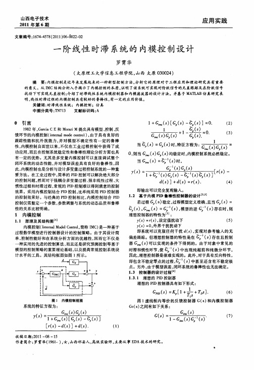
1 G s[ () G() = . + () s 一 psJ 0
() 2
南 一 ㈤ 丽 ¨葡 - 【 o 3 ・ ) -
当 ( ( 时特 方 为 : 1 s ) s ,征 程 : )
0则当 G s () , () s均稳定时, 内模控制系统必然稳定。 当 G ()= s
关键词 : 时滞线性 系统 ;内模控制 ;仿真 中图分类号 :N 1 文献标识码 : T 73 A
0 引言
18 9 2年 , a i CE和 Moa Gra c rrM提 出具有模型 、 i 控制 、 反 馈环节的内模控制(ne l d ot 1 , i ma moecn o ) 由于 具有 良好 的 t r 跟踪性能和抗外 扰能力 , 对模 型不 确定性 有一 定 的鲁棒 并 性, 内模控制 自面世 以来 , 不仅在 工业过程 控制 中获得 了成 功应用 , 而且在控制系统稳定性 和鲁棒性理论分析方面 也具 有一定的优势。尤其 是多变量 内模 控制可 以直接 调试整个 闭环系统的动态性能 , 并对 模型误差 具有 良好 的鲁棒 性 , 因 此, 内模控制也是分析与设 计多变量 过程控制 系统的一 种重 要方法。在工业过程中 , 简单的 PD控制可以解决绝大部 分 I 的控制问题 , 然而对于强耦合多变量过程 、 强非线性过程 、 大 惯性过程和时滞过程 , 常规的 PD控制难 以得到满意的控制 I 效果 。采用内模控制结合 PD控制 , I 比单纯采用 PD控 制器 I 的控制效果好。与经典的 PD控制 相 比, I 内模控 制结合 PD I 控制仅需整定一个参数 , 参数调整与系统的动态 品质 和鲁棒 性的关系 比较明确。
G ̄ s [ + + s . e ()= 1 ]
』1
一阶时滞系统内模控制的优化分析
一阶时滞系统内模控制的优化分析詹庄春【摘要】Based on the IMC -PID principle , by using the practical PID model , the combination of theoretical calculation and practical engineering was realized .Through the different degree of first order delay system param-eter setting , the value range of lambda is determined .By utilizing the NCD , a large amount of calculation can be performed , which provides an effective way for the parameter optimization .By giving a concrete example , the system showed good control performance .And after a general analysis , the general rule of the internal model control was obtained , which provides a reference to engineering design .%基于IMC-PID原理,采取实际应用的PID模型,实现了理论算式与工程实际的结合。
对不同时滞程度的一阶系统进行参数整定,确定了λ的取值范围。
利用NCD解决了大量计算问题,为参数优化提供了有效途径。
通过设计举例,显示出系统具有良好的控制性能。
再经过一般性分析,得出了内模控制的一般规律,以供工程设计参考。
【期刊名称】《安徽理工大学学报(自然科学版)》【年(卷),期】2016(036)001【总页数】5页(P70-74)【关键词】一阶时滞;IMC-PID;NCD;参数整定【作者】詹庄春【作者单位】华南农业大学珠江学院,广东广州 510900【正文语种】中文【中图分类】TP214一阶时滞系统普遍存在于过程控制当中,对于时滞程度较大的系统,单纯采用经典PID控制,其参数很难整定;最经典的控制方式有Simth预估控制法,但该方法对模型误差和滞后时间较敏感,而系统的动态过程和干扰使被控对象的实际模型很难精确。
时滞系统的内模控制设计及应用
Ke Vaue = 1; y l
} e ei K y D oe < 38 l s f( eA C d 8) {
Ke Vaue = 2; y l
}
e ei( eA C d < 18 l K y D oe s f 2)
{
Ke Vaue = 3; y l
} es e Vau = 4 le K y le 口应用 实例 口
下的按键键 值 。图中 电容 C 1用 于消 除抖 动 和干扰 信 号 J 。 用该方法对键盘状态进行扫描成本低 、 电路布线简单 。
{
Dea m (0 ; / 时 ly s 1 ) / 延
_
仪器 仪表用户
1m 0 s的消抖处理
3 软件 设计
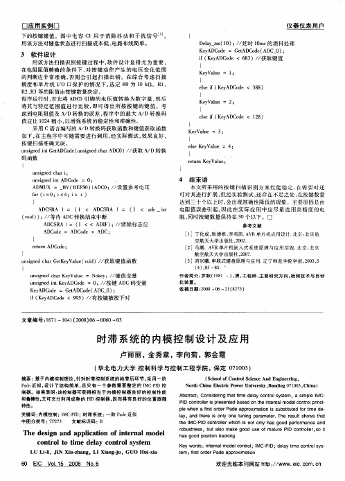
用该方法扫描识别 按键过程 中 , 软件设 计显得尤 为重要 , 在电阻阻值精确 的条件 下 , 按键 动作产 生 的电压 变化范 围 对 的判断应非 常准确 , 否则 会 引起扫描 出错 。在 综合 考虑扫 描 精度和单 片机 IO口保 护 的情 况下 , / 选定 R 0为 1 Q。R 、 0k 1 R 、 3等的阻值由按键数量决定 。 2R 程 宁 运行 时 , 首先 将 A C I 的 电 压 值 转 换 为 数 字 量 , 后 D 0弓 脚 然 将其与特定 范 围值 进行 比较 , 即可 得 出所 按按 键 的键 值。考 虑到电阻阻值及 A D转换的误 差 , / 程序 中的最大 A D转 换码 / 值应 比 12 04稍小 , 以增强系统的稳定性和准确性 。 采用 C语 言编写的 A D转 换码获取 函数和键值获取 函数 / 如下 , 主程序 中可随需要进行调 用 , 在 经实 际测试 , 效果 良好 , 按 键 扫 描 准 确无 误 。 us ndit eA C d ( ni e hr D 0 / 获取 A D转换 ni e tD o e u s dc a A C ) / g nG n g / 码 函数
高阶时滞工业系统的自适应内模控制
Design of Adaptive Internal M odel Controller for the H igh-O rder Industrial System s with Tim e Delay
LIU Si—jie ,WANG Kai—yang ,YIN Er—xin
(1.Huadian Electric Power Research Institute,Hangzhou Zhejiang 310030,China;
2 高 阶 时滞 系ቤተ መጻሕፍቲ ባይዱ 自适应 内模 控制 器设 计
本文提 出的高阶时滞系统 自适应 内模 控制器 ,是基 于不 同工况 数学模 型的模 型参数 ,应 用最 优线 性拟合 的方 式 ,以
1 引 言 对于大 多数工 业 对象 而 言 ,由于被 控 对 象 常具 有 纯 迟
延 、大惯 性 、变模 型 等复 杂特 性 ,常 规 PID控 制器 控 制效 果 较差 。内模控制 …作 为一 种先 进控 制理 论 ,对迟 延大 、惯 性 大的被控对象具 有较 好 的控 制效 果 ,但该 控 制方 式对 被 控 对象模型 的依赖 程度较 大 ,当被控 对象 模型发 生 变化 时 ,控 制效果变差 ,甚至 出现 系统不 稳定 的状 况 ,为 了保证 系统 的 稳定性 ,不得不加入 带有 较大 时 间常数 的滤 波环 节 ,这又 使 得系统 的动 态特性变 差 ,系统 输 出无法 及时 跟踪 系统输 入 。 为解决上述 问题 ,有学 者提出了一种滤 波器参数 自适应 的 内 模控制器 j,该控制方法将 带有较大纯迟延 的一 阶对象 的 内 模控制 器 ,经过数 学推 导 ,等效 变换 为 以滤波 器参数 为 变量 的 PI控制器 ,再应用模糊控制 对滤波器 时 间常数进 行修改 , 实现 了变滤波 器参 数 的 内模 控 制 ,但 对于 一般 工 业 过程 而 言 ,为了获得较高 的模 型精度 ,较难 应用 一 阶系统作 为 预估
锅炉液位时滞系统的内模控制
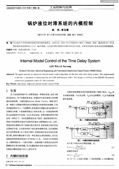
1 引 言
在工业控制领域 当中, 时滞系统是一种难控系统 , 也是当前
内模控 制原理 图及等价结构图如图 1 和图 2 所示 ,GM () ICs
为 内模控制器 , (为过程 ,G( 为过程模型 ,G (为扰动通 Gs ) 0) s d) s
道传递函数。
研究 的热点。 对于时滞 系统来说 , 常规的PD I调节器难以获得满 意的控制效果。内模控制( t nl dlC nrl I e a Moe ot ,简称 I ) nr o MC
维普资讯
自 化 术 应 20 年 7 第2 动 技 与 用》08 第2卷 期
工 业 控 制 与应 用
n sr du ty Con r l d Ap i a i n to an pl t s c o
锅炉 液 位 时滞 系统 的 内模 控 制
2 e 】 I 倒 & pI i s 4 l 打 eoA舾r T sf A p 卸0 n
维普资讯
工 业 控 制 与 应 用
n us r n r n p iat ns d ty Co tol d Ap l i a c o
Ab t a t Th a e r s n s a mp o e n e n lmo e o to l o i m o h is o d rt e a y t m . T e i r v m e t s r c : e p p rp e e t n i r v d i t r a d lc n r l g rt a h f r e fr t r e me d l y s se . h mp o e n t i
关 键 词 : 滞 ;改进 内模控 制 ;I 时 TAE
中图分类号 :T 2 3 2 P 7 .2ቤተ መጻሕፍቲ ባይዱ
时滞光电跟踪系统鲁棒内模PID控制器设计
时滞光电跟踪系统鲁棒内模PID控制器设计赵志诚;刘志远;张井岗【摘要】针对时滞光电跟踪提出了一种内模PID(IMC-PID)控制器设计与参数整定的解析方法.首先建立了系统的一阶时滞积分(FODI)模型,并用二阶加时滞(SOPDT)模型进行逼近,然后利用一阶Taylor表达式代替系统模型中的时滞项,导出了控制器参数的整定规则.特别是为了保证系统的鲁棒性,可以根据最大灵敏度解析计算内模PID控制器的可调参数λ_n.仿真结果表明,与常规方法相比,所提方法不仅提供了较好的设定值跟踪和扰动抑制特性,而且对于系统参数摄动具有更好的鲁棒性.另外,实验结果也证实了该方法能够提高系统跟踪性能和跟踪精度.【期刊名称】《光电工程》【年(卷),期】2010(037)001【总页数】7页(P30-36)【关键词】内模PID;光电跟踪系统;时滞系统【作者】赵志诚;刘志远;张井岗【作者单位】哈尔滨工业大学控制科学与工程系,哈尔滨,150001;太原科技大学自动化系,太原,030024;哈尔滨工业大学控制科学与工程系,哈尔滨,150001;太原科技大学自动化系,太原,030024【正文语种】中文【中图分类】V5560 IntroductionOpto-electronic tracking system is a complex equipment which mainly includes photoelectric detection,signal processing, control systems, precision machinery and other parts. It is widely applied in the filed of civilian and military industry such as NC machine tools, astronomical observation, shooting range measurement, weapons control, and flight simulators etc[1]. For opto-electronic tracking system, a good servo performance, such as high-accuracy, high-speed, non-overshoot and no vibration, is necessary [2]. Furthermore, in order to keep stability for parameter perturbation system, a high robustness is also very important.In other words, it is expected to achieve both performance and robustness in opto-electronic tracking system. However, considering the disturbance and uncertainty in the system, the conventional PID control is difficult to meet the requirement of the control performance effectively.So, based on the PID control, many improved PID type control schemes are researched in [1][3][4],respectively. A multi-mode control algorithm was proposed in [3]. The algorithm is expressed as follows: if the error is large, the saturation control is adopted; if the error is medium, the square root control is adopted; and if the error is small, the PID control is adopted. Paper [4]proposed a fuzzy-PID control approach, which could shorten the transient time, reduce the overshoot and improve the tracking accuracy and robustness of control system. Paper[1]proposed a single neuron fuzzy PID control method. Thus the trackingsystem not only has the capability of learning and self-adaptation, but also has better dynamic performance and steady-state performance than that of PID control. But in the above-mentioned schemes, the measurement time-delay of image tracker is not considered.To deal with the measurement time-delay, various advanced control approaches are presented. Paper [5]proposed an adaptive prediction and compensation method, which applied LMS algorithm and an adaptive filter with transverse structure to delay prediction compensation. The simulation results demonstrated the effectiveness of the method. Paper [6]introduced the method of predictive filtering in opto-electronic tracking system. Paper [7]adopted a state prediction and estimation method based on robust H∞ filter for opto-electronic tracking system.The experimental results show that the proposed method has high accuracy and good robustness. Whereas, the predictive filtering method needs complex calculation, and it easily causes the arithmetic to diverge.To find a simple design method of the PID type controller with a significant performance improvement has become an important research issue for control engineers. Because of the simplicity and improved performance of the IMC-based tuning rules, the analytically derived IMC-PID tuning methods have attracted the attention of industrial users [8]. The IMC-PID tuning rule has only one user-defined tuning parameter, which is directly related to the closed-loop performance and robustness of the system. The PID controller design has been discussed extensively in the literature for first-order plus delay time and second-order plus delay timestable/unstable process[8-10]. But the design of a simple and robust controller with improved performance has not yet been fully achieved. This paper focuses on the design of IMC-PID controller for an opto-electronic tracking system with time-delay. The system can be represented by a first-order delayed integrating (FODI)model. According to the principle of IMC, an analytical design approach of PID controller is proposed. Then, the tuning method of the controller parameter is given. Moreover, the maximum sensitivity can be applied to guarantee the robustness of the system. The simulation and experimental results show that this scheme is easy to be realized and has better performance than the conventional approach.1 Design of IMC-PID Controller for Time-delay SystemThe block diagram of IMC system is shown in Fig.1, where Q(s)is the internal model controller, G(s)is the process, M(s)is the model, and R(s),Y(s), D(s)is the set point, output and external disturbance of the system respectively. According to the design procedure for IMC system, the model is factorized asWhere M-(s) and M+(s)are the portions of the model inverted and not inverted, respectively. M+(s)is usually a non-minimum phase and contains delay time and/or right half plane zeros of M(s), while M-(s)is stable and of minimum phase with no predictors. The IMC controller Q(s)takes the formWhere f(s)is a user specified low-pass filter and usually chosen asWhere r is sufficiently large in order to guarantee that the IMC controller Q(s)is proper. Also, λ is the time constant, determined by the expected system performance. A smaller λ provides faster closed-loop response, while a l arger λ is also less sensitive to model mismatches.Fig.1 Block diagram of IMCFig.2 Equivalent block diagram of IMCIMC structure in Fig.1 can be reduced to the equivalent classic feedback structure shown in Fig.2. Gc(s)is a feedback controller. The relation between the feedback controller Gc(s)and the internal model controller Q(s)can be expressed as follows:System dynamics are often approximated by low order transfer function models for ease in controller design.The dynamics of a large number of industrial controlled objects can be represented by FOPDT and SOPDT transfer function models of the forms:The IMC filter structure exploited here is given asSo, the IMC controller can be obtained, and the corresponding feedback controller isIn order to make the resulting controller in Eq.(9)has a PID controller structure, the time-delay term is approximated by the simple first orderTaylor expansion.Let the forms of the PI and PID controllers beWhere Kp, Ti and Td are the proportional gain, the integral time constant and the derivative time constant,respectively. Table 1 shows the IMC-based PI/PID controller settings for the FOPDT and SOPDT models, where λn = λ/θ.Table 1 Settings of the controller for FOPDT and SOPDT modelsM(s)Kp Ti Td τ τ K s τs 1 e+-θK(λ+θ)=θ(λ+)k τ n 1-θ e s τs+2 22 K s ξτ+1K(λξτ 2ξτ 2+2ξτ θ)=θ(λ+)Kn 1ξ τ22 Design of IMC-PID Controller for Opto-electronic Tracking System2.1 Model of Opto-electronic Tracking SystemUsually, a high accuracy opto-electronic tracking system is a speed-position control system constituted of two closed-loops, which is annexed a position loop on the base of the speed governing system. The configuration of opto-electronic tracking system is shown in Fig.3. TheTV/IR tracker includes cameras and signal processing circuit. The module picks and separates the targets in visible-field according to the standard phase alternating line,and provides the target coordinates of current point. Taking into account the image processing, the measurement time-delay can not be ignored. So the image tracker can be depicted by a proportion plus time-delay model. The speed controller adopts proportion-integral (PI)algorithm, and the speed feedback device is an opto-electronicencoder. In practice the speed control loop can be approximated to a first-order inertia unit due to the high crossover frequency. The reduction ratio of the reducer is i: 1. The transfer function from the angular velocity of the motor to the output of the system can be represented by an integrator, and the integral time is i. So the dynamic structure of opto-electronic tracking system is shown in Fig.4. Namely, the position tracking system can be represented by a first-order delayed integrating (FODI)model:Fig.3 Block diagram of opto-electronic tracking systemFig.4 Dynamic structure of opto-electronic tracking system2.2 Design of IMC-PID controllerConsider the FODIP model of the opto-electronic tracking system as Eq.(13). It can be approximated as SOPDT model, and becomesWhere φ is an arbitrary constant with a sufficiently large value. Thus, the IMC-PID controller is the same as that for the SOPDT. According to the PID tuning rules listed in Table 1, the parameters of the PID are given asWhere λn = λ/θ.3 Tuning of the Parameter of the ControllerGain and phase margins are two well known measures of robustness and simple analytical formulas to tune PI/PID controller for stable/unstable FOPDT and SOPDT models to meet user defined gain and phase margins have been proposed. However, the gain and phase margin specificationsgive poor results for systems with unusual frequency response curve and may fail to give reasonable bounds on the sensitivity functions [11]. The maximum sensitivity (Ms)is the inverse of the shortest distance from the Nyquist curve of the open loop transfer function to the critical point (-1, j0), and is defined asMs measures the closeness of the Nyquist curve from the critical point at all frequencies and not just the two frequencies as associated with gain and phase margins, so it can serve as a better measure of system robustness. A small value of Ms indicates that the stability margin of the control system is large. Typical values of Ms are in the range of 1.2∼2.0.A first order Pade approximation is used to replace the delay term of the loop transfer function, and the sensitivity function can be written. For 1/ Ms to be the minimum distance of the Nyquist curve from the critical point, the Nyquist curve of the loop transfer function should touch the circle with centre (-1, j0)and radius 1/ Ms.According to the repeated roots condition of the sensitivity function, the relation between the adjustable parameter λn of IMC-PID controller and the maximum sensitivity Ms can be get [11]Where, λn = λ/θ. The λn can be obtained by solving (17)f or various values of Ms.4 Simulation and Experiment ResultsTo demonstrate the effectiveness of the proposed method, simulation studies are carried out. Suppose the model for an opto-electronic trackingsystem is represented as the following FODI model, which can be approximated by the SOPDT mode asThe maximum sensitivity Ms = 1.2 is chosen. Hence, the adjustable parameter λn of IMC-PID controller can be calculated via Eq.(17), and the parameters of the controller can be tuned via Eq.(15). In addition, the parameters of a conventional PID controller can be found by using the Z-N method. The system is simulated with a unit step reference at t= 0 and a step output disturbance with value of 0.2 at t = 2.When the model is accurate, the simulation result is shown in Fig.5. For the conventional method, although the response is faster than the proposed method, but the response has a large overshoot. Hence, the proposed method not only provides a better set-point tracking, but also has a steadier disturbance rejection response.Fig.5 Step response with a nominal modelFig.6 Step response with +50%mismatches in gainFig.7 Step response with +50%mismatches in time constantFig.8 Step response with +100%mismatches in delay timeThe robustness of the controller is evaluated by inserting a perturbation uncertainty of +50% in the static gain K, the time constant T and +100% in the delay time θ to yield the model mismatch, respectively. The simulation results for the proposed and conventional tuning rules are shown in Fig.6∼Fig. 8. When all three parameters vary simultaneously, the response shown in Fig.9 exhibits the worst-case model mismatchIn addition, the proposed method was applied to an opto-electronic tracking system to track an air target and the effect was compared with conventional approach. The target flies at an altitude of 1 000 meters with v=150 m/s. The range of azimuth and elevation is from 1 439 mil to 570 mil and from 542 mil to 1 385 mil,respectively. During this process, the maximum angular velocity and acceleration of azimuth tracking is 60 °/s and 80 °/s2, respectively.Correspondingly, the maximum angular velocity and acceleration of elevation tracking is 7.5 °/s and 7 °/s2,respectively. The sampling cycle of the control system is 20 ms. The tracking error curves of the proposed method are shown in Fig.10. Obviously, the error variety is steady and undistinguishable. Fig.11, which is got from conventional method, shows that the error variety is obvious and the tracking error is larger. So the conclusion can be drawn that the proposed method can bring better tracking property and higher accuracy.Fig.9 Step response with mismatches in all parameters simultaneously Fig.10 Tracking error with the proposed methodFig.11 Tracking error with the conventional method5 ConclusionAiming at an opto-electronic tracking system with time-delay, an analytical design method and parameters tuning approach of IMC-PID controller is presented. Firstly, a FODI model for the system is built, and the model can be approximated by the SOPDT mode. On the basis of the simple first-order Taylor approximant for the time-delay term, the tuning rules of the controller parameter are provided. Especially the adjustable parameter λnof IMC-PID controller can be calculated by choosing the maximum sensitivity to guarantee robustness of the system. The simulation results show that the proposed method not only provides a better dynamic performance of both the command tracking and disturbance rejection, but also is more robust against the parameters perturbation.In addition, the experimental result demonstrates the method can bring better tracking property and higher accuracy.References:[1]王婵娟,王强,傅承毓. 单神经元模糊PID控制在光电跟踪系统中的应用 [J]. 光电工程,2006,33(2):33-36.WANG Chan-juan,WANG Qiang,FU Cheng-yu. Single neuron fuzzy PID control application in photoelectric tracking system[J]Opto-Electronic Engineering,2006,33(2):33-36.[2]Fujimoto H,Hori Y,Kawamura A. Prefect tracking control based on multirate feedforword control with generalized sampling periods [J]. IEEE Transactions on Industrial Electronics(S0278-0046),2001,48(3):636-644.[3]冯培业,董宁,张宇河. 天地景投影伺服系统控制算法的改进 [J]. 北京理工大学学报,2002,22(3):351-354.FENG Pei-ye,DONG Ning,ZHANG Yu-he. Improvement of the control algorithm of a servo system for background projection system [J]. Transactions of Beijing Institute of Technology,2002,22(3):351-354.[4]侯宏录,周德云,王伟. 模糊PID 控制在光电跟踪控制系统中的应用 [J]. 光电工程,2006,33(5):12-16.HOU Hong-lu,ZHOU De-yun,WANG Wei. Application of fuzzy-PID control in system of photo-electric tracking [J].Opto-Electronic Engineering,2006,33(5):12-16.[5]王连明,葛文奇,李杰. 跟踪系统中跟踪延迟的自适应预测补偿方法 [J]. 光电工程,2002,29(4):13-16.WANG Lian-ming,GE Wen-qi,LI Jie. Adaptive prediction and compensation method for delay of tracker in tracking system[J]. Opto-Electronic Engineering,2002,29(4):13-16.[6]杨秀华,吉桐伯,陈娟. 预测滤波技术在光电跟踪系统的应用 [J]. 电光与控制,2003,10(3):11-15.YANG Xiu-hua,JI Tong-bo,CHEN Juan. Applicationof predicting filter in electro-optical tracking system [J]. Electronics Optics &Control,2003,10(3):11-15.[7]许波,姬伟. 基于鲁棒H∞滤波的光电跟踪机动目标状态预测估计[J]. 光电工程,2008,35(1):5-10.XU Bo,JI Wei. State prediction and estimation foropto-electronic tracking maneuvering targets based on robust H∞ Filter [J]Opto-Electronic Engineering,2008,35(1):5-10.[8]Shamsuzzoha M,Moonyong Lee. Design of advanced PID controller for enhanced disturbance rejection of second-order processes with time delay [J]. American Institute of Chemical Engineers(S0001-1541),2008,54(6):1526-1536.[9]Raymond Gorez. New design relations for 2-DOF PID-like control systems [J]. Automatica(S0005-1098),2003,39(5):901-908.[10]Rames C Panda,Cheng-Ching Yu,Hsiao-Ping Huang. PID tuning rules for SOPDT systems:review and some new results [J].ISA Transactions(S0019-0578),2004,43(2):283-295.[11]Ahmad Ali,Somanath Majhi. PI/PID controller design based on IMC and percentage overshoot specification to controller set-point change [J].ISA Transactions(S0019-0578),2009,48(1):10-15.。
改进型模糊内模控制在不稳定时滞系统中的应用
第 6期
PKI
y H
.
靳其兵 等. 改进型模糊内模控制在不稳定时滞系统中的应用
P 1 + P Ko 一
内模控 制方法 自 2 0世纪 8 代被提 出 以来 , 0年 已经被证明是一种 有效可行 的先进 控制策 略 , 并且 在工业现场得到了成功 的应用 。但常规的内模结构
并不能用来控制开 环不稳定 系统 , 因是如果 被控 原
收稿 日 : 0 - - ( 期 2 81 2 修改稿) 0 0 4
过 程 控 制
化工自 化 仪 2 8 3 6:~ 动 及 表,0 ,5 ) 8 0 ( 4
C nr la d I s me t i h mia n u ty o t n n t o u r ns n C e c l d sr I
改进 型 模糊 内模 控 制在 不 稳 定 时滞 系统 中 的应 用
增加两个控制器 , 用来 镇定被控对象 , 改进后 的内模
控制结构如 图 1 所示 。
图 1 改 进 型 内模 控 制 结 构
注 : —— 不稳定 时滞过程对象 ; ——对象模型不包含时滞 的 P P
部分 ; , lK K ,2——需要设计 的三个控制器
大考虑了设定值权 重问题 , 文献 [ , ] 9 1 讨论 了不稳 0
靳 其兵 冯春 蕾 刘 明鑫 , ,
( 北京化工 大学 a 自动化研究所; . . b 信息学 院, 北京 10 2 ) 0 0 9
摘要 : 开环不稳定 时滞 系统是工业现场中常见的一类被控过程 , 这类 系统控制难度 高, 控制精度难 以保证 。
不稳定时滞对象的改进内模直接控制
O 引 言
由于右半平面 极点 和时滞 的存 在 ,不稳定 对象 难 以达 到理想的控制效 果I】]。许 多学者 提 出了针对 不稳 定对 象 的 有效 单 回路 控 制 方案 。控制 器 的设 计 需要 满 足 内部 稳 定 性 ],即对参数整定 增加 一个 约束条 件 ,此约 束使 得输 出 响应 有较大超调 和较长 的整定 时 间。单中设 定值 跟踪 与抗 负载扰 动控 制 没有分离 ,必然存在一 个设 定值 跟踪 与抗 负载扰 动 的平 衡 关 系 问 题 [3]。
内模 控制 、史 密斯 控 制不 能 保证 系统 的 内部 稳 定性 , 不能直接用于 不稳定 对象 的控 制。基于 以上考 虑 ,内模 控 制 、史密斯控制基础 上的改 进二 自由度 控制 方案 相继 被提
出,但许 多_4 ]改进的方法只适用于一阶不稳定对象 。 本文提 出 了一 种 改进 的二 自由度 内模 直 接控 制 方 法 ,
Abstract: To control the unstable processes with time delay directly,the direct control scheme based on modified internal model control was proposed by analyzing the internal stability.By analyzing the equivalence relationship between the proposed structure and the classic two degree of freedom internal model control,the controller was designed. M eanwhile,based on the process cha- raeteristics,the enhanced filter was used tO im prove the performance. The structure allows separate optimization of load distur- bance rejection from setpoint tracking.Illustrative examples demonstrate the satisfactory response and robustness of the pro— posed m ethod for a variety of unstable processes. Key words: unstable process;two degree of freedom ;internal model control;structured singular value direct control
串级不稳定时滞过程的内模控制器设计
串级不稳定时滞过程的内模控制器设计张井岗;秦娜娜【摘要】针对串级不稳定时滞过程研究了内模控制器的设计方法。
该方法副回路采用传统内模控制,能及时快速消除内环干扰对系统整体控制性能的影响;主回路采用一种二自由度内模控制结构,将设定值跟随特性与干扰抑制特性解耦,控制器的参数整定不需要在两种特性之间折中选择,克服了传统内模控制的不足。
理论分析和仿真结果表明,该方法不仅能有效减少控制器的个数,而且可使系统同时获得良好的设定值跟随特性、干扰抑制特性和鲁棒性。
%A design method of internal model control (IMC) controllers for unstable cascade processes with time delay is presented. The cascade proposed structure contains two control loops, a secondary loop and a primary loop. In the secondary loop, an analytical design method is derived based on the traditional IMC, it can quickly reject the disturbance in the inner loop. In order to decouple the set-point tracking characteristic from disturbance rejection characteristic, a 2 degree of freedom (DOF) IMC structure is used in the primary loop. Then the set point tracking controller and the disturbance rejection controller can be tuned independently, which overcomes the shortage of a traditional IMC. Both theoretical analysis and simulation results demonstrate that the proposed method can reduce the number of controller effectively,meanwhile provide good performance of set-point tracking and disturbance rejection as well as robustness simultaneously.【期刊名称】《电子科技大学学报》【年(卷),期】2017(046)001【总页数】8页(P38-45)【关键词】二自由度控制;串级控制;内模控制;不稳定时滞过程【作者】张井岗;秦娜娜【作者单位】太原科技大学电子信息工程学院太原 030024;太原科技大学电子信息工程学院太原 030024【正文语种】中文【中图分类】TP273在工业控制领域,存在一类典型的开环不稳定时滞过程,其动态特性比较复杂,通常在阶跃输入信号的作用下,系统输出很难自动达到稳态值。
多变量时滞系统的内模控制方法研究的开题报告
多变量时滞系统的内模控制方法研究的开题报告
一、研究背景及意义
多变量时滞系统模型在经济、能源、环境等领域中有广泛应用,在
控制、优化等方面有重要的价值。
内模控制作为一种基于模型的高级控
制方法,已经被广泛应用,但是多变量时滞系统的内模控制研究还相对
较少。
因此,本文旨在研究多变量时滞系统的内模控制方法,探索其在实
际工程应用中的有效性和实用性。
二、研究内容及步骤
1. 建立多变量时滞系统的数学模型
2. 探究多变量时滞系统的内模控制思想及原理
3. 开发适用于多变量时滞系统的内模控制算法,并对多种算法进行
比较分析
4. 在数值仿真平台上进行多变量时滞系统的内模控制仿真实验,验
证所提出的方法的有效性和实用性。
三、预期成果及创新点
1. 提出适用于多变量时滞系统的内模控制方法,具有较强的鲁棒性
和稳定性。
2. 对该方法在实际工程中的应用进行分析,探索其在工业过程控制、机械控制等领域中的应用前景。
3. 本研究对多变量时滞系统的内模控制方法进行了深入研究,并探
究其在模型预测控制、自适应控制等领域中的应用前景,具有一定创新性。
时滞系统PID控制器内模整定方法的扩展
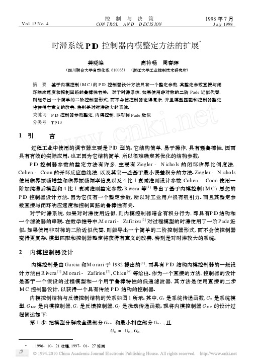
ZN : K c = 0. 91; T i = 2. 75; T d = 0. 68。CC: K c = 0. 91; T i = 3. 03; T d = 0. 53。
图 3 P ID 控制器整定公式比较 (Η= 0. 2) 图 4 P ID 控制器整定公式比较 (Η= 2)
根据图 3 和图 4 的比较结果, 对于一阶加时滞系统采用 P ID 控制器, 使用本文提出的参数 整定方法, 其优越性是明显的。
摘 要 基于内模控制 ( IM C) 的 P ID 控制器设计方法只有一个整定参数, 其整定参数直接与闭 环响应速度和控制回路的鲁棒性有关。 对于时滞系统, 如果使用非对称的二阶 Pade 近似代替, 则能导出一个简单的二阶控制器形式, 而不会使控制器变得复杂, 并且模型匹配和控制器整定 将获得有意义的改善, 特别是对时滞较大的系统。 关键词 P ID 控制器参数整定, 内模控制, 非对称 Pade 近似 分类号 T P13
数无量纲时滞时间; Κ Η则是决定闭环系Η T 和N 之间的关系, 可以图形的方式给出, 如图 2 所示。其中,
噪声滤波器系数N 取 3, 5 和 10。
通过方程 (6) 和图 2 可以得到以下几点: 1) 当 Η T → ∞ 时, Κ Η= Χ2 ∆= 0. 3225; 2) 当N
1998年
关于扩展内模整定方法, 可以得到如下几点结论: 1) 对于一阶加纯滞后系统, 不需要选择滤波器参数
Κ, 而是通过给定的 N 值由方程 (6) 给出。对于不同的系 统或不同的控制要求, 可考虑适当地修正参数 Χ1, Χ2 和 ∆。
2) 由方程 (4) 和 (5) 看到, 对于一阶加纯滞后系统, 扩展内模整定方法设计的 P ID 控制器无需前置滤波器。
基于PAC的时滞系统二自由度模糊内模控制的开题报告
基于PAC的时滞系统二自由度模糊内模控制的开题
报告
一、研究背景
随着现代科学技术的快速发展,控制系统的研究也不断深入。
时滞系统是一种重要的控制对象,它具有时间上的滞后特性,会对系统的稳定性和性能产生影响。
因此,对时滞系统的研究一直是控制领域的热点之一。
近年来,随着模糊控制理论的不断发展,其已被广泛应用于各类控制系统中。
在时滞系统控制中,常使用内模控制策略进行处理,它可以通过有效的状态反馈来控制时滞系统的动态特性。
二自由度控制结构是一种常用的内模控制策略,通过控制器的参数设计和系统参数的匹配,可以实现对时滞系统的稳定和性能指标的优化。
二、研究目的
本研究旨在探究基于PAC的时滞系统二自由度模糊内模控制方法,提出一种高效、有效的时滞系统控制方案,优化系统的稳定性和控制性能。
三、研究内容
1.时滞系统的特性分析及控制方法研究
2.模糊控制理论的原理及应用
3.内模控制方法的原理及应用
4.二自由度控制结构的设计方法
5.基于PAC的时滞系统二自由度模糊内模控制策略的研究和仿真分析
四、研究意义
本研究提出的基于PAC的时滞系统二自由度模糊内模控制策略,可以提高时滞系统的稳定性、响应速度以及控制精度。
同时,该控制策略还可以减少系统的计算复杂度,提高系统的实际应用性能。
因此,该研究对于推动时滞系统的控制理论以及相关应用有着重要的意义。
大时滞过程控制器设计与仿真
大时滞过程控制器设计与仿真摘要:针对工业过程中广泛存在的大时滞过程。
文中具体研究了设计了一种简单实用的双控制器设计方案,给出了具体的参数整定方法。
该方案含两个独立的控制器,即跟踪控制器和扰动控制器,使设定值响应得以与扰动响应分离,从而可同时获得良好的设定值跟踪性能和抗干扰能力,同时系统的鲁棒性也比现有控制方案大为增加,进一步显示了双控制器优越的性能。
关键词:时滞,过程控制,Smith预估器,双控制器Controller design and Simulation for large time delay processYusufu river. According to tie.Xinjiang Bayinguoleng occupation Tec Department of Textile EngineeringAbstract: the industrial process exists widely in the process with large time delay. This paper studies the design of a simple and practical controller design, given a specific parameter setting method. The programme contains two independent controller, namely tracking controller and disturbance controller, so that the response to a setpoint to perturbations in response to separation, which can also get a good set point tracking and anti-interference ability, at the same time, the robustness of the system is better than the existing control schemes to increase, further shows the dual controller of superior performance.Key words : delay, process control, Smith predictor, double controller1.引言工业生产的大规模化使工业过程变得更为复杂,大时滞、不确定性、严重非线性、时变性对工业过程控制系统的设计提出了更高的要求[1],因此,这需要更高级、更快速、更可靠、更有效的控制方法。
时滞多变量内模控制方法的研究的开题报告
时滞多变量内模控制方法的研究的开题报告一、选题背景内模控制技术已成为现代控制领域的重要研究方向之一,内模控制技术可以在保证控制系统动态性能的前提下,消除传统PID控制器存在的欠采样、模型精度差等缺陷,从而可以实现更优化的控制效果。
然而,时滞多变量内模控制问题一直是控制理论中的难点和热点问题之一,尤其是在复杂的控制环境中,时滞问题更加复杂,因此如何在时滞多变量情况下有效应用内模控制技术,已成为当前控制领域的研究重心之一。
二、研究内容本文拟从时滞多变量内模控制的角度,以非线性系统为例,研究其控制策略。
具体研究内容包括:(1)构建时滞多变量内模控制系统的数学模型。
(2)设计基于内模控制的时滞多变量控制器,采用新型非线性自适应控制技术,考虑系统不确定性和扰动问题,使得系统在具有时滞和多变量的情况下能够保持良好的鲁棒性和控制性能。
(3)进行仿真实验以验证所提出的时滞多变量内模控制方法的有效性和性能。
三、研究意义该研究可以为时滞多变量控制问题提供一种新的解决思路,为内模控制技术的发展提供一种新的研究方向。
并且,本研究所得到的控制器的性能和鲁棒性将有望在实际工程应用中发挥重要作用,为工程实践提供一种有效的控制方案。
四、研究方法本文主要采用数学建模和仿真实验相结合的方法进行研究,主要的研究步骤包括:(1)建立时滞多变量内模控制系统的数学模型。
(2)设计时滞多变量内模控制器并在MATLAB中进行仿真实验。
(3)对仿真实验的结果进行分析和评估。
(4)不断优化控制系统,使其达到更优化的控制效果。
五、研究进度目前,已初步完成了系统的数学建模工作以及控制方案的初步设计,正在进行仿真实验的准备工作。
预计在6月底完成仿真实验,并进行数据分析和结果评估。
随后将进一步完善控制系统,以期达到更优的控制效果。
- 1、下载文档前请自行甄别文档内容的完整性,平台不提供额外的编辑、内容补充、找答案等附加服务。
- 2、"仅部分预览"的文档,不可在线预览部分如存在完整性等问题,可反馈申请退款(可完整预览的文档不适用该条件!)。
- 3、如文档侵犯您的权益,请联系客服反馈,我们会尽快为您处理(人工客服工作时间:9:00-18:30)。
定义 IM C 控制器为, GIM C ( s) = G~ -P 1 ( s ) f ( s),
其中: f =
1 (1+
器, 为滤波器常数, 是内模控制仅有
的设计参数; 指数 n应选择得足够大, 以保证 GIM C 是可以实现的。 由图 1得反馈控制器与内模控制器 的关系:
作者简介: 罗耿 ( 1981 - ), 男, 工程师, 主要研究方向: 检测技术与自动 化装置。 收稿日期: 2008- 06- 21( 8275)
文章编号: 1671- 1041( 2008) 06- 0060- 03
时滞系统的内模控制设计及应用
卢丽丽, 金秀章, 李向菊, 郭会霞
(华北电力大学 控制科学与控制工程学院, 保定 071003)
内模控制器的设 计通常采用以下步骤 [ 3] :
( 1) 模型分解
G~ P ( s ) = G~ P + ( s ) G~ P- ( s) 式中, G~ P+ ( s) 包含所有的时滞和右半平面零点 。G~ P- ( s) 是 具有最小相位特征的 传递函数。 ( 2) IM C控制器设计
在设计控制器时 , 需在最小相位 的G~ P- ( s) 上增加滤波 器, 以确保系统的稳定性 和鲁棒性。
得一阶加滞后过程的一 阶 P ade近似的 IM C-P ID 控制器参数整
定公式如下:
Tf = 2(
+
), KC =
2 K
+ (
T+
Tf ),
Ti =
2 + T - Tf, Td =
2(
2
T
- Tf
+ T - Tf )
( 6)
3. 2 二阶加滞后过程的 IM C - PID 控制器设计
二阶加滞后时间过程形如:
K ey w ords: interna lm ode l contro;l IMC-P ID; delay tmi e control system; f irst order Pade approxmi ation
60 E IC Vo.l 15 2008 No. 6
欢迎光临本刊网站 h ttp: / /www. e ic. com. cn
计算出反馈控制器, 然后 将反 馈控 制器 转化 成传 统的 P ID 结
构, 就得到 了基 于内 模控制 的 P ID 控 制器
IM C-P ID 控制
器。现对纯滞后采用一阶 Pade近似, 从而对一阶和二阶加纯滞
后过程导出了只需整定一个参数 的 IM C-P ID 控制器。
3. 1 一阶加滞后过程的 IM C - P ID 控制器设计
一阶加滞后时间过程形如: G~ P ( s) ,
=
K Ts +
1e- s,
1- s
对 e- s 采用一阶 P ade近似 e- s =
2,
( 2)
1+ 2 s
则内模控制器
GIM C ( s )
=
K
T (
s+ s+
1 1
, )
( 3)
反馈控制器 GC ( s) =
Ts + 1
K ( s + 1) ( 1 -
递函数; G~ P是过程模型的传递函数; Gd 是 扰动通道 传递函 数, GIM C 是内模控制器, GC 是反馈控制器。
图 1 内模控制结构框图 2. 2 内模控制的主要性质
内模控制具有下 述 3个基本性质:
性质 1: 对偶 稳定性。当模型匹配时, 内模控制系 统的闭环 稳定性取决于前向通 道各个传递函数的稳定性。
e- s
, )
( 4)
s+ 1
而实际反馈控制器 GC ( P ID ) 可采用以下形式:
GC ( PID )
=
KC
(
1+
1 Tis
+
Tds Tf s +
1),
( 5)
式 ( 5) 中: KC、T i 和 Td 分别为控制器的放 大倍数、积分时
间和微分时间, Tf 取 T d 的某一倍数。
将式 ( 2) 代入式 ( 4) , 作必要简化处理后与式 ( 5) 比较, 可
{ K eyV a lue = 3; } else K eyV a lue = 4; } return K eyV a lue; }
4 结束语
本文所采用 的按 键扫 描识 别方 案性 能稳 定, 在需 要 时还 可对其进行扩展, 但经实验测试, 还存在不 足之处, 在按键数量 达到三十个以上时, 会出现准确性降低的现象。主要原因是由 电阻值误差引起, 因 此在 实 际应 用中 应尽 量选 用高 精度 的电 阻, 同时按键数量保持在 30个以下。
采用 C语言编写的 A /D 转换 码获取函数和键值获取函数 如下, 在主程 序中可随 需要进行调 用, 经 实际测试, 效果良 好, 按键扫描准确无误。 uns igned int G etADCode( unsigned char ADC0) / /获取 A /D 转换 码函数
{ uns igned char ;i
ADCSRA | = ( 1 < < AD IF ); / /清除标志位 ADCode = ADCode + ADC; }
re turn ADCode; } uns igned char G etK eyV alue( vo id) / /获取键 值函数 {
unsigned cha r K eyV alue = N okey; / /键值变量 unsigned int K eyADCode = 0; / /按键 ADC 码变量 K eyADCode = G etADCode( ADC _0); if ( K eyADCode < 995) / /有按键被按下 时
应用实 例
下的按键键 值。 图中 电 容 C1 用 于消 除 抖动 和 干 扰信 号 [ 3] 。 用该方法对键盘状态 进行扫描成本低、电路布线简单。
3 软件设计
用该方法扫描识 别按键过 程中, 软件设 计显得 尤为重 要, 在电阻阻值精确 的条 件下 , 对按 键动 作产 生的 电压 变化 范围 的判断应非 常准 确, 否则 会引 起扫 描出 错。在 综合 考虑 扫描 精度 和单片 机 I /O 口保 护的情 况下, 选 定 R 0 为 10 k 。 R 1、 R 2、R 3等的阻值由按键数量决定。 程序运行时, 首先将 ADC0引 脚的 电压值 转换 为数字 量, 然后 将其与特定 范围 值进 行比 较, 即可 得出 所按 按键 的键 值。考 虑到电阻阻值及 A /D 转换的 误差, 程 序中的 最大 A /D 转换码 值应比 1024稍小, 以增强系统的稳定性和准确性。
参考文献
[ 1 ] 丁化成, 耿德根, 李君凯. AVR 单片机应用设计. 北京: 北京航 空航天大学出版社, 2002.
[ 2 ] 马潮. A VR 单片机嵌入 式系统 原理与 应用实 践. 北京: 北京 航空航天大学出版社, 2007.
[ 3 ] 刘宗曦. 串联式键盘原理与应用. 辽宁 师范学院学报, 2003, 5 ( 4 ) : 83- 85.
uns igned int ADCode = 0; ADM UX = _BV ( REFS0) | ADC0; / /设置参考电压 for ( i= 0; i< 4; i+ + ) {
ADCSRA | = ( 1 < ADCSRA | = ( 1 < adc _ isr ( vo id) ); / /等待 ADC转换结束中断
G~ P + ( s)
=
K
e- s,
(T1s + 1) (T2s + 1)
按上述 步 骤 可得, 二 阶 加 滞后 过 程的 一 阶 P ade 近似 的
仪器仪表用户
{ D elay_m s( 10); / /延时 10ms的消抖处理 K eyADCode = G etADCode( ADC _0) ; if ( K eyA DCode < 683) / /获取键值 { K eyV a lue = 1; } else if ( K eyADCode < 388) { K eyV a lue = 2; } else if ( K eyADCode < 128)
关键词: 内模控制; IM C-PID; 时滞系统; 一阶 Pade近似 中图分类号: TP273 文献标识码: B
The design and application of in ternalm odel con trol to tim e delay con trol system
LU L -i l,i JI N X iu-zhang, L I X iang- ju, GUO H u -i xia
GC ( s ) =
GIM C ( s) 1 - GIM C ( s) G~ P+ ( s)
( 1)
欢迎订阅 欢迎撰稿 欢迎发布产品广告信息
应用实例
3 基于 IM C 的 P ID 控制器设计
R ive ra等首先提 出了 IM C-P ID 控制 器的设 计问题 [ 4、5] 。先
按照内模控制器设计的两步法 设计出内模 控制器, 再按 式 ( 1)
摘要: 基于内模控制理论, 针对时滞控制系统的纯滞后 环节, 采用一阶 Pade近 似, 设计了 结构简单, 且只有一 个参数需 要整定的 IM C-PID 控 制器。结果表明: 该控制器可获得相当于 内模控制 器良好的 控制性能 和鲁棒性, 又可充 分利用成熟的 P ID 控制 器, 因而 具有良好的位置 跟随 特性。
性质 2: 理 想 控 制 器 特 性。若 过程 稳 定 且 模 型 匹 确, 且
