LM304中文资料
304不锈钢的原理及应用细节

304不锈钢的原理及应用细节1. 304不锈钢的原理304不锈钢是一种通用的不锈钢材料,其主要成分为铬、镍以及小量的碳和铁。
由于其含有18%的铬和8%的镍,304不锈钢具有良好的耐腐蚀性能和机械性能。
304不锈钢的耐腐蚀性能来源于其中的铬元素。
铬能与氧气反应形成一种稳定的铬氧化物膜,这种膜能够阻止进一步的氧气渗透,从而防止金属的腐蚀。
镍在不锈钢中的作用主要是增加其机械性能和韧性。
除了铬和镍,304不锈钢还含有少量的碳,以提高材料的硬度。
此外,铁是304不锈钢的主要基础元素,它使得该材料具有良好的可塑性和可焊性。
2. 304不锈钢的应用细节2.1. 建筑领域•外部建筑装饰:由于304不锈钢具有美观且耐腐蚀的特性,它被广泛应用于建筑领域的外立面、屋顶和立柱等部位。
此外,304不锈钢还可用于室内装饰,如扶手、楼梯和栏杆等。
•建筑结构:304不锈钢常用于制造建筑领域的结构框架、支撑和连接件等。
其高强度和良好的耐腐蚀性能使得它成为一种可靠和耐用的材料。
•建筑设备:在建筑领域,304不锈钢常用于制造水池、水龙头、暖气片等设备。
由于其耐腐蚀性能,它能够在长期暴露于水环境中保持其美观和功能。
2.2. 化工领域•储罐和管道:304不锈钢在化学工业中被广泛用于制造储罐和管道。
由于其良好的耐腐蚀性能和耐高温性能,它可用于存储和输送各种化学物质。
•传热设备:304不锈钢的高导热性使得它成为化工领域中传热设备的理想选择。
例如,它可用于制造换热器、冷凝器和蒸发器等设备。
2.3. 食品加工领域•餐具器皿:304不锈钢在食品加工领域中用于制造餐具器皿,如刀具、叉子、勺子和碗等。
由于其耐腐蚀性和安全性能,它不会对食物产生不良影响。
•食品处理设备:304不锈钢用于制造食品加工设备,如食品储存罐、搅拌机和压榨机等。
它对食品的耐腐蚀性和卫生性能使其成为食品行业的首选材料。
2.4. 医疗领域•医疗器械:304不锈钢广泛应用于制造各种医疗器械,如手术器械、注射器和牙科工具等。
304不锈钢性能成分
304是一种通用性的不锈钢,它广泛地用于制作要求良好综合性能(耐腐蚀和成型性)的设备和机件。
301不锈钢在形变时呈现出明显的加工硬化现象,被用于要求较高强度的各种场合。
302不锈钢实质上就是含碳量更高的304不锈钢的变种,通过冷轧可使其获得较高的强度。
302B是一种含硅量较高的不锈钢,它具有较高的抗高温氧化性能。
303和303Se是分别含有硫和硒的易切削不锈钢,用于主要要求易切削和表面光洁度高的场合。
303Se不锈钢也用于制作需要热镦的机件,因为在这类条件下,这种不锈钢具有良好的可热加工性。
304L是碳含量较低的304不锈钢的变种,用于需要焊接的场合。
较低的碳含量使得在靠近焊缝的热影响区中所析出的碳化物减至最少,而碳化物的析出可能导致不锈钢在某些环境中产生晶间腐蚀(焊接侵蚀)。
304N是一种含氮的不锈钢,加氮是为了提高钢的强度。
305和384不锈钢含有较高的镍,其加工硬化率低,适用于对冷成型性要求高的各种场合。
308不锈钢用于制作焊条。
309、310、314及330不锈钢的镍、铬含量都比较高,为的是提高钢在高温下的抗氧化性能和蠕变强度。
而30S5和310S乃是309和310不锈钢的变种,所不同者只是碳含量较低,为的是使焊缝附近所析出的碳化物减至最少。
330不锈钢有着特别高的抗渗碳能力和抗热震性.316和317型不锈钢含有铝,因而在海洋和化学工业环境中的抗点腐蚀能力大大地优于304不锈钢。
其中,316型不锈钢由变种包括低碳不锈钢316L、含氮的高强度不锈钢316N以及合硫量较高的易切削不锈钢316F。
321、347及348是分别以钛,铌加钽、铌稳定化的不锈钢,适宜作高温下使用的焊接构件。
348是一种适用于核动力工业的不锈钢,对钽和钻的合量有着一定的限制。
碳元素在不锈钢中起什么作用碳是不锈钢中仅次于铬的第二号常用元素,不锈钢的组织和性能在很大程度上取决于碳含量及其分布状态。
碳是稳定奥氏体元素,它对奥氏体的稳定作用很强烈,约为镍的30倍。
304不锈钢基本简介
概述简单的说SUS304就是304不锈钢。
SUS是日本材料标准,304不锈钢是按照美国ASTM标准生产出来的不锈钢的一个牌号。
304相当于我国的0Cr19Ni9 (0Cr18Ni9)不锈钢,日本也引用了美国的叫法,称其为:SUS304由于含有较高的镍且在室温下呈奥氏体单相组织,所以它与Cr13不锈钢相比具有高的耐蚀性,在低温、室温及高温下均有较高的塑归和韧性,以及较好的冷作成型和焊接性。
但室温下的强度较低,晶间腐蚀及应力腐蚀倾向较大,切削加工性较差。
奥氏体在加热时无相变,因此不能通过热处理强化。
只能以提高钢的耐腐蚀性能进行热处理:用途304不锈钢以其良好的耐热性,而被广泛应用于制作耐腐蚀和成型性的设备和机件。
目前,304不锈钢已被广泛应用于食品、化工、原子能等工业设备以及装潢领域以及家庭用品、橱柜、室内管线、热水器、锅炉、浴缸、汽车配件、医疗器具、建材、化学、食品工业、农业、船舶部件。
[1]SUS304热处理规范:固熔1010~1150℃快冷。
金相组织:组织特征为奥氏体型。
SUS304即18/8不锈钢。
GB牌号为0Cr18Ni9(新标准 0cr19ni9)。
SUS304是日本JIS标准材料,是日本SUS系列奥氏体不锈钢。
相当于我国的0Cr18Ni9,美国的304特性具有良好的耐蚀性、耐热性、低温强度和机械性能,冲压弯曲等热加工性好,无热处理硬化现象,无磁性。
2热处理1)固熔处理其目的是使碳化物充分溶解并在常温下保留在奥氏体中,从而在常温下获单相奥氏体组织,使钢具有最高的耐腐蚀性能。
固溶处理的加热温度一般均较高,在1050-1100℃之间,并按含碳量的高低作适当调整。
由于18-8不锈钢导热性很差,不仅要通过预热后再进行淬火加热,而且在固溶处理(淬火加热)时的保温时间要长。
固溶处理时,要特别注意防止增碳。
因为增碳将会增加18-8钢的晶间腐蚀倾向。
冷却介质,一般采用清水。
固溶处理后的组织一般是单相奥氏体,但对含有钛、铌、钼的不锈钢,尤其当是铸件时,还含有少量的铁素体。
304不锈钢及其焊接简介

304不锈钢及其焊接简介一、概述304不锈钢 (0Cr18Ni9,AISI304,SUS304)是在最初发明的18-8型铬镍奥氏体不锈钢的基础上发展演变的钢种,是不锈钢的主体钢种,其产量占不锈钢总产量的30%以上。
它具有良好的冷、热加工性能、无磁性和好的低温性能;耐高温方面也比较好,一般使用温度极限小于650℃。
304型不锈钢具有优良的不锈耐腐蚀性能和较好的抗晶间腐蚀性能。
对氧化性酸,在实验中得出:浓度≤65%的沸腾温度以下的硝酸中,304不锈钢具有很强的抗腐蚀性。
对碱溶液及大部分有机酸和无机酸亦具有良好的耐腐蚀能力,以及大气、水、蒸汽中耐蚀性亦佳。
304不锈钢的良好性能,使其成为应用量最大、使用范围最广的不锈钢牌号,此钢适于制造深冲成型的部件以及输送腐蚀介质管道、容器,结构件等;亦可用于制造无磁、低温设备和部件。
但在易产生应力腐蚀环境和产生点蚀和缝隙腐蚀的条件下,在选用时应慎重。
二、用途家庭用品(1、2类餐具、橱柜、室内管线、热水器、锅炉、浴缸),汽车配件(风挡雨刷、消声器、模制品),医疗器具,建材,化学,食品工业,农业,船舶部件,核能、电力工业等。
三、化学成份及性能GB20878-2007,304、304L不锈钢化学成分带*号为耐热钢或可作耐热钢使用304不锈钢力学性能牌号固溶处理拉伸试验硬度试验屈服强度(MPa)抗拉强度/(MPa)伸长率(%)HBW HRB HV0Cr18Ni9 (304) 1010-1150℃快冷≥205≥520≥40≤187HB≤90≤20000Cr19Ni10 (304L) 1010-1150℃快冷≥177≥480≥40≤187HB≤90≤200四、焊接性能总体讲,该类不锈钢具有较好的可焊性。
但如焊接工艺及所处环境介质条件不当,易产生晶间腐蚀,焊件对焊接热裂纹敏感性较高,易析出脆性σ相;结构件易产生焊接变形。
在工艺适当的条件下,其焊接件有较好的综合性能,在碱液、大部分无机酸和有机酸及大气、水、蒸汽中均有好的耐蚀性,故获得了广范应用。
304不锈钢参数
304不锈钢参数1.化学成分:
-铬(Cr):16–18%
-镍(Ni):8–10.5%
-锰(Mn):2%
-硅(Si):1%
-磷(P):0.045%
-硫(S):0.03%
-碳(C):0.08%
2.物理性能:
- 密度:7.93 g/cm³
-熔点:1,400-1,450℃
-热导率:16.3W/m·K
-热膨胀系数:17.2μm/m·°C(0-100℃) 3.机械性能:
-抗拉强度:≥515MPa
-屈服强度:≥205MPa
-延伸率:≥40%
-硬度:≤201HBW
4.耐腐蚀性能:
-304不锈钢具有良好的耐腐蚀性,尤其对大多数酸性溶液和化学物质具有良好的抵抗能力。
-在腐蚀介质中,当铬的含量高于12%时,304不锈钢能够形成一层致密的钝化膜,防止进一步的腐蚀。
5.加工性能:
-304不锈钢具有优良的延展性和可塑性,能够通过冷加工和热加工进行成型。
-冷加工可以使304不锈钢获得更高的强度和硬度,但也会降低其耐腐蚀性。
-焊接性能良好,可采用常规的焊接方法进行焊接。
6.应用领域:
-304不锈钢广泛用于制造食品加工设备、医疗器械、化工装备等需要耐腐蚀性能的行业。
-在建筑业中,304不锈钢也常被用于制作门窗、扶手、护栏等装饰材料。
-由于其抗腐蚀性能,304不锈钢也经常用于制作石油、化工管道、船舶等领域的管道和容器。
综上所述,304不锈钢是一种常见的不锈钢材料,具有良好的耐腐蚀性能、高温强度和耐热性。
它的化学成分、物理性能、机械性能、耐腐蚀性能以及应用领域在不同行业中都有广泛的应用。
加工中心304 不锈钢光面参数

加工中心304 不锈钢光面参数英文版Machining Center 304 Stainless Steel Smooth Surface Parameters304 stainless steel, a common material in the machining industry, is widely used due to its corrosion resistance, ductility, and weldability. When working with this material on a machining center, achieving a smooth surface finish is crucial to ensure the quality of the final product. Here are some key parameters to consider when machining 304 stainless steel to achieve a smooth surface:Tool Material Selection: When machining 304 stainless steel, it's essential to choose a tool material that can withstand the high temperatures and wear resistance required. Carbide tools coated with titanium nitride (TiN) or aluminum titanium nitride (AlTiN) are commonly used for this purpose.Cutting Speed: The cutting speed plays a vital role in achieving a smooth surface. Lower cutting speeds can help reduce friction and heat generation, resulting in a finer surface finish. However, it's crucial to avoid extremely low speeds as they can lead to increased tool wear.Feed Rate: The feed rate determines the speed at which the tool moves across the workpiece. Higher feed rates can promote a smoother surface by reducing the time the tool spends in contact with the material. However, excessive feed rates can lead to tool wear and poor surface quality.Depth of Cut: The depth of cut affects the amount of material removed during each pass of the tool. Shallower depths of cut can lead to a smoother surface by reducing the amount of force exerted on the tool. However, this may require multiple passes to achieve the desired material removal.Coolant Usage: The application of coolant during machining can help reduce heat generation and improve surface finish.Water-based coolants are commonly used for 304 stainless steel, as they provide effective cooling and lubrication.Post-Machining Processes: Achieving a smooth surface may also require additional processes such as polishing or buffing after machining. These processes can remove any residual roughness or marks left by the machining process.By carefully selecting the right tool material, adjusting cutting parameters, and implementing post-machining processes, it is possible to achieve a smooth surface finish when machining 304 stainless steel on a machining center.中文版加工中心304不锈钢光面参数304不锈钢是加工行业中常见的材料,因其耐腐蚀、延展性和可焊性而被广泛使用。
304不锈钢规格参数

304不锈钢规格参数
304不锈钢是一种广泛使用的金属材料,其规格参数包括以下几个方面:
1. 化学成分:304不锈钢是一种奥氏体不锈钢,含有18%的铬(Cr)和8%的镍(Ni)。
它还含有少量的碳、硅、锰、硫和磷等元素。
2. 机械性能:304不锈钢具有良好的机械性能,包括高强度、良好的韧性和优良的加工性能。
其抗拉强度为520MPa,屈服强度为205MPa,延伸率为40%。
3. 耐腐蚀性:由于含有铬和镍等元素,304不锈钢具有良好的耐腐蚀性,能够在许多腐蚀性环境中使用。
4. 表面处理:304不锈钢可以进行抛光、喷砂、拉丝等多种表面处理,以增加其美观度和耐腐蚀性。
5. 应用领域:304不锈钢被广泛应用于建筑、家电、汽车、食品加工等领域,如厨房用具、热水器、洗衣机、汽车零部件等。
总之,304不锈钢是一种优秀的金属材料,具有优良的化学成分、机械性能、耐腐蚀性和表面处理性能,被广泛应用于各个领域。
304不锈钢的工作范围
304不锈钢的工作范围304不锈钢是一种常用的不锈钢材料,具有广泛的工作范围。
下面将从不锈钢的化学成分、物理性能以及应用领域等方面进行详细介绍。
304不锈钢是由18%的铬和8%的镍以及少量的碳、锰等元素组成的。
其中铬是不锈钢的主要合金元素,能够形成致密的氧化膜保护不锈钢表面不受腐蚀。
镍的添加可以提高不锈钢的耐腐蚀性和耐高温性能。
此外,304不锈钢还含有一定量的碳和锰,以增加其强度和耐磨性。
304不锈钢具有优异的物理性能。
首先,它具有良好的耐高温性能,可在高温环境下长时间工作。
其次,该材料具有良好的耐腐蚀性,能够抵御大部分酸性和碱性介质的侵蚀。
此外,304不锈钢还具有优异的机械性能,具有较高的屈服强度和抗拉强度,适用于承受较大载荷的工作环境。
此外,该材料还具有良好的加工性能,可以通过冷加工、热加工等方法制成各种形状的零件。
由于304不锈钢具有良好的性能,因此在许多领域得到了广泛的应用。
首先,在建筑领域,304不锈钢常用于制作门窗、栏杆、楼梯扶手等装饰建材。
由于其外观美观、耐腐蚀性好,可以延长使用寿命,因此受到了广大用户的青睐。
其次,在化工领域,304不锈钢常用于制作储罐、管道等设备。
由于其耐腐蚀性好,能够承受酸碱介质的侵蚀,因此在化工生产中得到了广泛应用。
此外,在食品加工领域,304不锈钢也被广泛应用于制作食品设备,如食品加工机械、食品储存容器等。
由于其不会对食品产生任何污染,因此可以保证食品的质量和安全。
此外,304不锈钢还常用于制作医疗器械、家居用品等。
304不锈钢具有广泛的工作范围。
其优异的物理性能和耐腐蚀性使其在建筑、化工、食品加工等领域得到了广泛应用。
随着科学技术的发展,不锈钢材料将在更多的领域中得到应用,并发挥出更大的作用。
304不锈钢管

基础信息304化学牌号为0Cr18Ni9 含铬17%,含镍8%。
304是得到最广泛应用的不锈钢、耐热钢。
用于食品生产设备、普通化工设备、核能等. 304不锈钢化学成份规格C Si Mn P S Cr Ni(镍)Mo不锈钢SUS304密度为7.93 克/厘米3SUS304化学成分≤0.08 ≤1.00 ≤2.00 ≤0.05 ≤0.03 18.00-20.00 8.00~10.50 -产品标准对于304不锈钢来说是非常重要的一个参数,直接决定着它的抗腐蚀能力,也决定着它的价值。
304中最为重要的元素是Ni,Cr,但是又不仅限于这两个元素。
具体的要求由产品标准规定。
行业常见判定情况认为只要Ni含量大于8%,Cr含量大于18%,就可以认为是304不锈钢。
这也是为什么业内会把这类不锈钢叫做18/8不锈钢的原因。
其实不然,相关的产品标准对304有着非常清楚的规定,而这些产品标准针对不同形状的不锈钢又有一些差异。
下面是一些常见的产品标准与测试。
304不锈钢判定要想确定一个材料是不是304不锈钢,必须满足产品标准中每一个元素的要求,只要有一个不符合,就不能叫做304不锈钢。
1、ASTM A276(Standard Specification for Stainless Steel Bars棒材and Shapes型材)304 C Mn P S Si Cr Ni要求,% 0.08 2.00 0.045 0.030 1.00 18.0–20.0 8.0-11.02、ASTM A240(Chromium and Chromium-Nickel Stainless Steel Plate板材,Sheet片材, and Strip带材for Pressure essels and for General Applications)304 C Mn P S Si Cr Ni N要求,% 0.07 2.00 0.045 0.030 0.075 17.5–19.5 8.0–10.5 0.103、JIS G4305(cold-rolled 冷轧stainless steel plate板材, sheet片材and strip带材)SUS 304 C Mn P S Si Cr Ni要求,% 0.08 2.00 0.045 0.030 1.00 18.0–20.0 8.0-10.54、JIS G4303 (Stainless steel bars不锈钢棒)SUS 304 C Mn P S Si Cr Ni要求,% 0.08 2.00 0.045 0.030 1.00 18.0–20.0 8.0-10.5以上四个标准只是常见的几个标准,其实ASTM和JIS中有提到304的不止这几个标准。
304不锈钢参数
304不锈钢参数
1.化学成分:
304不锈钢的化学成分包括:碳(C)的含量≤0.08%,硅(Si)的含量≤1.00%,锰(Mn)的含量≤2.00%,磷(P)的含量≤0.045%,硫(S)的含量≤0.030%,铬(Cr)的含量为18.00-20.00%,镍(Ni)的含量为8.00-10.50%。
2.机械性能:
3.物理性能:
密度:7.93 g/cm³
热膨胀系数:17.2×10^(-6)/℃
导热系数:16.3W/m·K
电阻率:0.73 Ω·mm²/m
4.耐腐蚀性:
5.焊接性能:
304不锈钢具有良好的焊接性能,可以采用常见的焊接方法,如电弧焊、惰性气体保护焊和电阻焊等。
然而,在高温环境下,它可能会产生析出碳化物的倾向,导致晶间腐蚀的发生。
因此,在高温焊接时需要采取相应的预防措施。
6.应用领域:
7.维护保养:
为了保持304不锈钢材料的美观和耐蚀性,需要定期清洁和保养。
常见的清洁方法包括:用中性清洁剂和软布擦拭表面、避免使用含氨、盐酸和硫酸的清洁剂、定期进行清洗和去污。
总结起来,304不锈钢具有优良的耐腐蚀性、机械性能和焊接性能,是一种常用的不锈钢材料。
它的化学成分包括碳、硅、锰、磷、硫、铬和镍。
在各个领域有广泛的应用,并需要进行定期的清洁和维护,以保持其性能和外观。
LM3046M中文资料
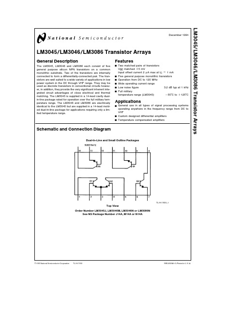
TL H 7950LM3045 LM3046 LM3086 Transistor ArraysDecember1994LM3045 LM3046 LM3086Transistor ArraysGeneral DescriptionThe LM3045 LM3046and LM3086each consist of fivegeneral purpose silicon NPN transistors on a commonmonolithic substrate Two of the transistors are internallyconnected to form a differentially-connected pair The tran-sistors are well suited to a wide variety of applications in lowpower system in the DC through VHF range They may beused as discrete transistors in conventional circuits howev-er in addition they provide the very significant inherent inte-grated circuit advantages of close electrical and thermalmatching The LM3045is supplied in a14-lead cavity dual-in-line package rated for operation over the full military tem-perature range The LM3046and LM3086are electricallyidentical to the LM3045but are supplied in a14-lead mold-ed dual-in-line package for applications requiring only a lim-ited temperature rangeFeaturesY Two matched pairs of transistorsV BE matched g5mVInput offset current2m A max at I C e1mAY Five general purpose monolithic transistorsY Operation from DC to120MHzY Wide operating current rangeY Low noise figure3 2dB typ at1kHzY Full militarytemperature range(LM3045)b55 C to a125 CApplicationsY General use in all types of signal processing systemsoperating anywhere in the frequency range from DC toVHFY Custom designed differential amplifiersY Temperature compensated amplifiersSchematic and Connection DiagramDual-In-Line and Small Outline PackagesTL H 7950–1Top ViewOrder Number LM3045J LM3046M LM3046N or LM3086NSee NS Package Number J14A M14A or N14AC1995National Semiconductor Corporation RRD-B30M115 Printed in U S AAbsolute Maximum Ratings (T A e 25 C)If Military Aerospace specified devices are required please contact the National Semiconductor Sales Office Distributors for availability and specificationsLM3045LM3046 LM3086Each Total Each Total Units Transistor Package Transistor PackagePower Dissipation T A e 25 C 300750300750mW T A e 25 C to 55 C 300750mW T A l 55 C Derate at 6 67mW C T A e 25 C to 75 C 300750mW T A l 75 C Derate at 8mW C Collector to Emitter Voltage V CEO 1515V Collector to Base Voltage V CBO 2020V Collector to Substrate Voltage V CIO (Note 1)2020VEmitter to Base Voltage V EBO55V Collector Current I C5050mA Operating Temperature Rangeb 55 C to a 125 C b 40 C to a 85 C Storage Temperature Rangeb 65 C to a 150 C b 65 C to a 85 C Soldering InformationDual-In-Line Package Soldering (10Sec )260 C260 CSmall Outline Package Vapor Phase (60Seconds)215 C Infrared (15Seconds)220 CSee AN-450‘‘Surface Mounting Methods and Their Effect on Product Reliability’’for other methods of soldering surface mount devicesElectrical Characteristics (T A e 25 C unless otherwise specified)LimitsLimits ParameterConditionsLM3045 LM3046LM3086UnitsMin Typ MaxMin Typ MaxCollector to Base Breakdown Voltage (V (BR)CBO )I C e 10m A I E e 020602060V Collector to Emitter Breakdown Voltage (V (BR)CEO )I C e 1mA I B e 015241524V Collector to Substrate Breakdown I C e 10m A I CI e 020602060V Voltage (V (BR)CIO )Emitter to Base Breakdown Voltage (V (BR)EBO )I E 10m A I C e 05757V Collector Cutoff Current (I CBO )V CB e 10V I E e 00 002400 002100nA Collector Cutoff Current (I CEO )V CE e 10V I B e 00 55m A Static Forward Current Transfer V CE e 3VI C e 10mA 100100Ratio (Static Beta)(h FE )I C e 1mA 4010040100I C e 10m A5454Input Offset Current for Matched V CE e 3V I C e 1mA 0 32m A Pair Q 1and Q 2l I O1b I IO2l Base to Emitter Voltage (V BE )V CE e 3VI E e 1mA 0 7150 715V I E e 10mA0 8000 800Magnitude of Input Offset Voltage for V CE e 3V I C e 1mA 0 455mV Differential Pair l V BE1b V BE2lMagnitude of Input Offset Voltage for Isolated V CE e 3V I C e 1mATransistors l V BE3b V BE4l l V BE4b V BE5l 0 455mVl V BE5b V BE3lTemperature Coefficient of Base to V CE e 3V I C e 1mAEmitter VoltageD V BED TJb 1 9b 1 9mV C Collector to Emitter Saturation Voltage (V CE(SAT))I B e 1mA I C e 10mA 0 230 23V Temperature Coefficient of V CE e 3V I C e 1mAInput Offset VoltageD V 10D TJ1 1m V CNote 1 The collector of each transistor of the LM3045 LM3046 and LM3086is isolated from the substrate by an integral diode The substrate (terminal 13)must be connected to the most negative point in the external circuit to maintain isolation between transistors and to provide for normal transistor action2Electrical Characteristics (Continued)ParameterConditions MinTyp MaxUnits Low Frequency Noise Figure (NF)f e 1kHz V CE e 3V 3 25dBI C e 100m A R S e 1k X LOW FREQUENCY SMALL SIGNAL EQUIVALENT CIRCUIT CHARACTERISTICS Forward Current Transfer Ratio (h fe )f e 1kHz V CE e 3V 110(LM3045 LM3046)I C e 1mA(LM3086)Short Circuit Input Impednace (h ie )3 5k X Open Circuit Output Impedance (h oe )15 6m mhoOpen Circuit Reverse Voltage Transfer Ratio (h re )1 8x 10b 4ADMITTANCE CHARACTERISTICS Forward Transfer Admittance (Y fe )f e 1MHz V CE e 3V 31b j 1 5Input Admittance (Y ie )I C e 1mA0 3a J 0 04Output Admittance (Y oe )0 001a j 0 03Reverse Transfer Admittance (Y re )See Curve Gain Bandwidth Product (f T )V CE e 3V I C e 3mA 300550Emitter to Base Capacitance (C EB )V EB e 3V I E e 00 6pF Collector to Base Capacitance (C CB )V CB e 3V I C e 00 58pF Collector to Substrate Capacitance (C CI )V CS e 3V I C e 02 8pFTypical Performance CharacteristicsTemperature for Each Cutoff Current vs Ambient Typical Collector To Base TransistorTemperature for Each Cutoff Current vs Ambient Typical Collector To Emitter TransistorBeta Ratio for Transistors Q 1and Q 2vs Emitter CurrentCurrent-Transfer Ratio and Typical Static ForwardTL H 7950–2Q 1Q 2vs Collector Currentfor Matched Transistor Pair Typical Input Offset Current Offset Voltage for Differential Voltage Characteristic and Input Typical Static Base To Emitter Transistors vs Emitter CurrentPair and Paired IsolatedTL H 7950–33Typical Performance Characteristics(Continued)Each Transistor vs Ambient Voltage Characteristic for Typical Base To Emitter TemperaturePair and Paired Isolated Characteristics for Differential Typical Input Offset Voltage TemperatureTransistors vs Ambient Collector CurrentTypical Noise Figure vs TL H 7950–4Typical Normalized Forward Current Transfer Ratio Short Circuit Input ImpedanceOpen Circuit Output Impedance Collector Current Typical Noise Figure vs Collector CurrentTypical Noise Figure vs Collector CurrentVoltage Transfer Ratio vs and Open Circuit Reverse TL H 7950–5Admittance vs Frequency Typical Forward Transfer vs Frequency Typical Input Admittance vs FrequencyTypical Output Admittance TL H 7950–64Typical Performance Characteristics(Continued)Admittance vs FrequencyTypical Reverse Transfer Product vs Collector CurrentTypical Gain-BandwidthTL H 7950–7Physical Dimensions inches (millimeters)Ceramic Dual-In-Line Package (J)Order Number LM3045J NS Package Number J14A5L M 3045 L M 3046 L M 3086T r a n s i s t o r A r r a y sPhysical Dimensions inches (millimeters)(Continued)Molded Small Outline Package (M)Order Number LM3046M NS Package Number M14AMolded Dual-In-Line Package (N)Order Number LM3046N or LM3086NNS Package Number N14ALIFE SUPPORT POLICYNATIONAL’S PRODUCTS ARE NOT AUTHORIZED FOR USE AS CRITICAL COMPONENTS IN LIFE SUPPORT DEVICES OR SYSTEMS WITHOUT THE EXPRESS WRITTEN APPROVAL OF THE PRESIDENT OF NATIONAL SEMICONDUCTOR CORPORATION As used herein 1 Life support devices or systems are devices or 2 A critical component is any component of a life systems which (a)are intended for surgical implant support device or system whose failure to perform can into the body or (b)support or sustain life and whose be reasonably expected to cause the failure of the life failure to perform when properly used in accordance support device or system or to affect its safety or with instructions for use provided in the labeling can effectivenessbe reasonably expected to result in a significant injury to the userNational Semiconductor National Semiconductor National Semiconductor National Semiconductor CorporationEuropeHong Kong LtdJapan Ltd1111West Bardin RoadFax (a 49)0-180-530858613th Floor Straight Block Tel 81-043-299-2309。
304 不锈钢英文版参数
304 不锈钢英文版参数English:Stainless steel is a versatile material that is used in a wide range of industries and applications due to its excellent corrosion resistance, high strength, and attractive appearance. In terms of its mechanical properties, stainless steel typically has a tensile strength of MPa, a yield strength of MPa, and an elongation of 40-60%. Its hardness varies depending on the grade, with common grades like 304 and 316 having a Rockwell hardness of 70-90. Stainless steel also offers good thermal conductivity and low thermal expansion, making it suitable for high-temperature applications. Additionally, it has excellent formability, weldability, and machinability, allowing for various fabrication processes such as bending, welding, and machining. In terms of its chemical composition, stainless steel contains at least % chromium, which forms a thin oxide layer on the surface, providing its corrosion resistance. Other alloying elements such as nickel, molybdenum, and titanium may also be added to enhance specific properties. Furthermore, stainless steel is available in various grades, each with its own unique combination of properties and applications, ranging from austenitic stainless steelslike 304 and 316, to ferritic and martensitic stainless steels for different requirements.中文翻译:不锈钢是一种多用途材料,由于其优异的耐腐蚀性、高强度和吸引人的外观,在广泛的行业和应用中得到应用。
304美标标准

304美标标准摘要:1.304 美标标准的概述2.304 美标标准的具体参数3.304 美标标准的应用领域4.304 美标标准的优势和意义正文:一、304 美标标准的概述304 美标标准,即美国材料和试验协会标准(ASTM)中的一种不锈钢标准,主要用于规范和定义不锈钢的牌号、化学成分、力学性能、工艺性能等技术要求。
在不锈钢领域中,304 美标标准被广泛应用,尤其在石油、化工、医疗、食品等工业领域以及建筑装饰等领域有着举足轻重的地位。
二、304 美标标准的具体参数304 美标标准的具体参数主要包括以下三个方面:1.化学成分:304 美标标准的不锈钢主要由铁、铬、镍等元素组成,其化学成分比例分别为:碳(C)≤0.08%,锰(Mn)≤2.0%,硅(Si)≤1.0%,磷(P)≤0.045%,硫(S)≤0.03%,铬(Cr)17.0%-20.0%,镍(Ni)8.0%-11.0%。
2.力学性能:304 美标标准的不锈钢要求具备一定的强度、硬度、塑性、韧性等力学性能。
其拉伸强度(σb)需达到≥637MPa,屈服强度(σs)需达到≥373MPa,硬度(HB)需在130-210 之间,伸长率(δ5)需达到≥35%。
3.工艺性能:304 美标标准的不锈钢需具备良好的冷弯性能、焊接性能、冷拔性能等工艺性能,以满足各种加工和使用要求。
三、304 美标标准的应用领域304 美标标准的不锈钢因其良好的耐腐蚀性能、焊接性能、冷弯性能等优点,广泛应用于石油、化工、医疗、食品等工业领域,以及建筑装饰、家具制造、汽车制造等众多行业。
四、304 美标标准的优势和意义304 美标标准的不锈钢具有以下优势:1.良好的耐腐蚀性能:304 不锈钢含有17%-20% 的铬元素,具有较好的耐腐蚀性能,尤其在氧化性介质和弱酸性介质中表现更佳。
2.优异的焊接性能:304 不锈钢的镍含量较高,有助于提高焊接部位的韧性和塑性,使得焊接质量更佳。
3.良好的冷弯性能和冷拔性能:304 不锈钢的力学性能适中,便于冷弯和冷拔加工,满足各种加工和使用要求。
最新304不锈钢管资料课件PPT

• 2 焊接 • 304不锈钢管抑制焊接时的碳化物析出,可采用通用的方法进行焊接。手工电
弧焊,含碳0.04%-0.06%的薄截面尺寸的304不锈钢可采用奥002焊条,焊后 可不产生晶间腐蚀倾向,对于厚截面尺,要保持焊后的耐晶间腐蚀性能,需进 行焊后热处理,若不热处理,应改为304L不锈钢或稳定型奥氏体不锈钢。
• 304不锈钢管作为不锈耐热钢使用最广泛,食品用设备,一般化工设备, 原子能工业用设备。
• 304 不锈钢管是一种通用性的不锈钢管,它广泛地用于制作要求良好综合 性能(耐腐蚀和成型性)的设备和机件。
• 304不锈钢管是得到最广泛应用的不锈钢、耐热钢。用于食品生产设备、 昔通化工设备、核能等.
• 304不锈钢管化学成份 规格 C Si Mn P S Cr Ni(镍) Mo • SUS304 ≤0.08 ≤1.00 ≤2.00 ≤0.05 ≤0.03 18.00-20.00 8.25~10.50 • 从金相学角度分析,因为不锈钢含有铬而使表面形成很薄的铬膜,这个膜
•12.1 16.3 21.4
20 100 500
•线胀系数α/(10-6/℃) (在下列温度间/℃)
•0510~6892~3981~
0510.68 92.3982
•电阻率0.73 Ω·mm2·m-1
•熔点 1398~14GB/T14976-2012(流体输送用不锈钢无缝 钢管),GB/T14975-2012(结构用不锈钢无缝管)、 GB/T13296-91(锅炉、热交换器用不锈钢无缝钢管), 装饰用焊接不锈钢管(GB/T 18705-2002),建筑装 饰用不锈钢焊接管材(JG/T 3030-1995),均经过严 格的检测,符合国家标准的技术指标要求材质321/ 1Cr18Ni9Ti 304/0Cr18Ni9 310S /0Cr25Ni20 316L/00Cr17Ni14Mo2 301 304L
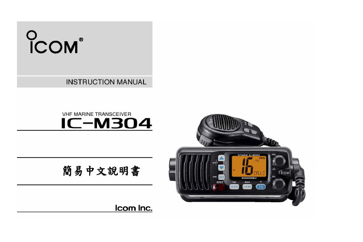
IC-M304
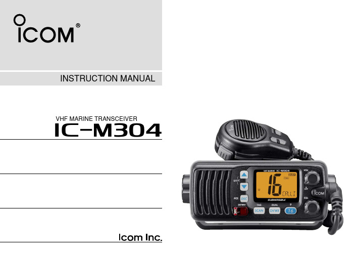
INSTRUCTION MANUALVHF MARINE TRANSCEIVERFOREWORDThank you for purchasing this Icom radio. The IC-M304 VHF MARINE TRANSCEIVER is designed and built with Icom’s stateof the art technology and craftsmanship. With proper care, this radio should provide you with years of trouble-free oper-ation.We hope you agree with Icom’s philosophy of “technology first.” Many hours of research and development went into the design of your IC-M304.D FEATURES❍Large 2-digit Channel with scrolling comment ❍New Force5Audio speaker❍Built-in DSC meets RTCM SC101 requirement ❍Submersible construction❍Favorite channel function❍AquaQuake water draining function IMPORTANTREAD ALL INSTRUCTIONS carefully and completely before using the transceiver.SAVE THIS INSTRUCTION MANUAL— This in-struction manual contains important operating instructions for the IC-M304.EXPLICIT DEFINITIONSCLEAN THE TRANSCEIVER AND MICROPHONE THOR-OUGHLY WITH FRESH WATER after exposure to water including salt water, otherwise, the keys and switches may become inoperable due to salt crystallization.Icom, Icom Inc. and the logo are registered trademarks of Icom Incor-porated (Japan) in the United States, the United Kingdom, Germany, France, Spain, Russia and/or other countries.FORCE5AUDIO logo is a registered trademark of Icom Incorporated (Japan) in the United States.iIN CASE OF EMERGENCYIf your vessel requires assistance, contact other vessels and the Coast Guard by sending a distress call on Channel 16. Or, transmit your distress call using digital selective calling on Channel 70.NOTEA WARNING STICKER is supplied with the transceiver.To comply with FCC regulations, this sticker must be affixed in such a location as to be readily seen from the operating con-trols of the radio as in the diagram below. Make sure the cho-sen location is clean and dry before applying the sticker. (p. 32)EXAMPLEWARNINGSTICKERiiRADIO OPERATOR WARNINGIcom requires the radio operator to meet theFCC Requirements for Radio Frequency Expo-sure. An omnidirectional antenna with gain notgreater than 9 dBi must be mounted a minimumof 5 meters (measured from the lowest point ofthe antenna) vertically above the main deck and all possible personnel. This is the minimum safe separation distance estimated to meet all RF exposure compliance re-quirements. This 5 meter distance is based on the FCC Safe Maximum Permissible Exposure (MPE) distance of 3 meters added to the height of an adult (2 meters) and is appropriate for all vessels.For watercraft without suitable structures, the antenna must be mounted so as to maintain a minimum of 1 meter vertically between the antenna, (measured from the lowest point of the antenna), to the heads of all persons AND all persons must stay outside of the 3 meter MPE radius.Do not transmit with radio and antenna when persons are within the MPE radius of the antenna, unless such persons (such as driver or radio operator) are shielded from antenna field by a grounded metallic barrier. The MPE Radius is the minimum distance from the antenna axis that person should maintain in order to avoid RF exposure higher than the allow-able MPE level set by FCC.FAILURE TO OBSERVE THESE LIM ITS M AY ALLOW THOSE WITHIN THE MPE RADIUS TO EXPERIENCE RF RADIATION ABSORPTION WHICH EXCEEDS THE FCC MAXIMUM PERMISSIBLE EXPOSURE (MPE) LIMIT.IT IS THE RESPONSIBILITY OF THE RADIO OPERATOR TO ENSURE THAT THE MAXIMUM PERMISSIBLE EXPO-SURE LIMITS ARE OBSERVED AT ALL TIMES DURING RADIO TRANSMISSION. THE RADIO OPERATOR IS TO ENSURE THAT NO BYSTANDERS COME WITHIN THE RADIUS OF THE MAXIMUM PERMISSIBLE EXPOSURE LIMITS.Determining MPE RadiusTHE M AXIM UM PERM ISSIBLE EXPOSURE (M PE) RA-DIUS HAS BEEN ESTIM ATED TO BE A RADIUS OF ABOUT 3M PER OET BULLETIN 65 OF THE FCC.THIS ESTIM ATE IS M ADE ASSUM ING THE M AXIM UM POWER OF THE RADIO AND ANTENNAS WITH A MAXI-MUM GAIN OF 9dBi ARE USED FOR A SHIP MOUNTED SYSTEM.iiiFOREWORD (i)IMPORTANT (i)EXPLICIT DEFINITIONS (i)IN CASE OF EMERGENCY (ii)NOTE (ii)RADIO OPERATOR WARNING (iii)TABLE OF CONTENTS (iv)PRECAUTIONS (v)1OPERATING RULES (1)2PANEL DESCRIPTION…………………………………………2–4I Front panel (2)I Microphone (3)I Function display (4)3BASIC OPERATION……………………………………………5–9I Channel selection (5)I Receiving and transmitting (7)I Call channel programming (8)I Channel comments (8)I Microphone lock function (9)I Display backlighting (9)I AquaQuake water draining function (9)4SCAN OPERATION…………………………………………10–11I Scan types (10)I Setting TAG channels (11)I Starting a scan (11)5DUALWATCH/TRI-WATCH (12)I Description (12)I Operation………………………………………………………126DSC OPERATION……………………………………………13–27I MMSI code programming (13)I MMSI code check (13)I DSC address ID (14)I Position indication (15)I Distress call (16)I Transmitting DSC calls (17)I Receiving DSC calls (24)7SET MODE……………………………………………………28–30I Set mode programming (28)I Set mode items (29)8CONNECTIONS AND MAINTENANCE……………………31–34I Connections (31)I Supplied accessories (32)I Antenna (32)I Fuse replacement (32)I Cleaning (32)I Mounting the transceiver (33)I Optional MB-92 attachment (33)I Optional MB-69 installation (34)9TROUBLESHOOTING (35)10CHANNEL LIST (36)11SPECIFICATIONS AND OPTIONS ………………………37–38I Specifications (37)I Options (38)12TEM PLATE (39)TABLE OF CONTENTSivPRECAUTIONSR WARNING! NEVER connect the transceiver to an AC outlet. This may pose a fire hazard or result in an electric shock.CAUTION:Changes or modifications to this device, not ex-pressly approved by Icom Inc., could void your authority to operate this device under FCC regulations.NEVER connect the transceiver to a power source of more than 16 V DC or use reverse polarity. This will ruin the trans-ceiver.NEVER cut the DC power cable between the DC plug and fuse holder. If an incorrect connection is made after cutting, the transceiver may be damaged.NEVER place the transceiver where normal operation of the vessel may be hindered or where it could cause bodily injury. KEEP the transceiver at least 3.3 ft (1 m) away from the ship’s navigation compass.DO NOT use or place the transceiver in areas with temper-atures below –4°F (–20°C) or above +140°F (+60°C) or, in areas subject to direct sunlight, such as the dashboard. AVOID the use of chemical agents such as benzine or al-cohol when cleaning, as they may damage the transceiver surfaces.BE CAREFUL!The transceiver rear panel will become hot when operating continuously for long periods.Place the transceiver in a secure place to avoid inadvertent use by children.BE CAREFUL! The transceiver (except cables) and hand microphone employ waterproof construction, which corre-sponds to I PX7 of the international standard I EC 60529 (2001). However, once the transceiver has been dropped, waterproofing cannot be guaranteed due to the fact that the case may be cracked, or the waterproof seal damaged, etc.v1 OPERATING RULESD PRIORITIES•Read all rules and regulations pertaining to priorities and keep an up-to-date copy handy. Safety and distress calls take priority over all others.•You must monitor Channel 16 when you are not operating on another channel.•False or fraudulent distress signals are prohibited and pun-ishable by law.D PRIVACY•Information overheard but not intended for you cannot law-fully be used in any way.•Indecent or profane language is prohibited.D RADIO LICENSES(1) SHIP STATION LICENSEYou must have a current radio station license before using the transceiver. It is unlawful to operate a ship station which is not licensed.Inquire through your dealer or the appropriate government agency for a Ship-Radiotelephone license application. This government-issued license states the call sign which is your craft’s identification for radio purposes.(2) OPERATOR’S LICENSEA Restricted Radiotelephone Operator Permit is the licensemost often held by small vessel radio operators when a radiois not required for safety purposes.The Restricted Radiotelephone Operator Permit must be posted or kept with the operator. Only a licensed radio opera-tor may operate a transceiver.However, non-licensed individuals may talk over a transceiverif a licensed operator starts, supervises, ends the call and makes the necessary log entries.Keep a copy of the current government rules and regulations handy.11PANEL DESCRIPTION 2I Front panelq CHANNEL UP/DOWN KEYS [Y]/[Z]•[U/I/C]➥Selects the operating channels, Set mode settings, etc.(pgs. 5, 6, 28)➥While pushing and holding [SCAN], push to adjust the brightness of the LCD and key backlight. (p. 9)➥Selects one of three channel groups in sequence when both keys are pushed. (p. 6)•U.S.A., International and Canadian channels are available.➥While turning power ON, push and hold both keys to ac-tivate the AquaQuake function. (p. 9)w POWER/VOLUME CONTROL[VOL](p. 7)Rotate to turn the transceiver power ON and OFF and ad-justs the audio level.e SQUELCH CONTROL[SQL](p. 7)Rotate to set the squelch threshold level.r CHANNEL16/CALL CHANNEL KEY[!6•9]➥Push to select Channel 16. (p. 5)➥Push and hold for 1 sec. to select call channel. (p. 5)•“CALL” appears when the call channel is selected.➥Push and hold for 3 sec. to enter call channel program-ming condition when the call channel is selected. (p. 8)➥While pushing and holding [CH/WX], push to enter the channel comments programming condition. (p. 8)➥Push to move the cursor forward. (p. 8)➥While turning power ON, push to enter Set mode. (p. 28) t CHANNEL/WEATHER CHANNEL KEY[CH/WX•DUAL]➥Selects and toggles the regular channel and weather channel when pushed momentarily. (p. 6)➥Push and hold for 1 sec. to start Dualwatch or Tri-watch.(p. 12)➥Push to stop Dualwatch or Tri-watch when either is acti-vated. (p. 12)➥Push to move the cursor backward. (p. 8)22 PANEL DESCRIPTIONy SCAN KEY[SCAN•TAG](p. 11)➥Push to start or stop the Normal or Priority scan.➥Push and hold for 1 sec. to set or clear the displayed channel as a TAG (scanned) channel.• The favorite channels are set by the TAG channel setting.➥While pushing and holding [HI/LO]on the microphone, push for 3 sec. to clear all TAG channels in the selected channel group.• Repeat above procedure to set all TAG channels.u DISTRESS KEY[DISTRESS](p. 16)Push and hold for 5 sec. to transmit a Distress call.i DSC/POSITION KEY[DSC•POS]➥Push to enter DSC menu. (p. 13)➥Push and hold for 1 sec. to show the current position from a GPS receiver. (p. 15)I Microphoneq PTT SWITCH [PTT]Push and hold to transmit; release to receive. (p. 7)w CHANNEL UP/DOWN KEYS [Y]/[Z]➥Push either key to change the operating channel, Set mode settings, etc. (pgs. 5, 6, 28)➥When the Favorite channel function is turned ON, push either key to select the favorite channels in the selectedchannel group in sequence. (p. 30)e TRANSMIT POWER KEY[HI/LO]➥Push to toggle the power high and low. (p. 7)•Some channels are set to low power only.➥While pushing and holding [HI/LO], turn power ON to toggle the Microphone Lock function ON and OFF.(p. 9)Microphone232PANEL DESCRIPTIONI Function displayq CHANNEL GROUP INDICATOR (p. 6)Indicates whether a U.S.A. “U,” International “”or Cana-dian “C” channel is in use.w CHANNEL NUMBER READOUT➥Indicates the selected operating channel number.• Refer to CHANNEL LIST. (p. 36)➥In Set mode, indicates the selected condition. (p. 28) e TRANSMIT INDICATOR(p. 7)Appears while transmitting.r BUSY INDICATOR (p. 7)Appears when receiving a signal or when the squelch opens.t CALL CHANNEL INDICATOR(p. 5)Appears when the call channel is selected.y LOW POWER INDICATOR (p. 7)Appears when low power is selected.u WEATHER CHANNEL INDICATOR (pgs. 6, 29)➥“WX” appears when a weather channel is selected.➥“WX ALT” appears when the Weather alert function is in use; blinks when an alert tone is received.i DSC INDICATORS➥“DSC” appears when a DSC call is received. (p. 24)➥“POS REPLY” appears when a Position Reply call or Position Report Reply call is received. (p. 27)o CHANNEL COMMENT INDICATOR➥Channel comment appears if programmed. (p. 8)➥“” scrolls when the battery voltage drops to approx. 10.8 V DC or below.➥“” blinks during Priority scan; “” blinks during Normal scan. (p. 11)➥“” blinks during Dualwatch; “” blinks during Tri-watch. (p. 12)!0TAG CHANNEL INDICATOR (p. 11)Appears when a TAG channel is selected.!1DUPLEX INDICATOR (p. 6)Appears when a duplex channel is selected.!2GPS INDICATOR➥Appears while valid position data is received.➥Blinks when invalid position data is received.➥Disappears when no GPS receiver is connected.453BASIC OPERATION23I Channel selectionïChannel 16Channel 16 is the distress and safety channel. It is used for establishing initial contact with a station and for emergency communications. Channel 16 is monitored during both Dual-watch and Tri-watch. While standing by, you must monitor Channel 16.➥Push [!6]momentarily to select Channel 16.➥Push [CH/WX]to return to the condition before selecting Channel 16, or push [Y ]or [Z ]to select operating chan-nel.Convenient!When the Favorite channel function is turned ON (p. 30),[Y ]/[Z ]keys on the microphone select the favorite channels in the selected channel group in sequence when pushed.• The favorite channels are set by the TAG channel setting. (p. 11)ïChannel 9 (Call channel)Each regular channel group has a separate leisure-use call channel. The call channel is monitored during Tri-watch. The call channels can be programmed (p. 8) and are used to store your most often used channels in each channel group for quick recall.➥Push and hold [9](!6) for 1 sec. to select the call channel of the selected channel group.•“CALL ” and call channel number appear.•Each channel group may have an independent call channel after programming a call channel. (p. 8)➥Push [CH/WX]to return to the condition before selecting call channel, or push [Y ]or [Z ]to select a channel.Push for 1 sec.Push3BASIC OPERATIONïU.S.A.,Canadian and international channels The IC-M304 is pre-programmed with 59 U.S.A., 59 interna-tional and 63 Canadian channels. These channel groups may be specified for the operating area.q Push [CH/WX]to select a regular channel.•If a weather channel appears, push [CH/WX]again.w Push [U/I/C](both [Y] and [Z]) on the transceiver to change the channel group, if necessary.•U.S.A., International and Canadian channel groups can be se-lected in sequence.e Push [Y]or [Z]to select a channel.•ïWeather channelsThe IC-M304 has 10 pre-programmed weather channels.These are used for monitoring broadcasts from NOAA(Na-tional Oceanic and Atmospheric Administration.)The transceiver can automatically detect a weather alert toneon the selected weather channel while receiving the channelor during scanning. (p. 29)q Push [CH/WX]once or twice to select a weather channel.•“WX” appears when a weather channel is selected.• “WX ALT” appears when the Weather alert function is in use.(p. 29)w Push [Y]or [Z]to select a channel.Push once or twiceandPush [U/I/C] (both673BASIC OPERATION3I Receiving and transmittingCAUTION:Transmitting without an antenna will damagethe transceiver.q Rotate [VOL]to turn power ON.w Set the audio and squelch levels.➥Rotate [SQL]fully counterclockwise in advance.➥Rotate [VOL]to adjust the audio output level.➥Rotate [SQL]clockwise until the noise disappears.e Push [U/I/C](both [Y ] and [Z ]) on the transceiver several times to select the desired channel group. (p. 6)r Push [Y ]or [Z ]to select a channel. (p. 5)•” appears and audio is emitted from the speaker.•Further adjustment of [VOL]may be necessary.t Push [HI/LO]on the microphone to select the output power if necessary.•“LOW ” appears when low power is selected.•Choose low power for short range communications, choose high power for longer distance communications.•Some channels are for low power only.y Push and hold [PTT]to transmit, then speak into the mi-crophone.••DSC.u Release [PTT]to receive.Simplex channels, 3, 21, 23, 61, 64, 81, 82 and 83 CAN-NOT be lawfully used by the general public in U.S.A. wa-ters.IMPORTANT:To maximize the readability of your trans-mitted signal, pause a few sec. after pushing [PTT], hold the microphone 2 to 4 inches (5 to 10 cm) from your mouth and speak into the microphone at a normal voice level.✔NOTE for TOT (Time-out Timer) functionThe TOT function inhibits continuous transmission over a pre-set time period after the transmission starts.3BASIC OPERATIONI Call channel programmingCall channel is used to select Channel 9 (default), however, you can program the call channel with your most often-used channel in each channel group for quick recall.q Push [U/I/C](both [Y] and [Z]) on the transceiver several times to select the desired channel group (U.S.A., Interna-tional or Canada) to be programmed.w Push and hold [9](!6) for 1 sec. to select the call channel of the selected channel group.•“CALLe Push and hold [9](!6programming condition.•ing.r Push [Y]or [Z]the desired channel.t Push [!6]call channel.•Push [CH/WX]to cancel.•blinking.I Channel commentsMemory channels can be labeled with a unique alphanumeric ID of up to 10 characters each.More than 6 characters comment scrolls automatically at the channel comment indicator after the channel selection.Capital letters, small letters (except f, j, k, p, s, v, x, z), 0 to 9, some symbols (= ✱+ – . /) and space can be used.q Select the desired channel.•Cancel Dualwatch, Tri-watch or Scan in advance.w While pushing [CH/WX], push [!6]to edit the channel comment.•Anately.e Pushing [Y]or [Z]to select the desired character.• Push [!6]or [CH/WX]to move the cursor forward or backward, respectively.r Repeat step e to input all characters.t Push [DSC]to input and set the comment.•Push [SCAN]to cancel.•The cursor and the character stop blinking.y Repeat steps q to t to program other channel com-ments, if desired.893BASIC OPERATION3I Microphone lock functionThe microphone lock function electrically locks [Y ]and [Z ]keys on the supplied microphone. This prevents accidental channel changes and function access.➥While pushing and holding [HI/LO]on the microphone,turn power ON to toggle the Microphone lock function ON and OFF.I Display backlightingThe function display and keys can be backlit for better visibil-ity under low light conditions.➥While pushing and holding [SCAN], push [Y ]or [Z ]to ad-just the brightness of the LCD and key backlight.•The backlight is selectable in 3 levels and OFF.I AquaQuake water draining functionThe IC-M304 uses a new technology to clear water away from the speaker grill: AquaQuake. AquaQuake helps drain water away from the speaker housing (water that might oth-erwise muffle the sound coming from the speaker). The IC-M304 emits a vibrating noise when this function is being used.➥While pushing and holding [Y ]and [Z ], turn power ON.•A low beep tone sounds while [Y ]or [Z ]keys are held to drain water, regardless of [VOL]control setting.•The transceiver never accepts a key operation while the AquaQuake function is activated.•“” scrolls at the channel comment indicator.[Y ]/[ZSCAN OPERATION 4I Scan typesScanning is an efficient way to locate signals quickly over a wide frequency range. The transceiver has Priority scan and Normal scan.When the Weather alert function is turned ON, the previously selected (last used) weather channel is also checked while scanning. (p. 29)Set the TAG channels (scanned channels) before scanning. Clear the TAG channels which inconveniently stop scanning, such as those for digital communication use. (Refer to the right page for details.)Choose Priority or Normal scan in Set mode. (p. 29)10114SCAN OPERATION4I Setting TAG channelsFor more efficient scanning, add desired channels as TAG channels or clear the TAG for unwanted channels.Channels that are not tagged will be skipped during scanning.TAG channels can be assigned to each channel group (U.S.A., International and Canada) independently.q Push [U/I/C](both [Y ] and [Z ]) several times to select the desired channel group.w Select the desired channel to be set as a TAG channel.e Push and hold [TAG](SCAN) for 1 sec. to set the dis-•” appears in the display.r To cancel the TAG channel setting, repeat step e .•” disappears.✔Clearing (or setting) all tagged channelsWhile pushing and holding [HI/LO]on the microphone, push [TAG](SCAN) for 3 sec. (until a long beep changes to 2 short beeps) to clear all TAG channels in the selected channel group.• Repeat above procedure to set all TAG channels.I Starting a scanSet scan type (Priority or Normal scan) and scan resume timer in advance using Set mode. (p. 29)q Push [U/I/C](both [Y ] and [Z ]) several times to select the desired channel group, if desired.w Set TAG channels as described at left.e Make sure the squelch is closed to start a scan.r Push [SCAN]to start Priority or Normal scan.•“” blinks during Priority scan; “” blinks during Normal scan.•When a signal is detected, scan pauses until the signal disap-pears or resumes after pausing 5 sec. according to Set mode setting. (Channel 16 is still monitored during Priority scan.)•Push [Y ]or [Z ]to check the scanning TAG channels, to change the scanning direction or resume the scan manually.•A beep tone sounds and “” blinks at the channel comment indicator when a signal is received on Channel 16 during Priority scan.t To stop the scan, push [SCAN].DUALWATCH/TRI-WATCH 5I DescriptionDualwatch monitors Channel 16 while you are receiving on another channel; Tri-watch monitors Channel 16 and the call channel while receiving another channel. Dualwatch/Tri-watch are convenient for monitor Channel 16 when you are operating on another channel.I Operationq Select Dualwatch or Tri-watch in Set mode. (p. 29)w Select the desired channel.e Push and hold [DUAL](CH/WX) for 1 sec. to start Dual-watch or Tri-watch.•“” blinks during Dualwatch; “” blinks during Tri-watch.•A beep tone sounds when a signal is received on Channel 16. r To cancel Dualwatch or Tri-watch, push [DUAL](CH/WX).12136DSC OPERATION56I MMSI code programmingThe 9-digit MMSI (Maritime Mobile Service Identity: DSC self ID) code can be programmed at power ON.This code programming can be performed only twice.q Turn power OFF.w While pushing and holding [DSC], turn power ON to enter MMSI code programming condition.e After the display appears, release [DSC].•A cursor starts blinking.r Edit the specified MMSI code by pushing [Y ]or [Z ].• Push [!6]or [CH/WX]to move the cursor forward or backward,respectively.t Input 9-digit code, then push [DSC]to set the code.•Returns to the normal operation.I MMSI code checkThe 9-digit MMSI (DSC self ID) code can be checked.q Push [DSC]to enter the DSC menu.w Push [Y ]or [Z ]to select “” and push [DSC].e Check the 9-digit MMSI (DSC self ID) code.• The MMSI code is displayed and scrolls at the channel comment indicator.r Push [DSC]to return to the normal operation.146DSC OPERATIONI DSC address IDA total of 30 DSC address IDs (9-digit) can be programmed and named with up to 5 characters.D Programming address IDq Push [DSC]to enter the DSC menu.w Push [Y ]or [Z ]to select “,” and push [DSC].e Push [Y ]or [Z ]to select “,” and push [DSC].r Push [Y ]or [Z ]to input 9-digit of the appropriate address ID.• Push [!6]or [CH/WX]to move the cursor forward or backward,respectively.•Push [SCAN]to cancel and exit the condition.1st digit ‘0’is fixed for a group ID. When you input 1st digit ‘0’and other 8 digits, the ID is automatically registered as a group ID.t After inputting 9-digit ID, push [DSC]to input 5 charactersID name using [Y ]or [Z ].• Push [!6]or [CH/WX]to move the cursor forward or backward,respectively.•Push [SCAN]to cancel and exit the condition.y Push [DSC]to program and exit the DSC menu.156D Deleting address IDq Push [DSC]to enter the DSC menu.w Push [Y ]or [Z ]to select “” and push [DSC].e Push [Y ]or [Z ]to select “”, then push [DSC].•When no address ID is programmed, “” is displayed.r Push [Y ]or [Z ]to select the desired ID name for deletingand push [DSC].• “” appears.t Push [DSC]to delete the address ID and exit the DSC menu.I Position indicationWhen a GPS receiver (NMEA0183 ver. 2.0 or 3.01) is con-nected, the transceiver indicates the current position data inseconds of accuracy.A NMEA0183 ver. 2.0 or 3.01 (sentence formatters RMC,GGA, GNS, GLL) compatible GPS receiver is required. Ask your dealer about suitable GPS receivers.➥Push and hold [POS](DSC) for 1 sec. to display the cur-rent position.•‘Latitude’and ‘Longitude’scroll in sequence at the channel com-ment indicator.• “” scrolls when no GPS is connected.• When the connecting GPS receiver is compatible withseveral sentence formatters, the order of input prece-dence is ‘RMC,’‘GGA,’‘GNS’and ‘GLL.’• “GPS” blinks when the GPS data is invalid.16I Distress callA Distress call should be transmitted if, in the opinion of the Master, the ship or a person is in distress and requires imme-diate assistance.NEVER USE THE DISTRESS CALL WHEN YOUR SHIP OR A PERSON IS NOT IN AN EMERGENCY.A DISTRESS CALL CAN BE USED ONLY WHEN IMMEDIATE HELP IS NEEDED.q Confirm no Distress call is being received.w While opening the key cover, push [DISTRESS]for 5 sec.to transmit the Distress call.•Emergency channel (Channel 70) is automatically selected and the Distress call is transmitted.e After transmitting the call, the transceiver waits for an ac-knowledgment call on Channel 70.•The Distress call is automatically transmitted every 3.5 to 4.5minutes.•“” scrolls at the channel comment indicator.r After receiving the acknowledgment, reply using the mi-crophone.•“” scrolls at the channel comment indicator.➥A distress alert contains;• Kinds of distress : Undesignated distress•Position data : GPS position data held for 23.5 hrs. or untilthe power is turned OFF.➥The Distress call is repeated every 3.5–4.5 min., until receiving an ‘acknowledgement.’➥Push and hold [DISTRESS]for 5 sec. to transmit a re-newed Distress call, if desired.➥Push any key except [DISTRESS]to cancel the ‘Call repeat’mode.176I Transmitting DSC callsTo ensure correct operation of the DSC function, please make sure you set the squelch correctly. (p. 7)D Transmitting Individual callThe Individual call function allows you to transmit a DSC sig-nal to a specific ship only.q Push [DSC]to enter the DSC menu.•“” scrolls at the channel comment indicator.w Push [DSC]to select the desired pre-programmed individ-ual address using [Y ]or [Z ], then push [DSC].• The I D code for the individual call must be set in advance.(p. 14)e Push [Y ]or [Z ] to select a desired intership channel, push [DSC].•Intership channels are already preset into the transceiver in rec-ommended order.• Channel 70 is selected and “” appears after pushing [DSC].r Push [DSC]to transmit the Individual call.•If Channel 70 is busy, the transceiver stands by until the channel becomes clear.•Routine category only is available.When Ch 70 is busy.While transmitting。
ICOM IC-M304 说明书
■ Function display 功能顯示
頻道群組指示(p. 6) 顯示 美國頻道
加拿大頻道 國際頻道 波段號碼指示 發射指示 (p. 7) 忙碌指示
呼叫頻道指示 低電壓指示
氣象頻道指示 DSC 指示
頻道指示 時間/區域指示 雙工指示
GPS 指示
2
MMSI 設定
1.電源關閉 2.按住 DSC 鍵以及打開電源 3.按 上下鍵,設定 數字(1~9) 4.按【16】或【CH/WX】為左右鍵 5.確定後,按【DSC】確定 (此時會〝嘟〞一聲) ‧此項只能設定 2 次,如需清除請送回原廠修改 MMSI 碼.
4
■ Connections 背面連接
EXTERNAL SPEAKER LEAD 連接喇叭 GPS RECEIVER LEAD 連接 GPS DC POWER CONNECTOR 連接電源
ANTENNA CONNECTOR 連接天線
5
■Microphone 功能顯示
PTT SWITCH【PTT】發射鍵 CHANNEL UP/DOWN KEYS 【▲】/【▼】 頻道上/下鍵 TRANSMIT POWER KEY【HI/LO】 發射功率高/低按鍵
6
1
SQUELCH CONTROL [SQL] (p. 7) 靜音控制旋鈕 CHANNEL 16/CALL CHANNEL KEY [ •9] 呼叫頻道 16 或 9 按鈕 CHANNEL/WEATHER CHANNEL KEY [CH/WX•DUAL] 頻道切換按鈕
SCAN KEY [SCAN•TAG] (p. 11) 追蹤掃瞄按鈕 DISTRESS KEY [DISTRESS] (p. 16) 緊急開關按鈕 DSC/POSITION KEY [DSC•POS] DSC選單按鈕
304不锈钢日标和美标

304不锈钢日标和美标摘要:一、304 不锈钢概述1.什么是304 不锈钢2.304 不锈钢的特性二、日标304 不锈钢1.日标304 不锈钢的化学成分2.日标304 不锈钢的力学性能3.日标304 不锈钢的应用领域三、美标304 不锈钢1.美标304 不锈钢的化学成分2.美标304 不锈钢的力学性能3.美标304 不锈钢的应用领域四、日标和美标304 不锈钢的差异与联系1.成分差异2.性能差异3.应用领域差异4.相互转换与兼容性正文:一、304 不锈钢概述304 不锈钢,是一种奥氏体不锈钢,因其良好的耐腐蚀性、耐磨性、焊接性能以及美观度,被广泛应用于各个领域。
这种不锈钢的主要成分是18% 的铬和8% 的镍,其余为铁。
二、日标304 不锈钢日标304 不锈钢,即日本工业标准JIS G4304 规定的304 不锈钢,其化学成分为:碳(C)≤0.08%,硅(Si)≤1.0%,锰(Mn)≤2.0%,磷(P)≤0.045%,硫(S)≤0.030%,铬(Cr)18.0%~20.0%,镍(Ni)8.0%~10.5%,钼(Mo)≤0.75%,铁(Fe) 余量。
日标304 不锈钢的力学性能包括:抗拉强度≥520MPa,屈服强度≥205MPa,延伸率≥35%。
由于其优秀的耐腐蚀性和焊接性能,日标304 不锈钢广泛应用于食品工业、化工设备、建筑装饰、家用制品等领域。
三、美标304 不锈钢美标304 不锈钢,即美国材料与试验协会ASTM A240 规定的304 不锈钢,其化学成分为:碳(C)≤0.07%,硅(Si)≤1.0%,锰(Mn)≤2.0%,磷(P)≤0.045%,硫(S)≤0.030%,铬(Cr)18.0%~20.0%,镍(Ni)8.0%~11.0%,钼(Mo)≤0.75%,铁(Fe) 余量。
美标304 不锈钢的力学性能与日标类似,包括:抗拉强度≥520MPa,屈服强度≥205MPa,延伸率≥35%。
由于其耐腐蚀性和焊接性能,美标304 不锈钢也广泛应用于食品工业、化工设备、建筑装饰、家用制品等领域。
304 mim件密度和 304不锈钢密度

304 mim件密度和 304不锈钢密度304不锈钢是一种常见的不锈钢材料,具有广泛的应用领域。
在了解304不锈钢之前,首先我们需要了解一下密度的概念。
密度是物质单位体积的质量,通常用公式表示为密度=质量/体积。
对于不同的物质,其密度也会有所差异。
在这篇文章中,我们将重点介绍304不锈钢的密度以及与之相关的内容。
一、304不锈钢的密度304不锈钢是一种常用的不锈钢材料,其成分主要包含铁、铬、镍等元素。
根据相关数据,304不锈钢的密度约为7.93g/cm³。
这一数值可以作为参考,在实际应用中有着重要的意义。
二、304不锈钢的特点304不锈钢具有许多优良的特性,使其成为广泛应用的材料之一。
首先,304不锈钢具有良好的耐腐蚀性,可以在大多数环境下保持较好的耐久性。
其次,304不锈钢具有优异的加工性能,可以通过冷加工和热加工等方式进行成形。
此外,304不锈钢还具有良好的焊接性能,可以方便地进行焊接和连接。
最后,304不锈钢具有较高的强度和耐磨性,可以在一些特殊环境下发挥重要作用。
三、304不锈钢的应用领域由于304不锈钢具有良好的综合性能,因此其应用领域非常广泛。
首先,304不锈钢常用于制作厨房用具,如锅具、刀具等。
其耐腐蚀性和卫生性能使其成为理想的选择。
其次,304不锈钢也广泛应用于化工、石油和制药等行业。
在这些领域中,其耐腐蚀性能可以有效地保护设备和管道不受腐蚀的影响。
此外,304不锈钢还常用于制作建筑材料、汽车零部件、电子设备等。
四、304不锈钢密度的重要性304不锈钢的密度是一个重要的参考指标,对于材料的选择和设计具有重要意义。
在工程设计中,通过了解材料的密度,可以计算出所需材料的质量和体积,从而进行合理的设计和选择。
此外,密度还与材料的物理性质和加工性能密切相关,对于产品的功能和性能也有一定的影响。
304不锈钢是一种常见的不锈钢材料,具有较高的密度和许多优良的性能。
其密度约为7.93g/cm³,可以作为设计和选择材料的重要参考。
- 1、下载文档前请自行甄别文档内容的完整性,平台不提供额外的编辑、内容补充、找答案等附加服务。
- 2、"仅部分预览"的文档,不可在线预览部分如存在完整性等问题,可反馈申请退款(可完整预览的文档不适用该条件!)。
- 3、如文档侵犯您的权益,请联系客服反馈,我们会尽快为您处理(人工客服工作时间:9:00-18:30)。
TL H 7754LM104 LM204 LM304Negative RegulatorMarch 1989LM104 LM204 LM304Negative RegulatorGeneral DescriptionThe LM104series are precision voltage regulators which can be programmed by a single external resistor to supply any voltage from 40V down to zero while operating from a single unregulated supply They can also provide 0 01-per-cent regulation in circuits using a separate floating bias supply where the output voltage is limited only by the breakdown of external pass transistors Although designed primarily as linear series regulators the circuits can be used as switching regulators current regulators or in a number of other control applications Typical performance characteris-tics areY Subsurface zener referenceY 1mV regulation no load to full load Y 0 01% V line regulation Y 0 2mV V ripple rejectionY 0 3%temperature stability over military temperature rangeThe LM104series is the complement of the LM105positive regulator intended for systems requiring regulated negative voltages which have a common ground with the unregulated supply By themselves they can deliver output currents to 25mA but external transistors can be added to get any desired current The output voltage is set by external resis-tors and either constant or foldback current limiting is made availableThe LM104is specified for operation over the b 55 C to a 125 C military temperature range The LM204is specified for operation over the b 25 C to a 85 C temperature range The LM304is specified for operation from 0 C to a 70 CSchematic DiagramTL H 7754–1C 1995National Semiconductor Corporation RRD-B30M115 Printed in U S AAbsolute Maximum RatingsIf Military Aerospace specified devices are required please contact the National Semiconductor Sales Office Distributors for availability and specifications(Note6)LM104 LM204LM304 Input Voltage50V40VInput-Output Voltage Differential50V40VPower Dissipation(Note1)500mW500mWOperating Temperature RangeLM104b55 C to a125 CLM204b25 C to a85 CLM3040 C to a70 C Storage Temperature Range b65 C to a150 C b65 C to a150 CLead Temperature(Soldering 10sec )260 C for plastic300 C for hermetic Electrical CharacteristicsParameter ConditionsLM104 LM204LM304Units Min Typ Max Min Typ MaxInput Voltage Range b50b8b40b8VOutput Voltage Range b40b0 015b30b0 035VOutput-Input Voltage I O e20mA2 0502 040V Differential(Note3)I O e5mA0 5500 540VLoad Regulation(Note4)O s I O s20mAR SC e15X1515mVLine Regulation(Note5)V OUT s b5VD V IN e0 1V IN0 0560 10 0560 1%Ripple Rejection C19e10m F f e120HzV IN k b15V0 20 50 20 5mV Vb7V t V IN t b15V0 51 00 51 0mV V Output Voltage Scale Factor R2-3e2 4k1 82 02 21 82 02 2V k X Temperature Stability V O s b1V0 31 00 31 0%Output Noise Voltage10Hz s f s10kHzV O s b5V C1-9e00 0070 007%C1-9e10m F1515m VStandby Current Drain I L e5mA V O e01 72 51 72 5mAV O e b30V3 65 0mAV O e b40V3 65 0mA Long Term Stability V O s b1V0 011 00 011 0% Note1 The maximum junction temperature of the LM104is150 C while that of the LM204is125 C and LM304is100 C For operating at elevated temperatures devices in the H10C package must be derated based on a thermal resistance of150 C W junction to ambient or45 C W junction to caseNote2 These specifications apply for junction temperatures between b55 C and150 C(between b25 C and100 C for the LM204and0 C to a85 C for the LM304)and for input and output voltages within the ranges given unless otherwise specified The load and line regulation specifications are for constant junction temperature Temperature drift effects must be taken into account separately when the unit is operating under conditions of high dissipationNote3 When external booster transistors are used the minimum output-input voltage differential is increased in the worst case by approximately1VNote4 The output currents given as well as the load regulation can be increased by the addition of external transistors The improvement factor will be roughly equal to the composite current gain of the added transistorsNote5 With zero output the dc line regulation is determined from the ripple rejection Hence with output voltages between0V and b5V a dc output variation determined from the ripple rejection must be added to find the worst-case line regulationNote6 Refer to RETS104X drawing for military specifications for the LM1042Typical Performance CharacteristicsLoad RegulationLoad RegulationCurrent LimitingSupply Voltage RejectionPreregulated Reference SupplySupply Voltage Rejection With Ripple RejectionCurrent Limit Sense Voltage Regulator Dropout Voltage Minimum Input VoltageLine Transient Response Load Transient Response Standby Current DrainTL H 7754–73Connection DiagramMetal Can PackageTL H 7754–2Note Pin 5connected to caseTop ViewOrder Number LM104H LM204H or LM304HSee NS Package H10CTypical ApplicationsOperating with Separate Bias SupplySolid Tantalum TL H 7754–3Basic Regulator CircuitSolid Tantalum TL H 7754–5Trim R1for exact scale factorHigh Current Regulator Solid Tantalum TL H 7754–4Switching RegulatorSolid Tantalum TL H 7754–660turns 20on Arnold Engineering A930157-2Molybdenum Permalloy Core45L M 104 L M 204 L M 304N e g a t i v e R e g u l a t o rPhysical Dimensions inches (millimeters)Metal Can Package (H)Order Number LM104H LM204H or LM304HNS Package Number H10CLIFE SUPPORT POLICYNATIONAL’S PRODUCTS ARE NOT AUTHORIZED FOR USE AS CRITICAL COMPONENTS IN LIFE SUPPORT DEVICES OR SYSTEMS WITHOUT THE EXPRESS WRITTEN APPROVAL OF THE PRESIDENT OF NATIONAL SEMICONDUCTOR CORPORATION As used herein 1 Life support devices or systems are devices or 2 A critical component is any component of a life systems which (a)are intended for surgical implant support device or system whose failure to perform can into the body or (b)support or sustain life and whose be reasonably expected to cause the failure of the life failure to perform when properly used in accordance support device or system or to affect its safety or with instructions for use provided in the labeling can effectivenessbe reasonably expected to result in a significant injury to the userNational Semiconductor National Semiconductor National Semiconductor National Semiconductor CorporationEuropeHong Kong LtdJapan Ltd1111West Bardin RoadFax (a 49)0-180-530858613th Floor Straight Block Tel 81-043-299-2309。
