SYB12832BZKV30 Model (1)
TIDSP2812中文手册【范本模板】
第1章芯片结构及性能概述TMS320C2000系列是美国TI公司推出的最佳测控应用的定点DSP芯片,其主流产品分为四个系列:C20x、C24x、C27x和C28x.C20x可用于通信设备、数字相机、嵌入式家电设备等;C24x主要用于数字马达控制、电机控制、工业自动化、电力转换系统等.近年来,TI公司又推出了具有更高性能的改进型C27x和C28x系列芯片,进一步增强了芯片的接口能力和嵌入功能,从而拓宽了数字信号处理器的应用领域。
TMS320C28x系列是TI公司最新推出的DSP芯片,是目前国际市场上最先进、功能最强大的32位定点DSP芯片.它既具有数字信号处理能力,又具有强大的事件管理能力和嵌入式控制功能,特别适用于有大批量数据处理的测控场合,如工业自动化控制、电力电子技术应用、智能化仪器仪表及电机、马达伺服控制系统等.本章将介绍TMS320C28x系列芯片的结构、性能及特点,并给出该系列芯片的引脚分布及引脚功能。
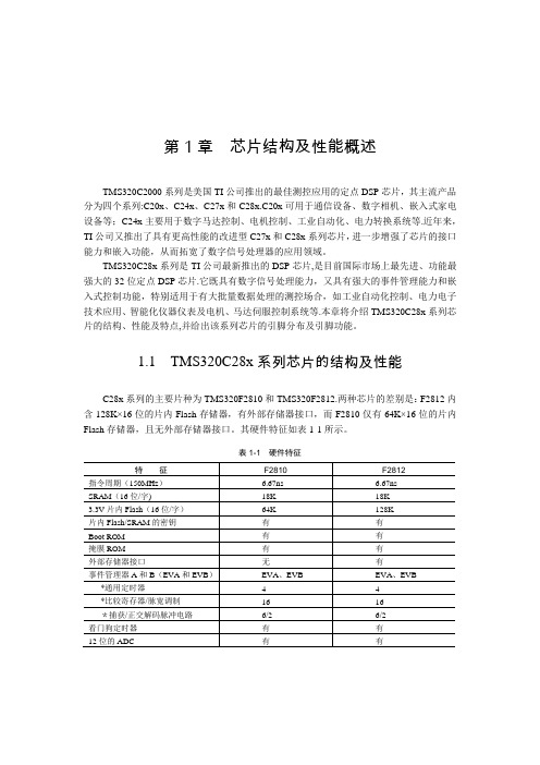
1.1 TMS320C28x系列芯片的结构及性能C28x系列的主要片种为TMS320F2810和TMS320F2812.两种芯片的差别是:F2812内含128K×16位的片内Flash存储器,有外部存储器接口,而F2810仅有64K×16位的片内Flash存储器,且无外部存储器接口。
其硬件特征如表1-1所示。
表1-1 硬件特征TMS320C28x系列DSP的CPU与外设(上)·2·注:‡“S”是温度选择(-40℃~ +125℃)的特征化数据,仅对TMS是适用的。
‡‡产品预览(PP):在开发阶段的形成和设计中与产品有关的信息,特征数据和其他规格是设计的目标。
TI保留了正确的东西,更换或者终止了一些没有注意到的产品.高级信息(AI):在开发阶段的取样和试制中与新产品有关的信息,特征数据和其他规格用以改变那些没有注意到的东西.产品数据(PD):是当前公布的数据信息,产品遵守TI的每项标准保修规格,但产品加工不包括对所有参数的测试。
大连东福彩色液晶显示器 EDM12832A 模块使用手册说明书

EDM12832A 模块使用手册1.使用范围-------------------------------------------------22.质量保证-------------------------------------------------23.性能特点-------------------------------------------------24.外形图----------------------------------------------------65.I/O接口特性--------------------------------------------66.质量等级-------------------------------------------------157.可靠性-------------------------------------------------178.生产注意事项-------------------------------------------189.使用注意事项-------------------------------------------19LCD 模块使用手册1.使用范围该检验标准适用于大连东福彩色液晶显示器有限公司设计提供的标准液晶显示模块。
如果在使用中出现了异常问题或没有列明的项目,建议同最近的供应商或本公司联系。
2.质量保证如在此手册列明的正常条件下使用、储存该产品,公司将提供12个月的质量保证。
3.性能特点3-1.性能:显示方式 : 反射、正显黄绿色 STN LCD显示颜色 : 显示点: 深蓝色背景: 黄绿色显示形式: 128(w)×32(h) 全点阵输入数据 : 来自MPU的8位并行数据接口Duty驱动路数: 1/32视角: 6 点控制器:KS0108B(Built-in)3-2.机械性能:项目规格单位外形尺寸 110.0(W)×65.0(H) ×10.0 Max.(T) mm显示点阵数 128(W) ×32(H) Dots —视域 76.0(W)×25.0(H) mm显示图形域73.0885(W)×18.2245(H) mm 点间距0.5715(W)×0.5715(H) mm点尺寸0.508(W)×0.508(H) mm78 g重量 Approx.LCD 模块使用手册3-3. 极限参数:项 目 符 号 最小值最大值单位 注 释逻辑 Vdd -0.3 7.0 V电源电压LCD 驱动 Vdd – Vee -0.3 7.0 V输入电压 Vi 0 Vdd V 操作温度 Top 0 50 ℃ 储存温度 Tstg -20 70 ℃ 湿度 — — 90 %RH3-4. 电气特性:3-4-1. 电气参数项 目 符 号 条 件 最小值典型值 最大值 单 位 逻辑 Vdd 4.7 5.0 5.3电源电压LCD 驱动 Vdd–Vee 4.7 — 5.3高电平 Vih Vdd=5V ±5% 0.7Vdd — Vdd输入电压低电平 Vil 0 — 0.3Vdd V高电平 Vih I OH =200UA2.4——输出电压低电平 Vil I 0L=1.6mA —— 0.4 频 率 Fflm Vdd=5V 65 70 75 Hz逻辑 Idd — 10.5 18.0功 耗 LCD 驱动 Iee Vdd=5V Vdd–Vee=5.0VFflm=70HzmA Ta= 0℃φ=0°,θ=0°— 5.2 5.4Ta= 25℃φ=0°,θ=0°4.755.0 5.25 LCD 驱动电压 (推荐电压) Vdd–Vee Ta= 50℃φ=0°,θ=0° 4.6 4.8 —VNote: <1> 驱动路数=1/32 <2> 所有点在静态条件下LCD 模块使用手册3 -5. 电光特性项 目 符号温度 条件 最小值典型值最大值 单位 注释 0℃ — 5.2 5.425℃ 4.75 5.0 5.25LCD 驱动电压(推荐电压)V op 50℃ φ=0°,θ=0° 4.6 4.8 — V 1,2,5 0℃ — 900 1200 上升时间 tr 25℃ — 150 2000℃ — 1200 2500响应 时间衰退时间 td 25℃ φ=0°,θ=0°— 200 250mS 1,3,5垂直 -35 — 35视 角 Δφ 25℃ 水平 -30 — 30deg. 1,4,5对比度 K 25℃ φ=0°,θ=0° 2.0 5.0 — — 1,5,6注意:<1> φ和θ的定义<2> 在此电压范围内能获得对比度大于2(k ≥2)LCD 模块使用手册注意:<4>视角定义注意:<5> 光学测量系统温度控制室(ΔΦ) ΔΦ=|Φ1-Φ2|选择点的亮度(B1)外形图 非选择点的亮度(B2)4.5. I/O 接口特性5-1. I/O 接口表:管脚号 符号 功 能 1 Vee LCD 驱动电压(可调) 2 Vdd 电源电压(+5V) 3 Vss 地(GND)4 E使能信号:当R/W=“L ”,E 下降沿锁存数据线上的数据;当R/W=“H ”,E=“H ”,读DDRAM 的数据到数据线上。
CS1242_Datasheet_cn

深圳市芯海科技有限公司
2 -28
CS1242 用户手册
保密文档
图列表
图 1 CS1242 原理框图.......................................................................................................................... 5 图 2 CS1242 管脚图.............................................................................................................................. 7 图 3 CS1242 时序图............................................................................................................................ 11 图 4 多路输入选择原理框图 ............................................................................................................. 13 图 5 外部晶振连接图 ......................................................................................................................... 15
3 CS1242 功能模块描述 ................................................................................................................. 13
研控科技 ESS28-R 系列 总线型集成式电机 用户手册说明书
目录前言 (1)1概述 (2)1.1产品介绍 (2)1.2特性 (2)1.3应用领域 (2)1.4 产品命名规则 (2)2性能指标 (3)2.1电气特性 (3)2.2使用环境 (3)3安装 (4)3.1安装尺寸 (4)3.2安装方法 (4)4端口与接线 (5)4.1接线示意图 (5)4.2端口定义 (6)4.2.1状态指示灯 (6)4.2.2输入/输出端口 (6)4.3控制信号连接 (7)4.3.1输入信号 (7)4.3.2输出信号 (7)5适配电机 (8)5.1技术规格 (8)6 MODBUS通讯协议 (9)6.1 MODBUS寄存器地址定义 (9)6.2 MODBUS常用功能码 (16)6.2.1读保持寄存器命令03 (16)6.2.2写单个寄存器命令06 (17)6.2.3写多个寄存器命令16 (17)6.2.4通讯错误码 (17)6.2.5应用示例 (19)7运动控制功能介绍 (21)7.1位置模式 (21)7.2速度模式 (22)7.3多段位置模式 (22)7.3.1 位置段参数介绍 (22)7.3.2 多段位控制方式 (23)7.4多段速度模式 (24)7.4.1 速度段参数介绍 (24)7.4.2 多段速度控制方式 (24)7.5回原点功能 (25)7.6 运动控制命令 (27)7.6.1 启动命令(0x0027) (27)7.6.2 停止命令(0x0028) (27)7.6.3 回原点命令(0x0030) (28)8报警排除 (29)9版本修订历史 (30)10保修及售后服务 (31)10.1保修 (31)10.2售后服务 (31)前言感谢您使用本公司总线型集成式电机。
在使用本产品前,请务必仔细阅读本手册,了解必要的安全信息、注意事项以及操作方法等。
错误的操作可能引发极其严重的后果。
声明本产品的设计和制造不具备保护人身安全免受机械系统威胁的能力,请用户在机械系统设计和制造过程中考虑安全防护措施,防止因不当的操作或产品异常造成事故。
鑫智造智能终端设备维修查询系统说明书
PC客户端说明书V4.XX~~~本软件长期免费使用,VIP享受高端稀缺资源特权~~~一:注册 (2)二:登录 (3)三:界面介绍 (3)3.1菜单功能和会员中心 (3)3.2目录介绍 (4)四:搜索功能 (5)4.1文件搜索 (5)4.2信号元件通病搜索 (6)4.3芯片搜索 (6)4.4鑫智造资源搜索 (6)五:使用鑫智造 (7)5.1PDF阅读器 (7)5.2PCB点位图查看 (7)5.2.1点位图高亮元件 (7)5.2.2点位图颜色设置 (8)5.2.3点位图镜像功能 (8)5.2.4点位图阻值功能 (9)5.2.5点位图查找功能 (9)5.2.6点位图文件互通功能 (9)5.2.7点位图双开功能 (10)5.3PCB板层走线功能 (11)5.4维修思路导图功能 (12)5.5收藏夹功能 (12)5.6标注功能 (13)5.7查看所有连接点功能 (15)六:副账号功能 (16)七:常见问题 (17)鑫智造客户端安装成功后,打开客户端,点击注册账号。
中国大陆用户使用手机注册,非中国大陆用户请下载国际中文版按照次方法进行注册。
输入账号或注册的手机号、密码,点击登录按钮。
三:界面介绍3.1菜单功能和会员中心常用功能都在菜单中有,也可以在会员中心可以查看:VIP到期时间、提现、兑换码兑换、购买VIP、充值记录、副账号管理、活动订单、提供资料、新手帮助、修改密码、修改手机号、分享推广软件、标注领取/管理。
3.2目录介绍目录包含:视频教程、手机平板、笔记本、主板、显卡、液晶电视、定制专区、收藏夹。
其中,定制区是单独收费区域。
文件夹前面带“+”的,是有下一层目录或文件,文件夹前面没有“+”的,是没有下一层目录。
普通文件夹永久免费使用,带VIP字眼的文件夹需要VIP权限(如下图)点位图文件格式是pcb/fz/brd等,电路图等文件格式是pdf。
目录有收起功能。
四:搜索功能搜索功能分为文件搜索、信号元件通病搜索、芯片搜索、鑫智造资源搜索。
SIEBAS32

Hardw. Flash(硬件闪存)
Applic. Func.Package(应用程序函数包)
• 此命令用于设置函数包。 • 该命令用于显示所有现存的函 数包。启动此命令时就设定了 所选的函数包。这样,系统搜 索连接器名时,首先会在已选 定的函数包中进行搜索。如果 搜索的连接器位于此函数包中, 则搜索时间会显著减少——尤 其是在目标处理器模块只有限 量的计算时间的情况下。 • 如果搜索的连接器不在此函数 包中,那么操作系统会对所有 现存函数包进行搜索
SIBAS32使用说明
调试车间 :曹宇 2009年11月
目录
程序结构
• Monitor程序界面分为两个部分,一个是标 准功能,一个是附加功能
Window菜单
Work open 打开工作窗口 Lines open 打开线性图表 Bars open 打开柱状图表 Tile 平铺窗口 Cascade 层叠窗口 Set 设置窗口 Close 关闭窗口 Close All 关闭所有窗口 Exit 退出窗口
SIBAS32支持的三类窗口 • • • • 工作窗口 条形图窗口 线图窗口 在通常的 Windows 方式 下,可利用鼠标移动窗口 或按照需要改变窗口大小。 用鼠标单击就可激活窗口。 • 除了这些鼠标控制活动之 外,Window(窗口)菜 单标题的命令还启用了窗 口管理职能
工作窗口
条形图窗口
线图窗口
• Applic. Menu(应用程序菜单)
Atmel ATmegaS128 微控制器商品说明书

The new Atmel ® AVR ® ATmegaS128 microcontroller (MCU) brings the industry-leading AVR core to the aerospace industry. The ATmegaS128 MCU is designed for enhanced radiation performance and increased reliability in space applications. It takes advantage of mature Atmel AVR tools designed and used in the mass market worldwide for many years. The ATmegaS128 microcontroller targets many of the most common space applications, which typically require a small footprint, low power and analog control of motors and sensors.Key FeaturesHigh-performance, Low-power 8-bit Atmel AVR MCU• Advanced RISC architecture / Up to 8MIPS• On-chip 2-cycle multiplier• 3V-3.6V / 0 - 8MHz operating voltages & speed grades High-endurance Non-volatile Memory • 128 Kbytes of Flash program memory• 4 Kbytes EEPROM – 4 Kbytes internal SRAM1Advance Risc Architecture 8 Mips3.0 3-55 • Up to 64 Kbytes optionalexternal memory space • SPI interface for in-system programmingPeripheral Features • Two 8-bit and two 16-bit timers/counters • 6 PWM channels • 8-channel, 10-bit ADC• TWI/USARTs/SPI serial interface • Programmable watchdog timer • On-chip analog comparator Special Microcontroller Features• Power-on reset and programmable brown-out detection• Internal calibrated RC oscillator • External and internal interrupt sources• Six Sleep modes: Idle, ADC Noise Reduction, Power-save, Power-down, Standby, and Extended StandbyKey Highlights for Space Environment• Full wafer lot traceability • 64-lead ceramic package (CQFP) • Space screening • Space qualification• Total ionizing Dose: up to 30 Krad (Si)• Single event latch-up LET > 62.5MeV.cm²/mg• Single event upset LET > 3 MeV.cm²/mg•SEU 10-3 to 10-1 error/ device/dayATmegaS128 Starter kitTo ease your design process and reduce time-to-market, Atmel delivers a complete starter kit STK600 and development system for the ATmegaS128 AVR microcontroller. With its advanced features for proto-typing and testing new designs, the kit gives designers a head start for developing code on AVR devices. Customers can start with the industrial version using the ATmega128 MCU or the Space Version ATme-gaS128 device as both share the same pinout.Atmel Corporation 1600 Technology Drive, San Jose, CA 95110 USA T : (+1)(408) 441. 0311 F : (+1)(408) 436. 4200 | © 2015 Atmel Corporation. / Rev.: Atmel-45160A-ATmegaS128-Aerospace-Rad-Tolerant-Flyer_E_US_102015Atmel,® Atmel logo and combinations thereof, Enabling Unlimited Possibilities,® and others are registered trademarks or trademarks of Atmel Corporation in U. S. and other countries. Other terms and product names may be trademarks of others.Disclaimer: The information in this document is provided in connection with Atmel products. No license, express or implied, by estoppel or otherwise, to any intellectual property right is granted by this document or in connection with the sale of Atmel products. EXCEPT AS SET FORTH IN THE ATMEL TERMS AND CONDITIONS OF SALES LOCATED ON THE ATMEL WEBSITE, ATMEL ASSUMES NO LIABILITY WHATSOEVER AND DISCLAIMS ANY EXPRESS, IMPLIED OR STATUTORY WARRANTY RE-LATING TO ITS PRODUCTS INCLUDING, BUT NOT LIMITED TO, THE IMPLIED WARRANTY OF MERCHANTABILITY, FITNESS FOR A PARTICULAR PURPOSE, OR NON-INFRINGEMENT. IN NO EVENT SHALL ATMEL BE LIABLE FOR ANY DIRECT, INDIRECT, CONSEQUENTIAL, PUNITIVE, SPECIAL OR INCIDENTAL DAMAGES (INCLUDING, WITHOUT LIMITATION, DAMAGES FOR LOSS AND PROFITS, BUSINESS INTERRUPTION, OR LOSS OF INFORMATION) ARISING OUT OF THE USE OR INABILITY TO USE THIS DOCUMENT, EVEN IF ATMEL HAS BEEN ADVISED OF THE POSSIBILITY OF SUCH DAMAGES. Atmel makes no representations or warranties with respect to the accuracy or completeness of the contents of this document and reserves the right to make changes to specifications and products descriptions at any time without notice. Atmel does not make any commitment to update the information contained herein. Unless specifically provided otherwise, Atmel products are not suitable for, and shall not be used in, automotive applications. Atmel products are not intended, authorized, or warranted for use as components in applications intended to support or sustain life.Atmel StudioAtmel Studio is the integrated development platform (IDP) for developing and debugging Atmel AVR and Atmel | SMART ARM ® processor-based MCU applications. The Atmel Studio IDP gives you a seamless and easy-to-use environment to write, build and debug your applications written in C/C++ or assembly code. Atmel Studio supports all 8- and 32-bit AVR MCUs. It also connects seamlessly to Atmel debuggers and development kits.Atmel Software FrameworkThe Atmel Software Framework (ASF) is an MCU software library providing a 1,600 project examples of embedded software for Atmel Flash-based MCUs, including AVR and Atmel | SMART devices. This library contains basic C code examples for all ATmegaS128 peripherals.Application NotesIn addition to the Atmel Software framework, Atmel provides a broad range of application notes to implement different peripherals of the ATmegaS128 device. Most of those ap-plication notes are provided with source code in C language.。
SR-DSP2812V20开发套件使用手册

SR-DSP2812V20 开发套件使用手册(版本:1.0)长沙赛睿技术有限公司前言感谢您购买本公司的产品,在使用本产品前,请仔细阅读本使用说明书。
本用户指南是TMS320F2812 嵌入式DSP 控制模板硬件使用说明书,详细描述了SR-DSP2812 的硬件构成、原理,以及它的使用方法和编程指导。
如果您有任何意见和建议请发送邮件至:cyrui@。
同时欢迎您访问我们的网站,获取更多产品信息。
在你开始您的DSP学习开发之旅前,请您仔细核对本套件清单,具体如下:1.SR-DSP2812 开发板 1 块;2.9V直流电源 1 只;3.配套串口线 1 根;4.配套光盘 1 张;5.固定铜螺柱 4 只。
目录第1 章入门 (1)1.1 概述 (1)1.2 特点 (1)1.3 技术指标 (2)第2 章 TMS320F2812 基本系统 (3)2.1 TMS320F2812 时钟 (3)2.1.1 CPU 时钟 (3)2.1.2 片上外设时钟 (3)2.2 TMS320F2812 存储空间的配置 (4)2.2.1 ‘F2812 片上SARAM (6)2.2.2 ‘F2812 片上FLASH 和OTP (7)2.2.3 ‘F2812 外部存储器接口 (8)2.3 McBSP (8)2.4 SPI (8)2.5 SCI (9)2.6 CAN (9)2.7 ADC (9)2.8 事件管理器 (9)2.9 定时器 (10)2.10 F2812 的中断 (10)2.11 ‘F2812 的复位 (11)2.11 JTAG (12)2.12 ‘F2812 工作方式的配置 (12)第3 章测试程序 (13)3.1 GPIO 测试 (13)3.2 SCI 测试 (14)3.3 SPI 测试 (15)3.4 CAN 测试 (16)3.5 PWM 测试 (17)3.6 McBSP 测试 (18)3.7 A/D 测试 (19)3.8 TIMER0 测试 (20)3.9 EvTimer 测试 (21)3.10 外部Ram 测试 (21)3.11 外部FLASH 测试 (23)第1章入门1.1 概述SR-DSP2812 开发套件主要包含SR-DSP2812 的硬件系统与相应的测试软件两部分。
ATmegaS128-STK600 硬件与软件入门指南说明书

APPLICATION NOTEHardware and Software Getting StartedATmegaS128-STK600 IntroductionThis document guides you step by step to setup the hardware and software, to program and run your first code with the ATmegaS128 device. RequirementsTo use this “Getting S tarted” document you need to gather the following materials: - One STK600 kit (ATSTK600)- One routing board (STK600-RC064M-9)- One ATmegaS128 board (ATmegaS128-ZC-EK)- Atmel Studio available from : /Microsite/atmel-studio- “ATmegaS128_led_chaser.zip” software FileObjectiveThe aim is prepare the hardware, program and run a short demo based on the “led chaser” software.ATmegaS128-STK600 [APPLICATION NOTE] Atmel-41075A-Aero-Hardware and Software Getting Started -11/2015221Hardware Configuration1.1Step 1.Unpack the STK600 kit and install the RC064M-9 routing board as shown on the figure below.Install the ATmegaS128-ZC-EK board as shown on the figure below.ATmegaS128-STK600 [APPLICATION NOTE] Atmel-41075A-Aero-Hardware and Software Getting Started -11/2015 33ATmegaS128-STK600 [APPLICATION NOTE] Atmel-41075A-Aero-Hardware and Software Getting Started -11/201544Connect an USB cable between your workstation and the STK600 board and connect an 8-wires flat cablebetween the ports A(0-7) and LED(0-7) as shown in the figure below. Before connecting the USB cable, set the power s witch to “Off” positio n. Those two cables are supplied in the STK600 kit.ATmegaS128-STK600 [APPLICATION NOTE]Atmel-41075A-Aero-Hardware and Software Getting Started -11/201555 Verify that the jumpers and the switch are configured as shown on the figure below. The jumpers VTARGET, RESET, AREF0, AREF1 must be set and the c lock switch must be set to “INT” position.1.5 Step 5.Connect a 10-wires flat cable on the JTAG connector as shown on the figure below. The cable is supplied in the STK600 kit.Move the power s witch to “ON” position. The hardware configuration is now complete. The next step will consist to run the application software.ATmegaS128-STK600 [APPLICATION NOTE] Atmel-41075A-Aero-Hardware and Software Getting Started -11/2015662 Software ConfigurationThis section guides you in few steps to prepare your workstation to program and run the “led chaser” demo.Prerequisite 1.: download Atmel Studio from the URL /Microsite/atmel-studio and install it on your workstation.Prerequisite 2.: unzip the “l ed chaser ” demo file .2.1 Step 6.D ouble click on the file “Led_Chaser.atsln”. It makes run Atmel Studio (if a window requesting an update appears, you can close it).2.2 Step 7.Click on the programming Icon as shown on the figure below.A window should pop as shown on the figure below.Select STK600 as tools, ATmega128A as device and JTAG as Interface then click on the “Apply” button. Note: For the development tools, the ATmegaS128, is “seen” as an ATmega128A.In return, the system should display the information shown on the figure below, meaning that the hardware configuration has been recognized by the system.ATmegaS128-STK600 [APPLICATION NOTE] Atmel-41075A-Aero-Hardware and Software Getting Started -11/2015 77ATmegaS128-STK600 [APPLICATION NOTE] Atmel-41075A-Aero-Hardware and Software Getting Started -11/201588Click on the “Read” button to get the signature bytes of the ATmegaS128.The voltage supply of the ATmegaS128 device can be adjusted from your workstation. If the voltage level is close to zero, it is not possible to read the signature bytes. Therefore the voltage supply must be tuned. You should read the value 0x1E9702 meaning that the system is able to communicate with the ATmegaS128 device. If an error message comes up, check the device voltage by clicking on the “Read” button. If it is not possible, click on the “board settings” option from the left menu.Note : The ATmegaS128 is a 3.3V device while the ATmega128A is a 2.7-5.5V device. Therefore, the ATmega128A lets you the choice between 3.3V or 5V. For the ATmegaS128 please set voltage to 3.3V.Adjust the voltage level by means of the cursor as shown on the figure be low then click on the “Write” button.Verify the target voltage and the availability of the signature bytes (0x1E9702).2.5 Step 10. Configuring the fuse bytes of the ATmegaS128.Click on the “Fuses” option from the left menu.Those fuse bytes enable to configure several device hardware parameters.Verify that the M103C fuse is unchecked, that the JTAGEN and SPIEN are checked, then click on the “Program”button.ATmegaS128-STK600 [APPLICATION NOTE] Atmel-41075A-Aero-Hardware and Software Getting Started -11/2015 99ATmegaS128-STK600 [APPLICATION NOTE] Atmel-41075A-Aero-Hardware and Software Getting Started -11/20151102.6 Step 11.Programming the code.Click on the “Memories” option from the left menu then click on “Erase now” button to erase the device. Find the file “Led_Chaser.elf” on your wor kstation from the path \led_chaser\GccBoardProject2\Debug, then click on the “Program” button .The demo should start after few seconds.Congratulations. You have now completely set up your hardware and software environment and programmed your first AVR based demo. Enjoy by changing the source code and reprogramming the chip.3 Revision HistoryATmegaS128-STK600 [APPLICATION NOTE] Atmel-41075A-Aero-Hardware and Software Getting Started -11/2015 111。
基于ATMEGA328P的无线TALLY系统

基于ATMEGA328P的无线TALLY系统摘要:本文介绍了一种基于ATMEGA328P和汇承HC-12传输模块的无线TALLY 系统,该系统具响应快速,显示准确,传输稳定,性价比高等特点。
文章从工作原理、电路设计、元器件选型、程序开放等方面对该系统进行了简要阐述。
关键字:无线TAllY系统 ATMEGA328P一、研发背景近年来,EFP电子现场制作(Electronic Field Production)系统凭借其灵活、机动、便携等特点,在突发事件的新闻报道工作中使用频率逐渐提高,索尼AWS-750便携切换台在EFP系统中得到广泛的应用。
根据平日转播工作的实际情况,急需一种灵活、可靠的摄像机切灯提示系统,来提示摄像师,导播正在使用此台摄像机的拍摄画面,不要对此台摄像机进行不必要的调整。
切灯提示系统保证了摄像师构图的稳定性,提升了节目播出的安全性。
基于ATMEGA328P微控制器,配合汇承HC-12无线串口通讯模块的无线切灯提示系统,可满足在日常转播工作中,编辑部门对切灯提示的需求,此系统在满足EFP 系统节目制作的同时,也能够在转播车系统中使用。
项目拥有良好的可扩展性和高可用性,运维成本低廉,符合立项的需求。
二、项目概况为了延续EFP系统灵活机动的特性,计划设计一套无线切灯提示系统,采取一发多收的模式。
接收端可放置于摄像机的机头灯安装位上如图1所示,这样可以不用考虑摄像机的品牌和型号,适配程度显著提升。
设计使用OLED显示屏显示,通讯状态、本机讯道号和主切讯道号如图2所示。
设计使用内外切灯对摄像师和主持人进行分别的提示,可显示红、绿、黄三色,主切、预切、主预同切三种切灯如图3所示。
系统设置开机自检程序,设计电源提示灯,方便判断各元器件的工作状况。
断电后本机讯道号不丢失。
使用三档拨轮开关分别调整本机讯道号,和LED灯珠亮度,以适应各种场景。
本系统,还应兼容日常工作中的转播车系统所使用的其他型号切换台,可对斯坦尼康、无线讯道、轨道摄像机等特种设备,进行切灯提示。
DSP2812深入讲解
DSP 的发展历史大致可以分成四个阶段:萌芽阶段、成长阶段、成熟阶段、突破阶段。 萌芽阶段:1982 年以前 在这段时期里为解决 Von Neumann 结构在进行数字信号处理时总线和存储器之间的瓶颈效应,许多公司投入 大量人力和物力开展了很多探索性的工作,研制出了一些 DSP 的雏形,如 AMI 的 S2811、INTEL 的 2920、 AT&T 的 DSP-1 和 NEC 的 uPD7720。但这些产品的运算速度都太慢,而且开发工具严重不足,无法进行大 规模的开发工作,还不能称作真正意义上的 DSP。第一片 DSP 是 1982 年 TI 公司出品的 TMS320C10,它是 —个 16 位的定点 DSP,采用了哈佛(Harvard)结构,有一个乘加器和一个累加器。TMS320C10 完成—次乘加 操作需要 390ns,即在一秒钟的时间内可以完成 250 万次左右的乘加运算。或许正是因为生产出了第一个 DSP, TI 公司在此后的三十几年中一直是 DSP 界的领军人物。 成长阶段:1982-1987 年 这段时间内各公司相继研制出了自己的 DDSP 并不断地改进。如 1985 年,TI 推出了 TMS320C20,它具备单 指令循环的硬件支持,寻址空间达到 64K 字,有专门的地址寄存器,一次乘加运算只需耗时 200ns。1987 年, MOTOROLA 公司推山了 DSP56001,采用 24 位的数据和指令,有专门的地址寄存器,可以循环寻址,累加 器有保护位,一坎乘加运算只需耗时 75ns。此外,在这段时期中还有一些代表产品,如 AT&T 的 DSPl6A、 AD 的 ADSP-2100,TI 的 TMS320C50。 成熟阶段:1987-1997 年 在这个阶段里各公司不断借鉴相互的优点,并完善自身的设计,推出了特点分明的产品,如 TI 的 TMS320C54 系列、AD 的 ADSP2100 系列、Lucent(前身为 AT&T)的 DSPl600 系列和 MOTOROLA 的 DSP56000 系列。 它们在供电上都支持 3.3v,片上的存储器也较大,都有 JTAG 模块支持用户在线调试。另外,TI 等公司还专门 提供 DSP 的内核,为一些专用集成电路(ASIC)的开发提供了空间。此外,在成熟阶段还首次出现了多处理核 的 DSP,如 TI 的 TMS320C80 和 MOTOROLA 的 MC68356 等,虽然它们的推出在商业上并不算成功,但却 指明了一个有潜力的发展方向。 突破阶段:1997 年直至现在 这段时间里 DSP 的发展非常迅速,各公司相继建立了自己从定点到浮点,从低端到高端,从通用到专用完整 的产品系列,并且在 DSP 设计上有了大的飞跃,推出了一些性能突出的产品。很多公司相继采用先进技术研 制了计算性能很高的 DSP,如 AD 的 SHARC 系列、TI 的 TMS320C6000 系列、MOTOROLA 和 Agere(前身 为 Lucent 微电子)的 StarPro 等,每秒钟可以完成 1G 条以上的指令,计算速度惊人。TI 公司还研制出功耗最 小的 DSP TMS320C55 系列,为便携式设备提供了一个明智的选择。 回顾 DSP 发展的二十几年,也正是电子、信息和微电于技术快速发展的二十年,正是后者为 DSP 提供了必要 的技术支持和应用的广阔空间,使得 DSP 及其相关的技术日益受到人们的重视。
西门子SINAMICS S120 Startdrive 入门指南

4 Startdrive 组态工具 ....................................................................................................................... 37
4.1 4.1.1 4.1.2
1.7
附加信息 ..................................................................................................................... 18
1.8
OpenSSL 的使用 .......................................................................................................... 20
1.9
文档目标 ..................................................................................................................... 21
1.10
基本数据保护准则 ....................................................................................................... 22
4.3
操作界面 - 控制面板 .................................................................................................... 51
DSP2812寄存器汇总
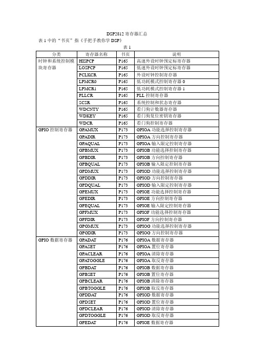
PIE, INT9组使能寄存器
PIEIFR9
P201
PIE, INT9组标志寄存器
PIEIER10
P201
PIE, INT10组使能寄存器
PIEIFR10
P201
PIE, INT10组标志寄存器
PIEIER11
P201
PIE, INT11组使能寄存器
PIEIFR11
P201
PIE, INT11组标志寄存器
P187
CPU定时器2控制寄存器
TIMER2TPR
P187
CPU定时器2预定标寄存器低位
TIMER2TPRH
P187
CPU定时器2预定标寄存器高位
CPU中断寄存器
IER
P196
CPU中断使能寄存器
IFR
P196
CPU中断标志寄存器
INTM
P196
CPU全局中断标志位
PIE(外设中断控制器)中断寄存器
EVAIFRA
P257
EVA中断标志寄存器A
EVAIMRA
P257
EVA中断屏蔽寄存器A
EVAIFRB
P257
EVA中断标志寄存器B
EVAIMRB
P257
EVA中断屏蔽寄存器B
EVAIFRC
P257
EVA中断标志寄存器C
EVAIMRC
P257
EVA中断屏蔽寄存器C
EVBIFRA
P257
EVB中断标志寄存器A
P293
ADC自动序列状态寄存器
ADCRESULT0
P293
ADC转换结果缓冲寄存器0
ADCRESULT1
P293
ADC转换结果缓冲寄存器1
AD S 芯片手册 中文
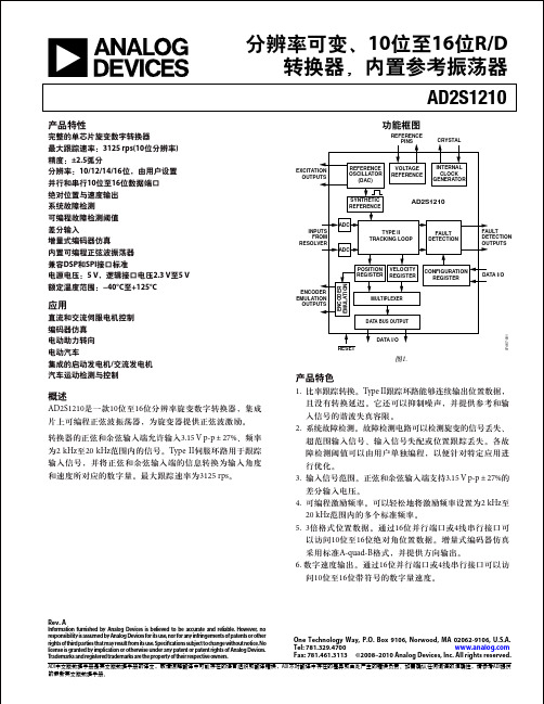
直流和交流伺服电机控制 编码器仿真 电动助力转向 电动汽车 集成的启动发电机/交流发电机 汽车运动检测与控制
概述
AD2S1210是一款10位至16位分辨率旋变数字转换器,集成 片上可编程正弦波振荡器,为旋变器提供正弦波激励。
转换器的正弦和余弦输入端允许输入3.15 V p-p ± 27%、频率 为2 kHz至20 kHz范围内的信号。Type II伺服环路用于跟踪 输入信号,并将正弦和余弦输入端的信息转换为输入角度 和速度所对应的数字量。最大跟踪速率为3125 rps。
旋变-数字转换 ....................................................................... 16 故障检测电路 ......................................................................... 16 片上可编程正弦波振荡器 ................................................... 18 合成参考生成 ......................................................................... 18 AD2S1210配置............................................................................. 20 工作模式................................................................................. 20 寄存器映射................................................................................... 21 位置寄存器 ............................................................................. 21 速度寄存器 ............................................................................. 21
Moxa EDS-728 系列 24+4G 埠 Layer 2 Gigabit 模組化網管型乙太網路

EDS-728系列24+4G 埠Layer 2Gigabit模組化網管型乙太網路交換器特色與優點•4個Gigabit 連接埠和24個快速乙太網路連接埠,可連接銅質纜線和光纖•支援Turbo Ring 和Turbo Chain (對於250台交換器斷線復連時間小於20毫秒)1、RSTP/STP 和MSTP 網路備援•支援TACACS+、SNMPv3、IEEE 802.1X 、HTTPS 和SSH ,強化網路安全•透過網頁瀏覽器、CLI 、Telnet /序列主控台、Windows 管理工具和ABC-01輕鬆管理網路•支援MXstudio ,輕鬆實現可視化的工業網路管理認證簡介EDS-728系列採用多功能的模組化設計,可搭配不同的光纖和銅線模組組合,可以組建各種連線模式,靈活適用於所有自動應用網路。
模組化設計可讓您安裝多達4個Gigabit 連接埠和24個快速乙太網路連接埠。
EDS-728系列是針對Gigabit 網路骨幹備援所特別設計,利用模組化配置為網路擴充提供高度彈性。
透過EDS-728系列進階管理和安全特性,將可確保頂級的網路效能、安全性與可靠性。
EDS-728系列也具備工業級結構,包括可用於自動配置備份的主控台連接埠,以及從水平和垂直視角都可輕鬆查看的多角度LED 故障排除面板。
附加特色與優點•命令列介面(CLI )快速設定主要網管功能•透過Q-in-Q 標籤支援進階VLAN 功能•軟體型IEEE 1588PTPv2(精確時間協定)可提供精確的網路時間同步•DHCP Option 82以不同原則指派IP 位址•支援EtherNet/IP 和Modbus TCP 通訊協定以進行設備管理和監控•相容於PROFINET 通訊協定以進行透通式數據傳輸•IGMP snooping 和GMRP ,用於過濾多點播送流量•IEEE 802.1Q VLAN 以及GVRP 通訊協定,可簡化網路規劃•QoS (IEEE 802.1p/1Q 和TOS/DiffServ )提高資料傳送穩定性•Port Trunking 可將頻寬使用率最佳化•SNMPv1/v2c/v3,支援不同層級的網路管理•RMON 提供主動且有效率的網路監控•頻寬管理可預防不穩定的網路狀態出現•連接埠鎖定功能可依據MAC 位址封鎖未經授權的存取•Port mirroring 可用於線上除錯•發生狀況時可透過電子郵件或是繼電器輸出自動發出告警•數位輸入可將感應器和警告整合至IP 網路•備援雙直流(DC)電源輸入•可透過網頁瀏覽器、Telnet /序列主控台、CLI 、Windows 管理工具,以及ABC-01自動備份配置器進行配置設定規格Input/Output InterfaceAlarm Contact Channels 2,Relay output with current carrying capacity of 1A @24VDC Digital Input Channels 2Digital Inputs+13to +30V for state 1-30to +3V for state 0Max.input current:8mA1.Gigabit 乙太網路斷線復連時間小於50毫秒Ethernet InterfaceModule6slots for any combination of4-port interface modules,10/100BaseT(X)or100BaseFX;2slots for any combination of2-port interface modules,10/100/1000BaseT(X)or1000BaseSFPStandards IEEE802.1D-2004for Spanning Tree ProtocolIEEE802.1p for Class of ServiceIEEE802.1Q for VLAN TaggingIEEE802.1s for Multiple Spanning Tree ProtocolIEEE802.1w for Rapid Spanning Tree ProtocolIEEE802.1X for authenticationIEEE802.3for10BaseTIEEE802.3ab for1000BaseT(X)IEEE802.3ad for Port Trunk with LACPIEEE802.3u for100BaseT(X)and100BaseFXIEEE802.3x for flow controlIEEE802.3z for1000BaseXEthernet Software FeaturesFilter GMRP,GVRP,IGMP v1/v2,QinQ VLAN,802.1Q VLAN,VLAN unawareIndustrial Protocols EtherNet/IP,Modbus TCPManagement Back Pressure Flow Control,BOOTP,DDM,DHCP Option66/67/82,DHCP Server/Client,Flow control,IPv4,LLDP,Port Mirror,RARP,RMON,SMTP,SNMP Inform,SNMPv1/v2c/v3,Syslog,Telnet,TFTPMIB Bridge MIB,Ethernet-like MIB,MIB-II,P-BRIDGE MIB,Q-BRIDGE MIB,RMON MIBGroups1,2,3,9,RSTP MIBRedundancy Protocols Link Aggregation,MSTP,RSTP,STP,Turbo Chain,Turbo Ring v1/v2Security Broadcast storm protection,HTTPS/SSL,Port Lock,RADIUS,SSH,TACACS+Time Management NTP Server/Client,SNTP,IEEE1588v2PTP(software-based)Switch PropertiesIGMP Groups256MAC Table Size16KMax.No.of VLANs64Packet Buffer Size32MbitsPriority Queues4VLAN ID Range VID1to4094Serial InterfaceConsole Port RS-232(TxD,RxD,GND),8-pin RJ45(115200,n,8,1)Power ParametersConnection2removable6-contact terminal block(s)Input Current0.82A@24VDCInput Voltage24VDC,Redundant dual inputsOperating Voltage12to45VDCOverload Current Protection SupportedReverse Polarity Protection SupportedPhysical CharacteristicsIP Rating IP30Dimensions362.4x142.5x128mm(14.27x5.61x5.04in)Weight1950g(4.30lb)Installation DIN-rail mounting,Wall mounting(with optional kit)Environmental LimitsOperating Temperature0to60°C(32to140°F)Storage Temperature(package included)-40to85°C(-40to185°F)Ambient Relative Humidity5to95%(non-condensing)Standards and CertificationsFreefall IEC60068-2-32EMC EN55032/24EMI CISPR32,FCC Part15B Class AEMS IEC61000-4-2ESD:Contact:6kV;Air:8kVIEC61000-4-3RS:80MHz to1GHz:10V/mIEC61000-4-4EFT:Power:4kV;Signal:2kVIEC61000-4-5Surge:Power:2kV;Signal:1kVIEC61000-4-6CS:10VIEC61000-4-8PFMFMaritime ABS,DNV-GL,LR,NKSafety EN60950-1,UL508,UL60950-1,CSA C22.2No.60950-1Shock IEC60068-2-27Vibration IEC60068-2-6MTBFTime191,203hrsStandards Telcordia SR332WarrantyWarranty Period5yearsDetails See /tw/warrantyPackage ContentsDevice1x EDS-728Series switchCable1x RJ45-to-DB9console cableDocumentation1x document and software CD1x product certificates of quality inspection,Simplified Chinese1x product notice,Simplified Chinese1x quick installation guide1x warranty cardNote SFP modules and/or modules from the IM Module Series need to be purchased separatelyfor use with this product.尺寸訂購資訊Model Name Layer Total No.of PortsIM-2G Series Module10/100/1000BaseT(X)or1000BaseSFPIM Series Module10/100BaseT(X)and/or100BaseFXOperating Temp.EDS-72810G2282slots for up to410/100/1000BaseT(X)or1000BaseSFP ports6slots for up to2410/100BaseT(X)and/or100BaseFX ports0to60°C配件(選購)IM Module SeriesIM-1LSC/3TX Fast Ethernet interface AC module with310/100BaseT(X)ports,1100BaseFX single-mode port with SCconnector for80km transmission,0to60°C operating temperatureIM-2GSFP Gigabit Ethernet interface module with21000BaseSFP slots,0to60°C operating temperatureIM-2GTX Gigabit Ethernet interface module with210/100/1000BaseT(X)ports,0to60°C operating temperature IM-2MSC/2TX Fast Ethernet interface module with210/100BaseT(X)ports,2100BaseFX multi-mode ports with SCconnector,0to60°C operating temperatureIM-2MST/2TX Fast Ethernet interface module with210/100BaseT(X)ports,2100BaseFX multi-mode ports with STconnectors,0to60°C operating temperatureIM-2SSC/2TX Fast Ethernet interface module with210/100BaseT(X)ports,2100BaseFX single-mode ports with SCconnectors,0to60°C operating temperatureIM-4MSC Fast Ethernet interface module with4100BaseFX multi-mode ports with SC connector,0to60°Coperating temperatureIM-4MST Fast Ethernet interface module with4100BaseFX multi-mode ports with ST connectors,0to60°Coperating temperatureIM-4SSC Fast Ethernet interface module with4100BaseFX single-mode ports with SC connector,0to60°Coperating temperatureIM-4TX Fast Ethernet interface module with410/100BaseT(X)ports,0to60°C operating temperatureStorage KitsABC-01Configuration backup and restoration tool for managed Ethernet switches and AWK Series wireless APs/bridges/clients,0to60°C operating temperatureSFP ModulesSFP-1G10ALC WDM-type(BiDi)SFP module with11000BaseSFP port with LC connector for10km transmission;TX1310nm,RX1550nm,0to60°C operating temperatureSFP-1G10ALC-T WDM-type(BiDi)SFP module with11000BaseSFP port with LC connector for10km transmission;TX1310nm,RX1550nm,-40to85°C operating temperatureSFP-1G10BLC WDM-type(BiDi)SFP module with11000BaseSFP port with LC connector for10km transmission;TX1550nm,RX1310nm,0to60°C operating temperatureSFP-1G10BLC-T WDM-type(BiDi)SFP module with11000BaseSFP port with LC connector for10km transmission;TX1550nm,RX1310nm,-40to85°C operating temperatureSFP-1G20ALC WDM-type(BiDi)SFP module with11000BaseSFP port with LC connector for20km transmission;TX1310nm,RX1550nm,0to60°C operating temperatureSFP-1G20ALC-T WDM-type(BiDi)SFP module with11000BaseSFP port with LC connector for20km transmission;TX1310nm,RX1550nm,-40to85°C operating temperatureSFP-1G20BLC WDM-type(BiDi)SFP module with11000BaseSFP port with LC connector for20km transmission;TX1550nm,RX1310nm,0to60°C operating temperatureSFP-1G20BLC-T WDM-type(BiDi)SFP module with11000BaseSFP port with LC connector for20km transmission;TX1550nm,RX1310nm,-40to85°C operating temperatureSFP-1G40ALC WDM-type(BiDi)SFP module with11000BaseSFP port with LC connector for40km transmission;TX1310nm,RX1550nm,0to60°C operating temperatureSFP-1G40ALC-T WDM-type(BiDi)SFP module with11000BaseSFP port with LC connector for40km transmission;TX1310nm,RX1550nm,-40to85°C operating temperatureSFP-1G40BLC WDM-type(BiDi)SFP module with11000BaseSFP port with LC connector for40km transmission;TX1550nm,RX1310nm,0to60°C operating temperatureSFP-1G40BLC-T WDM-type(BiDi)SFP module with11000BaseSFP port with LC connector for40km transmission;TX1550nm,RX1310nm,-40to85°C operating temperatureSFP-1GEZXLC SFP module with11000BaseEZX port with LC connector for110km transmission,0to60°C operatingtemperatureSFP-1GEZXLC-120SFP module with11000BaseEZX port with LC connector for120km transmission,0to60°C operatingtemperatureSFP-1GLHLC SFP module with11000BaseLH port with LC connector for30km transmission,0to60°C operatingtemperatureSFP-1GLHLC-T SFP module with11000BaseLH port with LC connector for30km transmission,-40to85°C operatingtemperatureSFP-1GLHXLC SFP module with11000BaseLHX port with LC connector for40km transmission,0to60°C operatingtemperatureSFP-1GLHXLC-T SFP module with11000BaseLHX port with LC connector for40km transmission,-40to85°C operatingtemperatureSFP-1GLSXLC SFP module with11000BaseLSX port with LC connector for1km/2km transmission,0to60°C operatingtemperatureSFP-1GLSXLC-T SFP module with11000BaseLSX port with LC connector for1km/2km transmission,-40to85°Coperating temperatureSFP-1GLXLC SFP module with11000BaseLX port with LC connector for10km transmission,0to60°C operatingtemperatureSFP-1GLXLC-T SFP module with11000BaseLX port with LC connector for10km transmission,-40to85°C operatingtemperatureSFP-1GSXLC SFP module with11000BaseSX port with LC connector for300m/550m transmission,0to60°Coperating temperatureSFP-1GSXLC-T SFP module with11000BaseSX port with LC connector for300m/550m transmission,-40to85°Coperating temperatureSFP-1GZXLC SFP module with11000BaseZX port with LC connector for80km transmission,0to60°C operatingtemperatureSFP-1GZXLC-T SFP module with11000BaseZX port with LC connector for80km transmission,-40to85°C operatingtemperaturePower SuppliesDR-120-24120W/2.5A DIN-rail24VDC power supply with universal88to132VAC or176to264VAC input byswitch,or248to370VDC input,-10to60°C operating temperatureDR-452445W/2A DIN-rail24VDC power supply with universal85to264VAC or120to370VDC input,-10to50°Coperating temperatureDR-75-2475W/3.2A DIN-rail24VDC power supply with universal85to264VAC or120to370VDC input,-10to60°C operating temperatureMDR-40-24DIN-rail24VDC power supply with40W/1.7A,85to264VAC,or120to370VDC input,-20to70°Coperating temperatureMDR-60-24DIN-rail24VDC power supply with60W/2.5A,85to264VAC,or120to370VDC input,-20to70°Coperating temperatureSoftwareMXview-50Industrial network management software with a license for50nodes(by IP address)MXview-100Industrial network management software with a license for100nodes(by IP address)MXview-250Industrial network management software with a license for250nodes(by IP address)MXview-500Industrial network management software with a license for500nodes(by IP address)MXview-1000Industrial network management software with a license for1000nodes(by IP address)MXview-2000Industrial network management software with a license for2000nodes(by IP address)MXview Upgrade-50License expansion of MXview industrial network management software by50nodes(by IP address) Rack-Mounting KitsRK-4U19-inch rack-mounting kitWall-Mounting KitsWK-32Wall-mounting kit,2plates,6screws,30.3x140x12.3mm©Moxa Inc.版權所有.2020年11月25日更新。
STM32F429I-DISCO开发板用户手册说明书

Open429Z-D User ManualContents1. Hardware introduction (2)1.1. What’s on board (2)2. Demo (4)2.1. ADC+DMA (4)2.2. CAN1 TO CAN2-Normal (5)2.3. DAC (5)2.4. DS18B20 (6)2.5. OV2640 (6)2.6. GPIO_Key (7)2.7. I2C (7)2.8. I2S_UDA1380 (8)2.9. NandFlash_SCB0 (8)2.10. SAI (9)2.11. SD_FatFS (9)2.12. SDIO (9)2.13. SPI (10)2.14. USART (11)3. Version update records (11)1. Hardware introduction 1.1. What’s on board[ Core interface ]1. STM32F429I-DISCO socketfor easily connecting the STM32F429I-DISCO 2. MCU pins connectorall the MCU I/O ports are accessible onexpansion connectors for further expansion 3. USB connectorUSB to UART via PL2303 USB TO UART board onboard MCU4. I2C1 / I2C2interface[ Other interfaces ]16. 5V DC jack17. 5V/3.3 V power input/outputusually used as power output, alsocommon-grounding with other user board 18. JTAG/SWD interfacefor debugging/programming[ Jumper ]easily connects to I2C peripherals such as I/O expander (PCF8574), FRAM (FM24CLXX), etc. 5. I2S2 / I2S3 / I2C1 interfacefor connecting I2S peripherals, such as Audio module.6. DCMI interfacefor connecting camera module 7. SDIO interfacefor connecting Micro SD module, features much faster access speed rather than SPI 8. CAN1 interfacecommunicates with accessory boards which feature the CAN device conveniently 9. CAN2 interfacecommunicates with accessory boards which feature the CAN device conveniently 10. UART3 interfaceeasily connects to RS232, RS485, USB TO 232, etc11. SPI1/SPI4 + AD/DA interfaceeasily connects to SPI peripherals such as DataFlash (AT45DBxx), SD card, MP3 module, etc MP3SPI1 features AD/DA alternative function, supports connecting AD/DA module as well 12. UART2 interfaceeasily connects to RS232, RS485, USB TO 232, etc13. 8-bit FSMC interfaceeasily connects to peripherals such as NandFlash, Ethernet, etc 14. SAI1 interfacefor connecting Audio peripherals, such as UDA1380 etc15. One-WIRE interfaceeasily connects to ONE-WIRE devices (TO-92 package), such as temperature sensor (DS18B20), electronic registration number (DS2401), etc.16. Joystick jumpershort the jumper to connect the joystick to default I/Os used in example code;open the jumper to connect the joystick to custom I/Os via jumper wires. 17. BOOT mode switchfor configuring BOOT0 pin 18. USB TO UART jumper[ Components ] 16. AMS1117-3.33.3V voltage regulator 17. PL2303USB to UART MCU 18. 5V DC jack 19. Power LED20. UART1 indicator LED 21. Joystickfive positions2. DemoKEIL MDK Version :4.7Programmer/Debugger: STM32F429I-DISCO onboard ST-LINK V2 Programming/Debugging interface: SWDConnect PC to the onboard USB TO UART connector via USB wireSerial port settings:2.1. ADC+DMA◆ OverviewAD acquisition demo◆ Hardware connectionConnect Analog Test Boardto SPI1(ADC+DAC )connector◆ Operation and resultRotate the onboard potentiometer, the below message will be printed on the serial debugging assistant:Select a proper COM port Baud rate115200Data bits 8Stop bits 1 Parity bits None Flow controlNone2.2. CAN1 TO CAN2-Normal◆ OverviewCAN demo◆ Hardware connection◆ Hardware connectionConnect the two CAN modules to theonboard CAN interfaces◆ Operation and resultYou may see the below result on the serial debugging assistant:2.3. DAC◆ OverviewDAC demo◆ Hardware connectionConnect the Analog Test Board to the SPI1(ADC+DAC )connectorConnect the Analog Test Board onboard 5Vinterface to the board onboard 5V interface viajumper wire.◆ Operation and resultYou may hear sound from the Analog Test Board2.4. DS18B20◆ OverviewDS18B20 demo◆ Hardware connectionConnect the DS18B20 module to the one-wire connector ◆ Operation and resultThe below information will be printed on the serial debugging assistant2.5. OV2640◆ OverviewCamera OV2640 demo ◆ Hardware connectionConnect the OV2640 Camera Board tothe onboard DCMMI connectorLaunch the serial debugging assistant, configuring the data as below: COM: COM3Baud rate: 115200 Data bits: 8 Parity bits: NO Stop bits: 1◆ Operation and result:Press “user” key, the captured image displayed on the serial debugging assistant:2.6. GPIO_Key◆ Overviewjoystick demo◆ Hardware connectionShort the JOYSTICK JMP on board ◆ Operation and resultPress the joystick, message will be printed on the serial debugging assistant accordingly.2.7. I2C◆ OverviewI2C EEPROM demo ◆ Hardware connectionConnect the AT24/FM24 Board to the board viaI2C connector (I2C1 or I2C2, depending on the software configuration).◆ Software configurationThe module connect to I2C1 connectorThe module connect to I2C2 connector #define Open_I2C1 //#define Open_I2C2//#define Open_I2C1 #define Open_I2C2◆ Operation and resultThe below information will be printed on the serial debugging assistant:2.8. I2S_UDA1380◆ OverviewI2S_UDA1380 demo ◆ Hardware connectionConnect the UDA1380 Board to the board via I2Sconnector.Connect the earphone to the UDA1380 Board viaLINEOUT connector◆ Operation and resultYou should hear music when press the RESET key2.9. NandFlash_SCB0◆ OverviewNandFlash demo ◆ Hardware connectionConnect the NandFlash Board to theboard via I2C2 connector.◆ Operation and resultThe below information will be printed on the serial debugging assistant:2.10. SAI◆ OverviewSAI demo◆ Hardware connectionConnect UDA1380 Board to the board via SAI1connector.Connect the earphone to the UDA1380 Board viaLINEOUT connector.◆ Operation and resultYou should hear music when press the RESET key.2.11. SD_FatFS◆ OverviewSD_FatFS demo ◆ Hardware connectionConnect the Micro SD Storage Board to theboard via SDIO connector.Insert the SD card to the Micro SD Storage Board socket.◆ Operation and resultMessage will be printed on the serial debugging assistant.2.12. SDIO◆ OverviewSDIO demo◆Hardware connectionConnect the Micro SD Storage Board to theboard via SDIO connector.Insert the SD card to the Micro SD Storage Board socket.◆ Operation and resultMessage will be printed on the serial debugging assistant.2.13. SPI◆ OverviewSPI demo◆ Hardware connectionConnect the AT45DBXX DataFlash Board via SPIconnector. (SPI1 or SPI4, depending on the software configuration◆ Software connectionModule connect to SPI1 connectorModule connect toSPI4 connector #define Open_SPI1 //#define Open_SPI4//#define Open_SPI1 #define Open_SPI4◆ Operation and resultInfo/messages printed on the serial debugging assistant:11 2.14. USART◆ OverviewUSART demo◆ Hardware connection◆ Operation and resultInfo/messages printed on the serial debugging assistant:3. Version update records VersionModification Date Author V1.0Initial Release 2014/05/17 Waveshare team。
WGM-12832液晶显示器模块

W ST
深圳市精锐通实业有限公司(ShenZhen WELLSTART Industrial Co.,Ltd) 电话(Tel): 0086-0755- 83428101 传真(Fax): 0086-0755-83428096 邮编(Postcode): 518048 地址:深圳市南山区马家龙工业区 17 栋 3-4 楼
最小值 1000 450 450 ------140 10 200 ---10 20
典型值 -----------------------
最大值 ------25 25 ------320 -----
单位 ns ns ns ns ns ns ns ns ns ns ns
表5 七. 应用举例
12832 与单片机 8751 的一种简单接口如图 5 所示
10 /RET
L
复位信号 ,RET=0 有效
11 DB0
H/L
数据总线
12 DB1
H/L
数据总线
13 DB2
H/L
数据总线
14 DB3
H/L
数据总线
15 DB4
H/L
数据总线
16 DB5
H/L
数据总线
17 DB6
H/L
数据总线
18 DB7
H/L
数据总线
表2
第 5 页 共 10页
五. 指令说明 指令表
DDRAM 地址表:
CS=1
CS=0
Y= 0 1 2 3 … 62 63 0 1 2 3 ... 62 63 行号
X= DB0
DB0 DB0
DB0
0
0↓
↓
↓
↓
↓
西门子SIBAS32系统在电力机车上的应用【精选文档】

西门子SIBAS32系统在电力机车上的应用【精选文档】(文档可以直接使用,也可根据实际需要修改使用,可编辑推荐下载)西门子SIBAS32系统在电力机车上的应用1 引言sibas 32是德国西门子公司专为铁路机车动车控制而研制的专用微机控制系统,它的全称为siemens bahn automatisierungs system (西门子铁路自动化系统)。
sibas 32系统针对驱动装置控制主要功能的发展远景来考虑的,因此对系统提出了极苛刻的要求。
sibas 32系统是一种高功能通用计算机系统,它通过标准和专用外围组件可与任意设备相连,基本能够完成机车动车所有的控制和监控任务。
sibas 32系统可根据司机指令和牵引回路状态以及响应信号进行相应的处理,对各接触器、继电器、电磁阀、发光二极管或数码管、斩波器等发出控制信号。
控制单元同时还能够完成多种监测功能,包括对自身功能的诊断和外部数值的超限监测。
当牵引电路在运行中超过预先在程序中设置的上(或下)限值时,系统将根据故障的严重程度做出相应的处理,自动记录这一故障、产生相应的保护并告知司机。
sibas 32系统的最大优点是适用于对各种车辆的控制,不论是相控整流机车、斩波机车还是交流传动机车都可以在其硬件结构基本不变的情况下,通过简单地改换相应的控制程序从而实现对机车的控制。
2 sibas 32系统的特点sibas 32系统实现了对hxd1型机车的调节和逻辑控制功能,并且对在试验或运行中所出现的故障,可以在较短时间内通过人机界面显示故障并进行相关保护。
在机车故障诊断过程中,通过专家2诊断软件(sibas expert 2)分析导致机车出现故障的软硬件,提高检修效率和故障判断的准确度;并可通过monitor 软件进行相关信号的检测与模拟,实时查找故障的发生位置及发生原因,准确无误的判断机车发生故障的部件。
sibas 32系统具有如下特点:(1) 整个机车控制系统采用大容量信号处理器模块和专用的软件功能集成块以及高集成度电路,保证了机车的可靠运行。
