TS2086 Best Practices for Development With the NI LabVIEW FPGA Module
扬帆彼岸,好帮手海外推广获全胜——好帮手举行D105新技术平台发布会(香港)暨海外市场三大展览会

实 力的生产规模,大部分 买家都希 望到 年 ,好 帮手海 外事 业部全 好帮手新 产业基地参观 ,一睹好帮手 的 体 员工能 认清 形势 ,抓住 风采,为 双方进一步 的合 作打下 了 良 好 重 点市 场开拓 ,针 对海外
代平台D0应用平 台及 智能轨迹倒 车 举办,延 续 了好 帮手 在2 0年 首届新 品 15 07
司 的展馆里 ,长时 间挤满 了前来观看 、
系统 (PS 相 继面世, 受到 了业界 的热 发布会 的辉煌 ,在海外买 家面前再一次 IA)
洽 谈 的 买 家 , 足 见 C S A 品 的高 人 烈追捧。1 日,携这两大技术亮点,好 显示 了好 帮手 高速 、高效 的研 发水平, A K产 4
a l — 圜
iUr e& Lie 栏晷 辑 曾 琛 f 编 乐
扬帆彼岸 , 好帮手海外推广获全胜
— —
好帮手举 ̄D0新技术平台发布会 ( ? 15 香港) 暨海外市场三大展览会
金 秋 十月 , 一年 两 届的 国际 电子盛 会—— 香 港环 球 资源 展 、香港 电子博 览会在香港再 度拉开帷幕 。好帮手公 司以历年
在 发 布 会 上 ,首 先 由好 帮 手 公 司 出更 新更前卫 的技术系统,务 求为车主
寻求多点开花, 找到新市场 中真 正有实 海 外产 品事 业部 副 总 经理 陈盛 强 致欢 带 来 更 好 的娱 乐 驾 驶生 活 , 让 “ 智予 力的买家取得 合作 ,共谋双赢。
自动化测试系统顶层设计方法论说明书
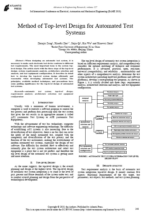
Method of Top-level Design for Automated TestSystemsZhenjie Zeng1, Xiaofei Zhu1,*, Shiju Qi1, Kai Wu2 and Xiaowei Shen11Rocket Force University of Engineering, Xi’an, China2Troops No. 96604, Beijing, China*Corresponding authorAbstract—When designing an automatic test system, it is necessary to make each electronic test device conform to different test requirements. The most important issue is the system top-level design. The article starts with the three steps of the top-level design: system requirements analysis, architecture selection and analysis, and test equipment configuration. It describes in detail how to develop the top-level system design efficiently and reasonably when developing automated test systems. The principles, available method techniques, and precautions have some guiding significance for the top-level design of automated test systems.Keywords—automatic test system; top-level design; requirements analysis; architecture selection; test equipment configurationI.I NTRODUCTIONUsually, with a minimum of human involvement, a computer is used to execute a software program to control the test process and perform data processing until the test system that gives the test results in an appropriate manner is called ATS (Automatic Test System) or ATE (Automatic Test Equipment). .With the advancement of test bus technology, computer technology and software engineering technology, the difficultyof establishing ATS systems is also increasing. Due to the diversification of test objectives, there is no bus that can cover the needs of the entire automated test, coupled with the complexity and diversification of the test process and the function of the test instruments, making the establishment of modern automated test systems, especially the design of test software. The difficulty has doubled. How to effectively and rationally plan the test system architecture and select test equipment is a place that is not yet perfect, and therefore the top level design of the automatic test system is getting more and more attention.II.T OP-LEVEL D ESIGNAs the name suggests, the top-level design is the overall planning and design at the highest level. The top-level design of automatic test system integration is to stand at the level of past, present and future demands of the system under test, and to conduct overall planning and design from the perspective of technological development.The top-level design of automatic test system integration is based on sufficient requirements analysis, and comprehensively considers the optimal matching of technical and economic performances. It is advanced, practical, open, real-time, universal (compatibility), and reliability. , maintainability and other aspects of a comprehensive analysis, determine the test system architecture (including hardware platforms and software platforms), develop a corresponding test program. As shown in Figure 1, it is usually divided into three steps: requirements analysis, architecture selection and analysis, and test equipment configuration.AemandanalysisArchitectureselection andanalysisTest equipmentselection andconfigurationFunctional AnalysisTarget signal typeMeasured parameter definitionTestability analysisTest method analysisInterface bus analysisHardware architecture analysisController selection and analysisHardwareplatformSoftware operating environment analysisOperating system selection and analysisDevelopment platform selection and analysisDatabase selection and analysisTest instrument (module) selectionUTT interface connection designSpecial parameters require processingSoftwareplatformFIGURE I. AUTOMATIC TEST SYSTEM INTEGRATION TOP LEVELDESIGN FLOWIII.D EMAND A NALYSISTest requirement analysis is the basis of automatic test system integration top-level design. It mainly contains five aspects: functional requirements of the test target, test parameters, test objects, test methods, and test system planning.3rd International Conference on Electrical, Automation and Mechanical Engineering (EAME 2018)A.Test Target Functional RequirementsThe different requirements of the test equipment working platform determine the test speed requirements, and also determine the different requirements of the online/offline test; the main control method and logic of the tested equipment determines the difference between the test procedures and methods; the input frequency of the tested equipment, Different parameters, such as amplitude and modulation method, determine the overall requirements for the operating frequency band, small signal level (minimum leakage), and waveform parameters of the automatic test system analog signal source; the output and content of the device under test determines the signal sampling of the automatic test system. The data acquisition method is different; the digital communication interface of the device under test determines that the digital communication interface that the automatic test system should have is different from the protocol; the testability interface of the device under test determines the final test capability and fault diagnosis ability of the automatic test system.B.Test ParametersThe test parameter analysis includes analysis: the form of the measured parameter (electrical or non-electrical, digital or analog, etc.), range and quantity; performance index (measurement accuracy and speed, etc.); the form and range of the excitation signal. In particular, when analyzing requirements for a top-level design of a general-purpose comprehensive automatic test system that is suitable for multiple systems, multiple protocols, and multiple equipment, comprehensive analysis is often required to integrate the test parameters.C.Test ObjectThe test objects vary widely. When analyzing the test objects, a comprehensive analysis must be performed in conjunction with the test system requirements of the test objects. In the face of a specific test object test system or subsystem, the description can use a variety of expressions to give different models of the test system at different levels of simplification, such as language descriptions, graphics, and mathematical formulas. As a simplified description of some test systems, their models merely express their basic characteristics, often ignoring irrelevant details in order to simplify their complexity. For a complex test object test system, a model is inevitably limited by some assumptions in its design and utility. These conditions often have some ambiguity and basically reflect an implicit conceptual idea. Therefore, when analyzing the requirements of a specific test object, it is usually necessary to establish a corresponding test system model.D.Test MethodsAccording to the functional requirements of the test target, a corresponding test method is formulated for the “face-to-face automatic test system” or “object-oriented automatic test system”.. E.Test System PlanningWhen developing an automated test system, it often takes a lot of time to complete the test-assisted tasks such as creating files and programming supporting test software. The test application software development platform can standardize all kinds of test processes and integrate an operating system that is suitable for various test and post-processing functions. It can help us to complete these test auxiliary work; therefore, we use this kind of test platform to conduct various tests. When testing, you can save a lot of time.IV.A RCHITECTURE S ELECTION AND A NALYSIS On the basis of sufficient requirements analysis, determining the architecture of the automated test system is the most critical step in the top-level design. That is how to determine the test plan from the perspective of the top-level design, and select the hardware platform and software platform architecture of the automatic test system, and the most important one is the selection of the test equipment digital communication interface bus.A.System Test Plan SelectionThe system test plan is the overall concept of product testing. It specifies the type of product testing, when (continuous or regular) testing, where (field or workshop, or which maintenance level), testing methods, and test methods used. The types of system test can be divided into: system-wide test and departmental system test, static test and dynamic test, online test and offline test, quantitative test and qualitative test, continuous test and periodic test, etc. The test level can be divided into three levels according to the location: production site, use site, and maintenance base. The test system (equipment) operating methods are generally:According to the use of the operation can be divided into three kinds of automatic, semi-automatic and artificial; according to the general degree of application can be divided into two kinds of special and general equipment; according to the association with the product can be divided into two kinds of BITE and external test equipment.Most of the test methods used in automated testing have so far been modeled on manual tests, from the measurement principles used, the testing techniques used, to the test procedures performed, except that computers were used instead of manual operations. As far as the characteristics and potential of automatic testing are concerned, fundamental reforms of the test plan are needed for future research.B.Selection of Test Equipment Digital CommunicationInterface Bus and ATS StructureThe development of automatic test systems has promoted the continuous emergence of various general-purpose test equipment interface buses and rapid technological advancement: from the early GPIB, CAMAC to the recent VXI, MXI, PCI, PCIe, PXI, PXIe, cPCI, MMS, IEEE1394 ( Firewire), USB, etc. Although technical characteristics are not the same, they are widely used.The structural elements of a modern automated test system are programmable test instruments, test controllers, interconnected standard digital interfaces, and software systems. At present, modern automatic testing has been widely used, and the test objects faced are large, complex, and diversified, making it impossible for an automatic test system based on any kind of bus technology to cover the needs of the entire test object.Multi-bus fusion automatic test system structure shown in Figure 2. It consists of test instruments, DUTs(design under test) and UUT(unit under test) interfaces, test controllers (computers), various general-purpose digital interface buses, and test software. The test controller is interconnected with the test instrument through the digital interface bus, and the device under test is connected to the input/output terminal of the test instrument through the UUT interface. The digital interface bus used may be GPIB, VXI, PXI, LXI, or even an internal computer bus (AT/EISA/PCI), or their convergence. Once the standard digital interface bus architecture used is determined, the automatic test system architecture is basically selected. In an automatic test system, regardless of the interface bus architecture, an external computer or built-in computer system can be selected as the test system controller. The choice of the test system controller should fully consider the optimal matching of technical and economic performance, and choose from real-time, practical, reliable, flexible and convenient.CAT test hostMaster control computerGPIB instrument PC card typeinstrumentVXIinstrumentPXIinstrumentUUT interfaceUUT……FIGURE II. MULTI-BUS FUSION AUTOMATIC TEST SYSTEMSTRUCTUREC.Test Software Platform Mode SelectionIn modern computer-based automated test systems, hardware is the foundation and software is the soul. Test software has increasingly become the main body of ATS, which determines the advanced nature, reliability, practicality, and real-time performance of the entire automated test system.The automatic test software platform mainly refers to the programming language and software support environment involved in the test application software design. It is an integrated software platform such as a computer operating system, a test programming language, a database software, and a program diagnosis software. The key element is Test programming language. Since the automatic test system was popularized and applied, there have been great developments in testing programming languages from low-level to high-level, to the current test application development environment.V.T EST E QUIPMENT C ONFIGURATION After the system structure of the test system is determined, the next task is to synthesize the test contents according to the requirements analysis, and to match the corresponding test equipment according to the test content requirements. There are three types of optional test equipment: general test equipment, special purpose equipment, and test interface adapter.A.Universal Test EquipmentThe universal test equipment includes a main box, a test controller, a main control interface, a zero slot controller, an instrument module, and a desktop instrument. The following factors should be considered when selecting the type of equipment: (1) The higher the degree of equipment automation, the shorter the time for detecting and isolating faults, and the less the manpower consumption, but the cost of test equipment will increase and more protection is needed. (2) Differences in capabilities between the two are to be considered when selecting a BIT (Built-in-Test) and an off-board automatic test equipment. (3) When the BIT is used in conjunction with the off-board automatic test, make full use of the BIT capability of each unit under test. (4) When selecting a dedicated or general-purpose device, it is necessary to consider that the special-purpose device is simple and convenient to use and has high efficiency, but the use range is narrow. (5) The main selection of instrument and equipment is based on the requirements of test parameters, characteristics of the signal to be measured, and range selection. When selecting the instrument module, pay attention to the size of the bus module, power, and number of slots.B.Special Purpose EquipmentWhen the test is not ready for selection, in addition to the above-mentioned common tests, when preparing for the following situations, it may be considered to develop or develop special purpose instrument (module) equipment. When the current product can not meet the test requirements, multiple instruments and equipments are required to complete the measurement together. However, the utilization rate of each instrument is very low or can be accomplished with one instrument. When the price is high and the utilization rate is low, the use of development or development is considered. Special purpose instrument.C.Test Interface Adapter DesignFor different test objects, the extraction and feeding of various test signals requires the design and manufacture of various test interfaces and special fixtures. In the automatic test system, especially the automatic test system assembly of complex electronic equipment, the requirements of the same type but different models and different test objects existuniversally, and often require the test system group to build a relatively universal automatic test platform. Through this platform, different test modules and test methods can be used to quickly and easily complete the automatic test system set-up (configuration) task for different test objects; however, the test interface and the dedicated test module cannot be matched and can only be tested according to the device under test. The test requires the development of a test interface adapter.VI.C ONCLUSIONThis article starts with the three steps of the top-level design: system requirements analysis, architecture selection and analysis, and test equipment configuration. It describes in detail how to perform top-level design efficiently and reasonably when developing automated test systems, and analyzes what the design must follow. Principles, methods, techniques, and precautions have certain guiding significance for the top-level design of automated test systems.R EFERENCES[1]LI Xing-shan, ZUO Yi, SUN Jie. Automatic Test System IntegrationTechnology[M]. Publishing House of Electronics Industry, 2004.[2]QIN Hong-lei, LU Hui et al. Automatic Test System. Beijing: HigherEducation Press, 2007[3]LIU Si-jiu, ZHANG Li-yong. Automatic Test System and VirtualInstrument. Beijing: Publishing House of Electronics Industry, 2009 [4]GU Zhi-yong, TENG Peng, HU Shi-guo, et al. Top-level design of ATSoverall plan for integrated helicopter display systems[J]. Electro-optics and Control, 2008, 15(11):59-62.[5]GU Ya-ping. Research on Top Design of VXI Bus TestingTechnology[J]. Electronic Testing, 1998(8):22-23.。
2024版年度UCP600

Disclaimer and Exceptions
2024/2/2
01
UCP 600 rules apply only to the relationship between banks and not to the underlying transaction.
02
Banks are not responsible for the accuracy or authenticity of the documents they handle.
03
Providing necessary documents and information.
04
Paying the required fees and charges.
2024/2/2
8
Beneficiary process
01
Receiving and reviewing the letransactions.
16
The impact of UCP600 on international trade
2024/2/2
Increased efficiency
UCP600 streamlines the process of handling documentary credits, which helps to increase efficiency and reduce the time and cost associated with international trade transactions.
risk associated with extending credit to importers and exporters. This, in turn, helps to promote
Universal Robots UR3机器人产品说明书

vSOURCEShttps:///media/1528658/tuv-nord-certificate.pdf • https:///media/1528658/tuv-nord-certificate.pdf https:///about-universal-robots/news-centre/universal-robots-welcomes-the-new-technical-specification-on-collaborative-ro-bot-design/ • Positive Impact of Industrial Robots on Employment – International Federation of Robotics • A Future That Works: Automation, Employment AndProductivity – McKinsey Global Institute • The Impact of Robots on Productivity, Employment and Jobs – International Federation of RoboticsThe Talent Challenge: Harnessing The Power Of Human Skills In The Machine Age – PriceWaterhouseCoopers • https:///products/ur3-robot/ • https:///products/ur-robot-benefits/ • https:///case-stories/continental/ • https:///applications/ • https:///case-stories/bj-gear/ • https:///case-stories/multi-wing/5 Myths DebunkedCOBOTS:Cobots are not dangerous. They have built-in safety functions that permit them to work safely side-by-side with people. Cobots do not need to be caged upbehind protective fencing (subject to risk assessment).7FixedSafety FunctionsEmergency Stop Interface Safeguard Stop InterfaceSystem Emergency Stop OutputRobot Moving Digital OutputRobot Not Stopping Digital OutputReduced Mode Digital Output Not ReducedMode Digital OutputCobots are dangerous!Myth #1Myth #2Myth #3Myth #4Myth #52,000,000jobs globallyRobots will createup toFROM 2017 – 202050%productivitywithout job lossesWith cobots,plan onincreasing headcountdespite increase in automationof CEOs52%10%Onlyfully automatableof jobs areRobots create jobs — better jobs. They relieve workers from strenuous and repetitive tasks so that workers can take on new roles. Ultimately, human dexterity, critical thinking, decision making and creativity cannot be replaced by machines.Robots replace jobsCobots are easy to implement, operate and upkeep. Being compact and lightweight, there is no need to change production layout when switching the cobot between tasks. They are easily programmed or re-deployed, and require minimal maintenance.11KGCobot arms weigh as little asAverage Setup Time0.5DAYSTime to switch between tasks fell from 40 minutesto 20 minutes.A producer of car instrument panels, deployed UR10 cobots to handle PCBboards and components.AT CONTINENTAL AUTOMOTIVE IN SPAIN50%Changeover timeIt’s a hassle to implement and maintain robotsRegardless of the scale of output cobots can be deployed for simple processes that are repetitive, manual, or potentially strenuous for workers.Simpleautomated tasksPick- and-place Packaging & palletisingScrew- drivingGluing, dispensing & weldingRobotics automation is for complex,large-scale operations1YEARAverage payback period as short asup to20%production cost/unitA manufacturer of axial fan solutions, installed a UR5 robot toits production line reducingAT MULTI WING IN CZECH REPUBLICRobots are costly!Cobots are cost effective. Installation requires minimalinvestment as they do not require major infrastructural changes.They can be redeployed to different functions in the production line, and used around the clock.The safety system is certified by TÜV Nordto Performance level D, resulting inan extremely reliable system13849ISO8Adjustable Safety LimitsJoint TorqueLimitJoint PositionLimitJoint SpeedLimitTCP Speed LimitPower LimitTCP Force LimitTCP Pose LimitMomentumLimit15066ISOUniversal Robots’ cobots meet the guidelines set out in ISO/TS 15066 which help integrators assess risks and requirements duringinstallation。
中考英语交通工具改进单选题50题
中考英语交通工具改进单选题50题1. We need to improve the ____ of our cars to reduce fuel consumption.A. speedB. performanceC. sizeD. color答案:B。
本题考查交通工具性能相关词汇。
选项A“speed”指速度;选项B“performance”有性能的意思,符合语境,强调汽车整体性能的提升以降低油耗;选项C“size”指尺寸;选项D“color”指颜色,均与降低油耗的性能改进无关。
2. The new technology can greatly enhance the ____ of the buses.A. safetyB. comfortC. beautyD. cost答案:A。
本题围绕交通工具性能改进。
选项A“safety”意为安全,新技术能提升公交车的安全性;选项B“comfort”指舒适;选项C“beauty”指美观;选项D“cost”指成本,而题干说的是新技术对公交车性能的提升,安全性能更符合。
3. To make the trains more efficient, we should focus on improving their ____.A. enginesC. seatsD. lights答案:A。
本题考查火车性能改进的重点。
选项A“engines”指引擎,改进引擎能使火车更高效;选项B“windows”指窗户;选项C“seats”指座位;选项D“lights”指灯光,这三个选项都不是影响火车效率的关键因素。
4. The improvement of the ____ can make the planes fly longer distances.A. wingsB. cabinsC. enginesD. pilots答案:C。
本题关于飞机性能改进。
选项A“wings”指机翼;选项B“cabin”指机舱;选项C“engines”指引擎,改进引擎能使飞机飞得更远;选项D“pilots”指飞行员,飞行员不是飞机能飞更远的直接改进因素。
美国软体家具阻燃性法规和标准体系概述

国际研究美国软体家具阻燃性法规和标准体系概述■ 司银平 王红强 王林婉(广东产品质量监督检验研究院)摘 要:本文详细阐述了美国软体家具阻燃性法规及其标准体系。
对美国软体家具阻燃性法规进行了概述,并重点论述了法规16 CFR Part 1633、16 CFR Part 1632和16 CFR 1640的适用范围和测试要求等,分析了美国家具标准体系的特点并列举了主要的ANSI软体家具阻燃标准,最后指出了美国软体家具阻燃性法规和美国家具标准体系的优缺点。
为软体家具出口企业进行产品设计开发提供指导意见,并为我国日益完善的家具标准体系提供一些借鉴。
关键词:美国,阻燃,软体家具DOI编码:10.3969/j.issn.1002-5944.2023.17.043Overview of Regulations and Standards System of Upholstered FurnitureFlame Retardant in the U.S.SI Yin-ping WANG Hong-qiang WANG Lin-wan(Guangdong Testing Institute of Product Quality Supervision)Abstract:The paper elaborates on the technical regulation and standards system of upholstered furniture fl ame retardant performance in the U.S. in detail, provides an overview of US regulations of upholstered furniture fl ame retardant ,with a focus on regulations 16 CFR Part 1633, 16 CFR Part 1632, and16 CFR 1640. The paper analyzes characteristics of the US standards system for upholstered furniture and the main ANSI standards for upholstered furniture fl ame retardant. Finally, the paper points out advantages and disadvantages of US regulations and standards system for upholstered furniture fl ame retardant, in order to provide guidance for Chinese upholstered furniture export enterprises to design their products, and provide reference for the increasingly perfect furniture standards system in China.Keywords: the U.S., fl ame retardant, upholstered furniture0 引 言美国是世界上技术法规比较健全和完善,并且标准化工作发展最早的国家之一。
PF6 FlexSystem产品说明书
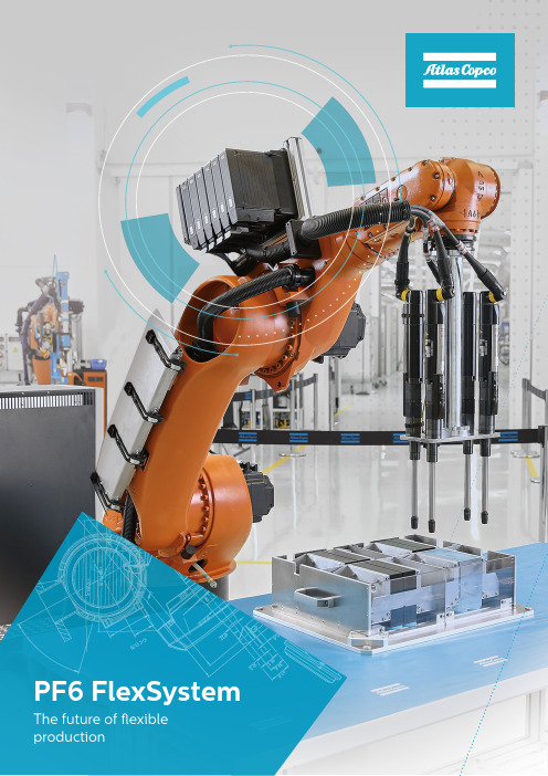
4
Easy system integration
A modular PF6 FlexSystem reduce your engineering e orts, making the integration with line equipments easier and e ective .
Improve your safety, while eliminate multiple cables and increase reliability and MTBF without worry about dirt or wet environments.
Result data collection
Operator guidance
PROFIsafe
IP 54
What customer are saying?
“I saved two whole installation days using the PF6 FlexSystem. The product is extremely fast and smooth. I also saved seven seconds in cycle times.
In conjunction with the most durable
Application Centers have the ability to combine standard Atlas Copco acessories to innovate a customized solution, such as a torque arm, wheel multiple, and more.
PF6 FlexSystem
The future of exible production
交通运输标准国际化现状与实施路径研究
学术研讨交通运输标准国际化现状与实施路径研究■ 潘 硕 张 宇 王 冀(交通运输部科学研究院标准与计量研究中心)摘 要:近年来,世界发达国家积极实施标准化战略,增强标准国际化与标准化战略的融合度和协调性。
为提升我国交通运输行业标准国际化发展水平,开展了交通运输标准国际化现状与实施路径研究。
首先,通过问卷调研了我国交通运输行业相关标准化组织机构参与国际标准制修订和国际标准化组织工作的情况;结合政策调研及案例分析等方式,总结行业标准化机构在标准国际化工作当中存在的问题;最后,在总结分析部分发达国家标准国际化政策措施的基础上,对比行业标准国际化发展现状及存在的问题,提出适应于我国交通运输行业标准国际化发展水平的实施路径和具体举措。
关键词:标准国际化,国际标准化,标准制修订,标准化战略DOI编码:10.3969/j.issn.1002-5944.2021.05.005Research on Status and Implementation Path of Internationalization ofTransportation StandardsPAN Shuo ZHANG Yu WANG Ji(Standardization and Metrology Research Centre, China Academy of Transportation Sciences)Abstract: In recent years, the developed countries in the world have actively implemented the standardization strategy to enhance the integration and coordination of the internationalization and standardization strategies. In order to improve the international development level of China's transportation industry standards, the status quo and implementation path of transportation standards internationalization were studied. Firstly, the participation of relevant standardization organizations of China's transportation industry participating in the development and revision of international standards and the work of international standardization organizations was investigated through questionnaire; Combined with policy research and case analysis, this paper summarized the problems existing in the standardization work of industry standardization institutions; Finally, on the basis of summarizing and analyzing the policies and measures of standards internationalization in some developed countries, this paper compared the development status and existing problems of industry standards internationalization, and put forward the implementation path and specific measures suitable for the internationalization development level of transportation industry standards in China.Keywords: Standard internationalization, international standardization, standard formulation and revision, standardization strategy基金项目: 本文受交通运输标准国际合作交流发展战略研究项目(项目编号:2020-99-053)资助。
Countermeasures for Integrated Delivery of Aviatio
Countermeasures for Integrated Delivery of Aviation Product Project ManagementGuang ChenAVIC Research Institute (Yangzhou) science and Innovation Center Abstract: With the deepening of China’s enterprise reform, China’s manufacturing, including aviation products, is facing unprecedented opportunities for development. Starting from the characteristics of aviation product project management, this paper analyzes the difficulties in the integrated delivery of aviation product project management, including the lack of strong market organization and management institutions, unclear delivery operation mechanism, and the need to optimize the management rules of integrated delivery of project management. Finally, it is the establishment of countermeasures for integrated delivery of aviation product project management, starting from strengthening the market organization and management institutions, improving the delivery operation mechanism and the operational efficiency of management rules in three areas, so as to promote the level of integrated project delivery of aviation product project management. Keywords: Aviation Products; Project Management; Integrated Delivery; Countermeasures; ProblemsDOI: 10.47297/taposatWSP2633-456906.202102011. IntroductionWith the deepening integration of military and civil products in China, project integrated delivery mode has begun to be applied in aviation products. IPD means Integrated Project Delivery. In 2007, the California Board and the American Academy of Architects jointly issued the IPD Guide, which defines IPD as: “Integrating systems, human resources, practices and enterprise structures as a unified process, through collaborative platforms, making full use of the insights and talents of all participants, through joint efforts at all stages of design, construction and operation, to optimize the results of construction projects, maximize benefits, increase the value of owners and reduce waste.”2. Characteristics of Aviation Product Project ManagementAviation product project management has its own characteristics. Unlike commercial products, aviation products are mostly military products, and are mostly produced and sold by state-owned enterprises in China. Aviation manufacturing industry is a highly integrated modern science and technology with high access threshold, great industrial driving effect, high correlation between upstream and downstream, and strong radiation. Innovating the system and mechanism of China’s aviation manufacturing industry, exploring the establishment of “main manufacturer-About the author:Guang Chen (1986-10), Male, Nanjing, Jiangsu, Han nationality, Scientific research department,senior engineer, master, aviation industry.Theory and Practice of Science and Technologysupplier” model and cultivating qualified suppliers are one of the important means and ways to promote the rapid development of China’s civil aviation manufacturing industry. The procurement and supplier management of aviation manufacturing industry is changing from the traditional product-centered organization mode to the Internet, open and collaborative customer-centered organization mode. In the process of changing the organization mode, a unified standard, process and platform are gradually established. The project management of aviation products involves many production project units, and the requirements for product quality and specifications are high. Therefore, higher requirements are put forward for the management of different cooperative units.3. Difficulties in Integrated Delivery of Aviation Product Project Management(1) Lacking of strong market organization management institutionsAs a buyer of aviation products, it is necessary to integrate downstream and upstream industries as well as production and marketing management units, in particular by building a strong organizational structure capable of ensuring that production requirements and standards are fully implemented in the production chain and transportation and operation. At present, China’s aviation products have achieved integrated delivery in project management, but the level of integrated delivery is low, and the responsibility of the company’s project management organization is unclear, resulting in the overall low product delivery efficiency. In the past, in the process of product delivery, although each department has a unified delivery goal, but the focus of its department is too concentrated on the interests of each department itself, rather than focusing on the overall goal of the enterprise, resulting in a serious waste of resources.(2) Unclear delivery operation mechanismDelivery mechanisms are more about integrating delivery operational aspects. The production units of aviation products are mostly state-owned enterprises, and even a considerable part is military enterprise. Due to the particularity of unit property, in terms of management architecture, the production, manufacturing and assembly and transportation of products involve different subjects including military, civil, commercial enterprises and state-owned enterprises, and how the structures of different subjects are connected, such as the holding of consultation meetings, team building, and the establishment of personnel incentive system. If these operation mechanisms cannot be clarified, they will also cause trouble for project integrated delivery.(3) Management rules of project management integrated delivery need to be optimizedAt present, in the process of management, some enterprises have made systematic changes to the original production management mode, and the personnel management mode is also flexible. However, some state-owned enterprises are restricted by institutional factors, and there is no flexibility of commercial enterprises in the development and reform of enterprises. Therefore, in the process of docking different subjects, the highly informationized management system of commercial enterprises, including the informationization of financial system, personnel management and material storage, has reached a high level. If the delivery management rules are not optimized in the process of integrated delivery, it is easy to cause low efficiency of delivery management.Vol.2 No.1 2021 4. Integrated Delivery Strategies for Aviation Product Project Management(1) Strengthening market organization management institutionsIt can be seen that aviation products themselves have certain particularity, and their requirement in terms of accuracy and quality are high, which requires strong organizations to control the quality. Enterprises should establish an integrated delivery management agency with relevant affiliated units to ensure that all production cooperation units and affiliated enterprises within the enterprise can accurately convey information and effectively control all aspects. In the process of management, it focuses on breaking the barriers of interests between different departments to ensure the optimization of overall efficiency. The information of product delivery and financial communication are realized in a unified platform to maximize the efficiency of integrated delivery management.(2) Improved delivery mechanismThe project integrated delivery of aviation products needs to sort out the systems and structures of different subjects, build an efficient information communication system, form an organic unity of different product production departments, and integrate different management systems. Military production units should further adapt to the current market competition rules and quickly integrate into commercial competition. In team building and the establishment of incentive system, we should further improve the incentive effect and introduce the positive factors in the market mechanism into the production and delivery of commodities. Incentive differences in projects should be suitable for different participants, and cannot affect the enthusiasm of the overall project operation because of the large incentive differences. In human resource management, it is necessary to introduce more high-quality talents adapting to the rhythm of market competition to ensure the efficient integrated delivery of projects. In the process of cooperation, different subjects should participate in depth until the whole project can be successfully completed, fully communicate in cooperation, timely adjust, and ensure that all parties’ wishes can be effectively expressed. In the process of communication mutual benefit should be achieved, and ultimately maximizing the interests of all parties.(3) Increasing the efficiency of management rulesThe delivery management of aviation products should adapt to the management mode of different management subjects, further optimize the management rules and improve the efficiency of docking. Therefore, aviation product manufacturing units need to further integrate their own information management level, in order to achieve deep docking with commercial enterprises. At the same time, aviation product production units also need to vigorously introduce talents, and transform the talent advantage into product advantage to improve the quality of aviation products. In the process of management, it is inevitable to encounter various emergencies and irresistible factors. The above abnormal conditions will affect the delivery of products. By improving the operation efficiency of management rules and building a multi-level disposal system in a timely manner, the impact of various emergencies and abnormal conditions can be minimized to ensure the delivery of products with quality and quantity.5. ConclusionThe integrated delivery of aviation products needs to further optimize and perfect the organizational structure and operation management mechanism of all parties to ensure thatTheory and Practice of Science and Technologythe links in the delivery process can be effectively connected. Starting from the characteristics of aviation product project management, this paper analyzes the difficulties in the integrated delivery of aviation product project management, including the lack of strong market organization and management institutions, unclear delivery operation mechanism, and the need to optimize the management rules of integrated delivery of project management. Finally, in terms of the formulation of strategies of the aviation product project management integrated delivery, it can be processed from strengthening the market organization and management institutions, improve the delivery operation mechanism and improve the efficiency of management rules in three areas to improve. At the same time, it can be seen that the delivery of aviation products needs to keep pace with the times, improve the adaptability of product production and further enhance the market competitiveness of products through in-depth docking with the market operation mechanism.References[1] Yin Yilin, Liu Yanhui. “Research on Integrated Management Mode of Large-scale Construction ProjectsBased on Project Group Governance Framework” [ J ].Soft Science, 2009,23 ( 08 ) : 20-25.[2] Xu Rui, Xia Yan, Sun Wenzhi.”Research on Product Data Management and Project Management Integra-tion” [ J ].Aerospace Precision Manufacturing Technology, 2016,52 ( 01 ) : 50-52 + 62.[3] Zhao Jun, Deng Jian. “The Significance of Integrated Management of Subprojects for the Success of Engi-neering Projects” [ J ]. Project Management Technology, 2017,15 ( 09 ) : 116-19.[4] “The Application of Multi-project Management System in the Development of New Aviation Products” [ J ].Project Management Technology, 2020, 18 ( 07 ) : 126 – 30.[5] Xu Jiaojiao. “The Application of Key Indicators in the Pre-trial Production Project Management of NewModels” [ J ]. Time Automobile, 2019 ( 11 ) : 4 – 6.[6] Chen Qi. “The Exploration of Supplier Management Mode for Aviation Product Development Project” [ J ].Modern Commerce, 2019 ( 17 ) : 125-26.[7] Ren Tianhao, Wu Xiuyuan, Zhong Haifeng. “Research on Efficient Collaborative Model of Complex ProductR&D Projects” [ J ]. Project Management Technology, 2018,16 ( 08 ) : 34-37.。
核黄素测试国际标准(德国)
Information sheetRiboflavin testfor low-germ or sterileprocess technologies Fluorescence test for examination of cleanabilityFor food, aseptic, pharmacy and chemistryContents1.Introduction (3)2.Scope (3)3.Terms, definitions (3)4.Aim of the fluorescence test (4)5.Instatallation, equipment, specifications and carrying out the test (5)5.1General notes and points to be observed (5)5.2Test build-up (5)5.3Test equipment and specifications (5)5.3.1Test solution (5)5.3.2Water used to prepare the test solution (6)5.3.3Cleaning water (6)5.3.4Darkening (6)5.3.5Inspection lamp (UV lamp) (6)5.3.6Surfaces to be examined (6)5.3.7Pre-cleaning (6)5.3.8Adjustment of components (6)5.3.9Spray balls/nozzles and fittings (6)5.3.10Pressure and flow rate measurement (6)5.3.11Cleaning procedure (6)5.4Carrying out the test (7)6.Evaluation of the fluorescence test (7)7.Documentation of the fluorescence test (8)7.1Documentation of fluorescence test before carrying out the test (8)7.2Documentation of fluorescence test during carrying out the test (8)7.3Documentation of the fluorescence test after carrying out the test (8)8.Annex (9)8.1Ingredients and recipes of test solutions (9)8.2Schematic sketch of an installation for carrying out a fluorescence test (10)This publication has been prepared by the "Riboflavin Test" Working Party of the Sterile Process Engineering Group of VDMA. It is available as a downloadable file under/verfahrenstechnik. Suggestions for improvements and additions can be sent to the address below.VDMAVerfahrenstechnischeMaschinen und ApparateLyoner Str. 1860528 Frankfurt am MainTelephone +49 69 66 03-1432Fax +49 69 66 03-1421E-mail vtma@Internet: /verfahrenstechnik1.IntroductionTests for examination of cleanability play a major role in sterile process technology. A variety of tests are applied in practice, depending on the respective use case, suitability or requirements. This information sheet does not specify further details in this respect. The described fluorescence test is first and foremost suitable for the components named in the scope, as far as these can be examinated by means of visual inspection. This being the case, the fluorescence test is not intended to replace other well-established tests, but rather to supplement available possibilities in this sector.The objective of this information sheet is to provide manufacturers, suppliers and users with a document that can simplify the accord, planning, carrying out and documentation of a fluorescence test. In doing so, the information sheet summarizes different tests commonly used in practice as well as comprehen-sive experience gathered with these tests to provide a possible coarse of action. Manners of procedure or accords that deviate in part or completely are, however, expressly possible.2.ScopeThe scope of this information sheet covers components, apparatuses, machinery and plants (also re-ferred to in this information sheet as ‘components’) for low-germ or sterile process technologies with high or highest requirements regarding cleanability, as far as these are accessible for visual inspection.These components are used in the food, aseptic processing, pharmaceutical and chemicals sector, e.g.vessels, reactors, filter equipment, pumps, agitators, centrifuges, pasteurizers, filling systems etc. includ-ing fittings and peripheral equipment.Note on use:This information sheet gives advices to the user. It is, however, incumbent upon the user of the informa-tion sheet to verify or consider requirements, the current validity thereof and necessary measures con-cerning the user’s concrete use case. This concerns in particular all laws, ordinances, directives etc. that could be relevant for the respective case of use.3.Terms, definitionso Fluorescence testTest using a fluorescent substance for examination of cleanability of components o CleanabilityComplete removal of the test solution by the cleaning medium under application of the selectedconditions with regard to the cleaning elements, cleaning process or the design of the compo-nento Cleanability testTest for complete cleanability under the conditions selected for the fluorescence test o Weak point testTest for localizing critical points;Usually parameter values of the cleaning procedure are used which deviate from those of thecleanability test (reduced pressure or throughput of the cleaning medium or duration of clean-ing process)o Optimization testStepwise optimization and testing of the suitability of new parameter values through separate,new cleanability testso Test solutionSolution for carrying out the fluorescence testo CIP cleaningCleaning of components in assembled condition (Cleaning In Place)o Cleaning waterWater for cleaning the component being examinedo Fully demineralised waterFully desalinated water;also referred to Aqua purificata (AP) or Purified Watero WFI waterWater For Injectiono Critical pointsPoints that are difficult to clean and can be cleaned completelyo Non-critical pointsPoints that are easy to clean and can be cleaned completelyo Non-cleanable pointsPoints that cannot be cleaned completelyo Cleaning elementElement for targeted application of cleaning liquid to the component to be examined;Examples of cleaning elements: spray ball, rotating jet cleaner, cleaning nozzle, spray lance o Surfaces to be examinedAreas of the component being examined that are to be accounted for in the fluorescence test o Surfaces to be wettedSurfaces to be examined on which the test solution is to be appliedo Carrying out the testApplication and removal of the test solution as well as the subsequent inspection for remainingfluorescenceo Workplace limit value1Limit for the time-dependent average concentration of a substance in the air at the workplace, inrelation to a given reference period.4.Aim of the fluorescence testThe fluorescence test described in this information sheet is for the examination of cleanability. This is carried out by the examination of the basic accessibility to, as well as the complete wetting of all areas in which a verification of cleanability through the cleaning medium is required.The cleanability test is aimed to verify complete cleanability; the result of the test is a qualitative state-ment. In addition to this, the step-by-step or repeatedcarrying out of the fluorescence test also enables qualitative statements or examination of measures for improving or optimizing the cleaning process.Table 1 specifies the goals that can be achieved with the fluorescence test:Fluorescence test: Aim of the test: Criterion of quality after the test:Weak point test Localizing critical points;provided as optional pre-liminary stage to thecleanability test. - Visible fluorescence2 at critical points (acc. definition in Clause 3); these are to be con-firmed through a cleanability test.Cleanability test Verification of fullcleanability.- No visible fluorescence2.Optimization test Stepwise optimizationand checking of suitabil-ity of new parametervalues through separate,new cleanability tests. - No visible fluorescence2.- Improved parameter values (e.g. reduced wa-ter consumption, shorter cleaning time)Table 1: Achievable goals using fluorescence test acc. to information sheet1 Specifies the concentration of a substance at which acute or chronical health implications are generally not to be expected. Defi-nition from Hazardous Substance Ordinance of December 23, 2004 (BGBl. (German Federal Law Gazette)I P. 3758, 3759), last amanded through Article 4 of the Ordinance of March 6, 2007 (BGBl. I P. 261)2When checking the surfaces being examined for any fluorescence by means of visual inspection using a UV lamp.5.Instatallation, equipment, specifications and carrying out the test5.1General notes and points to be observedRegulations and directives relating to occupational health and safety must always be observed when carrying out the test. Furthermore, special reference is made to the following:o Testing personnel:No specific requirements are placed with regard to the education of testing personnel. Testingpersonnel should, however, be suitably and trained to carrying out the test or guided by in-housework instructions.o UV lamp:The use of a UV lamp can cause damage to eyes through penetrating UV rays. It is therefore nec-essary to wear safety goggles and to observe any additional protection measures specified bythe manufacturer of the UV lamp.o Occupational safety:As the UV lamp is always used in a moist environment personal fuse protection of the electricalsupply should be provided, e.g. using isolating transformers3. If it is necessary to light up a vesselwith a UV lamp when carrying out the test and to enter a vessel, this precautionary measure isstrongly advised.o Degreasing agent:The safety data sheet of the supplier must be available and must be observed.o Fluorescent substance:The safety data sheet of the supplier must be available and must be observed.o Drying out:When completely dried there is no homogeneous thickness of the applied layer of fluorescentsubstance. Reproducible verification of the cleanability is not possible in this case. With partial orincomplete drying there is also no reproducible condition with regard to the removal or dissolv-ing of the fluorescent substance. Drying out of the test solution must therefore be avoided.5.2Test build-upThe test build-up for performing a fluorescence test can be carried out in compliance with the arrange-ment shown in Annex 8.2, Fig. 1.5.3Test equipment and specifications5.3.1Test solutionA test solution has to be prepared prior to carrying out the test. Table 2 in Annex 8.1 specifies Ingredientsand recipes of test solutions. These ingredients and recipes have proved their worth in fluorescence tests in practice and in trial carried out during the preparation of this information sheet.It is basically also possible to use other partially or completely deviating ingredients or recipes for the test. Deviations and the effect these may have are to be taken into account or arranged separately, if necessary.Note on recipes containing ethanol: Some recipes are used which require the addition of ethanol in wa-ter for the preparation of test solutions (for improved wettability, but also increasing the drying ten-dency). This can have an impact on the protection against explosion, occupational health and safety and must be considered separately, if necessary.According to calculations and assuming realistic conditions, it must be expected that the limit value for the workplace will be exceeded; the ethanol intake through inhaled air can cause a significant increase in the blood alcohol level (allowing for typical vegetative physiological values for breathing rate etc.). Under realistic temperatures it may also occur that the lower ignition limit of the ethanol air mixture in the gas phase is exceeded.If necessary, effects resulting from the use of recipes containing ethanol are to be accounted for through own observations, measurements and/or appropriate measures.3Isolating transformers transform applied electrical line voltages in the ratio of 1:1 to a winding with safe electrical separation (increased or doubled isolation to the system). They generate a non-earthed, free potential of the output voltage so that no current can flow through the body to earth upon contact. They are used for works on devices fed with line voltage to reduce the hazard of an electric shock.5.3.2Water used to prepare the test solutionThe quality of the water used for preparing the test solution should have at least the same quality as that of the cleaning water (see Clause 5.3.3). To avoid deposits of minerals such as lime, demineralized water should always be used as a minimum quality for preparing the test solution. The water for the test solution should be at room temperature.5.3.3Cleaning waterWater of at least drinking water quality is to be used as cleaning water. The temperature of the cleaning water is to be in the range of 12 — 25 °C. At temperatures lower than this, a decline in the cleaning result is to be expected.5.3.4DarkeningIt must be possible to darken the area of the surfaces to be examined; this only applies if the surfaces to be examined are not automatically in the dark due to their arrangement (e.g. on the inside of vessels).5.3.5Inspection lamp (UV lamp)A UV lamp is used to make the fluorescence of the test solution visible, safety notes in this respect are given in Clause 5.1. The common wavelength for UV lamps used for the fluorescence test is 365 nm.5.3.6Surfaces to be examinedSurfaces for exmaninations are usually the inside surfaces of a component being examined including fittings and, wherever cleaning elements are available for cleaning outer surfaces, also the correspond-ing outer surfaces.Note: To save time, it may be expedient when testing large, interconnected surfaces, not to wet all parts with the test solution. This can be the case, for example, with parts of large, interconnected surfaces of a vessel wall, as long as it can be assumed that these surfaces will react in the same way as the adjacent, fully wetted parts when cleaning off the test solution.Surfaces not to be wetted are still to be attributed to the surfaces to be examined and accounted for in carrying out the test and documentation.If parts of the surface to be examined are not to be wetted with test solution, this is to be arranged in advance and documented before carrying out the test.5.3.7Pre-cleaningThe surfaces to be examined must look clean and and be grease free.Note: If due to the design or operation it is not possible to make the surface completely grease free it must be taken into account that at these points there will be reduced adherence and consequently easier removal of the test solution. The wettability of these areas can therefore not be evaluated using the fluo-rescence test.5.3.8Adjustment of componentsThe component to be examined, e.g. a vessel or piece of equipment must be positioned as instructed. Any deviations are to be corrected or documented if necessary.5.3.9Spray balls/nozzles and fittingsSpray balls/nozzles in or on the component to be examined must be mounted in compliance with the specification (e.g. shop drawing, assembly instructions) of the component to be examined. For the clean-ing process all fittings required for the operation must be installed.5.3.10Pressure and flow rate measurementPrior to every connection of a spray ball/nozzle a pressure and flow rate measurement should be carried out (ideally required as standard). If this is not possible, the conditions at the individual sprayballs/nozzles must be calculated using the available data. The number, position and arrangement of pumps, pressure and flow rate measurements and spray balls/nozzles should therefore be outlined. (comp. Clause 7.1).5.3.11Cleaning procedureThe cleaning procedure for the test is carried out using cleaning water (see Clause 5.3.3). The duration of the actual cleaning process has to be adjusted to the actual degree of contamination during the later use.The cleaning procedure is usually specified by the supplier of the component being examined (e.g. com-plete vessel, equipment etc. including fixtures in compliance with Clause 2). In doing so, the aim of the fluorescence test (see Clause 4, Table 1) is to be observed. The specification for the cleaning procedure should contain details ono duration,o pressure,o flow rate ando sequenceof the cleaning element application. It should also contain details ono filling levels of the component ando valve positions as well aso positions and/or movement/speed of rotation of the component’s active elements.A suitable cleaning procedure may involve the application the cleaning elements or element-free con-nections with water, or the movement/speed of rotation of moving elements in or through cleaning water. Beyond this, an appropriate cleaning procedure can also comprise a random combination thereof.5.4Carrying out the testNotes:Before carrying out the test it is important to observe the points described in Clauses 5.1, 5.2 and 5.3.The documentation prior to performance of the test is described in Clause 7.1.Carrying out the test:1.Apply test solution to surfaces to be wetted using an atomizer nozzle. The surfaces to be wettedmust be wetted completely.As an alternative the surfaces to be examined can also be wetted with test solution through flood-ing and subsequent emptying of the component being examined. When flooding, always make sure that the component can be completely flooded.2.Bring component to be examined into correct operating condition.3.Carry out the cleaning procedure described in Clause 5.3.11.4.Visually inspect the surfaces to be examined for detectable fluorescence using a UV lamp.6.Evaluation of the fluorescence testThe fluorescence test is considered as successfully passed when the criterion of quality described in Table1 is met after completion of the test.If the cleanability test for the component being examined is failed, the cause of this failure must be de-termined. The test is then repeated after correction measures have been carried out (e.g. modification of the cleaning procedure) and possibly coordination with the client. The new test conditions must be documented.When carrying out the weak point test it may occur that it is not the associated criterion of quality that is met, but rather that of the cleanability test. In this case, it is recommended to mutually acknowledge the weak point test as cleanability test.7.Documentation of the fluorescence testThe following listed items are to be documented:7.1Documentation of fluorescence test before carrying out the testa)Test build-upo Description, sketches/shop drawings, or pictures of the installationo Wavelength of used UV lampb)Component to be examinedo Designation of the component to be examinedo Drawing number (possibly revision number) of the component to be examinedo Serial number or factory number of the component to be examinedo Just when some parts are not to be wetted with test solution: surfaces to be examined (comp. 5.3.6; if necessary using drawings or sketch diagrams to specify)c)Measuring devices and reference measuring devices used for the testo Name and test equipment number of the used reference measuring deviceso Calibration protocols of the used measuring equipmentd)Test solution/cleaning watero Quality of water used to prepare test solutiono Temperature of water used for preparing test solution (room temperature: yes/no)o Recipe of the used test solution (see Annex, Clause 8.1)o Quality and temperature of cleaning water (see Clause 5.3.3)7.2Documentation of fluorescence test during carrying out the testa)Description of test in compliance with Table 1 (e.g. "weak point test")b)Cons. number of testc)Date, test begins (time of day)d)Confirmation 'test solution fluorescing’e)Confirmation that surfaces to be wetted have been completely wetted with the test solution, orthe component has been completely filled with test solutionf)Confirmation ‘component is in correct operating condition'g)Start of cleaning procedureh)Application of cleaning elements, if applicable:o durationo pressureo flow rateo sequencei)Filling levels of the component, if applicablej)Valve positions, if applicablek)Positions and/or movement/speed of rotation of active elements of the component, if applicable l)End of cleaning procedurem)Carrying out and result of visual inspection using a UV lamp7.3Documentation of the fluorescence test after carrying out the testa)Date, end of test (time of day)b)Position and shape of critical points, if applicablec)Pictures of condition of the component being examined after completion of the test (optional)d)Evaluation according to Clause 68.Annex8.1Ingredients and recipes of test solutionsRecipe No.: 1 2 3Case of application: All components Only components that are com-pletely filled with test solution(flooded). Test for de-sign experi-ments, where critical points are difficult to defineRemark: Application of thetest solution canalready be identi-fied with the na-ked eye, solutionhas been sprayedon evenly; dryingof the test solution(compare Clause5.1) is avoided. Manual application of the testsolution is obmitted. Addition ofhydroxyethyl cellulose is there-fore also no longer necessary.With this recipe partially thinnerlayer thicknesses occur whenapplied by spraying. These layersare not adequately identifiablewith the naked eye, could lead toincorrect conclusions in the as-sessment of the cleaning result.The test solution is thereforeonly to be used for completeflooding.Increasedadhesion ofthe test solu-tion. Appro-priate forcases inwhich there isonly a narrowmargin be-tween adhe-sion and re-moval of thetest solution.Constituent / AdditionRiboflavin (dyes, increases vis-cosity and is fluorescent);CAS-No.: 83-88-50.2 g 0.2 g 1 gWater (serves as solvent andcarrier medium of the ribofla-vin); For requirementssee Clause 5.3.2.1000 ml 1000 ml 1000 mlHydroxyethyl cellulose ("HEC", for increasing viscosity and layer thickness); Requirements: normal type (not allyl modified),with swelling delay (reacts with delayed swelling), viscosity class: 100 000 mPas (in 1.9 % solution, 20 °C, 20°GH);Viscosity of applied HEC test solution: 50 -75 mPas Recommended(not absolutelyessential):5 g- 10gTable 2: Ingredients and recipes of test solutionsNote:Instead of riboflavin also uranin (CAS-No.: 518-47-8) can be used as fluorescent substance. With the same dosing, test solutions of both fluorescent substances are equally good when applied in the fluores-cence test.8.2Schematic sketch of an installation for carrying out a fluorescence testFig. 1: Schematic sketch of an installation for carrying out a fluorescence test© VDMA Process Plant and Equipment Association, English edition published: March 2008 Page 10 of 10 Information sheet 'Riboflavin test for low-germ or sterile process technologies'。
3GPP 5G基站(BS)R16版本一致性测试英文原版(3GPP TS 38.141-1)

4.2.2
BS type 1-H.................................................................................................................................................. 26
4.3
Base station classes............................................................................................................................................27
1 Scope.......................................................................................................................................................13
All rights reserved. UMTS™ is a Trade Mark of ETSI registered for the benefit of its members 3GPP™ is a Trade Mark of ETSI registered for the benefit of its Members and of the 3GPP Organizational Partners LTE™ is a Trade Mark of ETSI registered for the benefit of its Members and of the 3GPP Organizational Partners GSM® and the GSM logo are registered and owned by the GSM Association
主动安全软目标物标定系统研究

FRONTIER DISCUSSION | 前沿探讨1 前言随着社会经济的不断发展,人们的生活水平不断提高,汽车产品在人们生活中也扮演着越来越重要的角色,为大众的出行带来了极大的便利。
在当前形势下,汽车产业技术不断发展,人们不再仅仅满足于传统汽车带来的便利,对汽车产品提出了更高的要求,智能网联汽车的发展成为了汽车产业技术进步的焦点。
智能网联汽车相比于传统汽车具备诸多优势技术,成为了汽车产业发展的新动能,进一步提高了汽车产品的性能水平。
主动安全软目标物作为智能网联汽车测试装备链的关键设备之一,其性能的好坏直接关系到主动安全测试结果的准确度、可信度。
主动安全软目标物标定技术成为了制约目标物发展的关键因素之一[1-2]。
目前,国内对于主动安全软目标物的研究主要集中于软目标物产品的开发方面,对于软目标物标定技术的研究相对较少。
国内有部分研究机构、科技公司及高校已研制出部分软目标物,但对于其标定方法及手段的研究较少,这也是阻碍国产软目标物发展的主要原因之一。
随着智能网联汽车领域的不断发展,不断突破领域内高端设备关键技术,已成为未来汽车行业发展的趋势。
2 主动安全软目标物标定现状研究现阶段我国使用的主动安全软目标物主要依赖于从国外进口,软目标物的制备工艺、异构缝合、测试评价等核心技术被国外公司所垄断。
随着我国主动安全测试技术的发展,尤其是相关标准、规程的起草制定,使得针对主动安全软目标物的标定技术的研究变得尤为重要[3]。
目前,国内对于软目标物的标定技术处于探索阶段,还未形成成熟可用、行业认可的系列标定设备产品。
随着我国智能网联体系不断发展和完善,国外软目标物的产品系列已经不能完全满足国内主动安全测试技术发展的需求,掌握自主开发软目标物能力已经成为了国内主动安全测试领域发展的关键诉求,而软目标物的标定技术是自主开发软目标物测试验证评价的关节环节之一。
通过对ISO 19206系列标准进行研究,软目标物的标定主要分为:毫米波雷达RCS标定、红外反射特性标定、光学特性标定(RGB)、关节运动仿生特性标定、几何特性标定。
606se
606se1. IntroductionThe 606se is a revolutionary new product in the field of electronic devices. Designed with cutting-edge technology and innovative features, this device offers a wide range of functionalities that cater to the needs of modern users. In this document, we will explore the key features, specifications, and benefits of the 606se.2. Key Features2.1 Advanced ProcessorThe 606se is powered by a state-of-the-art processor that ensures fast and efficient performance. With its high processing speed, users can seamlessly multitask and run resource-intensive applications without any lag or delay.2.2 High-Resolution DisplayEquipped with a stunning high-resolution display, the 606se delivers crisp and vibrant visuals. Whether you are watching videos, playing games, or working on graphic-intensive tasks, the display ensures an immersive and enjoyable experience.2.3 Enhanced SecurityThe 606se prioritizes the safety and security of its users. It features advanced security mechanisms such as face recognition and fingerprint scanning, providing users with a secure and convenient way to unlock their device and protect their data.2.4 Dual Camera SystemCapture stunning photos and videos with the 606se’s dual camera system. The device is equipped with a high-resolution rear camera and a front camera with advanced beautification features, ensuring users can capture their best moments with exceptional clarity and detail.2.5 Long-lasting BatteryThe 606se boasts a powerful and long-lasting battery that allows users to stay connected and productive throughout the day. With its optimized power management system, the device ensures maximum battery efficiency, minimizing the need for frequent recharges.3. SpecificationsThe table below provides an overview of the key specifications of the 606se: Specifications DetailsProcessor Advanced 2.0 GHz octa-core processorDisplay 6.2-inch high-resolution OLED displayMemory 8GB RAM, 128GB internal storageOperating System Android 10Camera Rear: 12MP + 8MP dual cameras, Front: 20MP camera Battery 4000mAh4. Benefits4.1 Enhanced ProductivityWith its powerful processor, high-resolution display, and ample memory, the 606se is designed to enhance productivity. Users can effortlessly multitask, run productivity applications, and enjoy a seamless user experience.4.2 Immersive EntertainmentExperience immersive and vibrant entertainment with the 606se’s high-resolution display and powerful audio capabilities. Whether you are streaming videos, playing games, or listening to music, the device offers a captivating experience.4.3 Secure and ConvenientThe 606se prioritizes user security and offers convenient security features such as face recognition and fingerprint scanning. Users can unlock their device and protect their data with ease, ensuring their privacy and peace of mind.4.4 Superior PhotographyCapture perfect photos and videos with the 606se’s dual camera system. With its advanced features and high-resolution sensors, users can unleash their creativity and capture stunning memories with exceptional clarity and detail.5. ConclusionThe 606se is an exceptional electronic device that encompasses advanced features, powerful performance, and enhanced user experiences. With its cutting-edge technology and innovative functionalities, the 606se is set to revolutionize the way users interact with their devices. Whether you are a professional, student, or an entertainment enthusiast, the 606se offers something for everyone. Embrace the future with the 606se and elevate your digital experience to new heights.。
酒店厨房卫生检查英语作文

酒店厨房卫生检查英语作文Title: Hygiene Inspection of Hotel Kitchen。
Introduction:The maintenance of hygiene standards in hotel kitchensis crucial for ensuring the safety and well-being of guests. Regular inspections play a vital role in upholding these standards. In this essay, we will delve into the processand importance of hygiene inspections in hotel kitchens.Purpose of Hygiene Inspections:Hygiene inspections serve several purposes, primarily focusing on preventing foodborne illnesses and maintaining cleanliness. These inspections assess various aspects such as food storage, handling practices, sanitation procedures, and overall kitchen cleanliness.Frequency and Procedure:Hygiene inspections should be conducted regularly, ideally on a monthly basis, to identify and address any potential issues promptly. The procedure involves athorough examination of the entire kitchen area, including storage areas, food preparation stations, cooking equipment, and utensils.Key Areas of Assessment:1. Food Storage: Inspectors check the storage areas for proper temperature control, organization, and labeling of food items to prevent cross-contamination and spoilage.2. Food Handling: They observe the handling practicesof kitchen staff to ensure proper hygiene, such as handwashing, glove usage, and avoiding bare-hand contactwith food.3. Sanitation Procedures: Inspectors assess the cleanliness of surfaces, equipment, and utensils, as wellas the effectiveness of cleaning chemicals and proceduresused in the kitchen.4. Pest Control: They examine measures in place to prevent and control pests, such as insects and rodents, which pose a significant threat to kitchen hygiene.5. Waste Management: Proper disposal of food waste and garbage is essential to prevent the attraction of pests and maintain cleanliness in the kitchen.Documentation and Follow-Up:Inspection findings are documented, and corrective actions are recommended for any violations or deficiencies identified during the inspection. Follow-up inspections may be scheduled to ensure that corrective measures have been implemented effectively.Importance of Hygiene Inspections:1. Guest Safety: Hygiene inspections help prevent foodborne illnesses, ensuring the safety and well-being ofguests consuming food prepared in hotel kitchens.2. Compliance with Regulations: Hotels must comply with local health regulations and standards to operate legally. Regular hygiene inspections demonstrate compliance with these regulations.3. Reputation Management: Maintaining high hygiene standards enhances the reputation of the hotel, fostering trust and loyalty among guests.4. Cost Savings: Preventing foodborne illnesses through proper hygiene practices can save costs associated with legal liabilities, medical expenses, and damage to the hotel's reputation.5. Employee Training and Awareness: Hygiene inspections provide opportunities for training and reinforcing awareness among kitchen staff regarding best practices for food safety and sanitation.Conclusion:In conclusion, hygiene inspections are essential for ensuring the safety of guests and upholding the reputation of hotel kitchens. By conducting regular inspections, addressing any deficiencies promptly, and maintaining high hygiene standards, hotels can safeguard against foodborne illnesses and demonstrate their commitment to guest satisfaction and safety.。
一种集装箱智能清洗系统的设计及应用
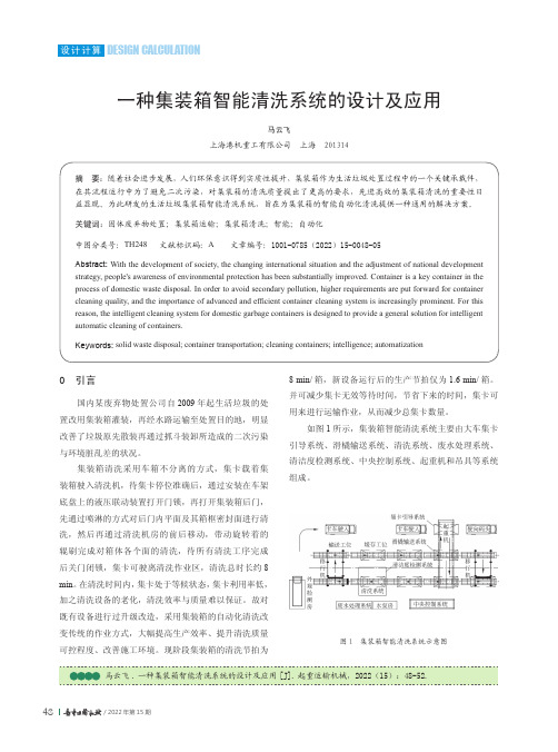
一种集装箱智能清洗系统的设计及应用马云飞上海港机重工有限公司 上海 201314摘 要:随着社会进步发展,人们环保意识得到实质性提升,集装箱作为生活垃圾处置过程中的一个关键承载件,在其流程运行中为了避免二次污染,对集装箱的清洗质量提出了更高的要求,先进高效的集装箱清洗的重要性日益显现。
为此研发的生活垃圾集装箱智能清洗系统,旨在为集装箱的智能自动化清洗提供一种通用的解决方案。
关键词:固体废弃物处置;集装箱运输;集装箱清洗;智能;自动化中图分类号:TH248 文献标识码:A 文章编号:1001-0785(2022)15-0048-05Abstract: With the development of society, the changing international situation and the adjustment of national developmentstrategy, people's awareness of environmental protection has been substantially improved. Container is a key container in the process of domestic waste disposal. In order to avoid secondary pollution, higher requirements are put forward for container cleaning quality, and the importance of advanced and efficient container cleaning system is increasingly prominent. For this reason, the intelligent cleaning system for domestic garbage containers is designed to provide a general solution for intelligent automatic cleaning of containers.Keywords: solid waste disposal; container transportation; cleaning containers; intelligence; automatization0 引言国内某废弃物处置公司自2009年起生活垃圾的处置改用集装箱灌装,再经水路运输至处置目的地,明显改善了垃圾原先散装再通过抓斗装卸所造成的二次污染与环境脏乱差的状况。
西得乐推出创新和可持续发展解决方案

西得乐推出创新和可持续发展解决方案
佚名
【期刊名称】《现代塑料》
【年(卷),期】2008(000)012
【摘要】作为全球领先的饮料、液体产品包装技术供应商,西得乐将在“2008年美国国际包装工业展(Pack Expo 2008)”上,展示其创新和可持续发展的解决方案。
【总页数】1页(P16)
【正文语种】中文
【中图分类】TS206
【相关文献】
1.西得乐面向饮料行业推出整线解决方案 [J],
2.西得乐推出SUPER COMBI智能解决方案 [J], 西得乐
3.西得乐在Pack Expo展会上推出创新和可持续发展解决方案,带来更高的生产力和成本节约 [J], 易美济
4.西得乐推出SUPER COMBI智能解决方案 [J],
5.西得乐在DRINKTEC上推出新一代饮料包装整线解决方案构 [J],
因版权原因,仅展示原文概要,查看原文内容请购买。
2017年12份最新APQC通用版流程分类框架PCF交流版
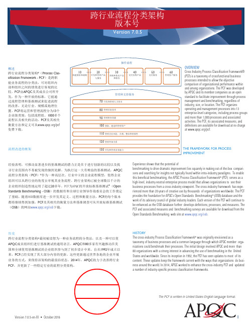
跨行业流程分类架构版本号Version 7.0.5概述跨行业流程分类架构®(Process Clas-sification Framework - PCF)是跨职能业务流程的分类法,可对组织内部和组织之间的绩效进行客观的比较。
PCF由APQC及其成员公司所开发,作为一种开放的标准,它能通过流程管理和基准测试来促进流程的改善,无论行业、规模或地理位置。
PCF将运营和管理流程分为13个企业级类别,包括流程组、1000多个流程以及相关的活动。
PCF及其相关衡量方法和定义可从/pcf免费下载。
流程改进的框架经验表明,可推动显著进步的基准测试的潜力正是在于进行创新的比较以及找寻行业范围内不易被发现的独到见解。
为执行这一大有裨益的基准测试,APQC 流程分类架构(PCF)®作为一种高层次、行业中立的企业流程模型,使得企业组织可以从跨行业的角度去审视其业务流程。
跨行业架构已被全球数以千计的企业组织创造性地运用了超过20多年。
PCF为APQC的开放标准基准测试®(Open Standards Benchmarking - OSB)的数据库和全球行业领导咨询委员会的工作奠定了基础。
随着OSB数据库进一步开发其定义、过程和衡量方法,PCF的每个版本都将继续得到加强。
PCF及其相关的衡量方法和基准调查可从开放标准基准测试(OSB)的网站/osb下载。
历史跨行业流程分类架构®最初被设想为一种业务流程的分类法,以及一种可以使APQC成员组织们进行基准测试的通用语言。
APQC和80多家有兴趣推动在美国和全球使用基准测试的企业组织参与到了初步设计中来。
自从1992年成立以来,PCF已经实现了其大部分内容的更新。
这些更新通过世界各地的企业开展业务的方式,来保持该架构的最前沿状态。
2014年,APQC致力于改善跨行业PCF,并更新了一些特定行业的流程分类架构。
OVERVIEWCross Industry Process Classification Framework®(PCF) is a taxonomy of crossfunctional businessprocesses intended to allow the objectivecomparison of organizational performance withinand among organizations. The PCF was developedby APQC and its member companies as an openstandard to facilitate improvement through processmanagement and benchmarking, regardless ofindustry, size, or location. The PCF organizesoperating and management processes into 13enterprise-level categories, including process groupsand more than 1,000 processes and associatedactivities. The PCF, its associated measures, anddefinitions are available for download at no chargeat /pcf.THE FRAMEWORK FOR PROCESSIMPROVEMENTExperience shows that the potential ofbenchmarking to drive dramatic improvement lies squarely in making out-of-the-box compari-sons and searching for insights not typically found within intra-industry paradigms. To enable this beneficial benchmarking, the APQC Process Classification Framework® (PCF) serves as a high-level, industry-neutral enterprise process model that allows organizations to see their business processes from a cross-industry viewpoint. The cross-industry framework has expe-rienced more than 20 years of creative use by thousands of organizations worldwide. The PCF provides the foundation for APQC’s Open Standards Benchmarking® (OSB) database and the work of its advisory council of global industry leaders. Each version of the PCF will continue to be enhanced as the OSB database further develops definitions, processes, and measures. The PCF and associated measures and benchmarking surveys are available for download from the Open Standards Benchmarking web site at /osb.HISTORYThe cross-industry Process Classification Framework® was originally envisioned as a taxonomy of business processes and a common language through which APQC member orga-nizations could benchmark their processes. The initial design involved APQC and more than80 organizations with a strong interest in advancing the use of benchmarking in the United States and worldwide. Since its inception in 1992, the PCF has seen updates to most of its content. These updates keep the framework current with the ways that organizations do busi-ness around the world. In 2014, APQC worked to enhance the cross-industry PCF and updated a number of industry-specific process classification frameworks.The PCF is written in United States English language format.管理和支持服务7.0开发和管理人力资本8.0管理信息技术9.0管理财务资源10.0获取、建造和管理资产11.0管理企业风险、合规、整治和持续性12.0管理外部关系13.0开发和管理业务能力2017.11.25汽车行业流程分类框架PCQ群459842191Version 7.0.5-en-XI • October 2016 12Permission granted to photocopy for personal use. ©2016 APQC. ALL RIGHTS RESERVED.期待跨行业和行业流程分类架构正不断发展其模型, APQC 会继续将这些模型予以加强和改进。
进修工作总结
进修工作总结英文回答:Continuing Education Summary Report。
Over the past year, I have eagerly pursued continuing education opportunities to enhance my skills and knowledge. By actively engaging in professional development workshops, conferences, and online courses, I have acquired valuable insights that have significantly contributed to my professional growth.One notable experience was my participation in a workshop on project management best practices. This immersive three-day program provided comprehensive training on the latest methodologies, tools, and techniques for effective project execution. Through interactive exercises and case studies, I gained practical knowledge that I have directly applied to my daily work, resulting in improved project outcomes and increased efficiency.Another highlight of my continuing education journey was attending an industry conference focused on data analytics. As the field of data analysis continues to evolve rapidly, it is crucial for me to stay up-to-date with emerging trends and innovations. The conference featured presentations from leading experts, providing me with invaluable perspectives on the latest advancements in data analysis techniques, machine learning, and artificial intelligence.Additionally, I have dedicated time to completing several online courses through reputable platforms. These self-paced courses have allowed me to explore specialized topics such as Agile development, cloud computing, and cybersecurity. The flexibility of online learning has enabled me to tailor my training to my specific interests and career goals.Impact on Professional Development。
- 1、下载文档前请自行甄别文档内容的完整性,平台不提供额外的编辑、内容补充、找答案等附加服务。
- 2、"仅部分预览"的文档,不可在线预览部分如存在完整性等问题,可反馈申请退款(可完整预览的文档不适用该条件!)。
- 3、如文档侵犯您的权益,请联系客服反馈,我们会尽快为您处理(人工客服工作时间:9:00-18:30)。
Design behavioral model
Design behavioral model
Implement FPGA Implement code FPGA code
••Re-use Re-use • LabVIEW built-in ••LabVIEW built-in Xilinx CORE Generator •Xilinx CORE • IPNet/NI Labs Generator • Create •IPNet/NI Labs • LabVIEW • Convert •Create to FXP • Schedule code •LabVIEW • Outside SCTL • Inside SCTL •Convert to FXP • VHDL/Verilog
Design behavioral model
• Establish functional requirements • Establish performance requirements • Throughput / Speed • Precision • Incorporate target knowledge • Use high level LabVIEW functions and toolkits
Cannot realize behavioral model
14
Existing LabVIEW FPGA IP
• See what LabVIEW FPGA IP is already available • Sources
LabVIEW FPGA palette Xilinx Coregen IP /ipnet/ https:///content/groups/ni-labs
ADC 14-bit 100 MS/s
100 MS/s Digitizer
Average 1000 Points
NI PXIe-8133 PXI Express Controller
1.73 GHz Quad Core
Host Computer Display
7
Design Problem
Analog Signal
Implement FPGA code
• Re-use • LabVIEW built-in • Xilinx CORE Generator • IPNet/NI Labs • Create • LabVIEW • Convert to FXP • Schedule code • Outside SCTL • Inside SCTL • VHDL/Verilog
•Establish functional • Establish functional requirements requirements •Establish • Establish performance performance requirements requirements • Throughput / •Throughput / Speed Speed • Precision •Precision • Incorporate target •Incorporate target knowledge • Use high level knowledge LabVIEW functions •Use high level and toolkits LabVIEW functions and toolkits
Simulation
• On the host computer • Simulated or previously-obtained data • Catches implementation errors before compilation
Compile
• Compile the FPGA
Test
• Simulated data at speed • Real-world I/O
Simulation does not function correctly or meet performance requirements
Cannot realize behavioral model
10
Establish Requirements
Digital design with FPGAs DSP processing in FPGAs
• I am a long term LabVIEW FPGA user • I am a huge LabVIEW FPGA fan • I am currently designing RF DSP with LabVIEW FPGA
• Simulated data at speed • Real-world I/O
Simulation does not function correctly or meet performance requirements
Cannot realize behavioral model
9
LabVIEW FPGA Design Flow
• Do a few test compiles
12
Host Computer Behavior Model
• High level LabVIEW implementation of your design problem
Functionally accurate Doesn’t need to meet timing requirements High level functions Floating Point Arrays For/while loops
• Simulated data at speed • Real-world I/O
•Schedule code •Outside SCTL •Inside SCTL Simulation •VHDL/Verilog does not function correctly or meet performance requirements
• Establish functional requirements • Establish performance requirements • Throughput / Speed • Precision • Incorporate target knowledge • Use high level LabVIEW functions and toolkits
Implement FPGA code
• Re-use • LabVIEW built-in • Xilinx CORE Generator • IPNet/NI Labs • Create • bVIEW • Convert to FXP • Schedule code • Outside SCTL • Inside SCTL • VHDL/Verilog
Host Computer Display
NI PXIe-8133 PXI Express Controller
1.73 GHz Quad Core
8
LabVIEW FPGA Design Flow
Design does not meet performance requirements in real-world operating conditions Does not meet timing or size requirements
13
LabVIEW FPGA Design Flow
Design does not meet performance requirements in real-world operating conditions Does not meet timing or size requirements
Design behavioral model
11
Know Your Hardware Target
• I/O
Sample Rates – 100 MS/s Resolution – 14-bits
• FPGA
Size – 58,880 FF and LUTs, 488 BRAM, 640 DSP48Es Hardware components – BRAM, DSP48E Speed – 100 MHz is no problem for most code
• Compare IP to your design constraints
15
Host code with Functions Available in LabVIEW FPGA
• Rewrite the code using
Functions available in LV FPGA
• Host computer version
• Functional Requirements
Digitize analog signal Average every 1000 samples Display averaged data on the host computer
• Performance Requirements
100 MS/s ADC sample rate 14-bit ADC resolution 16-bit averager output resolution
3
Who are you?
• Do you know what FPGAs are? • Have you programmed with LabVIEW FPGA? • Hopefully you are eager to learn more about the most efficient way to implement your application with LabVIEW FPGA
