从无线电世界到单片机世界 毕业论文外文翻译
单片机 外文翻译 外文文献 英文文献 单片机简介 中英对
单片机外文翻译外文文献英文文献单片机简介中英对原文来源图书馆电子资源Single chip brief introductionThe monolithic integrated circuit said that the monolithic micro controller, it is not completes some logical function the chip, but integrates a computer system to a chip on. Summary speaking: A chip has become a computer. Its volume is small, the quality is light, and the price cheap, for the study, the application and the development has provided the convenient condition. At the same time, the study use monolithic integrated circuit is understands the computer principle and the structure best choice.The monolithic integrated circuit interior also uses with the computer function similar module, for instance CPU, memory, parallel main line, but also has with the hard disk behave identically the memory component7 what is different is its these part performance is opposite our home-use computer weak many, but the price is also low, generally does not surpass 10 Yuan then Made some control electric appliance one kind with it is not the 'very complex work foot, We use now the completely automatic drum washer, the platoon petti-coat pipe: VCD and so on Inside the electrical appliances may see its form! It is mainly takes the control section the core part.It is one kind of online -like real-time control computer, online -like is the scene control, needs to have the strong antijamming ability,the low cost, this is also and the off-line type computer (for instance home use PC,) main differenceThe monolithic integrated circuit is depending on the procedure, and may revise. Realizes the different function through the different procedure, particularly special unique some functions, this is other component needs to take the very big effort to be able to achieve, some are the flowered big strength is also very difficult to achieve. One is not the very complex function, if develops in the 50s with the US 74 series, or the 60s's CD4000 series these pure hardware do decides, the electric circuit certainly arc a big PCB board ! But if, if succeeded in the 70s with the US puts in the market the series monolithic integrated circuit, the result will have the huge difference. Because only the monolithic integrated circuit compiles through you the procedure may realize the high intelligence, high efficiency, as well as redundant reliabilityThe CPU is the key component of a digital computer. Its purpose isto decode instruction received from memory and perform transfers, arithmetic, logic, and control operations with data stored in internal registers, memory, or I/O interface units. Externally, the CPU provides one or more buses for transferring instructions, data, and control information to and from components connected to it. A microcontroller is present in the keyboard and in the monitor in the generic computer; thus these components are also shaded. In such microcontrollers, the CPU may be quite different from those discussed in this chapter. The wordlengths may be short, the number of registers small, and the instruction sets limited. Performance, relatively speaking, is poor, but adequatefor the task. Most important, the cost of these microcontrollers is very low, making their use cost effective.Because the monolithic integrated circuit to the cost is sensitive, therefore present occupies the dominant status the software is the most preliminary assembly language7 it was except the binary machine code above the most preliminary language, sincewhy were such preliminary must use?Why high-level did the language already achieve the visualization programming level not to use? The reason is very simple, is the monolithic integrated circuit docs not have home computer such CPU, and also has not looked like the hard disk such mass memory equipment. Inside even if a visualization higher order language compilation script only then a button, also will achieve several dozens K the sizes! Does not speak anything regarding the home use PC hard disk, but says regarding the monolithic integrated circuit cannot accept. The monolithic integrated circuit in the hardware source aspect's use factor must very Gao Caixing, therefore assembly, although primitive actually massively is using, Same truth, if attains supercomputer's on operating system and the application software home use PC to come up the movement, home use PC could also not withstand.It can be said that the 20th century surmounted three "the electricity" the time, namely the electrical time, the Electronic Ageand already entered computer time. However, this kind of computer, usually refers to the personal computer, is called PC machine. It by the main engine, the keyboard, the monitor and so on is composed. Also has a kind of computer, most people actually not how familiar. This kind of computer is entrusts with the intelligence each kind of mechanical monolithic integrated circuit (also to call micro controller). , This kind of computer's smallest system only has used as the name suggests a piece of integrated circuit, then carries on the simple operation and the control. Because its volume is small, usually hides in is accused the machinery "the belly". It in the entire installment, plays is having like the human brains role, it went wrong, the entire installment paralyzed. Now, this kind of monolithic integrated circuit's use domain already very widespread, like the intelligent measuring appliance, the solid work paid by time control, the communication equipment, the guidance system, the domestic electric appliances and so on, Once each product used the monolithic integrated circuit, could get up causes the effect which the product turned to a new generation, often before product range crown by adjective---- …intelligence?, like intelligence washer and so on. Now some factory's technical personnel or other extra-curricular electronic exploiter do certain products, are not theelectric circuit are too complex, is the function is too simple, and is imitated extremely easily. Investigates its reason, possibly on card, in the product has not used on the monolithic integrated circuit or other programmable logical component.单片机简介单片机又称单片微控制器,它不是完成某一个逻辑功能的芯片,而是把一个计算机系统集成到一个芯片上。
从无线电世界到单片机世界
英文From radio world to monolithic integrated circuit world The modern computer technology industrial revolution, leads the world economics from the capital economy to the knowledge economy time. In the electronic world domain, also enters from the 20th century radio times to the 21st century take computer technology as the central intellectualized modern electron system time. The modern electron system basic core is inserts the type computer system (abbreviation to insert type system), but the monolithic integrated circuit is most typical, is most broad popularly, inserts the type system.First, the radio world has accomplished several generation of people with outstanding ability In the 20th century 560 ages, most has the advanced electronic technology which represents is the radio technology, including radio broadcasting, reception, wireless communication (telegram), telemetering, remote control, remote letter technology and so on amateur station, radiolocation, navigation. The early time was these electronic technologies leads many young people to march into the marvelous electronic world, the radio technology has demonstrated at that time the technical life wonderful foreground. The electronic science started to form an emerging discipline. The radioelectronics, the wireless communication started the electronic world course.The radio technology not only has become at that time advanced science and technology representative, moreover from popularizes to the specialized scientific domain, has attracted the general young people, and caused them to find the infinite pleasure. From head of a bed crystal set to super-heterodyne; From wireless electrically initiated registration amateur station; From telephone, electric bell to radio operation model. The radio technology became the young people popular science, the technical education is most popular at that time, the most broad content. Until now, many older generations' engineers, the expert, professor in the past all were the radio amateur. The radio technical infinite pleasure, the radio technical comprehensive training, from the electronics basic principle, the electronic primary device foundation to the radio telecontrol, the telemetering, the remote letter electron system manufacture, trained several generation of technical people with outstanding ability. Second, from radio time to electronic technology popular time。
单片机英文文献及翻译)
Validation and Testing of Design Hardening for Single Event Effects Using the 8051 MicrocontrollerAbstractWith the dearth of dedicated radiation hardened foundries, new and novel techniques are being developed for hardening designs using non-dedicated foundry services. In this paper, we will discuss the implications of validating these methods for the single event effects (SEE) in the space environment. Topics include the types of tests that are required and the design coverage (i.e., design libraries: do they need validating for each application?). Finally, an 8051 microcontroller core from NASA Institute of Advanced Microelectronics (IAμE) CMOS Ultra Low Power Radiation Tolerant (CULPRiT) design is evaluated for SEE mitigative techniques against two commercial 8051 devices.Index TermsSingle Event Effects, Hardened-By-Design, microcontroller, radiation effects.I. INTRODUCTIONNASA constantly strives to provide the best capture of science while operating in a space radiation environment using a minimum of resources [1,2]. With a relatively limited selection of radiation-hardened microelectronic devices that are often two or more generations of performance behind commercialstate-ofthe-art technologies, NASA’s performance of this task is quite challenging. One method of alleviating this is by the use of commercial foundry alternatives with no or minimally invasive design techniques for hardening. This is often called hardened-by-design (HBD).Building custom-type HBD devices using design libraries and automated design tools may provide NASA the solution it needs to meet stringent science performance specifications in a timely,cost-effective, and reliable manner.However, one question still exists: traditional radiation-hardened devices have lot and/or wafer radiation qualification tests performed; what types of tests are required for HBD validation?II. TESTING HBD DEVICES CONSIDERATIONSTest methodologies in the United States exist to qualify individual devices through standards and organizations such as ASTM, JEDEC, and MIL-STD- 883. Typically, TID (Co-60) and SEE (heavy ion and/or proton) are required for device validation. So what is unique to HBD devices?As opposed to a “regular” commercial-off-the-shelf (COTS) device or application specific integrated circuit (ASIC) where no hardening has been performed, one needs to determine how validated is the design library as opposed to determining the device hardness. That is, by using test chips, can we “qualify” a future device using the same library?Consider if Vendor A has designed a new HBD library portable to foundries B and C. A test chip is designed, tested, and deemed acceptable. Nine months later a NASA flight project enters the mix by designing a new device using Vendor A’s library. Does this device require complete radiation qualification testing? To answer this, other questions must be asked.How complete was the test chip? Was there sufficient statistical coverage of all library elements to validate each cell? If the new NASA design uses a partially or insufficiently characterized portion of the design library, full testing might be required. Of course, if part of the HBD was relying on inherent radiation hardness of a process, some of the tests (like SEL in the earlier example) may be waived.Other considerations include speed of operation and operating voltage. For example, if the test chip was tested statically for SEE at a power supply voltage of 3.3V, is the data applicable to a 100 MHz operating frequency at 2.5V? Dynamic considerations (i.e., nonstatic operation) include the propagated effects of Single Event Transients (SETs). These can be a greater concern at higher frequencies.The point of the considerations is that the design library must be known, the coverage used during testing is known, the test application must be thoroughly understood and the characteristics of the foundry must be known. If all these are applicable or have been validated by the test chip, then no testing may be necessary. A task within NASA’s Electronic Parts and Packaging (NEPP) Program was performed to explore these types of considerations.III. HBD TECHNOLOGY EVALUATION USING THE 8051 MICROCONTROLLERWith their increasing capabilities and lower power consumption, microcontrollers are increasingly being used in NASA and DOD system designs. There are existing NASA and DoD programs that are doing technology development to provide HBD. Microcontrollers are one such vehicle that is being investigated to quantify the radiation hardness improvement. Examples of these programs are the 8051 microcontroller being developed by Mission Research Corporation (MRC) and the IAμE (the focus of this study). As these HBD technologies become available, validation of the technology, in the natural space radiation environment, for NASA’s use in spaceflight systems is required.The 8051 microcontroller is an industry standard architecture that has broad acceptance, wide-ranging applications and development tools available. There are numerous commercial vendors that supply this controller or have it integrated into some type of system-on-a-chip structure. Both MRC and IAμE chose this device to demonstrate two distinctly different technologies for hardening. The MRC example of this is to use temporal latches that require specific timing to ensure that single event effects are minimized. The IAμE technology uses ultra low power, and layout and architecture HBD design rules to achieve their results. These are fundamentally different than the approach by Aeroflex-United Technologies Microelectronics Center (UTMC), the commercial vendor of a radiation–hardened 8051, that built their 8051 microcontroller using radiationhardened processes. This broad range of technology within one device structure makes the 8051an ideal vehicle for performing this technology evaluation.The objective of this work is the technology evaluation of the CULPRiT process [3] from IAμE. The process has been baselined against two other processes, the standard 8051 commercial device from Intel and a version using state-of-the-art processing from Dallas Semiconductor. By performing this side-by-side comparison, the cost benefit, performance, and reliability trade study can be done.In the performance of the technology evaluation, this task developed hardware and software for testing microcontrollers. A thorough process was done to optimize the test process to obtain as complete an evaluation as possible. This included taking advantage of the available hardware and writing software that exercised the microcontroller such that all substructures of the processor were evaluated. This process is also leading to a more complete understanding of how to test complex structures, such as microcontrollers, and how to more efficiently test these structures in the future.IV. TEST DEVICESThree devices were used in this test evaluation. The first is the NASA CULPRiT device, which is the primary device to be evaluated. The other two devices are two versions of a commercial 8051, manufactured by Intel and Dallas Semiconductor, respectively.The Intel devices are the ROMless, CMOS version of the classic 8052 MCS-51 microcontroller. They are rated for operation at +5V, over a temperature range of 0 to 70 °C and at a clock speeds of 3.5 MHz to 24 MHz. They are manufactured in Intel’s P629.0 CHMOS III-E process.The Dallas Semiconductor devices are similar in that they are ROMless 8052 microcontrollers, but they are enhanced in various ways. They are rated for operation from 4.25 to 5.5 Volts over 0 to 70 °C at clock speeds up to 25 MHz. They have a second full serial port built in, seven additional interrupts, a watchdog timer, a power fail reset, dual data pointers and variable speed peripheral access. In addition, the core is redesigned so that the machine cycle is shortened for most instructions, resulting in an effective processing ability that is roughly 2.5 times greater (faster) than the standard 8052 device. None of these features, other than those inherent in the device operation, were utilized in order to maximize the similarity between the Dallas and Intel test codes.The CULPRiT technology device is a version of the MSC-51 family compatible C8051 HDL core licensed from the Ultra Low Power (ULP) process foundry. The CULPRiT technology C8051 device is designed to operate at a supply voltage of 500 mV and includes an on-chip input/output signal level-shifting interface with conventional higher voltage parts. The CULPRiT C8051 device requires two separate supply voltages; the 500 mV and the desired interface voltage. The CULPRiT C8051 is ROMless and is intended to be instruction set compatible with the MSC-51 family.V. TEST HARDWAREThe 8051 Device Under Test (DUT) was tested as a component of a functional computer. Aside from DUT itself, the other componentsof the DUT computer were removed from the immediate area of the irradiation beam.A small card (one per DUT package type) with a unique hard-wired identifier byte contained the DUT, its crystal, and bypass capacitors (and voltage level shifters for the CULPRiT DUTs). This "DUT Board" was connected to the "Main Board" by a short 60-conductor ribbon cable. The Main Board had all other components required to complete the DUT Computer, including some which nominally are not necessary in some designs (such as external RAM, external ROM and address latch). The DUT Computer and the Test Control Computer were connected via a serial cable and communications were established between the two by the Controller (that runs custom designed serial interface software). This Controller software allowed for commanding of the DUT, downloading DUT Code to the DUT, and real-time error collection from the DUT during and post irradiation. A 1 Hz signal source provided an external watchdog timing signal to the DUT, whose watchdog output was monitored via an oscilloscope. The power supply was monitored to provide indication of latchup.VI. TEST SOFTWAREThe 8051 test software concept is straightforward. It was designed to be a modular series of small test programs each exercising a specific part of the DUT. Since each test was stand alone, they were loaded independently of each other for execution on the DUT. This ensured that only the desired portion of the 8051 DUT was exercised during the test and helped pinpoint location of errors that occur during testing. All test programs resided on the controller PC until loaded via the serial interface to the DUT computer. In this way, individual tests could have been modified at any time without the necessity of burning PROMs. Additional tests could have also been developed and added without impacting the overall test design. The only permanent code, which was resident on the DUT, was the boot code and serial code loader routines that established communications between the controller PC and the DUT.All test programs implemented:• An external Universal Asynchronous Receive and Transmit device (UART) for transmission of error information and communication to controller computer.• An external real-time clock for data error tag.•A watchdog routine designed to provide visual verification of 8051 health and restart test code if necessary.• A "foul-up" routine to reset program counter if it wanders out of code space.• An external telemetry data storage memory to provide backup of data in the event of an interruption in data transmission.The brief description of each of the software tests used is given below. It should be noted that for each test, the returned telemetry (including time tag) was sent to both the test controller and the telemetry memory, giving the highest reliability that all data is captured.Interrupt –This test used 4 of 6 available interrupt vectors (Serial, External, Timer0 Overflow, and Timer1 Overflow) to trigger routines that sequentially modified a value in the accumulator which was periodically compared to a known value. Unexpected values were transmitted with register information.Logic –This test performed a series of logic and math computations and provided three types of error identifications: 1) addition/subtraction, 2) logic and 3) multiplication/division. All miscompares of computations and expected results were transmitted with other relevant register information.Memory – This test loaded internal data memory at locations D:0x20 through D:0xff (or D:0x20 through D:0x080 for the CULPRiT DUT), indirectly, with an 0x55 pattern. Compares were performed continuously and miscompares were corrected while error information and register values were transmitted.Program Counter -The program counter was used to continuously fetch constants at various offsets in the code. Constants were compared with known values and miscompares were transmitted along with relevant register information. Registers – This test loaded each of four (0,1,2,3) banks of general-purpose registers with either 0xAA (for banks 0 and 2) or 0x55 (for banks 1 and 3). The pattern was alternated in order to test the Program Status Word (PSW) special function register, which controls general-purpose register bank selection. General-purpose register banks were then compared with their expected values. All miscompares were corrected and error information was transmitted.Special Function Registers (SFR) – This test used learned static values of 12 out 21 available SFRs and then constantly compared the learned value with the current one. Miscompares were reloaded with learned value and error information was transmitted.Stack – This test performed arithmetic by pushing and popping operands on the stack. Unexpected results were attributed to errors on the stack or to the stack pointer itself and were transmitted with relevant register information.VII. TEST METHODOLOGYThe DUT Computer booted by executing the instruction code located at address 0x0000. Initially, the device at this location was an EPROM previously loaded with "Boot/Serial Loader" code. This code initialized the DUT Computer and interface through a serial connection to the controlling computer, the "Test Controller". The DUT Computer downloaded Test Code and put it into Program Code RAM (located on the Main Board of the DUT Computer). It then activated a circuit which simultaneously performed two functions: held the DUT reset line active for some time (~10 ms); and, remapped the Test Code residing in the Program Code RAM to locate it to address 0x0000 (the EPROM will no longer be accessible in the DUT Computer's memory space). Upon awaking from the reset, the DUT computer again booted by executing the instruction code at address 0x0000, except this time that code was not be the Boot/Serial Loader code but the Test Code.The Test Control Computer always retained the ability to force the reset/remap function, regardless of the DUT Computer's functionality. Thus, if the test ran without a Single Event Functional Interrupt (SEFI) either the DUT Computer itselfor the Test Controller could have terminated the test and allowed the post-test functions to be executed. If a SEFI occurred, the Test Controller forced a reboot into Boot/Serial Loader code and then executed the post-test functions. During any test of the DUT, the DUT exercised a portion of its functionality (e.g., Register operations or Internal RAM check, or Timer operations) at the highest utilization possible, while making a minimal periodic report to the Test Control Computer to convey that the DUT Computer was still functional. If this reportceased, the Test Controller knew that a SEFI had occurred. This periodic data was called "telemetry". If the DUT encountered an error that was not interrupting the functionality (e.g., a data register miscompare) it sent a more lengthy report through the serial port describing that error, and continued with the test.VIII.DISCUSSIONA. Single Event LatchupThe main argument for why latchup is not an issue for the CULPRiT devices is that the operating voltage of 0.5 volts should be below the holding voltage required for latchup to occur. In addition to this, the cell library used also incorporates the heavy dual guard-barring scheme [4]. This scheme has been demonstrated multiple times to be very effective in rendering CMOS circuits completely immune to SEL up to test limits of 120 MeV-cm2/mg. This is true in circuits operating at 5, 3.3, and 2.5 Volts, as well as the 0.5 Volt CULPRiT circuits. In one case, a 5 Volt circuit fabricated on noncircuits wafers even exhibited such SEL immunity.B. Single Event UpsetThe primary structure of the storage unit used in the CULPRiT devices is the Single Event Resistant Topology (SERT) [5]. Given the SERT cell topology and a single upset node assumption, it is expected that the SERT cell will be completely immune to SEUs occurring internal to the memory cell itself. Obviously there are other things going on. The CULPRiT 8051 results reported here are quite similar to some resultsobtained with a CULPRiT CCSDS lossless compression chip (USES) [6]. The CULPRiT USES was synthesized using exactly the same tools and library as the CULPRiT 8051.With the CULPRiT USES, the SEU cross section data [7] was taken as a function of frequency at two LET values, 37.6 and 58.5 MeV-cm2/mg. In both cases the data fit well to a linear model where cross section is proportional to clock. In the LET 37.6 case, the zero frequency intercept occurred essentially at the zero cross section point, indicating that virtually all of these SEUs are captured SETs from the combinational logic. The LET 58.5 data indicated that the SET (frequency dependent) component is sitting on top of a "dc-bias" component –presumably a second upset mechanism is occurring internal to the SERT cells only at a second, higher LET threshold.The SET mitigation scheme used in the CULPRiT devices is based on the SERT cell's fault tolerant input property when redundant input data is provided to separate storage nodes. The idea is that the redundant input data is provided through a total duplication of combinational logic (referred to as “dual rail design”) such that a simple SET on one rail cannot produce an upset. Therefore, some other upset mechanism must be happening. It is possible that a single particle strike is placing an SET on both halves of the logic streams, allowing an SET to produce an upset. Care was taken to separate the dual sensitive nodes in the SERT cell layouts but the automated place-and-route of the combinatorial logic paths may have placed dual sensitive nodes close enough.At this point, the theory for the CULPRiT SEU response is that at about an LET of 20, the energy deposition is sufficiently wide enough (and in the right locations) to produce an SET in both halves of the combinatorial logic streams. Increasing LET allows for more regions to be sensitive to this effect, yielding a larger cross section. Further, the second SEU mechanism that starts at an LET of about 40-60 has to do with when the charge collection disturbance cloud gets large enough to effectively upset multiples of the redundant storage nodes within the SERT cell itself. In this 0.35 μm library, the node separation is several microns. However, since it takes less charge to upset a node operating at 0.5 Volts, with transistors having effective thresholds around 70 mV, this is likely the effect being observed. Also the fact that the per-bit memory upset cross section for the CULPRiT devices and the commercial technologies are approximately equal, as shown in Figure 9, indicates that the cell itself has become sensitive to upset.IX. SUMMARYA detailed comparison of the SEE sensitivity of a HBD technology (CULPRiT) utilizing the 8051 microcontroller as a test vehicle has been completed. This paper discusses the test methodology used and presents a comparison of the commercial versus CULPRiT technologies based on the data taken. The CULPRiT devices consistently show significantly higher threshold LETs and an immunity to latchup. In all but the memory test at the highest LETs, the cross section curves for all upset events is one to two orders of magnitude lower than the commercial devices. Additionally, theory is presented, based on the CULPRiT technology, that explain these results.This paper also demonstrates the test methodology for quantifying the level of hardness designed into a HBD technology. By using the HBD technology in a real-world device structure (i.e., not just a test chip), and comparing results to equivalent commercial devices, one can have confidence in the level of hardness that would be available from that HBD technology in any circuit application.ACKNOWLEDGEMENTSThe authors of this paper would like to acknowledge the sponsors of this work. These are the NASA Electronic Parts and Packaging Program (NEPP), NASA Flight Programs, and the Defense Threat Reduction Agency (DTRA).。
毕业设计(论文)外文原文及译文
毕业设计(论文)外文原文及译文一、外文原文MCUA microcontroller (or MCU) is a computer-on-a-chip. It is a type of microcontroller emphasizing self-sufficiency and cost-effectiveness, in contrast to a general-purpose microprocessor (the kind used in a PC).With the development of technology and control systems in a wide range of applications, as well as equipment to small and intelligent development, as one of the single-chip high-tech for its small size, powerful, low cost, and other advantages of the use of flexible, show a strong vitality. It is generally better compared to the integrated circuit of anti-interference ability, the environmental temperature and humidity have better adaptability, can be stable under the conditions in the industrial. And single-chip widely used in a variety of instruments and meters, so that intelligent instrumentation and improves their measurement speed and measurement accuracy, to strengthen control functions. In short,with the advent of the information age, traditional single- chip inherent structural weaknesses, so that it show a lot of drawbacks. The speed, scale, performance indicators, such as users increasingly difficult to meet the needs of the development of single-chip chipset, upgrades are faced with new challenges.The Description of AT89S52The AT89S52 is a low-power, high-performance CMOS 8-bit microcontroller with 8K bytes of In-System Programmable Flash memory. The device is manufactured using Atmel's high-density nonvolatile memory technology and is compatible with the industry-standard 80C51 instruction set and pinout. The on-chip Flash allows the program memory to be reprogrammed in-system or by a conventional nonvolatile memory programmer. By combining a versatile 8-bit CPU with In-System Programmable Flash on a monolithic chip, the Atmel AT89S52 is a powerful microcontroller which provides a highly-flexible and cost-effective solution to many embedded control applications.The AT89S52 provides the following standard features: 8K bytes ofFlash, 256 bytes of RAM, 32 I/O lines, Watchdog timer, two data pointers, three 16-bit timer/counters, a six-vector two-level interrupt architecture, a full duplex serial port, on-chip oscillator, and clock circuitry. In addition, the AT89S52 is designed with static logic for operation down to zero frequency and supports two software selectable power saving modes. The Idle Mode stops the CPU while allowing the RAM, timer/counters, serial port, and interrupt system to continue functioning. The Power-down mode saves the RAM contents but freezes the oscillator, disabling all other chip functions until the next interrupt or hardware reset.Features• Compatible with MCS-51® Products• 8K Bytes of In-System Programmable (ISP) Flash Memory– Endurance: 1000 Write/Erase Cycles• 4.0V to 5.5V Operating Range• Fully Static Operation: 0 Hz to 33 MHz• Three-level Program Memory Lock• 256 x 8-bit Internal RAM• 32 Programmable I/O Lines• Three 16-bit Timer/Counters• Eight Interrupt Sources• Full Duplex UART Serial Channel• Low-power Idle and Power-down Modes• Interrupt Recovery from Power-down Mode• Watchdog Timer• Dual Data Pointer• Power-off FlagPin DescriptionVCCSupply voltage.GNDGround.Port 0Port 0 is an 8-bit open drain bidirectional I/O port. As an output port, each pin can sink eight TTL inputs. When 1s are written to port 0 pins, the pins can be used as high-impedance inputs.Port 0 can also be configured to be the multiplexed low-order address/data bus during accesses to external program and data memory. In this mode, P0 has internal pullups.Port 0 also receives the code bytes during Flash programming and outputs the code bytes during program verification. External pullups are required during program verification.Port 1Port 1 is an 8-bit bidirectional I/O port with internal pullups. The Port 1 output buffers can sink/source four TTL inputs. When 1s are written to Port 1 pins, they are pulled high by the internal pullups and can be used as inputs. As inputs, Port 1 pins that are externally being pulled low will source current (IIL) because of the internal pullups.In addition, P1.0 and P1.1 can be configured to be the timer/counter 2 external count input (P1.0/T2) and the timer/counter 2 trigger input (P1.1/T2EX), respectively.Port 1 also receives the low-order address bytes during Flash programming and verification.Port 2Port 2 is an 8-bit bidirectional I/O port with internal pullups. The Port 2 output buffers can sink/source four TTL inputs. When 1s are written to Port 2 pins, they are pulled high by the internal pullups and can be used as inputs. As inputs, Port 2 pins that are externally being pulled low will source current (IIL) because of the internal pullups.Port 2 emits the high-order address byte during fetches from external program memory and during accesses to external data memory that use 16-bit addresses (MOVX @ DPTR). In this application, Port 2 uses strong internal pull-ups when emitting 1s. During accesses to external data memory that use 8-bit addresses (MOVX @ RI), Port 2 emits the contents of the P2 Special Function Register.Port 2 also receives the high-order address bits and some control signals during Flash programming and verification.Port 3Port 3 is an 8-bit bidirectional I/O port with internal pullups. The Port 3 output buffers can sink/source four TTL inputs. When 1s are written to Port 3 pins, they are pulled high by the internal pullups and can be used as inputs. As inputs, Port 3 pins that are externally being pulled low will source current (IIL) because of the pullups.Port 3 also serves the functions of various special features of the AT89S52, as shown in the following table.Port 3 also receives some control signals for Flash programming and verification.RSTReset input. A high on this pin for two machine cycles while the oscillator is running resets the device. This pin drives High for 96 oscillator periods after the Watchdog times out. The DISRTO bit in SFR AUXR (address 8EH) can be used to disable this feature. In the default state of bit DISRTO, the RESET HIGH out feature is enabled.ALE/PROGAddress Latch Enable (ALE) is an output pulse for latching the low byte of the address during accesses to external memory. This pin is also the program pulse input (PROG) during Flash programming.In normal operation, ALE is emitted at a constant rate of 1/6 the oscillator frequency and may be used for external timing or clocking purposes. Note, however, that one ALE pulse is skipped during each access to external data memory.If desired, ALE operation can be disabled by setting bit 0 of SFR location 8EH. With the bit set, ALE is active only during a MOVX or MOVC instruction. Otherwise, the pin is weakly pulled high. Setting the ALE-disable bit has no effect if the microcontroller is in external execution mode.PSENProgram Store Enable (PSEN) is the read strobe to external program memory. When the AT89S52 is executing code from external program memory, PSENis activated twice each machine cycle, except that two PSEN activations are skipped during each access to external data memory.EA/VPPExternal Access Enable. EA must be strapped to GND in order to enable the device to fetch code from external program memory locations starting at 0000H up to FFFFH. Note, however, that if lock bit 1 is programmed, EA will be internally latched on reset. EA should be strapped to VCC for internal program executions.This pin also receives the 12-volt programming enable voltage (VPP) during Flash programming.XTAL1Input to the inverting oscillator amplifier and input to the internal clock operating circuit.XTAL2Output from the inverting oscillator amplifier.Special Function RegistersNote that not all of the addresses are occupied, and unoccupied addresses may not be implemented on the chip. Read accesses to these addresses will in general return random data, and write accesses will have an indeterminate effect.User software should not write 1s to these unlisted locations, since they may be used in future products to invoke new features. In that case, the reset or inactive values of the new bits will always be 0.Timer 2 Registers:Control and status bits are contained in registers T2CON and T2MOD for Timer 2. The register pair (RCAP2H, RCAP2L) are the Capture/Reload registers for Timer 2 in 16-bit capture mode or 16-bit auto-reload mode.Interrupt Registers:The individual interrupt enable bits are in the IE register. Two priorities can be set for each of the six interrupt sources in the IP register.Dual Data Pointer Registers: To facilitate accessing both internal and external data memory, two banks of 16-bit Data Pointer Registers areprovided: DP0 at SFR address locations 82H-83H and DP1 at 84H-85H. Bit DPS = 0 in SFR AUXR1 selects DP0 and DPS = 1 selects DP1. The user should always initialize the DPS bit to the appropriate value before accessing the respective Data Pointer Register.Power Off Flag:The Power Off Flag (POF) is located at bit 4 (PCON.4) in the PCON SFR. POF is set to “1” during power up. It can be set and rest under software control and is not affected by reset.Memory OrganizationMCS-51 devices have a separate address space for Program and Data Memory. Up to 64K bytes each of external Program and Data Memory can be addressed.Program MemoryIf the EA pin is connected to GND, all program fetches are directed to external memory. On the AT89S52, if EA is connected to VCC, program fetches to addresses 0000H through 1FFFH are directed to internal memory and fetches to addresses 2000H through FFFFH are to external memory.Data MemoryThe AT89S52 implements 256 bytes of on-chip RAM. The upper 128 bytes occupy a parallel address space to the Special Function Registers. This means that the upper 128 bytes have the same addresses as the SFR space but are physically separate from SFR space.When an instruction accesses an internal location above address 7FH, the address mode used in the instruction specifies whether the CPU accesses the upper 128 bytes of RAM or the SFR space. Instructions which use direct addressing access of the SFR space. For example, the following direct addressing instruction accesses the SFR at location 0A0H (which is P2).MOV 0A0H, #dataInstructions that use indirect addressing access the upper 128 bytes of RAM. For example, the following indirect addressing instruction, where R0 contains 0A0H, accesses the data byte at address 0A0H, rather than P2 (whose address is 0A0H).MOV @R0, #dataNote that stack operations are examples of indirect addressing, so the upper 128 bytes of data RAM are available as stack space.Timer 0 and 1Timer 0 and Timer 1 in the AT89S52 operate the same way as Timer 0 and Timer 1 in the AT89C51 and AT89C52.Timer 2Timer 2 is a 16-bit Timer/Counter that can operate as either a timer or an event counter. The type of operation is selected by bit C/T2 in the SFR T2CON (shown in Table 2). Timer 2 has three operating modes: capture, auto-reload (up or down counting), and baud rate generator. The modes are selected by bits in T2CON.Timer 2 consists of two 8-bit registers, TH2 and TL2. In the Timer function, the TL2 register is incremented every machine cycle. Since a machine cycle consists of 12 oscillator periods, the count rate is 1/12 of the oscillator frequency.In the Counter function, the register is incremented in response to a1-to-0 transition at its corresponding external input pin, T2. In this function, the external input is sampled during S5P2 of every machine cycle. When the samples show a high in one cycle and a low in the next cycle, the count is incremented. The new count value appears in the register during S3P1 of the cycle following the one in which the transition was detected. Since two machine cycles (24 oscillator periods) are required to recognize a 1-to-0 transition, the maximum count rate is 1/24 of the oscillator frequency. To ensure that a given level is sampled at least once before it changes, the level should be held for at least one full machine cycle.InterruptsThe AT89S52 has a total of six interrupt vectors: two external interrupts (INT0 and INT1), three timer interrupts (Timers 0, 1, and 2), and the serial port interrupt. These interrupts are all shown in Figure 10.Each of these interrupt sources can be individually enabled or disabledby setting or clearing a bit in Special Function Register IE. IE also contains a global disable bit, EA, which disables all interrupts at once.Note that Table 5 shows that bit position IE.6 is unimplemented. In the AT89S52, bit position IE.5 is also unimplemented. User software should not write 1s to these bit positions, since they may be used in future AT89 products. Timer 2 interrupt is generated by the logical OR of bits TF2 and EXF2 in register T2CON. Neither of these flags is cleared by hardware when the service routine is vectored to. In fact, the service routine may have to determine whether it was TF2 or EXF2 that generated the interrupt, and that bit will have to be cleared in software.The Timer 0 and Timer 1 flags, TF0 and TF1, are set at S5P2 of the cycle in which the timers overflow. The values are then polled by the circuitry in the next cycle. However, the Timer 2 flag, TF2, is set at S2P2 and is polled in the same cycle in which the timer overflows.二、译文单片机单片机即微型计算机,是把中央处理器、存储器、定时/计数器、输入输出接口都集成在一块集成电路芯片上的微型计算机。
单片机外文翻译---从无线电世界到单片机世界
附录A英文翻译原文From the world of radio in the world to a single chipModern computer technology, industrial revolution, the world economy from the capital into the economy to knowledge economy. Field in the electronic world, from the 20th century into the era of radio to computer technology in the 21st century as the center of the intelligent modern era of electronic systems. The basic core of modern electronic systems are embedded computer systems (referred to as embedded systems), while the microcontroller is the most typical and most extensive and most popular embedded systems.1, radio has created generations of excellence in the worldFifties and sixties in the 20th century, the most representative of the advanced electronic technology is wireless technology, including radio broadcasting, radio, wireless communications (telegraph), Amateur Radio, radio positioning, navigation and other telemetry, remote control, remote technology. Early that these electronic technology led many young people into the wonderful digital world, radio show was a wonderful life, the prospects for science and technology. Electronics began to form a new discipline. Radio electronics, wireless communications began e-world journey.Radio technology not only as a representative of advanced science and technology at that time, but also from popular to professional fields of science, attracting the young people and enable them to find a lot of fun. Ore from the bedside to the superheterodyne radio radio; report issued from the radio amateur radio stations; from the telephone, electric bell to the radio control model. Became popular youth radio technology, science and technology education is the most popular and most extensive content. So far, many of the older generation of engineers, experts, Professor of the year are radio enthusiasts. Fun radio technology, radio technology, comprehensive training, from basic principles of electronics, electronic components to the radio-based remote control, telemetry, remote electronic systems, has trained several generations of technological excellence.2, from the popularity of the radio era to era of electronic technologyThe early radio technology to promote the development of electronic technology, most notably electronic vacuum tube technology to semiconductor electronic technology. Semiconductor technology to realize the active device miniaturization and low cost, so more popular with radio technology and innovation, and to greatly broaden the number of non-radio-control areas.The development of semiconductor technology lead to the production of integrated circuit, forming the modern electronic technology leap from discrete electronics into the era of era of integrated circuits. Electronic design engineers no longer use the discrete electronic components designed circuit modules, and direct selection of integrated circuit components constitute a single system. They freed the design of the circuit unit dedicated to system design, greatly liberating the productive forces of science and technology, promote the wider spread of electronic systems.Semiconductor integrated circuits in the basic digital logic circuits first breakthrough.A large number of digital logic circuits, such as gates, counters, timers, shift registers, and analog switches, comparators, etc., for the electronic digital control provides excellent conditions for the traditional mechanical control to electronic control. Power electronic devices and sensor technology to make the original to the radio as the center of electronic technology turned to mechanical engineering in the field of digitalcontrol systems, testing in the field of information collection, movement of electrical mechanical servo drive control object.Semiconductor and integrated circuit technology will bring us a universal age of electronic technology, wireless technology as the field of electronic technology a part of.70 years into the 20th century, large scale integrated circuit appeared to promote the conventional electronic circuit unit-specific electronic systems development. Many electronic systems unit into a dedicated integrated devices such as radios, electronic clocks, calculators, electronic engineers in these areas from the circuit, the system designed to debug into the device selection, peripheral device adapter work. Electronic technology, and electronic products enriched, electronic engineers to reduce the difficulty, but at the same time, radio technology, electronic technology has weakened the charm. The development of semiconductor integrated circuits classical electronic systems are maturing, remain in the large scale integrated circuit other thanthe shrinking of electronic technology, electronic technology is not the old days of radio fun times and comprehensive engineering training.3, from the classic era of electronic technology to modern electronic technology of the times80 years into the 20th century, the century of economic change is the most important revolution in the computer. The computer revolution in the most important sign is the birth of the computer embedded applications. Modern computer numerical requirements should be born. A long period of time, is to develop the massive computer numerical duty. But the computer shows the logic operation, processing, control, attracting experts in the field of electronic control, they want development to meet the control object requirements of embedded applications, computer systems. If you meet the massive data-processing computer system known as general-purpose computer system, then the system can be the embedded object (such as ships, aircraft, motorcycles, etc.) in a computer system called the embedded computer. Clearly, both the direction of technology development are different. The former requires massive data storage, handling, processing and analysis of high-speed data transmission; while the latter requires reliable operation in the target environment, the external physical parameters on high-speed acquisition, analysis and processing logic and the rapid control of external objects. It will add an early general-purpose computer data acquisition unit, the output driver circuit reluctance to form a heat treatment furnace temperature control system. This general-purpose computer system is not possible for most of the electronic system used, and to make general-purpose computer system meets the requirements of embedded applications, will inevitably affect the development of high-speed numeric processing. In order to solve the contradiction between the development of computer technology, in the 20th century 70s, semiconductor experts another way, in full accordance with the electronic system embedded computer application requirements, a micro-computer's basic system on a chip, the formation of the early SCM (Single Chip Microcomputer). After the advent of single chip in the computer industry began to appear in the general-purpose computer systems and embedded systems the two branches. Since then, both the embedded system, or general-purpose computer systems have been developed rapidly.Although the early general-purpose computer converted the embedded computer systems, and real embedded system began in the emergence of SCM. Because the microcontroller is designed specifically for embedded applications, the MCU can only achieve embedded applications. MCU embedded applications that best meetenvironmental requirements, for example, chip-level physical space, large-scale integrated circuits low-cost, good peripheral interface bus and outstanding control of instruction.A computer system microcontroller core, embedded electronic systems, intelligent electronic systems for the foundation. Therefore, the current single chip electronic system in widespread use of electronic systems to enable rapid transition to the classical modern intelligent electronic systems.4, single chip to create the modern era of electronic systems1 A microcontroller and embedded SystemsEmbedded computer systems from embedded applications, embedded systems for early general-purpose computer adapted to the object system embedded in a variety of electronic systems, such as the ship's autopilot, engine monitoring systems. Embedded system is primarily a computer system, followed by it being embedded into the object system, objects in the object system to achieve required data collection, processing, status display, the output control functions, as embedded in the object system, embedded system computer does not have an independent form and function of the computer. SCM is entirely in accordance with the requirements of embedded system design, so SCM is the most typical embedded systems. SCM is the early application of technical requirements in accordance with the design of embedded computer chip integration, hence the name single chip. Subsequently, the MCU embedded applications to meet the growing demands of its control functions and peripheral interface functions, in particular, highlight the control function, so has international name the single chip microcontroller (MCU, Microcontroller Unit).2 MCU modern electronic systems consisting of electronic systems will become mainstreamMCU is a device-level computer systems, it can be embedded into any object system to achieve intelligent control. Small to micro-machinery, such as watches, hearing aids. Low-cost integrated device-level, low-to a few dollars, ten dollars, enough to spread to many civilian SCM appliances, electronic toys to go. SCM constitutes a modern electronic systems has in-depth to the households, are changing our lives, such as home audio, televisions, washing machines, microwave ovens, telephones, security systems, and air conditioners. SCM innovation the original electronic systems, such as microwave ovens use SCM, it can easily set the clock, the program memory, power control; air conditioner after use of SCM is not only convenient for remote parameter setting, running automatically transform, frequency control can be achieved. At present, many household appliances such as VCD, DVD only single chip to achieve its function may occur before.3 Embedded Systems led the entire electronics industryCurrent electronic components industry, in addition to microprocessors, embedded system devices, the most modern electronic systems around the supporting components industries, such as keys used to meet the human-computer interaction, LED / LCD display drivers, LED / LCD display units, voice integrated device, etc., to meet the requirements of data acquisition channel digital sensor, ADC, data acquisition module, signal conditioning modules to meet the servo drive control in the DAC, solid state relays, stepper motor controller, frequency control unit, etc., to meet the communication requirements various bus driver, level converters.Electronic components in the embedded systems world, driven by embedded applications along fully meet requirements of modern electronic systems development.This makes the original classic world of increasingly small electronicsystems. Practitioners in the various electronic systems to modern electronic systems as early as possible to stay.5, SCM will create a new generation of electronic eliteIf the 50's, radio has created several generations of the world elite, then today's SCM will create a new generation of e-world elite.1 A single chip with you to the intelligent electronicsIf we as a dead classic electronic system electronic system, then the intelligent modern electronic systems is a "life" of the electronic system. Application System of hardware, electronic systems, "body", microcontroller applications, the application gives it "life." For example, in the design of intelligent machines monitor display, it can boot the system self-test results show, not to enter the work shows a variety of stand-by state, equipment run-time display running processes, work can be displayed after the end of the current results, self results, raw data, reports and other various processing. Unattended, it can run automatically given a variety of functions.Intelligent electronic systems for the endless realm, often without additional hardware resources can achieve all kinds of renovated function. It is also present in many household appliances feature a large number of additional factors.2 single chip computer with you to the industrial areaThe 21st century is the century of humanity into the computer age, many people are not used in the manufacture of computer is the computer. People using the computer, only the people engaged in embedded system applications really into the internal computer system hardware and software systems, can we truly understand the nature of the computer's intelligence and grasp the knowledge of intelligent design. MCU applications starting from the learning technology applications in today's computer software training, hardware and technical personnel of one of the best roads.3 SCM bring you into the most attractive in the digital worldCharming single chip to enable you to experience the true meaning of the computer, you can design intelligent microcontroller hands-on toys, different applications can be designed to achieve different functions. Both software design and hardware making there, both mental and physical, but also hands. Primary level can develop intelligent toys, with macro programming. Intermediate levels can develop some intelligent controller, such as computer mouse, smart cars, all kinds of remote control model. High levels can be developed robots, such as robot soccer, the development of industrial control units, network communications, and high-level language with assembly language or design application. Microcontroller and embedded systems around the formation of the future of the electronics industry, will provide a vast world of electronic fans, an even broader than the current wireless world, richer, more durable, more attractive in the digital world. Plunge into the microcontroller in the world to, will benefit your life.附录B英文翻译译文从无线电世界到单片机世界现代计算机技术的产业革命,将世界经济从资本经济带入到知识经济时代.在电子世界领域,从20世纪中的无线电时代也进入到21世纪以计算机技术为中心的智能化现代电子系统时代.现代电子系统的基本核心是嵌入式计算机系统(简称嵌入式系统),而单片机是最典型,最广泛,最普及的嵌入式系统.一, 无线电世界造就了几代英才在20世纪五六十年代,最具代表的先进的电子技术就是无线电技术,包括无线电广播,收音,无线通信(电报),业余无线电台,无线电定位,导航等遥测,遥控,遥信技术.早期就是这些电子技术带领着许多青少年步入了奇妙的电子世界,无线电技术展示了当时科技生活美妙的前景.电子科学开始形成了一门新兴学科.无线电电子学,无线通信开始了电子世界的历程.无线电技术不仅成为了当时先进科学技术的代表,而且从普及到专业的科学领域,吸引了广大青少年,并使他们从中找到了无穷的乐趣.从床头的矿石收音机到超外差收音机;从无线电发报到业余无线电台;从电话,电铃到无线电操纵模型.无线电技术成为当时青少年科普,科技教育最普及,最广泛的内容.至今,许多老一辈的工程师、专家、教授当年都是无线电爱好者.无线电技术的无穷乐趣,无线电技术的全面训练,从电子学基本原理,电子元器件基础到无线电遥控,遥测,遥信电子系统制作,培养出了几代科技英才.二, 从无线电时代到电子技术普及时代早期的无线电技术推动了电子技术的发展,其中最主要的是真空管电子技术向半导体电子技术的发展.半导体电子技术使有源器件实现了微小型化和低成本,使无线电技术有了更大普及和创新,并大大地开阔了许多非无线电的控制领域.半导体技术发展导致集成电路器件的产生,形成了近代电子技术的飞跃,电子技术从分立器件时代走进了电路集成时代.电子设计工程师不再用分立的电子元器件设计电路单元,而直接选择集成化的电路单元器件构成系统.他们从电路单元设计中解放出来,致力于系统设计,大大地解放了科技生产力,促进了电子系统更大范围的普及.半导体集成电路首先在基本数字逻辑电路上取得突破.大量数字逻辑电路,如门电路,计数器,定时器,移位寄存器以及模拟开关,比较器等,为电子数字控制提供了极佳的条件,使传统的机械控制转向电子控制.功率电子器件以及传感技术的发展使原先以无线电为中心的电子技术开始转向工程领域中的机械系统的数字控制,检测领域中的信息采集,运动机械对象的电气伺服驱动控制.半导体及其集成电路技术将我们带入了一个电子技术普及时代,无线电技术成为电子技术应用领域的一个部分.进入20 世纪70 年代,大规模集成电路出现,促进了常规的电子电路单元的专用电子系统发展.许多专用电子系统单元变成了集成化器件,如收音机,电子钟,计算器等,在这些领域的电子工程师从电路,系统的精心设计,调试转变为器件选择,外围器件适配工作.电子技术发展了,电子产品丰富了,电子工程师的难度减少了,但与此同时,无线电技术,电子技术的魅力却削弱了.半导体集成电路的发展使经典电子系统日趋完善, 留在大规模集成电路以外的电子技术日益减少,电子技术没有了往昔无线电时代的无穷乐趣和全面的工程训练.三, 从经典电子技术时代到现代电子技术时代进入20世纪80年代,世纪经济中最重要的变革是计算机的产业革命.而计算机产业革命的最重要标志则是计算机嵌入式应用的诞生.近代电子计算机是应数值计算要求诞生的.在很长的时间内,电子计算机都是以发展海量数值计算为己任.但是电子计算机表现出的逻辑运算,处理,控制能力,吸引了电子控制领域的专家,他们要求发展能满足控制对象要求,实现嵌入式应用的计算机系统.如果将满足海量数据处理的计算机系统称为通用计算机系统,那么则可把嵌入到对象体系(如舰船、飞机、机车等) 中的计算机系统称作嵌入式计算机.显而易见,两者的技术发展方向是不同的.前者要求海量数据存储,吞吐,高速数据处理分析及传输;而后者要求在对象环境中可靠运行,对外部物理参数的高速采集,逻辑分析处理和对外部对象的快速控制等.早期人们将通用计算机加上数据采集单元,输出驱动电路勉为其难地构成一个热处理炉的温控系统.这样的通用计算机系统不可能为大多数电子系统采用,而且要使通用计算机系统满足嵌入式应用要求,必然影响高速数值处理技术的发展.为了解决计算机技术发展的矛盾,在20世纪70年代,半导体专家另辟蹊径,完全按照电子系统的计算机嵌入式应用要求,将一个微型计算机的基本系统集成在一个芯片上,形成了早期的单片机(Single Chip Microcomputer).单片机问世后,在计算机领域中开始出现了通用计算机系统和嵌入式系统的两大分支.此后, 无论是嵌入式系统,还是通用计算机系统都得到了飞速的发展.早期虽然有通用计算机改装而成的嵌入式计算机系统,而真正意义上的嵌入式系统始于单片机的出现.因为单片机是专门为嵌入式应用设计的,单片机只能实现嵌入式应用.单片机能最好地满足嵌入式应用的环境要求,例如,芯片级的物理空间,大规模集成电路的低价位,良好的外围接口总线和突出控制功能的指令系统.单片机有计算机系统内核,嵌入到电子系统中,为电子系统智能化奠定了基础.因此,当前单片机在电子系统中的广泛使用,使经典电子系统迅速过渡到智能化的现代电子系统.四, 单片机开创了现代电子系统时代1 单片机与嵌入式系统嵌入式系统源于计算机的嵌入式应用,早期嵌入式系统为通用计算机经改装后嵌入到对象体系中的各种电子系统,如舰船的自动驾驶仪,轮机监测系统等.嵌入式系统首先是一个计算机系统,其次它被嵌入到对象体系中,在对象体系中实现对象要求的数据采集,处理,状态显示,输出控制等功能,由于嵌入在对象体系中,嵌入式系统的计算机没有计算机的独立形式及功能.单片机完全是按照嵌入式系统要求设计的,因此单片机是最典型的嵌入式系统.早期的单片机只是按嵌入式应用技术要求设计的计算机单芯片集成,故名单片机.随后,单片机为满足嵌入式应用要求不断增强其控制功能与外围接口功能,尤其是突出控制功能,因此国际上已将单片机正名为微控制器(MCU,Microcontroller Unit).2 单片机构成的现代电子系统将成为主流电子系统单片机是器件级计算机系统,它可以嵌入到任何对象体系中去,实现智能化控制.小到微型机械,如手表,助听器.集成器件级的低价位,低到几元,十几元,足以使单片机普及到许多民用家电,电子玩具中去.单片机构成的现代电子系统已深入到各家各户,正改变我们的生活,如家庭中的音响,电视机,洗衣机,微波炉,电话,防盗系统,空调机等.单片机革新了原有电子系统,如微波炉采用单片机控制后,可方便地进行时钟设置,程序记忆,功率控制;空调机采用单片机后不但遥控参数设置方便, 运行状态自动变换,还可实现变频控制.目前许多家用电器如VCD,DVD 只有单片机出现后才可能实现其功能.3 嵌入式系统带动了整个电子产业目前电子元器件产业除了微处理器,嵌入式系统器件外,大多是围绕现代电子系统配套的元器件产业,例如满足人机交互用的按键,LED/LCD 显示驱动,LED/LCD 显示单元,语音集成器件等,满足数据采集通道要求的数字传感器,ADC,数据采集模块,信号调理模块等,满足伺服驱动控制的DAC,固体继电器,步进电机控制器,变频控制单元等,满足通信要求的各种总线驱动器,电平转换器等.世界电子元器件在嵌入式系统带动下,沿着充分满足嵌入式应用的现代电子系统要求发展.这就使原来经典电子系统的天地愈来愈小.电子系统中的各类从业人员应尽早转向现代电子系统的康庄大道.五, 单片机将造就新一代电子精英如果说五十年代起,无线电世界造就了几代精英,那么当今的单片机世界将会造就出新一代电子精英.1 单片机带你进入智能化电子领域若将经典电子系统当作一个僵死的电子系统,那么智能化的现代电子系统则是一个具有"生命"的电子系统.单片机应用系统的硬件结构给予电子系统"身躯",单片机应用系统的应用程序赋予其"生命".例如,在设计智能化仪器显示器的显示功能时,可在开机时显示系统自检结果,未进入工作时显示各种待机状态,仪器运行时显示运行过程,工作结束后可显示当前结果,自检结果,原始数据,各种处理报表等.在无人值守时,可给定各种自动运行功能.电子系统的智能化为无止境境界,常常不需硬件资源的增添就能实现各种翻新功能.这也是当前许多家用电器功能大量增设的因素之一.2 单片机带你进入计算机工控领域21 世纪是全人类进入计算机时代的世纪,许多人不是在制造计算机便是在使用计算机.在使用计算机的人们中,只有从事嵌入式系统应用的人才真正地进入到计算机系统的内部软,硬件体系中,才能真正领会计算机的智能化本质并掌握智能化设计的知识.从学习单片机应用技术入手是当今培养计算机应用软,硬件技术人才的最佳道路之一.3 单片机带你进入最具魅力的电子世界独具魅力的单片机能使你体会到电脑的真谛,你可以用单片机亲自动手设计智能玩具,可以设计不同的应用程序实现不同的功能.既有硬件制作又有软件设计,既动脑,又动手.初级水平可开发智能玩具,用宏指令编程.中级水平可开发一些智能控制器,如电脑鼠,智能车,各种遥控模型.高级水平可开发机器人,如机器人足球赛,开发工业控制单元,网络通信等,并用汇编语言或高级语言设计应用程序.围绕单片机及嵌入式系统形成的电子产业的未来,将会为电子爱好者提供广阔的天地,一个比当年无线电世界更广阔,更丰富,更持久,更具魅力的电子世界.投身到单片机世界来,将使你一生受益./。
单片机外文翻译外文文献英文文献单片机的发展与应用

单片机外文翻译外文文献英文文献单片机的发展与应用THE Application and Development ofMicrocontroller UnitMonolithic integrated circuits are a computer chip. It uses tec hnology will have a data processing ability of the microprocessor (cpu), storage in rom (program memory and data storage ram ), the input, output interfaces circuit (I/O) integration interface i tu rned around with a chip in that small, constitutes a very good and the computer hardware system, where the application under the c ontrol of a monolithic integrated circuits can be accurate, fast and efficient procedures provided in advance to complete the task. So, a monolithic integrated circuits will have a computer chip of all t he functions.Thus, the microprocessor (monolithic integrated circuits has generally cpu )chips are not functional, it can independently com plete modern industrial control required for intelligent control func tions, it is monolithic integrated circuits of the biggest characteristi c.Monolithic integrated circuits, however, and different from mac hines ( a microprocessor chips, the memory chip and input and o utput interfaces chip in with a piece of printed circuit board of a microcomputer ), Monolithic integrated circuits chip in developing ago, it is only a function vlsi will have a strong, If of application development, it is a small microcomputer control system, but it m achine or a personal computer (pc is essential. the difference betw een).Monolithic integrated circuits of the application of chips at the level of application, the user (monolithic integrated circuits lear ners with users understand the structure of the chip )monolithic integrated circuits and instruction system, and the integrated use o f technology and system design to the theory and techniques, in th is particular chip design application, thereby, the chip with a parti cular function.Different monolithic integrated circuits have different hardware and software, or the technical features are different, Character de pends on a hardware chip monolithic integrated circuits the intern al structure of the user to use some monolithic integrated circuits, we must know this type of product whether to meet the needs of the facilities and application of the indicators required. The tech nical features include functional characteristics, control and electric al attributes, These information to manufacturers in the technical manual. Software features refers to an instruction system and devel opment support of the environment, the quality of instruction or monolithic integrated circuits for reference, data processing and log ical processing, output characteristics and to the power input requi rements, etc. Development support of the environment, including th e instructions of compatible and portable. support software (contai ns can support the development and application software and hard ware resources. resources). To take advantage of the model of deve lopment of a monolithic integrated circuits application systems, lea rn its structural features and technological characteristic is require d.Monolithic integrated circuits to control system will ever use o f sophisticated electronic circuit or circuit, a control system to achi eve the software controls and enable intelligent, It is monolithic in tegrated circuits to control areas, such as communications products and household appliances, the instruments and processes to contr ol and control devices, theapplication of more monolithic integrate d circuits sector.Monolithic integrated circuits, of course, the application is not limited to the application or the category of the economic perfor mance is more important it is a fundamental change in the traditi onal methods designed to control and mind control techniques. it i s a revolution is an important milestone.Can say now is the policy, a hundred schools of thought conte nd "monolithic integrated circuits, World chip all the company unv eiled his monolithic integrated circuits, from 8, 16 to 32 bits, and,with mainstream c51 series of, and there is not compatible with e ach other, but they, as complementary to monolithic integrated circ uits, the application of the world provide a broad.Throughout monolithic integrated circuits of the development p rocess, the trend of a monolithic integrated circuits, has :1.the low TDP COMSMcs -51 8031 a series of TDP for 630mw, and now a monolit hic integrated circuits, and generally in 100mw. As to ask for lowe r TDP monolithic integrated circuits, and now each monolithic inte grated circuits are used in the basic cmos (complementary metal o xides semiconductor technology). Like 80c51 adopt a hmos (the hig h density metal oxides semiconductor technology) and chmos (com plementary high density metal oxides semiconductor technology). C mos although TDP low, but owing to their physical characteristics to their work at a speed isn't high enough, but it has a high-spee d chmos TDP and low, these features are more appropriate to ask for lower TDP in a battery operated applications. so this process will be for a period of development. the main way to monolithic i ntegrated circuits。
单片机的外文文献及中文翻译
SCM is an integrated circuit chip,is the use of large scale integrated circuit technology to a data processing capability of CPU CPU random access memory RAM,read—only memory ROM,a variety of I / O port and interrupt system, timers / timer functions (which may also include display driver circuitry,pulse width modulation circuit,analog multiplexer, A / D converter circuit) integrated into a silicon constitute a small and complete computer systems。
SCM is also known as micro—controller (Microcontroller),because it is the first to be used in industrial control. Only a single chip by the CPU chip developed from a dedicated processor。
The first design is by a large number of peripherals and CPU on a chip in the computer system,smaller, more easily integrated into a complex and demanding on the volume control device which. The Z80 INTEL is the first designed in accordance with this idea processor, then on the development of microcontroller and dedicated processors will be parting ways。
单片机论文外文文献和中文翻译(有出处)
微机发展简史IEEE的论文剑桥大学,2004/2/5莫里斯威尔克斯计算机实验室剑桥大学第一台存储程序的计算开始出现于1950前后,它就是1949年夏天在剑桥大学,我们创造的延迟存储自动电子计算机(EDSAC)。
最初实验用的计算机是由象我一样有着广博知识的人构造的。
我们在电子工程方面都有着丰富的经验,并且我们深信这些经验对我们大有裨益。
后来,被证明是正确的,尽管我们也要学习很多新东西。
最重要的是瞬态一定要小心应付,虽然它只会在电视机的荧幕上一起一个无害的闪光,但是在计算机上这将导致一系列的错误。
在电路的设计过程中,我们经常陷入两难的境地。
举例来说,我可以使用真空二级管做为门电路,就象在EDSAC中一样,或者在两个栅格之间用带控制信号的五级管,这被广泛用于其他系统设计,这类的选择一直在持续着直到逻辑门电路开始应用。
在计算机领域工作的人都应该记得TTL,ECL和CMOS,到目前为止,CMOS已经占据了主导地位。
在最初的几年,IEE(电子工程师协会)仍然由动力工程占据主导地位。
为了让IEE 认识到无线工程和快速发展的电子工程并行发展是它自己的一项权利,我们不得不面对一些障碍。
由于动力工程师们做事的方式与我们不同,我们也遇到了许多困难。
让人有些愤怒的是,所有的IEE出版的论文都被期望以冗长的早期研究的陈述开头,无非是些在早期阶段由于没有太多经验而遇到的困难之类的陈述。
60年代的巩固阶段60年代初,个人英雄时代结束了,计算机真正引起了重视。
世界上的计算机数量已经增加了许多,并且性能比以前更加可靠。
这些我认为归因与高级语言的起步和第一个操作系统的诞生。
分时系统开始起步,并且计算机图形学随之而来。
综上所述,晶体管开始代替正空管。
这个变化对当时的工程师们是个不可回避的挑战。
他们必须忘记他们熟悉的电路重新开始。
只能说他们鼓起勇气接受了挑战,尽管这个转变并不会一帆风顺。
小规模集成电路和小型机很快,在一个硅片上可以放不止一个晶体管,由此集成电路诞生了。
单片机的发展应用-毕业外文翻译
英文资料及翻译Development and application of microcontrolle rFrom radio world to the microcontroller worldThe modern computer technology industrial revolution, will the world economy from capital economy into the age of the knowledge economy. In the electronic world field, the radio times from the 20th century has come to the 21st century using computer technology center for intelligent modern electronics systems e ra. Modern electronic system of basic core is embedded computer system (hereinafter referred to as the embedded system), and single-chip microcomputer is the most typical, the most widespread, the most popular embedded system.One, the world of radio made severalIn 1950s and 1960s, the most representative o f advanced electronic technology is radio technology, including radio, radio, wireless communication (message), amateur radio stations and radio orientation, navigation, etc telemetry, remote control and remote-sensing believe technology. Early is these electronic technology led many teenagers into a wonderful electronic world, radio technology shows the prospect of contemporary technical life wonderful. Electronic science begins to form a new subject. Radio electronics, wireless communication began the process of electronic world.Radio technology not only in the advanced science and technology from the representative, and spread to professional scientific fields, attracted broad adolescent, and make them find great pleasure. From the bedside ore radios to specialized radio; Report from radio amateur radio stations; send the phone, buzzers to radio manipulation model. So far, many of the engineer, experts, professors when are radio enthusiasts. Radio technology fun, radio technology, comprehensive training from electronics basic principle, electronic components base to wireless remote control, and telecommunication electronics systems production, cultivate generations of technology talents.Second, from radio era to electronic technology is pervasive eraEarly radio technology promoted the development of electronic technology, one of the most main is vacuum tubes electronic technology to semiconductor electronic technology development. Semiconductor electronic technology make active device realized the micro miniaturization and low cost, make radio technology have morepervasive and innovation, and greatly broadens plenty of radio control field. Semiconductor technology development leads to integrated circuit device generation, formed the modern electronic technology to leap from discrete components, electronic technology times into the circuit integrated era. Electronic design engineer will no longer use discrete electronic components design, while direct circuit units of integrated circuit units selection system components. They designed from circuit units to liberate, system design, greatly liberated technology the productive forces, promote the electronic system a wider range of popularity.Semiconductor integrated breakthrough. Lots of digital logic circuit, such as a gate, counter, timer, shift register and analog switches, comparator etc, to digital electronic control provides excellent condition, make the traditional mechanical control to the electronic control. Power electronic devices and sensing technology development make previous radio as the center of electronic technology in the field of turning to engineering of mechanical system, the digital control in the field of information collection, detecting the move machinery electrical servo drive control subjects. Semiconductor and integrated circuit technology will we into a electronic technologyis pervasive era, radio technology to become electronic technology application domain of a part.In the 20th century 70's, large scale integrated circuit appear, promoted the conventional electronic circuit units of special electronic system development. Many special electronic system became integration device such as a radio, electric clock, calculator, etc, in these areas of electronic engineers from circuit, the system of elaborate design, debugging into component selection, peripheral devices adapter work. Electronic technology development, electronic products, electronic engineer enriched difficulty fell, but meanwhile, radio technology, electronic technology charm weakens. Semiconductor integrated circuit development makes the classical electronic system has been improved, stay in large scale integrated circuit outside of the electronic technology are dwindling, electronic technology without a past radio times fun and comprehensive engineering training.Third, from classic electronic technology era to the modern electronic technology ageInto the 1980s, the most important century economic change is the computer's industrial revolution. And the computer industry the most important marks revolutionof the embedded application is the birth of the computer. Modern electronic computeris should the birth of numerical requirements. In a long time, electronic computers are massive numerical calculation for its development. But the electronic computer show the logical operation, processing, control ability, attracted the electronic control expertin the field, they demand to meet the control object embedded application requirements, achieving the computer system. If will satisfy the mass data processing computer system called general computer system, then can be embedded into object system (such as ships, aircraft, engine, etc) the computer system is called embedded computer. Obviously, the technology development direction is different. Formerrequest mass data storage, handling capacity and high speed data processing analysis and transmission; While the latter requirements in the object environment and reliable operation of the external physical parameters, high-speed data acquisition, logic analysis and external object's rapid control etc. Early humans will general-purpose computer plus data acquisition unit, output driver circuit grudgingly constitute a heat treatment furnace temperature control system. Such general computer system not for most electronic system USES, and should make the general computer system satisfies the embedded application requirements, inevitably affects high-speed numerical processing technology development. In order to resolve the contradiction, the development of computer technology in the 1970s, semiconductor experts path, in full accordance with the electronic system embedded application requirements, the computer will be a miniature computer basic system integration in a Single Chip, formed early single-chip Microcomputer) performance Chip cluster generator attempts (. SCM in computer field when began appearing in a general-purpose computer system and the two branches of the embedded system. Since then, general computer systems have developed rapidly.Early despite a modified general-purpose computers into embedded computer system, and the genuine sense of embedded system began in SCM appear. Because microcontroller is dedicated to the design of the embedded application, microcontroller can only achieve embedded applications. SCM can best meet the environmental requirements embedded application, for example, chip level of physical space, large scale integrated circuit of the low price, good peripheral interface buses and prominent control functions of instruction system.A computer system kernel, microcontroller embedded into electronic system for system intellectualization, laid a foundation. Therefore, the current microcomputer in the extensive use of electronic system, and makes the classical electronic system transition to the rapid modern electronic system intellectualization.Four, SCM began the modern electronic system era1 of MCU and embedded systemsEmbedded system from computer embedded application, early embedded systems for general-purpose computer after modified embedded into the various electronic system object system, such as the ship's autopilot, turbine monitoring system, etc. Embedded system first is a computer systems, secondly it is embedded in the system to the object, the object system realization object request data acquisition, processing, status display, output control function, because e mbedded in object system, the computer without computer embedded system of independent form and function. SCM is completely according to the embedded system design requirement for, so microcontroller is the most typical of embedded system. Early microcontroller is press embedded application technology requirements of computer single chip integrated design, friend name microcontroller. Subsequently, Microcontroller to meet growing embedded application requirements and peripheral interfaces its control function function,especially outstanding control functions, so international has name for micro controller (single-chip Microcontroller MCU, Unit).2 single-chip modern electronics systems will become mainstream electronic systemMCU is device level computer system, it can be embedded into any object system, realize intelligent control. Small to tiny machinery, such as watch, hearing AIDS. Integrated device level low price, low to a few, enough to make SCM spread to many Modern electronic system single-chip already deeply to houses, is changing our life, such as family of acoustics, TV sets, washing machines, microwave oven, telephone, security system, air conditioner, etc. SCM innovation the original electronic systems, such as microwave oven adopts single-chip microcomputer control, convenient to clock Settings, procedural memory, power control; After air conditioning adopts single-chip microcomputer remote parameter Settings convenience, not be automatic transform running state, still can realize frequency conversion control. At present many household appliances such as VCD, DVD only possible microcontroller appears after realize its function.3 the embedded system drive the whole electronic industryAt present, electronic components industry besides microprocessors, embedded system device outside, mostly modern electronic system around the components industry, such as supporting human-computer interaction with buttons meet, LED/LCD display driver, LED/LCD display unit, speech integrated devices, etc, satisfy requirement of data acquisition channel digital sensors, ADC, data acquisition module, the signal disposal module, satisfy servo drive control DAC, solid relay, stepping electronic controller, frequency conversion control unit and so on, satisfy the communication requirements of various bus driver, multilevel converters etc.World electronic components in embedded systems along fully satisfy drive, the embedded a pplication of modern electronic system requirements development. This makes the original classic electronic system world is getting smaller. Electronic system as the various staff should modern electronic system to the avenues.Five, the microcontroller will create a new generation of electronic eliteIf the 1950s onwards, radio world contributed to generations of elite, so today's single-chip microcomputer world will create a new generation of electronic elite.1 microcontroller bring you into intelligent electronic fieldIf the classic electronic system as an unchangeable e lectronic system, so intelligent and modern electronics systems is an "life" the electronic system. Microcomputer application system hardware structure of the body to electronic system ","microcomputer application system application gives its" life ". For example, in designing intelligent instrument displays display function, the boot display system self-check results, not enter work display various standby instrument runtime show to run after the process, work can display the current results, self-check results and original data, various processing statements, e tc. In unattended, but given various automatic operation function.Electronic system for endless realm, intelligent without hardware resources often add can achieve various refurbished function. This is at present many household appliances are one of the factors of additional functions.2 single-chip computer g-Kong bring you into a fieldThe 21st century is the century of humanity into the computer age, many people not in computer is in use computer. People are using computers, only engaged in embedded system application talents truly into the computer system's internal hardware and can really understand and master the intelligent computer intelligent design essentially the knowledge. From the study of MCU application technology today is the training computer application software and hardware, one of the best road technical personnel.3Microncontrollerwill bring you into the most attractive electronicworldCharming microcontroller can make you realize the computer of true meaning, you can use the microcontroller hands-on design intelligent toys, can design different applications the realization of different functions. Both the hardware and software design, production and brains, both arms. Primary level can be developed intelligent toys, use a macro instruction programming. Intermediate level can be developed some intelligent controller, such as computer mouse, intelligent vehicle, all kinds of model. Senior level can be developed robots, such as a soccer match, the development of industrial control unit, network communication, etc, and assembly language or senior language design application. Around the single-chip microcomputer and embedded system formed the future of electronic industry, will provide vast for electronic enthusiasts in the world, a broader than the world of radio, richer and more durable, more charm of the electronic world. Join in SCM world, will make you lifetime benefit.原文翻译单片机的发展应用从无线电世界到单片机世界现代计算机技术的产业革命,将世界经济从资本经济带入到知识经济时代。
单片机自动化专业论文中英文对照外文翻译文献

中英文对照外文翻译文献Structure and function of the MCS-51 seriesStructure and function of the MCS-51 series one-chip computer is a name of a piece of one-chip computer series which Intel Company produces. This company introduced 8 top-grade one-chip computers of MCS-51 series in 1980 after introducing 8 one-chip computers of MCS-48 series in 1976. It belong to a lot of kinds this line of one-chip computer the chips have,such as 8051, 8031, 8751, 80C51BH, 80C31BH,etc., their basic composition, basic performance and instruction system are all the same. 8051 daily representatives- 51 serial one-chip computers .An one-chip computer system is made up of several following parts: ( 1) One microprocessor of 8 (CPU). ( 2) At slice data memory RAM (128B/256B),it use not depositting not can reading /data that write, such as result not middle of operation, final result and data wanted to show, etc. ( 3) Procedure memory ROM/EPROM (4KB/8KB ), is used to preserve the procedure , some initial data and form in slice. But does not take ROM/EPROM within some one-chipcomputers, such as 8031 , 8032, 80C ,etc.. ( 4) Four 8 run side by side I/O interface P0 four P3, each mouth can use as introduction , may use as exporting too. ( 5) Two timer / counter, each timer / counter may set up and count in the way, used to count to the external incident, can set up into a timing way too, and can according to count or result of timing realize the control of the computer. ( 6) Five cut off cutting off the control system of the source . ( 7) One all duplexing serial I/O mouth of UART (universal asynchronous receiver/transmitter (UART) ), is it realize one-chip computer or one-chip computer and serial communication of computer to use for. ( 8) Stretch oscillator and clock produce circuit, quartz crystal finely tune electric capacity need outer. Allow oscillation frequency as 12 megahertas now at most. Every the above-mentioned part was joined through the inside data bus .Among them, CPU is a core of the one-chip computer, it is the control of the computer and command centre, made up of such parts as arithmetic unit and controller , etc.. The arithmetic unit can carry on 8 persons of arithmetic operation and unit ALU of logic operation while including one, the 1 storing device temporarilies of 8, storing device 2 temporarily, 8's accumulation device ACC, register B and procedure state register PSW, etc. Person who accumulate ACC count by 2 input ends entered of checking etc. temporarily as one operation often, come from person who store 1 operation is it is it make operation to go on to count temporarily , operation result and loopback ACC with another one. In addition, ACC is often regarded as the transfer station of data transmission on 8051 inside . The same as general microprocessor, it is the busiest register. Help remembering that agreeing with A expresses in the order. The controller includes the procedure counter , the order is depositted, the order decipher, the oscillator and timing circuit, etc. The procedure counter is made up of counter of 8 for two, amounts to 16. It is a byte address counter of the procedure in fact, the content is the next IA that will carried out in PC. The content which changes it can change the direction that the procedure carries out . Shake the circuit in 8051 one-chip computers, only needouter quartz crystal and frequency to finely tune the electric capacity, its frequency range is its 12MHZ of 1.2MHZ. This pulse signal, as 8051 basic beats of working, namely the minimum unit of time. 8051 is the same as other computers, the work in harmony under the control of the basic beat, just like an orchestra according to the beat play that is commanded.There are ROM (procedure memory , can only read ) and RAM in 8051 slices (data memory, can is it can write ) two to read, they have each independent memory address space, dispose way to be the same with general memory of computer. Procedure 8051 memory and 8751 slice procedure memory capacity 4KB, address begin from 0000H, used for preserving the procedure and form constant. Data 8051- 8751 8031 of memory data memory 128B, address false 00FH, use for middle result to deposit operation, the data are stored temporarily and the data are buffered etc.. In RAM of this 128B, there is unit of 32 byteses that can be appointed as the job register, this and general microprocessor is different, 8051 slice RAM and job register rank one formation the same to arrange the location. It is not very the same that the memory of MCS-51 series one-chip computer and general computer disposes the way in addition. General computer for first address space, ROM and RAM can arrange in different space within the range of this address at will, namely the addresses of ROM and RAM, with distributing different address space in a formation. While visiting the memory, corresponding and only an address Memory unit, can ROM, it can be RAM too, and by visiting the order similarly. This kind of memory structure is called the structure of Princeton. 8051 memories are divided into procedure memory space and data memory space on the physics structure, there are four memory spaces in all: The procedure stores in one and data memory space outside data memory and one in procedure memory space and one outside one, the structure forms of this kind of procedure device and data memory separated form data memory, called Harvard structure. But use the angle from users, 8051 memory address space is divided into three kinds: (1) Inthe slice, arrange blocks of FFFFH , 0000H of location , in unison outside the slice (use 16 addresses). (2) The data memory address space outside one of 64KB, the address is arranged from 0000H 64KB FFFFH (with 16 addresses ) too to the location. (3) Data memory address space of 256B (use 8 addresses). Three above-mentioned memory space addresses overlap, for distinguishing and designing the order symbol of different data transmission in the instruction system of 8051: CPU visit slice, ROM order spend MOVC , visit block RAM order uses MOVX outside the slice, RAM order uses MOV to visit in slice.8051 one-chip computer have four 8 walk abreast I/O port, call P0, P1, P2 and P3. Each port is 8 accurate two-way mouths, accounts for 32 pins altogether. Every one I/O line can be used as introduction and exported independently. Each port includes a latch (namely special function register ), one exports the driver and a introduction buffer . Make data can latch when outputting, data can buffer when making introduction , but four function of passway these self-same. Expand among the system of memory outside having slice, four port these may serve as accurate two-way mouth of I/O in common use. Expand among the system of memory outside having slice, P2 mouth see high 8 address off; P0 mouth is a two-way bus, send the introduction of 8 low addresses and data / export in timesharingThe circuit of 8051 one-chip computers and four I/O ports is very ingenious in design. Familiar with I/O port logical circuit, not only help to use ports correctly and rationally, and will inspire to designing the peripheral logical circuit of one-chip computer to some extent. Load ability and interface of port have certain requirement, because output grade, P0 of mouth and P1 end output, P3 of mouth grade different at structure, so, the load ability and interface of its door demand to have nothing in common with each other. P0 mouth is different from other mouths, its output grade draws the resistance supremly. When using it as the mouth in common use to use, output grade is it leak circuit to turn on, is it is it urge NMOS draw the resistance on taking to be outer with it while inputting togo out to fail. When being used as introduction, should write "1" to a latch first. Every one with P0 mouth can drive 8 Model LS TTL load to export. P1 mouth is an accurate two-way mouth too, used as I/O in common use. Different from P0 mouth output of circuit its, draw load resistance link with power on inside have. In fact, the resistance is that two effects are in charge of FET and together: One FET is in charge of load, its resistance is regular. Another one can is it lead to work with close at two state, make its President resistance value change approximate 0 or group value heavy two situation very. When it is 0 that the resistance is approximate , can draw the pin to the high level fast ; When resistance value is very large, P1 mouth, in order to hinder the introduction state high. Output as P1 mouth high electricity at ordinary times, can is it draw electric current load to offer outwards, draw the resistance on needn't answer and thenning. Here when the port is used as introduction, must write into 1 to the corresponding latch first too, make FET end. Relatively about 20,000 ohms because of the load resistance in scene and because 40,000 ohms, will not exert an influence on the data that are input. The structure of P2 some mouth is similar to P0 mouth, there are MUX switches. Is it similar to mouth partly to urge, but mouth large a conversion controls some than P1. P3 mouth one multi-functional port, mouth getting many than P1 it have "and " 3 door and 4 buffer". Two part these, make her besides accurate two-way function with P1 mouth just, can also use the second function of every pin, "and " door 3 function one switch in fact, it determines to be to output data of latch to output second signal of function. Act as W =At 1 o'clock, output Q end signal; Act as Q =At 1 o'clock, can output W line signal . At the time of programming, it is that the first function is still the second function but needn't have software that set up P3 mouth in advance . It hardware not inside is the automatic to have two function outputted when CPU carries on SFR and seeks the location (the location or the byte ) to visit to P3 mouth /at not lasting lining, there are inside hardware latch Qs =1.The operation principle of P3 mouth is similar to P1 mouth.Output grade , P3 of mouth , P1 of P1 , connect with inside have load resistance of drawing , every one of they can drive 4 Model LS TTL load to output. As while inputting the mouth, any TTL or NMOS circuit can drive P1 of 8051 one-chip computers as P3 mouth in a normal way . Because draw resistance on output grade of them have, can open a way collector too or drain-source resistance is it urge to open a way, do not need to have the resistance of drawing outerly . Mouths are all accurate two-way mouths too. When the conduct is input, must write the corresponding port latch with 1 first . As to 80C51 one-chip computer, port can only offer milliampere of output electric currents, is it output mouth go when urging one ordinary basing of transistor to regard as, should contact a resistance among the port and transistor base , in order to the electricity while restraining the high level from exporting P1~P3 Being restored to the throne is the operation of initializing of an one-chip computer. Its main function is to turn PC into 0000H initially , make the one-chip computer begin to hold the conduct procedure from unit 0000H. Except that the ones that enter the system are initialized normally,as because procedure operate it make mistakes or operate there aren't mistake, in order to extricate oneself from a predicament , need to be pressed and restored to the throne the key restarting too. It is an input end which is restored to the throne the signal in 8051 China RST pin. Restore to the throne signal high level effective , should sustain 24 shake cycle (namely 2 machine cycles ) the above its effective times. If 6 of frequency of utilization brilliant to shake, restore to the throne signal duration should exceed 4 delicate to finish restoring to the throne and operating. Produce the logic picture of circuit which is restored to the throne the signal:Restore to the throne the circuit and include two parts outside in the chip entirely. Outside that circuit produce to restore to the throne signal (RST ) hand over to Schmitt's trigger, restore to the throne circuit sample to output , Schmitt of trigger constantly in each S5P2 , machine of cycle in having onemore , then just got and restored to the throne and operated the necessary signal insidly. Restore to the throne resistance of circuit generally, electric capacity parameter suitable for 6 brilliant to shake, can is it restore to the throne signal high level duration greater than 2 machine cycles to guarantee. Being restored to the throne in the circuit is simple, its function is very important. Pieces of one-chip computer system could normal running,should first check it can restore to the throne not succeeding. Checking and can pop one's head and monitor the pin with the oscillograph tentatively, push and is restored to the throne the key, the wave form that observes and has enough range is exported (instantaneous), can also through is it restore to the throne circuit group holding value carry on the experiment to change.MCS -51系列单片机的功能和结构MCS - 51系列单片机具有一个单芯片电脑的结构和功能,它是英特尔公司生产的系列产品的名称。
单片机毕业设计外文文献翻译
英文原文:80C518051 single-chip micro-computer, referred to as microcontrollers, there are known as micro-controller, a micro-computer re -To branch. SCM is developed in the mid 70s a large-scale integrated circuit chip, a CPU, RAM, ROM, I / O interfaces and interrupt system on the same silicon device. Since the 80s, Microcontroller rapid development, all kinds of new products are constantly emerging, there have been many high-performance of new models now become the field of factory automation and control of the pillar industries.Pin Function:MCS-51 is a standard 40-pin DIP IC chip, pin distribution ---- microcontroller pin diagram please refer to:P0.0 ~ P0.7 P0 port 8-bit bidirectional port lines (in the pin 39 to No. 32 terminal). P1.0 ~ P1.7 P1 port 8-bit bidirectional port line (pin 1 in the No. 8 terminal).P2.0 ~ P2.7 P2 port 8-bit bidirectional port lines (in the pin terminal 21 ~ 28).P3.0 ~ P3.7 P3 port 8-bit bidirectional port lines (in the pin terminal 10 ~ 17).This four I / O port has not exactly the same function, we can get to learn, and other books though, but written in too deep, difficult to understand for beginners, here are according to my own expression to write the I believe that you can understand.P0 port has three functions:1, external expansion memory, as the data bus (Figure 1 in D0 ~ D7 of data bus interface)2, external expansion memory, as the address bus (Figure 1 in A0 ~ A7 to address bus interface)3, is not extended, it can do a general I / O to use, but within the supreme pull-up resistor, as an input or output should be connected to an external pull-up resistor.P1 port Zhizuo I / O port to use: its internal pull-up resistor.P2 port has two functions:1,An extended external memory when used as an address bus2, doing a general I / O port used, and their internal pull-up resistor;P3 port has two functions:As well as I / O using the external (the internal pull-up resistor), there are some special features, from a special register to set the specific features please refer to our explanation behind the pin.Internal EPROM of the microcontroller chip (for example, 8751), for the writing process required to provide specialized programming and programming pulse power, these signals are also provided in the form from the signal pin, and Namely: programming pulse: 30 feet (ALE / PROG)Programming voltage (25V): 31 feet (EA / Vpp)In introducing the four I / O port referred to a "pull-up resistor" Then, pull-up resistor is what Dongdong do? What role does he play? Said the resistance that is of course, is a resistor, when as an input, the pull-up resistor pulled its potential, if the input is low you can provide a current source; Therefore, if the P0 port as long as the input, in the high impedance state, only an external pull-up resistor to be effective. ALE / PROG address latch control signal: in a system is extended, ALE is used to control the P0 port output low 8-bit address latch latch get together in order to achieve low address and data segregation. (In the back on the expansion of the curriculum, we will see the 8051 expansion of EEPROM circuit, the ALE and the 74LS373 in Figure G-latches connected to the external CPU to access when the time to lock the address low address, the P0 port output. ALE may be high may also be low, when the ALE is high, allowing address latch signal when accessing external memory, ALE signals a negative transition (from positive to negative) P0 port on the lower eight address signals into the latch. when ALE is low, when, P0 port on the content and the output latch line. on the latch, and we will be introduced later.In the absence of access to external memory during the period, ALE 1 / 6 oscillator frequency output cycle (ie, frequency of 6 points), when access to external memory to 1 / 12 oscillator cycle, the output (12 min frequency). From here we can see that when the system does not extend when the ALE will be 1 / 6 cycle, fixed frequency oscillator output, so can be used as an external clock, or the use of an external timing pulse.PORG pulse input for the program: In the fifth lesson MCU's internal structure and composition, we know that in 8051 within the a 4KB or 8KB of program memory (ROM), ROM's role is to be used to store user needs implementation of the program, then we are into how to write good programs into this ROM in it? Is actually programmed into the pulse input can be written, this pulse input port is PROG. PSEN external program memory read strobe: In reading an external ROM, PSEN low effective, in order to achieve an external ROM module read.1, the internal ROM reading, PSEN is not action;2, external ROM reading at each machine cycle will move twice;3, external RAM read, the two PSEN pulse is skipped will not be output;4, external ROM, and ROM-foot-phase OE.See Figure 2 - (8051 extension 2KB EEPROM circuit in Figure PSEN and expansion ROM in the OE pin-phase)EA / VPP access and sequence memory control signals1, then high time:CPU reads the internal program memory (ROM)Expansion of the external ROM: When reading the internal program memory than0FFFH (8051) 1FFFH (8052) automatically reads the external ROM.2, then low when: CPU to read external program memory (ROM). In the previous study, we are aware, there is no internal ROM MCU 8031, then 8031 microcontroller in the application, this pin is a low level of direct.3,8751 Shaoxie internal EPROM, to make use of this pin input voltage of 21V forShao Xie.RST Reset signal: when the input signal continuously high for more than two machine cycles when it is effective to complete the MCU reset initialization, when the reset program counter PC = 0000H, ie, after reset from the program memory of the 0000H unit to read the first script.External crystal oscillator pins XTAL1 and XTAL2. When using the chip internal clock, this two-pin for external quartz crystal and fine-tuning capacitor; when using an external clock, used to access an external clock pulse signal.VCC: Power Supply +5 V inputVSS: GND Ground.A VR and the pic are 8051 different structures with 8-bit microcontrollers, because structure is different, so assembly instructions are different, but distinct from the useof CISC instruction set of the 8051, they are RISC instruction set, and only a few dozen instructions, most instructions are single instruction cycle instruction, so in the same crystal frequency, faster than the 8051. Another PIC 8-bit microcontroller in previous years, is the world's largest MCU shipments, followed by Freescale microcontroller.ARM is actually 32-bit microcontroller, its internal resources (registers and peripheral functions) than in 8051 and PIC, A VR should be a lot more, with the computer's CPU chip is very close. Commonly used in mobile phones, routers and so on.DSP is actually a special kind of microcontroller, which from 8-32 are available here. It is specifically used to calculate the digital signals. Operation in some formulas, it's fastest computers than the current home of the CPU even faster. For example, the general 32-bit DSP instruction cycle in an op-End a 32-digit x 32-digit product coupled with a 32-digit. Applied to certain pairs of real-time processing requirements of the higher places中文译文:8051单片微型计算机简称为单片机,又称为微型控制器,是微型计算机的一个重要分支。
单片机的外文文献及中文翻译

SCM is an integrated circuit chip, is the use of large scale integrated circuit technology to a data processing capability of CPU CPU random access memory RAM, read-only memory ROM, a variety of I / O port and interrupt system, timers / timer functions (which may also include display driver circuitry, pulse width modulation circuit, analog multiplexer, A / D converter circuit) integrated into a silicon constitute a small and complete computer systems.SCM is also known as micro-controller (Microcontroller), because it is the first to be used in industrial control. Only a single chip by the CPU chip developed from a dedicated processor. The first design is by a large number of peripherals and CPU on a chip in the computer system, smaller, more easily integrated into a complex and demanding on the volume control device which. The Z80 INTEL is the first designed in accordance with this idea processor, then on the development of microcontroller and dedicated processors will be parting ways.Are 8-bit microcontroller early or 4 bits. One of the most successful is the INTEL 8031, for a simple, reliable and good performance was a lot of praise. Then developed in 8031 out of MCS51 MCU Systems. SCM systems based on this system until now is still widely used. With the increased requirements of industrial control field, began a 16-bit microcontroller, but not ideal because the cost has not been very widely used. After 90 years with the great development of consumer electronics, microcontroller technology has been a huge increase. With INTEL i960 series, especially the later series of widely used ARM, 32-bit microcontroller quickly replace high-end 16-bit MCU status and enter the mainstream market. The traditional 8-bit microcontroller performance have been the rapid increase capacity increase compared to 80 the number of times. Currently, high-end 32-bit microcontroller clocked over 300MHz, the performance catching the mid-90s dedicated processor, while the average model prices fall to one U.S. dollar, the most high-end [1] model only 10 dollars. Modern SCM systems are no longer only in the development and use of bare metal environment, a large number of proprietary embedded operating system is widely used in the full range of SCM. The handheld computers and cell phones as the core processing of high-end microcontroller can even use a dedicated Windows and Linux operating systems.SCM is more suitable than the specific processor used in embedded systems, so it was up to the application. In fact the number of SCM is the world's largest computer. Modern human life used in almost every piece of electronic and mechanical products will be integrated single chip. Phone, telephone, calculator, home appliances, electronic toys, handheld computers and computer accessories such as a mouse with a 1-2 in both the Department of SCM. Personal computer will have a large number of SCM in the work. General car with more than 40 microcontroller, a complex industrial control systems may even hundreds of single chip at the same time work! SCM is not only far exceeds thenumber of PC and other computing the sum, or even more than the number of human beings.Single chip, also known as single-chip microcontroller, it is not complete a certain logic chips, but to a computer system integrated into a chip. Equivalent to a micro-computer, and computer than just the lack of a microcontroller I / O devices. General talk: a chip becomes a computer. Its small size, light weight, cheap, for the study, application and development of facilities provided. At the same time, learning to use the MCU is to understand the principle and structure of the computer the best option.Microcontroller and the computer functions internally with similar modules, such as CPU, memory, parallel bus, the same effect there, and hard disk memory device, is it different properties of these components are relatively weak many of our home computer, but the price is low , usually not more than 10 yuan you can do with it ...... some control for a class is not very complicated electrical work is enough of. We are using automatic drum washing machine, smoke hood, VCD and so on appliances which could see its shadow! ...... It is mainly part of the core components as the control.t is an online real-time control computer, on-line is on-site control, need to have strong anti-interference ability, low cost, and this is, and off-line computer (such as home PC), the main difference. Single chipMCU is through running, and can be modified. Through different procedures to achieve different functions, in particular special unique features, this is another device much effort needs to be done, some are great efforts are very difficult to achieve. A not very complex functions if the 50's with the United States developed 74 series, or the 60's CD4000 series of these pure hardware buttoned, then the circuit must be a large PCB board! But if the United States if the 70's with a series of successful SCM market, the result will be a drastic change! Just because you are prepared by microcomputer programs can achieve high intelligence, high efficiency and high reliability!As the microcontroller on the cost-sensitive, so now the dominant software or the lowest level assembly language, which is the lowest level in addition to more than binary machine code language, and as so low why is the use? Many high-level language has reached the level of visual programming Why is not it? The reason is simply that there is no home computer as a single chip CPU, not as hard as a mass storage device. A visualization of small high-level language program is only one button on it though, will reach tens of K in size! For the home PC's hard drive in terms of nothing but speaking for the MCU is not acceptable. SCM in the utilization of hardware resources to be very high for the job so although the original is still in the compilation of a lot of use. The same token, if the giant computer operating system and applications run up get home PC, home PC, also bear not work.Can be said that the twentieth century across the three "power" era, that is, the age of electricity, the electronic age and has entered into the computer age. However, this computer, usually refers to the personal computer, referred to as PC. It consists of the host, keyboard, monitor and other components. Another type of computer, most people donot know how. This computer is to give all kinds of machinery, intelligent single chip (also known as micro-controller). As the name suggests, this computer system took only a minimal integrated circuit, can be a simple operation and control. Because it is small, usually in the charged with possession of mechanical "stomach" in. It is in the device, like the human brain plays a role, it goes wrong, the whole plant was paralyzed. Now, this microcontroller has been very widely used in the field, such as smart meters, real-time industrial control, communications equipment, navigation systems, and household appliances. Once all kinds of products were using SCM, can serve to upgrade the effectiveness of products, often in the product name preceded by the adjective - "intelligent", such as intelligent washing machines. Now some technical personnel of factories or other amateur electronics developers to engage in out of certain products, not the circuit is too complicated, that function is too simple and can easily be copied. The reason may be stuck in the product did not use a microcontroller or other programmable logic device.外文文献的翻译:单片机是一种集成在电路芯片,是采用超大规模集成电路技术把具有数据处理能力的中央处理器CPU随机存储器RAM、只读存储器ROM、多种I/O口和中断系统、定时器/计时器等功能(可能还包括显示驱动电路、脉宽调制电路、模拟多路转换器、A/D转换器等电路)集成到一块硅片上构成的一个小而完善的计算机系统。
(完整版)单片机毕业参考英文文献及翻译

Structure and function of the MCS-51 seriesStructure and function of the MCS-51 series one-chip computer MCS-51 is a name of a piece of one-chip computer series which Intel Company produces。
This company introduced 8 top-grade one—chip computers of MCS—51 series in 1980 after introducing 8 one-chip computers of MCS-48 series in 1976. It belong to a lot of kinds this line of one—chip computer the chips have,such as 8051, 8031, 8751, 80C51BH, 80C31BH,etc。
, their basic composition, basic performance and instruction system are all the same. 8051 daily representatives— 51 serial one-chip computers 。
An one—chip computer system is made up of several following parts: ( 1) One microprocessor of 8 (CPU)。
( 2) At slice data memory RAM (128B/256B),it use not depositting not can reading /data that write, such as result not middle of operation,final result and data wanted to show, etc. ( 3) Procedure memory ROM/EPROM (4KB/8KB ),is used to preserve the procedure , some initial data and form in slice. But does not take ROM/EPROM within some one-chip computers, such as 8031 , 8032, 80C ,etc。
毕业设计-单片机相关外文文献翻译-人工修订精确版
Structure and function of the MCS—51seriesStructure and function of the MCS—51 series one-chip computer MCS-51 is a name of a piece of one-chip computer series which Intel Company produces。
This company introduced 8 top—grade one-chip computers of MCS-51 series in 1980 after introducing 8 one—chip computers of MCS—48 series in 1976。
It belong to a lot of kinds this line of one-chip computer the chips have,such as 8051,8031,8751,80C51BH,80C31BH,etc。
,their basic composition,basic performance and instruction system are all the same. 8051 daily representatives— 51 serial one-chip computers .An one—chip computer system is made up of several following parts: (1)One microprocessor of 8 (CPU). (2) At slice data memory RAM (128B/256B),it use not depositting not can reading /data that write,such as result not middle of operation,final result and data wanted to show,etc. ( 3)Procedure memory ROM/EPROM (4KB/8KB ),is used to preserve the procedure , some initial data and form in slice. But does not take ROM/EPROM within some one-chip computers, such as 8031 ,8032,80C ,etc.。
单片机 外文翻译 外文文献 英文文献 单片机简介 中英对照

原文来源图书馆电子资源Single chip brief introductionThe monolithic integrated circuit said that the monolithic micro controller, it is not completes some logical function the chip, but integrates a computer system to a chip on. Summary speaking: A chip has become a computer. Its volume is small, the quality is light, and the price cheap, for the study, the application and the development has provided the convenient condition. At the same time, the study use monolithic integrated circuit is understands the computer principle and the structure best choice.The monolithic integrated circuit interior also uses with the computer function similar module, for instance CPU, memory, parallel main line, but also has with the hard disk behave identically the memory component7 what is different is its these part performance is opposite our home-use computer weak many, but the price is also low, generally does not surpass 10 Yuan then Made some control electric appliance one kind with it is not the 'very complex work foot, We use now the completely automatic drum washer, the platoon petti-coat pipe: VCD and so on Inside the electrical appliances may see its form! It is mainly takes the control section the core part.It is one kind of online -like real-time control computer, online -like is the scene control, needs to have the strong antijamming ability, the low cost, this is also and the off-line type computer (for instance home use PC,) main differenceThe monolithic integrated circuit is depending on the procedure, and may revise. Realizes the different function through the different procedure, particularly special unique some functions, this is other component needs to take the very big effort to be able to achieve, some are the flowered big strength is also very difficult to achieve. One is not the very complex function, if develops in the 50s with the US 74 series, or the 60s's CD4000 series these pure hardware do decides, the electric circuit certainly arc a big PCB board ! But if, if succeeded in the 70s with the US puts in the market the series monolithic integrated circuit, the result will have the huge difference. Because only the monolithic integrated circuit compiles through you the procedure may realize the high intelligence, high efficiency, as well as redundant reliability The CPU is the key component of a digital computer. Its purpose is to decode instruction received from memory and perform transfers, arithmetic, logic, and control operations with data stored in internal registers, memory, or I/O interface units. Externally, the CPU provides one or more buses for transferring instructions, data, and control information to and from components connected to it. A microcontroller is present in the keyboard and in the monitor in the generic computer; thus these components are also shaded. In such microcontrollers, the CPU may be quite different from those discussed in this chapter. The word lengths may be short, the number of registers small, and the instruction sets limited. Performance, relatively speaking, is poor, but adequate for the task. Most important, the cost of these microcontrollers is very low, making their use cost effective.Because the monolithic integrated circuit to the cost is sensitive, therefore present occupies the dominant status the software is the most preliminary assembly language7 it was except the binary machine code above the most preliminary language, sincewhy were such preliminary must use?Why high-level did the language already achieve the visualization programming level not to use? The reason is very simple, is the monolithic integrated circuit docs not have home computer such CPU, and also has not looked like the hard disk such mass memory equipment. Inside even if a visualization higher order language compilation script only then a button, also will achieve several dozens K the sizes! Does not speak anything regarding the home use PC hard disk, but says regarding the monolithic integrated circuit cannot accept. The monolithic integrated circuit in the hardware source aspect's use factor must very Gao Caixing, therefore assembly, although primitive actually massively is using, Same truth, if attains supercomputer's on operating system and the application software home use PC to come up the movement, home use PC could also not withstand.It can be said that the 20th century surmounted three "the electricity" the time, namely the electrical time, the Electronic Age and already entered computer time. However, this kind of computer, usually refers to the personal computer, is called PC machine. It by the main engine, the keyboard, the monitor and so on is composed. Also has a kind of computer, most people actually not how familiar. This kind of computer is entrusts with the intelligence each kind of mechanical monolithic integrated circuit (also to call micro controller). , This kind of computer's smallest system only has used as the name suggests a piece of integrated circuit, then carries on the simple operation and the control. Because its volume is small, usually hides in is accused the machinery "the belly". It in the entire installment, plays is having like the human brains role, it went wrong, the entire installment paralyzed. Now, this kind of monolithic integrated circuit's use domain already very widespread, like the intelligent measuring appliance, the solid work paid by time control, the communication equipment, the guidance system, the domestic electric appliances and so on, Once each product used the monolithic integrated circuit, could get up causes the effect which the product turned to a new generation, often before product range crown by adjective---- ‘intelligence’, like intelligence washer and so on. Now some factory's technical personnel or other extra-curricular electronic exploiter do certain products, are not the electric circuit are too complex, is the function is too simple, and is imitated extremely easily. Investigates its reason, possibly on card, in the product has not used on the monolithic integrated circuit or other programmable logical component.单片机简介单片机又称单片微控制器,它不是完成某一个逻辑功能的芯片,而是把一个计算机系统集成到一个芯片上。
单片机的外文文献及中文翻译教学内容
单片机的外文文献及中文翻译SCM is an integrated circuit chip, is the use of large scale integrated circuit technology to a data processing capability of CPU CPU random access memory RAM, read-only memory ROM, a variety of I / O port and interrupt system, timers / timer functions (which may also include display driver circuitry, pulse width modulation circuit, analog multiplexer, A / D converter circuit) integrated into a silicon constitute a small and complete computer systems.SCM is also known as micro-controller (Microcontroller), because it is the first to be used in industrial control. Only a single chip by the CPU chip developed from a dedicated processor. The first design is by a large number of peripherals and CPU on a chip in the computer system, smaller, more easily integrated into a complex and demanding on the volume control device which. The Z80 INTEL is the first designed in accordance with this idea processor, then on the development of microcontroller and dedicated processors will be parting ways.Are 8-bit microcontroller early or 4 bits. One of the most successful is the INTEL 8031, for a simple, reliable and good performance was a lot of praise. Then developed in 8031 out of MCS51 MCU Systems. SCM systems based on this system until now is still widely used. With the increased requirements of industrial control field, began a 16-bit microcontroller, but not ideal because the cost has not been very widely used. After 90 years with the great development of consumer electronics, microcontroller technology has been a huge increase. With INTEL i960 series, especially the later series of widely used ARM, 32-bit microcontroller quickly replace high-end 16-bit MCU status and enter the mainstream market. The traditional 8-bit microcontroller performance have been the rapid increase capacity increase compared to 80 the number of times. Currently, high-end 32-bit microcontroller clocked over 300MHz, the performance catching the mid-90s dedicated processor, while the average model prices fall to one U.S. dollar, the most high-end [1] model only 10 dollars. Modern SCM systems are no longer only in the development and use of bare metal environment, a large number of proprietary embedded operating system is widely used in the full range of SCM. The handheld computers and cell phones as the core processing of high-end microcontroller can even use a dedicated Windows and Linux operating systems.SCM is more suitable than the specific processor used in embedded systems, so it was up to the application. In fact the number of SCM is the world's largest computer. Modern human life used in almost every piece of electronic and mechanical products will be integrated single chip. Phone, telephone, calculator, home appliances, electronic toys, handheld computers and computer accessories such as a mouse with a 1-2 in both the Department of SCM. Personal computer will have a large number of SCM in the work. General car with more than 40 microcontroller, a complex industrial control systems may even hundreds of single chip at the same time work! SCM is notonly far exceeds the number of PC and other computing the sum, or even more than the number of human beings.Single chip, also known as single-chip microcontroller, it is not complete a certain logic chips, but to a computer system integrated into a chip. Equivalent to a micro-computer, and computer than just the lack of a microcontroller I / O devices. General talk: a chip becomes a computer. Its small size, light weight, cheap, for the study, application and development of facilities provided. At the same time, learning to use the MCU is to understand the principle and structure of the computer the best option.Microcontroller and the computer functions internally with similar modules, such as CPU, memory, parallel bus, the same effect there, and hard disk memory device, is it different properties of these components are relatively weak many of our home computer, but the price is low , usually not more than 10 yuan you can do with it ...... some control for a class is not very complicated electrical work is enough of. We are using automatic drum washing machine, smoke hood, VCD and so on appliances which could see its shadow! ...... It is mainly part of the core components as the control.t is an online real-time control computer, on-line is on-site control, need to have strong anti-interference ability, low cost, and this is, and off-line computer (such as home PC), the main difference. Single chipMCU is through running, and can be modified. Through different procedures to achieve different functions, in particular special unique features, this is another device much effort needs to be done, some are great efforts are very difficult to achieve. A not very complex functions if the 50's with the United States developed 74 series, or the 60's CD4000 series of these pure hardware buttoned, then the circuit must be a large PCB board! But if the United States if the 70's with a series of successful SCM market, the result will be a drastic change! Just because you are prepared by microcomputer programs can achieve high intelligence, high efficiency and high reliability!As the microcontroller on the cost-sensitive, so now the dominant software or the lowest level assembly language, which is the lowest level in addition to more than binary machine code language, and as so low why is the use? Many high-level language has reached the level of visual programming Why is not it? The reason is simply that there is no home computer as a single chip CPU, not as hard as a mass storage device. A visualization of small high-level language program is only one button on it though, will reach tens of K in size! For the home PC's hard drive in terms of nothing but speaking for the MCU is not acceptable. SCM in the utilization of hardware resources to be very high for the job so although the original is still in the compilation of a lot of use. The same token, if the giant computer operating system and applications run up get home PC, home PC, also bear not work.Can be said that the twentieth century across the three "power" era, that is, the age of electricity, the electronic age and has entered into the computer age. However, this computer, usually refers to the personal computer, referred to as PC. It consists of the host, keyboard, monitor and other components. Another type of computer, most people do not know how. This computer is to give all kinds of machinery, intelligent single chip (also known as micro-controller). As the name suggests, this computer system took only a minimal integrated circuit, can be a simple operation and control. Because it is small, usually in the charged with possession of mechanical "stomach" in. It is in the device, like the human brain plays a role, it goes wrong, the whole plant was paralyzed. Now, this microcontroller has been very widely used in the field, such as smart meters, real-time industrial control, communications equipment, navigation systems, and household appliances. Once all kinds of products were using SCM, can serve to upgrade the effectiveness of products, often in the product name preceded by the adjective - "intelligent", such as intelligent washing machines. Now some technical personnel of factories or other amateur electronics developers to engage in out of certain products, not the circuit is too complicated, that function is too simple and can easily be copied. The reason may be stuck in the product did not use a microcontroller or other programmable logic device.外文文献的翻译:单片机是一种集成在电路芯片,是采用超大规模集成电路技术把具有数据处理能力的中央处理器CPU随机存储器RAM、只读存储器ROM、多种I/O口和中断系统、定时器/计时器等功能(可能还包括显示驱动电路、脉宽调制电路、模拟多路转换器、A/D转换器等电路)集成到一块硅片上构成的一个小而完善的计算机系统。
毕业设计(论文)单片机英文中文翻译论文

毕业设计(论文)单片机英文中文翻译论文AT89S52FeaturesCompatible with MCS-51 Products8K Bytes of In-System Programmable ISP Flash Memory –Endurance 10000 WriteErase Cycles40V to 55V Operating RangeFully Static Operation 0 Hz to 33 MHzThree-level Program Memory Lock256 x 8-bit Internal RAM32 Programmable IO LinesThree 16-bit TimerCountersEight Interrupt SourcesFull Duplex UART Serial ChannelLow-power Idle and Power-down ModesInterrupt Recovery from Power-down ModeWatchdog Timer Dual Data PointerPower-off Flag Fast Programming TimeFlexible ISP Programming Byte and Page ModeGreen PbHalide-free Packaging OptionDescriptionThe AT89S52 is a low-power high-performance CMOS 8-bit microcontroller with 8K bytes of in-system programmable Flash memory The device is manufactured using Atmels high-density nonvolatile memory technology and is compatible with the indus-try-standard 80C51 instruction set and pinout The on-chip Flash allows the program memory to be reprogrammed in-system or by a conventional nonvolatile memory pro-grammer By combining a versatile 8-bit CPU with in-system programmable Flash on a monolithic chip the Atmel AT89S52 is a powerful microcontroller which provides a highly-flexible and cost-effective solution to many embedded control applicationsThe AT89S52 provides the following standard features 8K bytes of Flash 256 bytes of RAM 32 IO lines Watchdog timer two data pointers three 16-bit timercounters a six-vector two-level interrupt architecture a full duplex serial port on-chip oscillator and clock circuitry In addition the AT89S52 is designed with static logic for operation down to zero frequency and supports two software selectable power saving modes The Idle Mode stops the CPU while allowing the RAM timercounters serial port and interrupt system to continue functioning The Power-down mode saves the RAM con-tents but freezes the oscillator disabling all other chip functions until the next interrupt or hardware resetPin Description21 VCC Supply voltage22 GND Ground23 Port 0Port 0 is an 8-bit open drain bidirectional IO port As an output port each pin can sink eight TTL inputs When 1s are written to port 0 pins the pins can be used as high-impedance inputs Port 0 can also be configured to be the multiplexed low-order addressdata bus during accesses to external program and data memory In this mode P0 has internal pull-ups Port 0 also receives the code bytes during Flash programming and outputs the code bytes dur-ing program verification External pull-ups are required during program verification24 Port 1Port 1 is an 8-bit bidirectional IO port with internal pull-ups The Port 1 output buffers can sinksource four TTL inputs When 1s are written to Port 1 pins they are pulled high by the inter-nal pull-ups and can be used as inputs As inputs Port 1 pins that are externally being pulled low will source current IIL because of the internal pull-ups In addition P10 and P11 can be configured to be the timercounter 2 external count input P10T2 and the timercounter 2 trigger input P11T2EX respectively as shown in the follow-ing tablePort 1 also receives the low-order address bytes during Flash programming and verificationPort Pin Alternate Functions P10 T2 external count input to TimerCounter 2 clock-out P11 T2EX TimerCounter 2 capturereloadtrigger and direction control P15 MOSI used for In-System Programming P16 MISO used for In-System Programming P17 SCK used for In-System Programming 25 Port 2Port 2 is an 8-bit bidirectional IO port with internal pull-ups The Port 2 output buffers can sinksource four TTL inputs When 1s are written to Port 2 pins they are pulled high by the inter-nal pull-ups and can be used as inputs As inputs Port 2 pins that are externally being pulled low will source current IIL because of the internal pull-ups Port 2 emits the high-order address byte during fetches from external program memory and dur-ing accesses to external data memory that use 16-bit addresses MOVX DPTR In this application Port 2 uses strong internal pull-ups when emitting 1s During accesses to external data memory that use 8-bit addresses MOVX RI Port 2 emits the contents of the P2 Special Function Register Port 2 also receives the high-order address bits and some control signals during Flash program-ming and verification26 Port 3Port 3 is an 8-bit bidirectional IO port with internal pull-ups The Port 3 output buffers can sinksource four TTL inputs When 1s are written to Port 3 pins they are pulled high by the inter-nal pull-ups and can be used as inputs As inputs Port 3 pins that are externally being pulled low will source current IIL because of the pull-ups Port 3 receives some control signals for Flash programming and verification Port 3 also serves the functions of various special features of the AT89S52as shown in the fol-lowing tablePort Pin Alternate Functions P30 RXD serial input portP31 TXD serial output port P32 external interrupt 0P33 external interrupt 1 P34 T0 timer 0 external inputP35 T1 timer 1 external input P36 external data memory write strobe P37 external data memory read strobe 27 RSTReset input A high on this pin for two machine cycles while the oscillator is running resets the device This pin drives high for 98 oscillator periods after the Watchdog times out The DISRTO bit in SFR AUXR address 8EH can be used to disable this feature In the default state of bit DISRTO the RESET HIGH out feature is enabled28 ALEAddress Latch Enable ALE is an output pulse for latching the low byte of the address during accesses to external memory This pin is also the program pulse input during Flash programming In normal operation ALE is emitted at a constant rate of 16 the oscillator frequency and may be used for external timing or clocking purposes Note however that one ALE pulse is skipped dur-ing each access to external data memory If desired ALE operation can be disabled by setting bit 0 of SFR location 8EH With the bit set ALE is active only during a MOVX or MOVC instruction Otherwise the pin is weakly pulled high Setting the ALE-disable bit has no effect if the microcontroller is in external execution mode29 Program Store Enable is the read strobe to external programmemory When the AT89S52 is executing code from external program memory is activated twice each machine cycle except that two activations are skipped during each access to exter-nal data memory210 VPPExternal Access Enable must be strapped to GND in order to enable the device to fetch code from external program memory locations starting at 0000H up to FFFFH Note however that if lock bit 1 is programmed will be internally latched on reset should be strapped to VCC for internal program executions This pin also receives the 12-volt programming enable voltage VPP during Flash programming 211 XTAL1Input to the inverting oscillator amplifier and input to the internal clock operating circuit212 XTAL2Output from the inverting oscillator amplifierMemory OrganizationMCS-51 devices have a separate address space for Program and Data Memory Up to 64K bytes each of external Program and Data Memory can be addressed31 Program MemoryIf the pin is connected to GND all program fetches are directed to external memory On the AT89S52 if is connected to VCC program fetches to addresses 0000H through 1FFFH are directed to internal memory and fetches to addresses 2000H through FFFFH are to external memory32 Data MemoryThe AT89S52 implements 256 bytes of on-chip RAM The upper 128 bytes occupy a parallel address space to the Special Function Registers This means that the upper 128 bytes have the same addresses as the SFR space but are physically separate from SFR space When an instruction accesses an internal location above address 7FH the address mode used in the instruction specifies whether the CPU accesses the upper 128 bytes of RAM or the SFR space Instructions which use direct addressing access the SFR space For example the following direct addressing instruction accesses the SFR at location 0A0H which is P2MOV 0A0H dataInstructions that use indirect addressing access the upper 128 bytes of RAM For example the following indirect addressing instruction where R0 contains 0A0H accesses the data byte at address 0A0H rather than P2 whose address is 0A0HMOV R0 dataNote that stack operations are examples of indirect addressing so the upper 128 bytes of data RAM are available as stack spaceWatchdog Timer One-time Enabled with Reset-outThe WDT is intended as a recovery method in situations where the CPU may be subjected to software upsets The WDT consists of a 14-bit counter and the Watchdog Timer Reset WDTRST SFR The WDT is defaulted to disable from exiting reset To enable the WDT a user must write 01EH and 0E1H insequence to the WDTRST register SFR location 0A6H When the WDT is enabled it will increment every machine cycle while the oscillator is running The WDT timeout period is dependent on the external clock frequency There is no way to disable the WDT except through reset either hardware reset or WDT overflow reset When WDT over-flows it will drive an output RESET HIGH pulse at the RST pin41 Using the WDTTo enable the WDT a user must write 01EH and 0E1H in sequence to the WDTRST register SFR location 0A6H When the WDT is enabled the user needs to service it by writing 01EH and 0E1H to WDTRST to avoid a WDT overflow The 14-bit counter overflows when it reaches 16383 3FFFH and this will reset the device When the WDT is enabled it will increment every machine cycle while the oscillator is running This means the user must reset the WDT at least every 16383 machine cycles To reset the WDT the user must write 01EH and 0E1H to WDTRST WDTRST is a write-only register The WDT counter cannot be read or written When WDT overflows it will generate an output RESET pulse at the RST pin The RESET pulse dura-tion is 98xTOSC where TOSC 1FOSC To make the best use of the WDT it should be serviced in those sections of code that will periodically be executed within the time required to prevent a WDT reset42 WDT During Power-down and IdleIn Power-down mode the oscillator stops which means the WDT also stopsWhile in Power-down mode the user does not need to service the WDT There are two methods of exiting Power-down mode by a hardware reset or via a level-activated external interrupt which is enabled prior to entering Power-down mode When Power-down is exited with hardware reset servicing the WDT should occur as it normally does whenever the AT89S52 is reset Exiting Power-down with an interrupt is significantly different The interrupt is held low long enough for the oscillator to stabilize When the interrupt is brought high the interrupt is serviced To prevent the WDT from resetting the device while the interrupt pin is held low the WDT is not started until the interrupt is pulled high It is suggested that the WDT be reset during the interrupt service for the interrupt used to exit Power-down mode To ensure that the WDT does not overflow within a few states of exiting Power-down it is best to reset the WDT just before entering Power-down mode Before going into the IDLE mode the WDIDLE bit in SFR AUXR is used to determine whether the WDT continues to count if enabled The WDT keeps counting during IDLE WDIDLE bit 0 as the default state To prevent the WDT from resetting the AT89S52 while in IDLE mode the user should always set up a timer that will periodically exit IDLE service the WDT and reenter IDLE mode With WDIDLE bit enabled the WDT will stop to count in IDLE mode and resumes the count upon exit from IDLE5 UARTThe UART in the AT89S52 operates the same way as the UART in the AT89C51 and AT89C526 Timer 0 and 1Timer 0 and Timer 1 in the AT89S52 operate the same way as Timer 0 and Timer 1 in the AT89C51 and AT89C527 Timer 2Timer 2 is a 16-bit TimerCounter that can operate as either a timer or an event counter The type of operation is selected by bit C in the SFR T2CON Timer 2 has three operating modes capture auto-reload up or down counting and baud rate generator The modes are selected by bits in T2CON as shown in Table 6-1 Timer 2 consists of two 8-bit registers TH2 and TL2 In the Timer function the TL2 register is incremented every machine cycle Since a machine cycle consists of 12 oscillator periods the count rate is 112 of the oscil-lator frequencyTable 6-1 Timer 2 Operating ModesRCLK TCLK CP TR2 MODE 0 0 1 16-bit Auto-reload 01 1 16-bit Capture 1 X 1 Baud Rate Generator XX 0 Off In the Counter function the register is incremented in response to a 1-to-0 transition at its corre-sponding external input pin T2 In this function the external input is sampled during S5P2 of every machine cycle When the samples show a high in one cycle and a low in the next cycle the count is incremented The new count value appears in theregister during S3P1 of the cycle following the one in which the transition was detected Since two machine cycles 24 oscillator periods are required to recognize a 1-to-0 transition the imum count rate is 124 of the oscillator frequency To ensure that a given level is sampled at least once before it changes the level should be held for at least one full machine cycle71 Capture ModeIn the capture mode two options are selected by bit EXEN2 in T2CON If EXEN2 0 Timer 2 is a 16-bit timer or counter which upon overflow sets bit TF2 in T2CON This bit can then be used to generate an interrupt If EXEN2 1 Timer 2 performs the same operation but a 1-to-0 transi-tion at external input T2EX also causes the current value in TH2 and TL2 to be captured into RCAP2H and RCAP2L respectively In addition the transition at T2EX causes bit EXF2 in T2CON to be set The EXF2 bit like TF2 can generate an interrupt72 Auto-reload Up or Down CounterTimer 2 can be programmed to count up or down when configured in its 16-bit auto-reload mode This feature is invoked by the DCEN Down Counter Enable bit located in the SFR T2MOD Upon reset the DCEN bit is set to 0 so that timer 2 will default to count up When DCEN is set Timer 2 can count up or down depending on the value of the T2EX pin Timer 2 automatically counting up when DCEN 0 In this mode two options areselected by bit EXEN2 in T2CON If EXEN2 0 Timer 2 counts up to 0FFFFH and then sets the TF2 bit upon overflow The overflow also causes the timer registers to be reloaded with the 16-bit value in RCAP2H and RCAP2L The values in Timer in Capture ModeRCAP2H and RCAP2L are preset by software If EXEN2 1 a 16-bit reload can be triggered either by an overflow or by a 1-to-0 transition at external input T2EX This transition also sets the EXF2 bit Both the TF2 and EXF2 bits can generate an interrupt if enabled Setting the DCEN bit enables Timer 2 to count up or down as shown in Figure 10-2 In this mode the T2EX pin controls the direction of the count A logic 1 at T2EX makes Timer 2 count up The timer will overflow at 0FFFFH and set the TF2 bit This overflow also causes the 16-bit value in RCAP2H and RCAP2L to be reloaded into the timer registers TH2 and TL2 respectively A logic 0 at T2EX makes Timer 2 count down The timer underflows when TH2 and TL2 equal the values stored in RCAP2H and RCAP2L The underflow sets the TF2 bit and causes 0FFFFH to be reloaded into the timer registers The EXF2 bit toggles whenever Timer 2 overflows or underflows and can be used as a 17th bit of resolution In this operating mode EXF2 does not flag an interrupt8 Baud Rate GeneratorTimer 2 is selected as the baud rate generator by setting TCLK andor RCLK in T2CON Note that the baud rates for transmit and receive can be different if Timer 2 is used for the receiver or transmitter and Timer1 is used for the other function Setting RCLK andor TCLK puts Timer2 into its baud rate generator mode The baud rate generator mode is similar to the auto-reload mode in that a rollover in TH2 causes the Timer 2 registers to be reloaded with the 16-bit value in registers RCAP2H and RCAP2L which are preset by software The baud rates in Modes 1 and3 are determined by Timer 2s overflow rate according to the fol-lowing equation The Timer can be configured for either timer or counter operation In most applications it is con-figured for timer operation CP 0 The timer operation is different for Timer 2 when it is used as a baud rate generator Normally as a timer it increments every machine cycle at 112 the oscillator frequency As a baud rate generator however it increments every state time at 12 the oscillator frequency9 Programmable Clock OutA 50 duty cycle clock can be programmed to come out on P10 This pin besides being a regular IO pin has two alternate functions It can be programmed to input the external clock for TimerCounter 2 or to output a 50 duty cycle clock ranging from 61 Hz to 4 MHz for a 16-MHz operating frequency To configure the TimerCounter 2 as a clock generator bit C T2CON1 must be cleared and bit T2OE T2MOD1 must be set Bit TR2 T2CON2 starts and stops the timer The clock-out frequency depends on the oscillator frequency and the reload value of Timer 2 capture registers RCAP2H RCAP2L as shown in the following equationIn the clock-out mode Timer 2 roll-overs will not generate an interrupt This behavior is similar to when Timer 2 is used as a baud-rate generator It is possible to use Timer 2 as a baud-rate gen-erator and a clock generator simultaneously Note however that the baud-rate and clock-out frequencies cannot be determined independently from one another since they both use RCAP2H and RCAP2L10 InterruptsThe AT89S52 has a total of six interrupt vectors two external interrupts and three timer interrupts Timers 0 1 and 2 and the serial port interrupt Each of these interrupt sources can be individually enabled or disabled by setting or clearing a bit in Special Function Register IE IE also contains a global disable bit EA which disables all interrupts at once Note that bit position IE6 is unimplemented User software should not write a 1 to this bit position since it may be used in future AT89 products Timer 2 interrupt is generated by the logical OR of bits TF2 and EXF2 in register T2CON Nei-ther of these flags is cleared by hardware when the service routine is vectored to In fact the service routine may have to determine whether it was TF2 or EXF2 that generated the interrupt and that bit will have to be cleared in software The Timer 0 and Timer 1 flags TF0 and TF1 are set at S5P2 of the cycle in which the timers overflow The values are then polled by the circuitry in the next cycle However the Timer 2 flag TF2 is set at S2P2 and is polled in thesame cycle in which the timer overflows11 Oscillator CharacteristicsXTAL1 and XTAL2 are the input and output respectively of an inverting amplifier that can be configured for use as an on-chip oscillator Either a quartz crystal or ceramic resonator may be used To drive the device from an external clock source XTAL2 should be left unconnected while XTAL1 is driven There are no requirements on the duty cycle of the external clock signal since the input to the internal clock-ing circuitry is through a divide-by-two flip-flop but minimum and imum voltage high and low time specifications must be observed12 Idle ModeIn idle mode the CPU puts itself to sleep while all the on-chip peripherals remain active The mode is invoked by software The content of the on-chip RAM and all the special functions regis-ters remain unchanged during this mode The idle mode can be terminated by any enabled interrupt or by a hardware reset Note that when idle mode is terminated by a hardware reset the device normally resumes pro-gram execution from where it left off up to two machine cycles before the internal reset algorithm takes control On-chip hardware inhibits access to internal RAM in this event but access to the port pins is not inhibited To eliminate the possibility of an unexpected write to a port pin when idle mode is terminated by a reset the instruction following the one that invokes idle mode should notwrite to a port pin or to external memory13 Power-down ModeIn the Power-down mode the oscillator is stopped and the instruction that invokes Power-down is the last instruction executed The on-chip RAM and Special Function Registers retain their values until the Power-down mode is terminated Exit from Power-down mode can be initiated either by a hardware reset or by an enabled external interrupt Reset redefines the SFRs but does not change the on-chip RAM The reset should not be activated before VCC is restored to its normal operating level and must be held active long enough to allow the oscillator to restart and stabilize AT89S52单片机主要性能与MCS-51单片机产品兼容8K字节在系统可编程Flash存储器1000次擦写周期全静态操作0Hz~33Hz三级加密程序存储器32个可编程IO口线三个16位定时器计数器八个中断源全双工UART串行通道低功耗空闲和掉电模式掉电后中断可唤醒看门狗定时器双数据指针掉电标识符功能特征描述AT89S52是一种低功耗高性能CMOS8位微控制器具有8K 在系统可编程Flash 存储器使用Atmel 公司高密度非易失性存储器技术制造与工业80C51 产品指令和引脚完全兼容片上Flash允许程序存储器在系统可编程亦适于常规编程器在单芯片上拥有灵巧的8 位CPU 和在系统可编程Flash使得AT89S52为众多嵌入式控制应用系统提供高灵活超有效的解决方案AT89S52具有以下标准功能 8k字节Flash256字节RAM32 位IO 口线看门狗定时器2 个数据指针三个16 位定时器计数器一个6向量2级中断结构全双工串行口片内晶振及时钟电路另外AT89S52 可降至0Hz 静态逻辑操作支持2种软件可选择节电模式空闲模式下CPU 停止工作允许RAM定时器计数器串口中断继续工作掉电保护方式下RAM内容被保存振荡器被冻结单片机一切工作停止直到下一个中断或硬件复位为止引脚功能VCC 电源GND 接地P0口 P0口是一个8位漏极开路的双向IO口作为输出口每位能驱动8个TTL逻辑电平对P0端口写1时引脚用作高阻抗输入当访问外部程序和数据存储器时P0口也被作为低8位地址数据复用在这种模式下P0具有内部上拉电阻在flash编程时P0口也用来接收指令字节在程序校验时输出指令字节程序校验时需要外部上拉电阻24 P1口P1 口是一个具有内部上拉电阻的8 位双向IO 口p1 输出缓冲器能驱动4 个TTL 逻辑电平对P1 端口写1时内部上拉电阻把端口拉高此时可以作为输入口使用作为输入使用时被外部拉低的引脚由于内部电阻的原因将输出电流IIL此外P10和P12分别作定时器计数器2的外部计数输入P10T2和时器计数器2的触发输入P11T2EX具体如下表所示在flash编程和校验时P1口接收低8位地址字节引脚号第二功能P10 T2定时器计数器T2的外部计数输入时钟输出P11 T2EX定时器计数器T2的捕捉重载触发信号和方向控制P15 MOSI在系统编程用P16 MISO在系统编程用P17 SCK在系统编程用25 P2口P2 口是一个具有内部上拉电阻的8 位双向IO 口P2 输出缓冲器能驱动4 个TTL 逻辑电平对P2 端口写1时内部上拉电阻把端口拉高此时可以作为输入口使用作为输入使用时被外部拉低的引脚由于内部电阻的原因将输出电流IIL在访问外部程序存储器或用16位地址读取外部数据存储器例如执行MOVX DPTR时P2 口送出高八位地址在这种应用中P2 口使用很强的内部上拉发送1在使用8位地址如MOVX RI访问外部数据存储器时P2口输出P2锁存器的内容在flash编程和校验时P2口也接收高8位地址字节和一些控制信号26 P3口P3 口是一个有内部上拉电阻的8 位双向IO 口p2 输出缓冲器能驱动4 个TTL 逻辑电平对P3 端口写1时内部上拉电阻把端口拉高此时可以作为输入口使用作为输入使用时被外部拉低的引脚由于内部电阻的原因将输出电流IILP3口亦作为AT89S52特殊功能第二功能使用如下表所示在flash编程和校验时P3口也接收一些控制信号引脚号第二功能P30 RXD串行输入P31 TXD串行输出P32 外部中断0 P33 外部中断1 P34 T0定时器0外部输入P35 T1定时器1外部输入P36 外部数据存储器写选通P37 外部数据存储器写选通27 RST复位输入晶振工作时RST脚持续2 个机器周期高电平将使单片机复位看门狗计时完成后RST 脚输出96 个晶振周期的高电平特殊寄存器AUXR 地址8EH 上的DISRTO位可以使此功能无效DISRTO默认状态下复位高电平有效28 ALE地址锁存控制信号ALE是访问外部程序存储器时锁存低8 位地址的输出脉冲在flash编程时此引脚也用作编程输入脉冲在一般情况下ALE 以晶振六分之一的固定频率输出脉冲可用来作为外部定时器或时钟使用然而特别强调在每次访问外部数据存储器时ALE脉冲将会跳过如果需要通过将地址为8EH 的SFR的第0位置 1ALE操作将无效这一位置 1ALE 仅在执行MOVX 或MOVC指令时有效否则ALE 将被微弱拉高这个ALE 使能标志位地址为8EH的SFR的第0位的设置对微控制器处于外部执行模式下无效29 外部程序存储器选通信号是外部程序存储器选通信号当AT89S52从外部程序存储器执行外部代码时在每个机器周期被激活两次而在访问外部数据存储器时将不被激活210 VPP访问外部程序存储器控制信号为使能从0000H 到FFFFH的外部程序存储器读取指令必须接GND为了执行内部程序指令应该接VCC在flash编程期间也接收12伏VPP电压211 XTAL1振荡器反相放大器和内部时钟发生电路的输入端212 XTAL2振荡器反相放大器的输出端3 存储器结构MCS-51器件有单独的程序存储器和数据存储器外部程序存储器和数据存储器都可以64K寻址31 程序存储器如果引脚接地程序读取只从外部存储器开始对于89S52如果接VCC程序读写先从内部存储器地址为0000H~1FFFH开始接着从外部寻址寻址地址为2000HFFFFH32 数据存储器 AT89S52 有256 字节片内数据存储器高128 字节与特殊功能寄存器重叠也就是说高128字节与特殊功能寄存器有相同的地址而物理上是分开的当一条指令访问高于7FH 的地址时寻址方式决定CPU 访问高128 字节RAM 还是特殊功能寄存器空间直接寻址方式访问特殊功能寄存器SFR例如下面的直接寻址指令访问0A0HP2口存储单元MOV 0A0H data使用间接寻址方式访问高128 字节RAM例如下面的间接寻址方式中R0 内容为0A0H访问的是地址0A0H的寄存器而不是P2口它的地址也是0A0H MOV R0 data堆栈操作也是简介寻址方式因此高128字节数据RAM也可用于堆栈空间4 看门狗定时器WDT是一种需要软件控制的复位方式WDT 由13位计数器和特殊功能寄存器中的看门狗定时器复位存储器WDTRST构成WDT 在默认情况下无法工作为了激活WDT户用必须往WDTRST 寄存器地址0A6H中依次写入01EH 和0E1H当WDT激活后晶振工作WDT在每个机器周期都会增加WDT计时周期依赖于外部时钟频率除了复位硬件复位或WDT溢出复位没有办法停止WDT工作当WDT溢出它将驱动RSR引脚一个高个电平输出41 WDT的使用为了激活WDT用户必须向WDTRST寄存器地址为0A6H的SFR依次写入0E1H 和0E1H当WDT激活后用户必须向WDTRST写入01EH和0E1H喂狗来避免WDT溢出当计数达到8191 1FFFH 时13 位计数器将会溢出这将会复位器件晶振正常工作WDT激活后每一个机器周期WDT 都会增加为了复位WDT用户必须向WDTRST 写入01EH 和0E1HWDTRST 是只读寄存器WDT 计数器不能读或写当WDT 计数器溢出时将给RST 引脚产生一个复位脉冲输出这个复位脉冲持续96个晶振周期TOSC其中TOSC 1FOSC为了很好地使用WDT应该在一定时间内周期性写入那部分代码以避免WDT复位42 掉电和空闲方式下的WDT在掉电模式下晶振停止工作这意味这WDT也停止了工作在这种方式下用户不必喂狗有两种方式可以离开掉电模式硬件复位或通过一个激活的外部中断通过硬件复位退出掉电模式后用户就应该给WDT 喂狗就如同通常AT89S52 复位一样通过中断退出掉电模式的情形有很大的不同中断应持续拉低很长一段时间使得晶振稳定当中断拉高后执行中断服务程序为了防止WDT在中断保持低电平的时候复位器件WDT 直到中断拉低后才开始工作这就意味着WDT 应该在中断服务程序中复位为了确保在离开掉电模式最初的几个状态WDT不被溢出最好在进入掉电模式前就复WDT在进入待机模式前特殊寄存器AUXR的WDIDLE位用来决定WDT是否继续计数默认状态下在待机模式下WDIDLE=0WDT继续计数为了防止WDT 在待机模式下复位AT89S52用户应该建立一个定时器定时离开待机模式再重新进入待机模式5 UART在AT89S52 中UART 的操作与AT89C51 和AT89C52 一样6 定时器0 和定时器1在AT89S52 中定时器0 和定时器1 的操作与AT89C51 和AT89C52 一样7 定时器2定时器2是一个16位定时计数器它既可以做定时器又可以做事件计数器其工作方式由特殊寄存器T2CON中的CT2位选择如表2所示定时器2有三种工作模式捕捉方式自动重载向下或向上计数和波特率发生器如表 3 所示工作模式由T2CON中的相关位选择定时器2 有2 个8位寄存器TH2和TL2在定时工作方式中每个机器周期TL2 寄存器都会加1由于一个机器周期由12 个晶振周期构成因此计数频率就是晶振频率的112表3 定时器2工作模式RCLK TCLK CP TR2 MODE 0 0 1 16位自动重载0 1 1 16位捕捉 1 X 1 波特率发生器X X 0 不用在计数工作方式下寄存器在相关外部输入角T2 发生1 至0 的下降沿时增加1在这种方式下每个机器周期的S5P2期间采样外部输入一个机器周期采样到高电平而下一个周期采样到低电平计数器将加1在检测到跳变的这个周期的S3P1 期间新的计数值出现在寄存器中因为识别1-0的跳变需要2个机器周期24个晶振周期所以最大的计数频率不高于晶振频率的124为了确保给定的电平在改变前采样到一次电平应该至少在一个完整的机器周期内保持不变71 捕捉方式在捕捉模式下通过T2CON中的EXEN2来选择两种方式如果EXEN2 0定时器2时一个16位定时计数器溢出时对T2CON 的TF2标志置位TF2引起中断如果EXEN2 1定时器2做相同的操作除上述功能外外部输入T2EX引脚P111至0的下跳变也会使得TH2和TL2中的值分别捕捉到RCAP2H和RCAP2L中除此之外T2EX 的跳变会引起T2CON 中的EXF2 置位像TF2 一样T2EX 也会引起中断72 自动重载当定时器 2 工作于16 位自动重载模式可对其编程实现向上计数或向下计数这一功能可以通过特殊寄存器T2MOD见表4中的DCEN向下计数允许位来实现通过复位DCEN 被置为0因此定时器2 默认为向上计数DCEN 设置后定时器2就可以取决于T2EX向上向下计数DCEN 0 时定时器2 自动计数通过T2CON 中的EXEN2 位可以选择两种方式如果EXEN2 0定时器2计数计到0FFFFH后置位TF2溢出标志计数溢出也使得定时器寄存器重新从RCAP2H 和RCAP2L 中加载16 位值定时器工作于捕捉模式RCAP2H和RCAP2L的值可以由软件预设如果EXEN2 1计数溢出或在外部T2EXP11引脚上的1到0的下跳变都会触发16位重载这个跳变也置位EXF2中断标志位置位DCEN允许定时器2向上或向下计数在这种模式下T2EX引脚控制着计数的方向T2EX上的一个逻辑1使得定时器2向上计数定时器计到0FFFFH溢出并置位TF2定时器的溢出也使得RCAP2H和RCAP2L中的16位值分别加载到定时器存储器TH2和TL2中T2EX 上的一个逻辑0 使得定时器2 向下计数当TH2 和TL2 分别等于RCAP2H 和RCAP2L中的值的时候计数器下溢计数器下溢置位TF2并将0FFFFH加载到定时器存储器中定时器2上溢或下溢外部中断标志位EXF2 被锁死在这种工作模式下EXF2不能触发中断8 波特率发生器通过设置T2CON中的TCLK或RCLK可选择定时器2 作为波特率发生器如果定时器2作为发送或接收波特率发生器定时器1可用作它用发送和接收的波特率可以不同如图8 所示设置RCLK 和或TCLK 可以使定时器2 工作于波特率产生模式波特率产生工作模式与自动重载模式相似因此TH2 的翻转使得定时器2 寄存器重载被软件预置16位值的RCAP2H和RCAP2L中的值模式1和模式3的波特率由定时器2溢出速率决定定时器可设置成定时器也可为计数器在多数应用情况下一般配置成定时方式CP 0定时器 2 用于定时器操作与波特率发生器有所不同它在每一机器周期112晶振周期都会增加然而作为波特率发生器它在每一机器状态12晶振周期都会增加9 可编程时钟输出可以通过编程在P10 引脚输出一个占空比为50的时钟信号这个引脚除了常规的IO 角外还有两种可选择功能它可以通过编程作为定时器计数器 2 的外部时钟输入或占空比为50的时钟输出当工作频率为16MHZ时时钟输出频率范围为61HZ到4HZ为了把定时器2配置成时钟发生器位CT2CON1必须清0位T2OET2MOD1必须置1位TR2T2CON2启动停止定时器时钟输出频率取决于晶振频率和定时器2捕捉寄存器RCAP2HRCAP2L的重载值如公式所示在时钟输出模式下定时器2不会产生中断这和定时器2用作波特率发生器一样定时器2也可以同时用作波特率发生器和时钟产生不过波特率和输出时钟频率相互并不独立它们都依赖于RCAP2H和RCAP2L10 中断AT89S52 有6个中断源两个外部中断和三个定时中断定时器012和一个串行中断每个中断源都可以通过置位或清除特殊寄存器IE 中的相关中断允许控。
单片机英文文献及翻译)
Validation and Testing of Design Hardening for Single Event Effects Using the 8051 MicrocontrollerAbstractWith the dearth of dedicated radiation hardened foundries, new and novel techniques are being developed for hardening designs using non-dedicated foundry services. In this paper, we will discuss the implications of validating these methods for the single event effects (SEE) in the space environment. Topics include the types of tests that are required and the design coverage (i.e., design libraries: do they need validating for each application?). Finally, an 8051 microcontroller core from NASA Institute of Advanced Microelectronics (IAμE) CMOS Ultra Low Power Radiation Tolerant (CULPRiT) design is evaluated for SEE mitigative techniques against two commercial 8051 devices.Index TermsSingle Event Effects, Hardened-By-Design, microcontroller, radiation effects.I. INTRODUCTIONNASA constantly strives to provide the best capture of science while operating in a space radiation environment using a minimum of resources [1,2]. With a relatively limited selection of radiation-hardened microelectronic devices that are often two or more generations of performance behind commercialstate-ofthe-art technologies, NASA’s performance of this task is quite challenging. One method of alleviating this is by the use of commercial foundry alternatives with no or minimally invasive design techniques for hardening. This is often called hardened-by-design (HBD).Building custom-type HBD devices using design libraries and automated design tools may provide NASA the solution it needs to meet stringent science performance specifications in a timely,cost-effective, and reliable manner.However, one question still exists: traditional radiation-hardened devices have lot and/or wafer radiation qualification tests performed; what types of tests are required for HBD validation?II. TESTING HBD DEVICES CONSIDERATIONSTest methodologies in the United States exist to qualify individual devices through standards and organizations such as ASTM, JEDEC, and MIL-STD- 883. Typically, TID (Co-60) and SEE (heavy ion and/or proton) are required for device validation. So what is unique to HBD devices?As opposed to a “regular” commercial-off-the-shelf (COTS) device or application specific integrated circuit (ASIC) where no hardening has been performed, one needs to determine how validated is the design library as opposed to determining the device hardness. That is, by using test chips, can we “qualify” a future device using the same library?Consider if Vendor A has designed a new HBD library portable to foundries B and C. A test chip is designed, tested, and deemed acceptable. Nine months later a NASA flight project enters the mix by designing a new device using Vendor A’s library. Does this device require complete radiation qualification testing? To answer this, other questions must be asked.How complete was the test chip? Was there sufficient statistical coverage of all library elements to validate each cell? If the new NASA design uses a partially or insufficiently characterized portion of the design library, full testing might be required. Of course, if part of the HBD was relying on inherent radiation hardness of a process, some of the tests (like SEL in the earlier example) may be waived.Other considerations include speed of operation and operating voltage. For example, if the test chip was tested statically for SEE at a power supply voltage of 3.3V, is the data applicable to a 100 MHz operating frequency at 2.5V? Dynamic considerations (i.e., nonstatic operation) include the propagated effects of Single Event Transients (SETs). These can be a greater concern at higher frequencies.The point of the considerations is that the design library must be known, the coverage used during testing is known, the test application must be thoroughly understood and the characteristics of the foundry must be known. If all these are applicable or have been validated by the test chip, then no testing may be necessary. A task within NASA’s Electronic Parts and Packaging (NEPP) Program was performed to explore these types of considerations.III. HBD TECHNOLOGY EVALUATION USING THE 8051 MICROCONTROLLERWith their increasing capabilities and lower power consumption, microcontrollers are increasingly being used in NASA and DOD system designs. There are existing NASA and DoD programs that are doing technology development to provide HBD. Microcontrollers are one such vehicle that is being investigated to quantify the radiation hardness improvement. Examples of these programs are the 8051 microcontroller being developed by Mission Research Corporation (MRC) and the IAμE (the focus of this study). As these HBD technologies become available, validation of the technology, in the natural space radiation environment, for NASA’s use in spaceflight systems is required.The 8051 microcontroller is an industry standard architecture that has broad acceptance, wide-ranging applications and development tools available. There are numerous commercial vendors that supply this controller or have it integrated into some type of system-on-a-chip structure. Both MRC and IAμE chose this device to demonstrate two distinctly different technologies for hardening. The MRC example of this is to use temporal latches that require specific timing to ensure that single event effects are minimized. The IAμE technology uses ultra low power, and layout and architecture HBD design rules to achieve their results. These are fundamentally different than the approach by Aeroflex-United Technologies Microelectronics Center (UTMC), the commercial vendor of a radiation–hardened 8051, that built their 8051 microcontroller using radiationhardened processes. This broad range of technology within one device structure makes the 8051an ideal vehicle for performing this technology evaluation.The objective of this work is the technology evaluation of the CULPRiT process [3] from IAμE. The process has been baselined against two other processes, the standard 8051 commercial device from Intel and a version using state-of-the-art processing from Dallas Semiconductor. By performing this side-by-side comparison, the cost benefit, performance, and reliability trade study can be done.In the performance of the technology evaluation, this task developed hardware and software for testing microcontrollers. A thorough process was done to optimize the test process to obtain as complete an evaluation as possible. This included taking advantage of the available hardware and writing software that exercised the microcontroller such that all substructures of the processor were evaluated. This process is also leading to a more complete understanding of how to test complex structures, such as microcontrollers, and how to more efficiently test these structures in the future.IV. TEST DEVICESThree devices were used in this test evaluation. The first is the NASA CULPRiT device, which is the primary device to be evaluated. The other two devices are two versions of a commercial 8051, manufactured by Intel and Dallas Semiconductor, respectively.The Intel devices are the ROMless, CMOS version of the classic 8052 MCS-51 microcontroller. They are rated for operation at +5V, over a temperature range of 0 to 70 °C and at a clock speeds of 3.5 MHz to 24 MHz. They are manufactured in Intel’s P629.0 CHMOS III-E process.The Dallas Semiconductor devices are similar in that they are ROMless 8052 microcontrollers, but they are enhanced in various ways. They are rated for operation from 4.25 to 5.5 Volts over 0 to 70 °C at clock speeds up to 25 MHz. They have a second full serial port built in, seven additional interrupts, a watchdog timer, a power fail reset, dual data pointers and variable speed peripheral access. In addition, the core is redesigned so that the machine cycle is shortened for most instructions, resulting in an effective processing ability that is roughly 2.5 times greater (faster) than the standard 8052 device. None of these features, other than those inherent in the device operation, were utilized in order to maximize the similarity between the Dallas and Intel test codes.The CULPRiT technology device is a version of the MSC-51 family compatible C8051 HDL core licensed from the Ultra Low Power (ULP) process foundry. The CULPRiT technology C8051 device is designed to operate at a supply voltage of 500 mV and includes an on-chip input/output signal level-shifting interface with conventional higher voltage parts. The CULPRiT C8051 device requires two separate supply voltages; the 500 mV and the desired interface voltage. The CULPRiT C8051 is ROMless and is intended to be instruction set compatible with the MSC-51 family.V. TEST HARDWAREThe 8051 Device Under Test (DUT) was tested as a component of a functional computer. Aside from DUT itself, the other componentsof the DUT computer were removed from the immediate area of the irradiation beam.A small card (one per DUT package type) with a unique hard-wired identifier byte contained the DUT, its crystal, and bypass capacitors (and voltage level shifters for the CULPRiT DUTs). This "DUT Board" was connected to the "Main Board" by a short 60-conductor ribbon cable. The Main Board had all other components required to complete the DUT Computer, including some which nominally are not necessary in some designs (such as external RAM, external ROM and address latch). The DUT Computer and the Test Control Computer were connected via a serial cable and communications were established between the two by the Controller (that runs custom designed serial interface software). This Controller software allowed for commanding of the DUT, downloading DUT Code to the DUT, and real-time error collection from the DUT during and post irradiation. A 1 Hz signal source provided an external watchdog timing signal to the DUT, whose watchdog output was monitored via an oscilloscope. The power supply was monitored to provide indication of latchup.VI. TEST SOFTWAREThe 8051 test software concept is straightforward. It was designed to be a modular series of small test programs each exercising a specific part of the DUT. Since each test was stand alone, they were loaded independently of each other for execution on the DUT. This ensured that only the desired portion of the 8051 DUT was exercised during the test and helped pinpoint location of errors that occur during testing. All test programs resided on the controller PC until loaded via the serial interface to the DUT computer. In this way, individual tests could have been modified at any time without the necessity of burning PROMs. Additional tests could have also been developed and added without impacting the overall test design. The only permanent code, which was resident on the DUT, was the boot code and serial code loader routines that established communications between the controller PC and the DUT.All test programs implemented:• An external Universal Asynchronous Receive and Transmit device (UART) for transmission of error information and communication to controller computer.• An external real-time clock for data error tag.•A watchdog routine designed to provide visual verification of 8051 health and restart test code if necessary.• A "foul-up" routine to reset program counter if it wanders out of code space.• An external telemetry data storage memory to provide backup of data in the event of an interruption in data transmission.The brief description of each of the software tests used is given below. It should be noted that for each test, the returned telemetry (including time tag) was sent to both the test controller and the telemetry memory, giving the highest reliability that all data is captured.Interrupt –This test used 4 of 6 available interrupt vectors (Serial, External, Timer0 Overflow, and Timer1 Overflow) to trigger routines that sequentially modified a value in the accumulator which was periodically compared to a known value. Unexpected values were transmitted with register information.Logic –This test performed a series of logic and math computations and provided three types of error identifications: 1) addition/subtraction, 2) logic and 3) multiplication/division. All miscompares of computations and expected results were transmitted with other relevant register information.Memory – This test loaded internal data memory at locations D:0x20 through D:0xff (or D:0x20 through D:0x080 for the CULPRiT DUT), indirectly, with an 0x55 pattern. Compares were performed continuously and miscompares were corrected while error information and register values were transmitted.Program Counter -The program counter was used to continuously fetch constants at various offsets in the code. Constants were compared with known values and miscompares were transmitted along with relevant register information. Registers – This test loaded each of four (0,1,2,3) banks of general-purpose registers with either 0xAA (for banks 0 and 2) or 0x55 (for banks 1 and 3). The pattern was alternated in order to test the Program Status Word (PSW) special function register, which controls general-purpose register bank selection. General-purpose register banks were then compared with their expected values. All miscompares were corrected and error information was transmitted.Special Function Registers (SFR) – This test used learned static values of 12 out 21 available SFRs and then constantly compared the learned value with the current one. Miscompares were reloaded with learned value and error information was transmitted.Stack – This test performed arithmetic by pushing and popping operands on the stack. Unexpected results were attributed to errors on the stack or to the stack pointer itself and were transmitted with relevant register information.VII. TEST METHODOLOGYThe DUT Computer booted by executing the instruction code located at address 0x0000. Initially, the device at this location was an EPROM previously loaded with "Boot/Serial Loader" code. This code initialized the DUT Computer and interface through a serial connection to the controlling computer, the "Test Controller". The DUT Computer downloaded Test Code and put it into Program Code RAM (located on the Main Board of the DUT Computer). It then activated a circuit which simultaneously performed two functions: held the DUT reset line active for some time (~10 ms); and, remapped the Test Code residing in the Program Code RAM to locate it to address 0x0000 (the EPROM will no longer be accessible in the DUT Computer's memory space). Upon awaking from the reset, the DUT computer again booted by executing the instruction code at address 0x0000, except this time that code was not be the Boot/Serial Loader code but the Test Code.The Test Control Computer always retained the ability to force the reset/remap function, regardless of the DUT Computer's functionality. Thus, if the test ran without a Single Event Functional Interrupt (SEFI) either the DUT Computer itselfor the Test Controller could have terminated the test and allowed the post-test functions to be executed. If a SEFI occurred, the Test Controller forced a reboot into Boot/Serial Loader code and then executed the post-test functions. During any test of the DUT, the DUT exercised a portion of its functionality (e.g., Register operations or Internal RAM check, or Timer operations) at the highest utilization possible, while making a minimal periodic report to the Test Control Computer to convey that the DUT Computer was still functional. If this reportceased, the Test Controller knew that a SEFI had occurred. This periodic data was called "telemetry". If the DUT encountered an error that was not interrupting the functionality (e.g., a data register miscompare) it sent a more lengthy report through the serial port describing that error, and continued with the test.VIII.DISCUSSIONA. Single Event LatchupThe main argument for why latchup is not an issue for the CULPRiT devices is that the operating voltage of 0.5 volts should be below the holding voltage required for latchup to occur. In addition to this, the cell library used also incorporates the heavy dual guard-barring scheme [4]. This scheme has been demonstrated multiple times to be very effective in rendering CMOS circuits completely immune to SEL up to test limits of 120 MeV-cm2/mg. This is true in circuits operating at 5, 3.3, and 2.5 Volts, as well as the 0.5 Volt CULPRiT circuits. In one case, a 5 Volt circuit fabricated on noncircuits wafers even exhibited such SEL immunity.B. Single Event UpsetThe primary structure of the storage unit used in the CULPRiT devices is the Single Event Resistant Topology (SERT) [5]. Given the SERT cell topology and a single upset node assumption, it is expected that the SERT cell will be completely immune to SEUs occurring internal to the memory cell itself. Obviously there are other things going on. The CULPRiT 8051 results reported here are quite similar to some resultsobtained with a CULPRiT CCSDS lossless compression chip (USES) [6]. The CULPRiT USES was synthesized using exactly the same tools and library as the CULPRiT 8051.With the CULPRiT USES, the SEU cross section data [7] was taken as a function of frequency at two LET values, 37.6 and 58.5 MeV-cm2/mg. In both cases the data fit well to a linear model where cross section is proportional to clock. In the LET 37.6 case, the zero frequency intercept occurred essentially at the zero cross section point, indicating that virtually all of these SEUs are captured SETs from the combinational logic. The LET 58.5 data indicated that the SET (frequency dependent) component is sitting on top of a "dc-bias" component –presumably a second upset mechanism is occurring internal to the SERT cells only at a second, higher LET threshold.The SET mitigation scheme used in the CULPRiT devices is based on the SERT cell's fault tolerant input property when redundant input data is provided to separate storage nodes. The idea is that the redundant input data is provided through a total duplication of combinational logic (referred to as “dual rail design”) such that a simple SET on one rail cannot produce an upset. Therefore, some other upset mechanism must be happening. It is possible that a single particle strike is placing an SET on both halves of the logic streams, allowing an SET to produce an upset. Care was taken to separate the dual sensitive nodes in the SERT cell layouts but the automated place-and-route of the combinatorial logic paths may have placed dual sensitive nodes close enough.At this point, the theory for the CULPRiT SEU response is that at about an LET of 20, the energy deposition is sufficiently wide enough (and in the right locations) to produce an SET in both halves of the combinatorial logic streams. Increasing LET allows for more regions to be sensitive to this effect, yielding a larger cross section. Further, the second SEU mechanism that starts at an LET of about 40-60 has to do with when the charge collection disturbance cloud gets large enough to effectively upset multiples of the redundant storage nodes within the SERT cell itself. In this 0.35 μm library, the node separation is several microns. However, since it takes less charge to upset a node operating at 0.5 Volts, with transistors having effective thresholds around 70 mV, this is likely the effect being observed. Also the fact that the per-bit memory upset cross section for the CULPRiT devices and the commercial technologies are approximately equal, as shown in Figure 9, indicates that the cell itself has become sensitive to upset.IX. SUMMARYA detailed comparison of the SEE sensitivity of a HBD technology (CULPRiT) utilizing the 8051 microcontroller as a test vehicle has been completed. This paper discusses the test methodology used and presents a comparison of the commercial versus CULPRiT technologies based on the data taken. The CULPRiT devices consistently show significantly higher threshold LETs and an immunity to latchup. In all but the memory test at the highest LETs, the cross section curves for all upset events is one to two orders of magnitude lower than the commercial devices. Additionally, theory is presented, based on the CULPRiT technology, that explain these results.This paper also demonstrates the test methodology for quantifying the level of hardness designed into a HBD technology. By using the HBD technology in a real-world device structure (i.e., not just a test chip), and comparing results to equivalent commercial devices, one can have confidence in the level of hardness that would be available from that HBD technology in any circuit application.ACKNOWLEDGEMENTSThe authors of this paper would like to acknowledge the sponsors of this work. These are the NASA Electronic Parts and Packaging Program (NEPP), NASA Flight Programs, and the Defense Threat Reduction Agency (DTRA).。
单片机毕业外文翻译
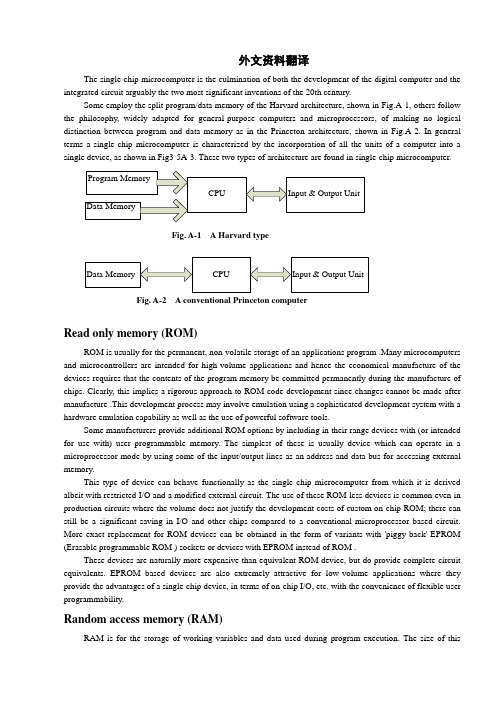
外文资料翻译The single-chip microcomputer is the culmination of both the development of the digital computer and the integrated circuit arguably the two most significant inventions of the 20th century.Some employ the split program/data memory of the Harvard architecture, shown in Fig.A-1, others follow the philosophy, widely adapted for general-purpose computers and microprocessors, of making no logical distinction between program and data memory as in the Princeton architecture, shown in Fig.A-2. In general terms a single-chip microcomputer is characterized by the incorporation of all the units of a computer into a single device, as shown in Fig3-5A-3. These two types of architecture are found in single-chip microcomputer.Program MemoryCPU Input & Output UnitData MemoryFig. A-1 A Harvard typeData Memory CPU Input & Output UnitFig. A-2 A conventional Princeton computerRead only memory (ROM)ROM is usually for the permanent, non-volatile storage of an applications program .Many microcomputers and microcontrollers are intended for high-volume applications and hence the economical manufacture of the devices requires that the contents of the program memory be committed permanently during the manufacture of chips. Clearly, this implies a rigorous approach to ROM code development since changes cannot be made after manufacture .This development process may involve emulation using a sophisticated development system with a hardware emulation capability as well as the use of powerful software tools.Some manufacturers provide additional ROM options by including in their range devices with (or intended for use with) user programmable memory. The simplest of these is usually device which can operate in a microprocessor mode by using some of the input/output lines as an address and data bus for accessing external memory.This type of device can behave functionally as the single chip microcomputer from which it is derived albeit with restricted I/O and a modified external circuit. The use of these ROM less devices is common even in production circuits where the volume does not justify the development costs of custom on-chip ROM; there can still be a significant saving in I/O and other chips compared to a conventional microprocessor based circuit. More exact replacement for ROM devices can be obtained in the form of variants with 'piggy-back' EPROM (Erasable programmable ROM ) sockets or devices with EPROM instead of ROM .These devices are naturally more expensive than equivalent ROM device, but do provide complete circuit equivalents. EPROM based devices are also extremely attractive for low-volume applications where they provide the advantages of a single-chip device, in terms of on-chip I/O, etc. with the convenience of flexible user programmability.Random access memory (RAM)RAM is for the storage of working variables and data used during program execution. The size of thismemory varies with device type but it has the same characteristic width (4,8,16 bits etc.) as the processor ,Special function registers, such as stack pointer or timer register are often logically incorporated into the RAM area. It is also common in Harvard type microcomputers to treat the RAM area as a collection of register; it is unnecessary to make distinction between RAM and processor register as is done in the case of a microprocessor system since RAM and registers are not usually physically separated in a microcomputer.Central processing unit (CPU)The CPU is much like that of any microprocessor. Many applications of microcomputers and microcontrollers involve the handling of binary-coded decimal (BCD) data (for numerical displays, for example) ,hence it is common to find that the CPU is well adapted to handling this type of data .It is also common to find good facilities for testing, setting and resetting individual bits of memory or I/O since many controller applications involve the turning on and off of single output lines or the reading the single line. These lines are readily interfaced to two-state devices such as switches, thermostats, solid-state relays, valves, motor, etc.Parallel input/outputParallel input and output schemes vary somewhat in different microcomputer; in most a mechanism is provided to at least allow some flexibility of choosing which pins are outputs and which are inputs. This may apply to all or some of the ports. Some I/O lines are suitable for direct interfacing to, for example, fluorescent displays, or can provide sufficient current to make interfacing other components straightforward. Some devices allow an I/O port to be configured as a system bus to allow off-chip memory and I/O expansion. This facility is potentially useful as a product range develops, since successive enhancements may become too big for on-chip memory and it is undesirable not to build on the existing software base.Serial input/outputSerial communication with terminal devices is common means of providing a link using a small number of lines. This sort of communication can also be exploited for interfacing special function chips or linking several microcomputers together .Both the common asynchronous synchronous communication schemes require protocols that provide framing (start and stop) information .This can be implemented as a hardware facility or U(S) ART (Universal (synchronous) asynchronous receiver/transmitter) relieving the processor (and the applications programmer) of this low-level, time-consuming, detail. t is merely necessary to selected a baud-rate and possibly other options (number of stop bits, parity, etc.) and load (or read from) the serial transmitter (or receiver) buffer. Serialization of the data in the appropriate format is then handled by the hardware circuit.Timing/counter facilitiesMany application of single-chip microcomputers require accurate evaluation of elapsed real time .This can be determined by careful assessment of the execution time of each branch in a program but this rapidly becomes inefficient for all but simplest programs .The preferred approach is to use timer circuit that can independently count precise time increments and generate an interrupt after a preset time has elapsed .This type of timer is usually arranged to be reloadable with the required count .The timer then decrements this value producing an interrupt or setting a flag when the counter reaches zero. Better timers then have the ability to automatically reload the initial count value. This relieves the programmer of the responsibility of reloading the counter and assessing elapsed time before the timer restarted ,which otherwise wound be necessary if continuous precisely timed interrupts were required (as in a clock ,for example).Sometimes associated with timer is an event counter. With this facility there is usually a special input pin , that can drive the counter directly.Timing componentsThe clock circuitry of most microcomputers requires only simple timing components. If maximum performance is required, a crystal must be used to ensure the maximum clock frequency is approached but not exceeded. Many clock circuits also work with a resistor and capacitor as low-cost timing components or can be driven from an external source. This latter arrangement is useful is external synchronization of the microcomputer is required.Programming languagesHigher level PLC programming languages have been around for some time, but lately their popularity has mushrooming. "As Raymond Leveille, vice president & general manager, Siemens Energy &Automation .inc; Programmable controls are being used for more and more sophisticated operations, languages other than ladder logic become more practical, efficient, and powerful. For example, it's very difficult to write a trigonometric function using ladder logic." Languages gaining acceptance include Boolean, control system flowcharting, and such function chart languages as Graphcet and its variation .And there's increasing interest in languages like C and BASIC.PLCs in process controlThus far, PLCs have not been used extensively for continuous process control .Will this continue? "The feeling that I've gotten," says Ken Jannotta, manger, product planning, series One and Series Six product ,at GE Fanuc North America,'is that PLCs will be used in the process industry but not necessarily for process control."Several vendors -obviously betting that the opposite will happen -have introduced PLCs optimized for process application .Rich Ryan, manger, commercial marketing, Allen-bradley Programmable Controls Div., cites PLCs's increasing use such industries as food ,chemicals ,and petroleum. Ryan feels there are two types of applications in which they're appropriate. "one," he says," is where the size of the process control system that's being automated doesn't justify DCS[distributed control system].With the starting price tags of chose products being relatively high, a programmable controller makes sense for small, low loop count application .The second is where you have to integrate the loop closely with the sequential logical .Batch controllers are prime example ,where the sequence and maintaining the process variable are intertwined so closely that the benefits of having a programmable controller to do the sequential logical outweighs some of the disadvantages of not having a distributed control system."Bill Barkovitz, president of Triconex, predicts that "all future controllers that come out in the process control system business will embrace a lot of more PLC technology and a lot more PLC functionality than they ever did before."Communications and MAPCommunications are vital to an individual automation cell and to be automated factory as a whole. We've heard a lot about MAP in the last few years ,and a lot of companies have jumped on the bandwagon. Many, however, were disappointed when a fully-defined and completed MAP specification didn't appear immediately .Says Larry Komarek: "Right now, MAP is still a moving target for the manufacturers, a specification that is not final .Presently, for example. people are introducing products to meet the MAP2.1standard .Yet2.1-based products will be obsolete when the new standard for MAP3.0 is introduced."Because of this, many PLC vendors are holding off on full MAP implementations. Omron, for example, has an ongoing MAP-compatibility program; but Frank Newburn, vice president of Omron's Industrial Division ,reports that because of the lack of a firm definition ,Omron's PLCs don't yet talk to MAP.Since it's unlikely that an individual PLC would talk to broad MAP anyway, makers are concentrating on proprietary networks. According to Sal Provanzano, users fear that if they do get on board and vendors withdraw from MAP, they'll be the ones left holding a communications structure that's not supported.Universal I/OWhile there are concerns about the lack of compatible communications between PLCs from different vendors, the connection at the other end-the I/O-is even more fragmented .With rare exceptions, I/O is still proprietary .Yet there are those who feel that I/O will eventually become more universal .GE Fanuc is hoping to do that with its Genius smart I/O line. The independent I/O makers are pulling in the same direction.Many say that I/O is such a high-value item that PLC makers will always want to keep it proprietary .As Ken Jannotta, says: "The I/O is going to be a disproportionate amount of the hardware sale. Certainly each PLC vendor is going to try to protect that. "For that reason, he says, PLC makers won't begin selling universal I/O system from other vendor. "if we start selling that kind of product, "says jannotta, "what do we manufacture?"With more intelligent I/O appearing, Sal Provanzano feels this will lead to more differentiation among I/O from different makers. "Where the I/O becomes extremely intelligent and becomes part of the system, "he says, "it really is hard to define which is the I/O and which is CPU. It really CPU, if you will, is equally integrated into the system as the I/O."Connecting PLC I/O to PCsWhile different PLCs probably will continue to use proprietary I/O, several vendors make it possible to connect5 their I/O to IBM PC-compatible equipment. Alle-bradeley, Could, and Cincinnati Milacron already have, and rumor has it that GE is planning something along these same lines .[4]Bill Ketelhut, manage of product planning at GE Fanuc North America ,sees this sort of thing as alternative to universal I/O."I think the trend ,instead of twoard universal I/O, will be multiple host interface ," he says .Jodie Glore ,director of marking, Square D Automation Products, Views it as another indication that PLCs are, and have been for some time, industrial computers.中文译文单片机是电脑和集成电路发展的巅峰,有据可查的是他们也是20世纪最有意义的两大发明。
- 1、下载文档前请自行甄别文档内容的完整性,平台不提供额外的编辑、内容补充、找答案等附加服务。
- 2、"仅部分预览"的文档,不可在线预览部分如存在完整性等问题,可反馈申请退款(可完整预览的文档不适用该条件!)。
- 3、如文档侵犯您的权益,请联系客服反馈,我们会尽快为您处理(人工客服工作时间:9:00-18:30)。
外文资料翻译From the world of radio in the world to a single chipModern computer technology, industrial revolution, the world economy from the capital into the economy to knowledge economy. Field in the electronic world, from the 20th century into the era of radio to computer technology in the 21st century as the center of the intelligent modern era of electronic systems. The basic core of modern electronic systems are embedded computer systems (referred to as embedded systems), while the microcontroller is the most typical and most extensive and most popular embedded systems.First, radio has created generations of excellence in the worldFifties and sixties in the 20th century, the most representative of the advanced electronic technology is wireless technology, including radio broadcasting, radio, wireless communications (telegraph), Amateur Radio, radio positioning, navigation and other telemetry, remote control, remote technology. Early that these electronic technology led many young people into the wonderful digital world, radio show was a wonderful life, the prospects for science and technology. Electronics began to form a new discipline. Radio electronics, wireless communications began e-world journey. Radio technology not only as a representative of advanced science and technology at that time, but also from popular to professional fields of science, attracting the young people and enable them to find a lot of fun. Ore from the bedside to the superheterodyne radio radio; report issued from the radio amateur radio stations; from the telephone, electric bell to the radio control model. Became popular youth radio technology, science and technology education is the most popular and most extensive content. So far, many of the older generation of engineers, experts, Professor of the year are radio enthusiasts. Fun radio technology, radio technology, comprehensive training, from basic principles of electronics, electronic components to the radio-based remote control, telemetry, remote electronic systems, has trained several generations of technological excellence.Second, from the popularity of the radio era to era of electronic technologyThe early radio technology to promote the development of electronic technology, most notably electronic vacuum tube technology to semiconductor electronic technology. Semiconductor technology to realize the active device miniaturization and low cost, so more popular with radio technology and innovation, and to greatly broaden the number of non-radio-control areas.The development of semiconductor technology lead to the production of integrated circuit, forming the modern electronic technology leap from discrete electronics into the era of era of integrated circuits. Electronic design engineers no longer use the discrete electronic components designed circuit modules, and direct selection of integrated circuit components constitute a single system. They freed the design of the circuit unit dedicated to system design, greatly liberating the productive forces of science and technology, promote the wider spread of electronic systems.Semiconductor integrated circuits in the basic digital logic circuits first breakthrough.A large number of digital logic circuits, such as gates, counters, timers, shift registers, and analog switches, comparators, etc., for the electronic digital control provides excellent conditions for the traditional mechanical control to electronic control. Power electronic devices and sensor technology to make the original to the radio as the center of electronic technology turned to mechanical engineering in the field of digital control systems, testing in the field of information collection, movement of electrical mechanical servo drive control object.Semiconductor and integrated circuit technology will bring us a universal age of electronic technology, wireless technology as the field of electronic technology a part of.70 years into the 20th century, large scale integrated circuit appeared to promote the conventional electronic circuit unit-specific electronic systems development. Many electronic systems unit into a dedicated integrated devices such as radios, electronic clocks, calculators, electronic engineers in these areas from the circuit, the system designed to debug into the device selection, peripheral device adapter work. Electronic technology, and electronic products enriched, electronic engineers to reduce the difficulty, but at the same time, radio technology, electronic technology has weakened the charm. The development of semiconductor integrated circuits classical electronic systems are maturing, remain in the large scale integrated circuit other than the shrinking of electronic technology, electronic technology is not the old days of radio fun times and comprehensive engineering training.Third, from the classic era of electronic technology to modern electronic technology of the times80 years into the 20th century, the century of economic change is the most important revolution in the computer. The computer revolution in the most important sign is the birth of the computer embedded applications. Modern computer numerical requirements should be born. A long period of time, is to develop the massive computer numerical duty. But the computer shows the logic operation, processing, control, attracting experts in the field of electronic control, they want development to meet the control object requirements of embedded applications, computer systems. If you meet the massive data-processing computer system known as general-purpose computer system, then the system can be the embedded object (such as ships, aircraft, motorcycles, etc.) in a computer system called the embedded computer. Clearly, both the direction of technology development are different. The former requires massive data storage, handling, processing and analysis of high-speed data transmission; while the latter requires reliable operation in the target environment, the external physical parameters on high-speed acquisition, analysis and processing logic and the rapid control of external objects. It will add an early general-purpose computer data acquisition unit, the output driver circuit reluctance to form a heat treatment furnace temperature control system. This general-purpose computer system is not possible for most of the electronic system used, and to make general-purpose computer system meets therequirements of embedded applications, will inevitably affect the development of high-speed numeric processing. In order to solve the contradiction between the development of computer technology, in the 20th century 70s, semiconductor experts another way, in full accordance with the electronic system embedded computer application requirements, a micro-computer's basic system on a chip, the formation of the early SCM (Single Chip Microcomputer). After the advent of single chip in the computer industry began to appear in the general-purpose computer systems and embedded systems the two branches. Since then, both the embedded system, or general-purpose computer systems have been developed rapidly. Although the early general-purpose computer converted the embedded computer systems, and real embedded system began in the emergence of SCM. Because the microcontroller is designed specifically for embedded applications, the MCU can only achieve embedded applications. MCU embedded applications that best meet environmental requirements, for example, chip-level physical space, large-scale integrated circuits low-cost, good peripheral interface bus and outstanding control of instruction.A computer system microcontroller core, embedded electronic systems, intelligent electronic systems for the foundation. Therefore, the current single chip electronic system in widespread use of electronic systems to enable rapid transition to the classical modern intelligent electronic systems.从无线电世界到单片机世界现代计算机技术的产业革命,将世界经济从资本经济带入到知识经济时代。