ERNOSTAR镜头课程设计
镜头课程设计

镜头课程设计一、教学目标本课程的教学目标是使学生掌握光学的基本原理和实验技能,培养学生的观察能力和科学思维。
知识目标包括:理解光的传播、反射、折射和衍射等基本现象;掌握光的波动说、粒子说和量子力学基础。
技能目标包括:能够运用光学知识分析和解决实际问题;能够进行简单的光学实验设计和操作。
情感态度价值观目标包括:培养学生的科学精神和创新意识;增强学生对光学科学的兴趣和热爱。
二、教学内容本课程的教学内容主要包括光学基本原理、光的传播与反射、光的折射与衍射、光的波动说与粒子说、量子力学基础等。
具体安排如下:1.光学基本原理:光的传播、反射、折射和衍射等基本现象的定义和规律。
2.光的传播与反射:光的传播速度、介质的折射率、反射定律和折射定律等。
3.光的折射与衍射:折射率的概念和计算、全反射和临界角、光的衍射现象和衍射条件等。
4.光的波动说与粒子说:波动说的基本原理、光的干涉现象和双缝干涉实验、光的偏振现象和马吕斯定律等;粒子说的基本原理、普朗克能量量子化和黑体辐射问题、光电效应和康普顿效应等。
5.量子力学基础:波函数和薛定谔方程、海森堡不确定性原理和测不准原理、泡利不相容原理和能级公式、电子的轨道和能级等。
三、教学方法本课程的教学方法包括讲授法、讨论法、案例分析法、实验法等。
通过多样化的教学方法,激发学生的学习兴趣和主动性。
具体方法如下:1.讲授法:教师通过讲解和演示,系统地传授光学基本原理和实验技能。
2.讨论法:教师引导学生进行思考和讨论,培养学生的科学思维和问题解决能力。
3.案例分析法:教师通过分析具体的案例,帮助学生理解和应用光学知识。
4.实验法:教师学生进行实验操作,培养学生的实验技能和观察能力。
四、教学资源本课程的教学资源包括教材、参考书、多媒体资料、实验设备等。
具体资源如下:1.教材:选用《光学原理》等权威教材,系统地介绍光学基本原理和实验方法。
2.参考书:提供《光学》等参考书籍,供学生深入学习和拓展知识。
ZEMAX课程设计心得照相机物镜设计【模版】
ZEMAX课程设计——照相机物镜设计一、(课题的背景知识,如照相机镜头的发展概况,类型及其主要技术参数的简要说明)二、课程设计题目设计一个照相物镜,1)光学特性要求:f’=100mm;2=30;;D/f’=1:3.5.2)成像质量要求:弥散斑直径小于0.05mm;倍率色差最好不超过0.01mm;畸变小于3%。
三、设计课题过程1、参考Ernostar和Tessar联合型物镜设计相关数据,对其进行相关改进。
Ernostar和Tessar联合型物镜设计相关数据如下表1(其中焦距f’=75.68mm;相对孔径D Radius/r Thickness/d 折射率/n 玻璃阿贝数/ν38.339 3.57 1.71289 53.950.988 0.3235.192 5.49 1.71289 53.9197.94 4.83-96.144 1.87 1.6362 35.326.53 8-1074.1 1.38 1.53246 45.937.053 7.6-49.135 1.72904 54.8表12、根据焦距曲率镜片厚度之间的比例关系,即f1/f2=r1/r2=d1/d2,得到焦距100mm,相Radius/r Thickness/d 折射率/n 玻璃阿贝数/ν50.659 4.717 1.71289 53.967.373 0.42346.501 7.254 1.71289 53.9261.548 6.382-127.040 2.471 1.6362 35.335.055 10.571-1419.262 1.824 1.53246 45.948.960 10.042-64.925 1.72904 54.8表23、启动ZEMAX,将表1数据输入到LDE,相关步骤由以下图给出(1)打开ZEMAX。
(2)输入数据。
在主选单system下,圈出wavelengths,依喜好键入所要的波长,同时可选用不同波长,本实验中在第一列键入0.486,单位为microns,第二第三列分别键入0.587、0.656。
多波长广角f-theta透镜光学设计
2 0 1 7年 7月
应
用
光
学
Vo 1 . 3 8 NO . 4
J o u r n a l o f App l i e d Op t i c s
J u 1 .2 0 1 7
文章 编 号 : 1 0 0 2 — 2 O 8 2 ( 2 O 1 7 ) 0 4 一 O 5 3 3 一 O 5
p r o p e r t i e s . Th e f i n a l d e s i g n r e s u l t s h o ws t h a t t h e l a t e r a l c o l o r i s l e s s t h a n 3 t i m ,t h e c a l i b r a t e d f - Th e t a d i s t o r t i o n s a r e a l l l e s s t h a n 0 . 0 1 5 a n d t h e e n e r g y u t i l i z a t i o n r a t e i s n e a r l y 9 0 , wh i c h
t i on c or r e c t i o n i s c a r r i e d out b y u s i ng t he o pt i c a l po we r d i s t r i b ut i o n wi t h di f f e r e nt d i s pe r s i o n
多波长广 角 f - t h e t a透 镜 光 学 设 计
周 燕 , 沈 涛
( 哈尔滨理工大学 , 黑龙江 哈尔滨 1 5 0 0 8 0 )
摘 要 : f - t h e t a 透 镜作 为激 光 扫描 系统 中必不 可 少的部 件 , 对 系统 工作 面尺寸 、 测量速度、 测 量精
ZEMAX课程设计——照相机物镜设计
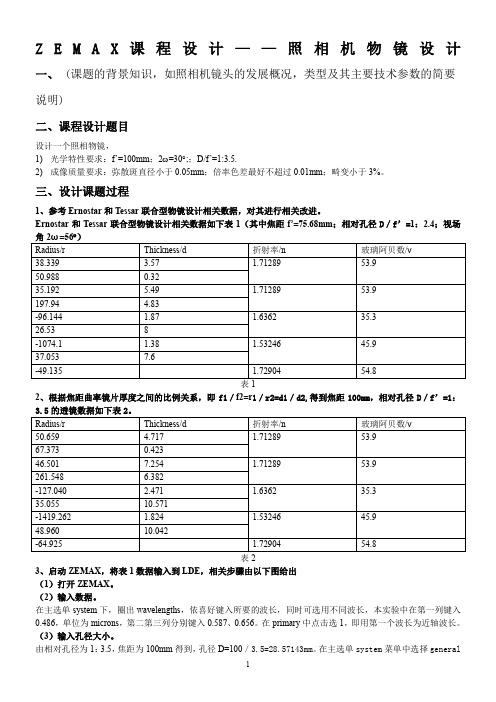
Z E M A X课程设计——照相机物镜设计一、(课题的背景知识,如照相机镜头的发展概况,类型及其主要技术参数的简要说明)二、课程设计题目设计一个照相物镜,1)光学特性要求:f’=100mm;2ω=30︒;;D/f’=1:3.5.2)成像质量要求:弥散斑直径小于0.05mm;倍率色差最好不超过0.01mm;畸变小于3%。
三、设计课题过程1、参考Ernostar和Tessar联合型物镜设计相关数据,对其进行相关改进。
Ernostar和Tessar联合型物镜设计相关数据如下表1(其中焦距f’=75.68mm;相对孔径D/f’=1:2.4;视场表12、根据焦距曲率镜片厚度之间的比例关系,即f1/f2=r1/r2=d1/d2,得到焦距100mm,相对孔径D/f’=1:3.5的透镜数据如下表2。
3、启动ZEMAX,将表1数据输入到LDE,相关步骤由以下图给出(1)打开ZEMAX。
(2)输入数据。
在主选单system下,圈出wavelengths,依喜好键入所要的波长,同时可选用不同波长,本实验中在第一列键入0.486,单位为microns,第二第三列分别键入0.587、0.656。
在primary中点击选1,即用第一个波长为近轴波长。
(3)输入孔径大小。
由相对孔径为1:3.5,焦距为100mm得到,孔径D=100/3.5=28.57143mm。
在主选单system菜单中选择generaldata,在aper value上键入28.57143。
(4)输入视场角。
(5)输入曲率,面之间厚度,玻璃材质。
本实验中共有5组透镜,其中最后两组为双胶合透镜,故共有9个面,回到LDE,可以看到三个surface,STO (孔径光阑)、OBJ(物点或光源)、IMA(像屏),在STO前后插入几组surface,除IMA外共计9组surface,输入数据。
最后根据参考实验图确定STO在第6面上。
①点击layout,画出2D图形②点击spot diagram ,画出点阵图由图看出光波在波长1、2、3下的弥散斑直径大小分别为33.625、54.419、64.768(单位:微米),其中第2、3波长弥散斑大小大于50微米,不符合要求,故需要改进。
ERNOSTAR镜头课程设计

目录1.课程设计的背景及意义 (2)2.设计的基本原理 (3)3.课程设计的基本过程 (5)4.设计的结果 (8)5.镜头的优化 (11)6.总结和结论 (14)7.参考文献 (15)1.课程设计的背景及意义随着光学产业的迅速发展,各类光学器件都在不同程度的改变和影响着我们的生活,基于ZEMAX的摄影镜头设计便是十分重要的一部分,任何一个光学系统不管应用于和处,其作用都是把目标发出的光透过我们所设计的镜头,最后成像,光学镜头的好坏直接影响着成像系统的成像质量,基于柯克三合系统的镜头结构,能够对光学镜头所有六种像差进行校正的结构最简单摄影镜头,故而为世界各光学公司仿制,加之三片三组式柯克结构镜头成本低廉故而产量巨大,广泛应用于各中低档相机镜头之中。
通过对光学镜头的设计也是我们对与镜头设计有关的各类参数有更深的了解。
我负责查找ERNOSTAR镜头的基本结构以及应用参数,ERNOSTAR在摄影史上是具有划时代意义的摄影头,它的最大光圈在标准相机上可以达到2.0,要知道在1927年Tessar的光圈也就只有设计到2.7。
ERNOSTAR是当时第一支可以在光线条件较差的情况下使用的镜头,也是第一个可以在很差的光线下不使用三脚架的镜头。
因此了解它的工作原理以及特性对于我今后的学习有着十分重大的意义。
图1 生产研发ERNOSTAR镜头的ERNEMANN公司2.设计的基本原理基于柯克三合系统的镜头结构,需要设计出5种镜头,包括典型cooke-triple结构镜头、ERNOSTAR结构镜头、Tessar结构镜头Heliar结构镜片、sonnar 结构镜头。
2.1照相物镜的光学特性(1)焦距f'决定了所成像的大小,当物体处于有限距离像高y'=(1-β)f'tan w,β是垂轴放大率。
物距L都比较大,所以f'=L'。
(2)相对孔径照相物镜的相对孔径决定其受衍射限制的最高分辨率和相面光照度。
这里N=D/ f'/λ,(3)视场角照相物镜的视场角决定其在接收器上成清晰像的空间范围,按视场角的大小,照相物镜分为:小视场物镜,中视场物镜,广角物镜,超广角物镜。
光学课程设计瞄准镜

光学课程设计 瞄准镜一、课程目标知识目标:1. 让学生理解并掌握光学基础知识,特别是光的传播、反射和折射原理。
2. 使学生了解瞄准镜的光学构成,包括透镜、反射镜等,并掌握其工作原理。
3. 引导学生掌握瞄准镜在军事、射击运动中的应用及其重要性。
技能目标:1. 培养学生运用光学知识分析瞄准镜中光路的能力,提高实际问题解决技能。
2. 通过实际操作,让学生学会调整和使用瞄准镜,提升操作精确性和效率。
3. 培养学生的团队合作能力,通过小组讨论和实验,增强问题分析和解决过程中的沟通技巧。
情感态度价值观目标:1. 激发学生对光学知识的兴趣,培养其探索科学奥秘的热情。
2. 培养学生严谨、细心的学习态度,使其在学习和实践中认识到精确与细节的重要性。
3. 强化学生的国家安全意识,了解科学技术在国家防务和射击运动中的重要作用。
课程性质:本课程为物理学科的光学部分,结合实际应用,以瞄准镜为载体,深入浅出地讲解光学知识。
学生特点:考虑到学生所在年级的特点,课程内容将结合中学生认知水平和兴趣点,注重理论与实践相结合。
教学要求:课程要求学生在掌握光学基础知识的基础上,通过实际操作和团队合作,提高问题分析和解决能力,培养科学精神和爱国情怀。
通过具体的学习成果分解,教师可进行针对性的教学设计和评估。
二、教学内容1. 光学基础知识:- 光的传播、反射和折射原理- 透镜、反射镜的类型及作用- 光路图绘制与分析2. 瞄准镜光学构成:- 瞄准镜的结构及工作原理- 透镜、反射镜在瞄准镜中的应用- 瞄准镜的视场、放大率和分辨率等参数介绍3. 瞄准镜的应用:- 瞄准镜在军事领域的应用- 瞄准镜在射击运动中的作用- 瞄准镜使用注意事项及维护保养4. 实践操作:- 瞄准镜的组装与拆解- 瞄准镜的调校与使用- 实际射击体验与问题分析教学大纲安排:第一课时:光学基础知识学习第二课时:瞄准镜光学构成及工作原理第三课时:瞄准镜的应用及实践操作第四课时:瞄准镜的调校、使用及问题分析教学内容与课本关联性:本教学内容与物理课本中光学章节相关,结合瞄准镜的实际应用,使学生在掌握光学知识的同时,了解其在实际中的应用。
ERNOSTAR镜头课程设计

ERNOSTAR镜头课程设计目录1.课程设计的背景及意义 (2)2.设计的基本原理 (3)3.课程设计的基本过程 (5)4.设计的结果 (8)5.镜头的优化 (11)6.总结和结论 (14)7.参考文献 (15)1.课程设计的背景及意义随着光学产业的迅速发展,各类光学器件都在不同程度的改变和影响着我们的生活,基于ZEMAX的摄影镜头设计便是十分重要的一部分,任何一个光学系统不论应用于和处,其作用都是把目标发出的光透过我们所设计的镜头,最后成像,光学镜头的好坏直接影响着成像系统的成像质量,基于柯克三合系统的镜头结构,能够对光学镜头所有六种像差进行校正的结构最简单摄影镜头,故而为世界各光学公司仿制,加之三片三组式柯克结构镜头成本低廉故而产量巨大,广泛应用于各中低档相机镜头之中。
经过对光学镜头的设计也是我们对与镜头设计有关的各类参数有更深的了解。
我负责查找ERNOSTAR镜头的基本结构以及应用参数,ERNOSTAR在摄影史上是具有划时代意义的摄影头,它的最大光圈在标准相机上能够达到2.0,要知道在1927年Tessar的光圈也就只有设计到 2.7。
ERNOSTAR是当时第一支能够在光线条件较差的情况下使用的镜头,也是第一个能够在很差的光线下不使用三脚架的镜头。
因此了解它的工作原理以及特性对于我今后的学习有着十分重大的意义。
图1 生产研发ERNOSTAR镜头的ERNEMANN公司2.设计的基本原理基于柯克三合系统的镜头结构,需要设计出5种镜头,包括典型cooke-triple结构镜头、ERNOSTAR结构镜头、Tessar结构镜头Heliar结构镜片、sonnar结构镜头。
2.1照相物镜的光学特性(1)焦距f'决定了所成像的大小,当物体处于有限距离像高y'=(1-β)f'tan w,β是垂轴放大率。
物距L都比较大,因此f'=L'。
(2)相对孔径照相物镜的相对孔径决定其受衍射限制的最高分辨率和相面光照度。
尼克尔镜头基础知识PPT课件

光圈与快门速度的搭配
光圈和快门速度是摄影中两个重要的曝光参数。光圈控制 镜头的进光量,而快门速度控制曝光时间。
尼克尔镜头具有较大的光圈范围,从f/1.8到f/22,为摄影师 提供了更大的灵活性。摄影师可以根据拍摄需求选择合适的 光圈与快门速度的搭配,以获得所需的曝光效果和景深控制。
04
尼克尔镜头的分类与选择
然风光和城市景色。
尼克尔镜头的高成像质量 和大光圈设计适合拍摄清 晰、立体的人像照片。
尼克尔镜头的快速对焦和稳 定性能使它成为捕捉运动瞬
间和体育赛事的首选。
02
尼克尔镜头的基本结构
前组镜片
前组镜片是尼克尔镜头的第一片镜片,位于镜头 最前端,主要用于收集光线并初步校正像差。
前组镜片通常采用球面或非球面设计,以适应不 同的光线收集和校正需求。
尼克尔镜头基础知识
• 尼克尔镜头简介 • 尼克尔镜头的基本结构 • 尼克尔镜头的光学性能 • 尼克尔镜头的分类与选择 • 尼克尔镜头的维护与保养
01
尼克尔镜头简介
尼克尔镜头的历史与发展
19世纪末期,尼克尔镜头由德 国光学公司卡尔·蔡司推出,成 为最早的商用摄影镜头之一。
20世纪初,尼克尔镜头逐渐发 展成为世界范围内广泛使用的 摄影镜头品牌。
02
长焦镜头一般用于拍摄野生动物、运动等需要远距离拍摄的场
景。
长焦镜头的光圈较大,可以在低光条件下获得较好的成像质量。
03
微距镜头
微距镜头是指能够近距离拍摄细微物 体的镜头,其放大倍率较高,可以展 现出被摄物体的细节。
微距镜头一般用于拍摄昆虫、花卉等 需要展现细节的场景。
05
尼克尔镜头的维护与保养
尼克尔镜头采用先进的光学设计,控制畸变,确保图像的几何形状准确。这样, 摄影师可以在拍摄时更加专注于构图和创意表达,而不必担心畸变问题。
创意镜头解析课程设计

创意镜头解析课程设计一、课程目标知识目标:1. 学生能理解并掌握创意镜头的基本概念,如景别、角度、运动等。
2. 学生能分析并解读不同创意镜头在影视作品中的应用及其效果。
3. 学生能了解创意镜头在表达主题、情感及故事节奏中的作用。
技能目标:1. 学生能运用所学的创意镜头知识,进行独立拍摄和剪辑,创作具有个性的短视频。
2. 学生能在团队协作中发挥个人特长,与他人共同完成拍摄任务,提高沟通与协作能力。
3. 学生能通过实践,掌握运用创意镜头提升影视作品质量的方法。
情感态度价值观目标:1. 学生培养对影视艺术的热爱和兴趣,提高审美能力。
2. 学生在学习过程中,培养创新思维和勇于尝试的精神。
3. 学生通过创意镜头的学习,学会尊重他人观点,培养团队协作精神。
本课程针对初中年级学生,结合学科特点,注重理论与实践相结合。
在教学过程中,充分考虑学生的年龄特点,注重启发式教学,激发学生兴趣,培养其创新能力和团队协作能力。
课程目标具体、可衡量,旨在帮助学生掌握创意镜头相关知识,提高其影视创作技能,同时培养其健康的情感态度和价值观。
为实现课程目标,后续教学设计和评估将围绕具体学习成果展开。
二、教学内容1. 创意镜头基本概念:景别(远景、全景、中景、近景、特写)、角度(平视、仰视、俯视)、运动(推拉、摇移、跟拍)等。
教学安排:1课时,教材第2章。
2. 创意镜头的应用与效果:分析不同镜头在影视作品中的运用,探讨其表达效果和情感传递。
教学安排:2课时,教材第3章。
3. 创意镜头在影视作品中的作用:讲述创意镜头如何表达主题、情感及故事节奏。
教学安排:1课时,教材第4章。
4. 短视频创作实践:学生分组进行拍摄和剪辑,运用所学创意镜头知识创作作品。
教学安排:4课时,教材第5章。
5. 创意镜头在团队协作中的应用:讨论如何在团队中发挥个人特长,共同完成拍摄任务。
教学安排:1课时,教材第6章。
教学内容根据课程目标进行选择和组织,确保科学性和系统性。
创意镜头解析课程设计

创意镜头解析课程设计一、教学目标本课程的教学目标是让学生掌握创意镜头的基本概念、原理和应用方法。
通过本课程的学习,学生将能够:1.知识目标:了解创意镜头的定义、分类和特点;掌握创意镜头的拍摄技巧和方法;了解创意镜头在电影、广告和摄影等领域的应用。
2.技能目标:能够运用创意镜头的原理和技巧进行拍摄和创作;能够分析和评价创意镜头的效果和价值。
3.情感态度价值观目标:培养学生对创意镜头的兴趣和热爱,提高学生对电影、广告和摄影等领域的鉴赏能力;培养学生勇于创新、追求卓越的精神风貌。
二、教学内容本课程的教学内容主要包括以下几个部分:1.创意镜头的基本概念:介绍创意镜头的定义、分类和特点,使学生了解创意镜头的基本知识。
2.创意镜头的拍摄技巧:讲解和演示创意镜头的拍摄方法和技巧,引导学生学会运用创意镜头进行拍摄。
3.创意镜头的应用案例:分析电影、广告和摄影等领域中的创意镜头应用实例,使学生了解创意镜头在实际创作中的作用和价值。
4.创意镜头的创作实践:学生进行创意镜头的拍摄和实践,培养学生的创新能力和实际操作能力。
三、教学方法为了实现本课程的教学目标,我们将采用以下教学方法:1.讲授法:通过讲解和演示,向学生传授创意镜头的基本知识和拍摄技巧。
2.讨论法:学生进行案例分析和创作实践,引导学生主动思考和探索,提高学生的创新能力和鉴赏能力。
3.案例分析法:分析电影、广告和摄影等领域中的创意镜头应用实例,使学生了解创意镜头在实际创作中的作用和价值。
4.实验法:学生进行创意镜头的拍摄和实践,培养学生的实际操作能力和创新精神。
四、教学资源为了支持本课程的教学内容和教学方法的实施,我们将准备以下教学资源:1.教材:选用权威、实用的教材,为学生提供系统的创意镜头知识体系。
2.参考书:提供相关的参考书籍,丰富学生的知识储备。
3.多媒体资料:收集和制作创意镜头的实例视频、图片等多媒体资料,直观地展示创意镜头的原理和效果。
4.实验设备:准备摄影器材、剪辑软件等实验设备,为学生提供实践操作的机会。
新式施威夫斯比格勒式光学望远镜设计说明书
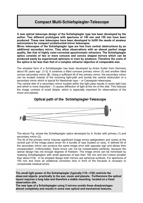
A new optical telescope design of the Schiefspiegler type has been developed by the author. Two different prototypes with apertures of 140 mm and 150 mm have been produced. These new telescopes have been developed to fulfill the needs of amateur astronomers for compact unobstructed mirror telescopes.Mirror telescopes of the Schiefspiegler type are free from central obstructions by an additional secondary mirror. They allow observations with an almost perfect image quality, like that of highly color-corrected apochromatic refractors. The Schiefspiegler optics consists of two or more concave and convex shaped mirrors which can be produced easily by experienced opticians or even by amateurs. Therefore the costs of the optics is far less than that of a complex refractor objective of comparable size.The simplest form of a Schiefspiegler has been developed by Anton Kutter from Germany about 60 years ago [1-3]. It conbines a tilted concave primary mirror (1) and another tilted convex secondary mirror (2). Using a sufficient tilt of the primary mirror, the secondary mirror can be located outside of the incoming light-path and avoids the central obstruction of a secondary mirror which is typical for Newtonian type - or Cassegrain telescopes.The central disk of a secondary mirror located within the light pass results in some light loss and which is more important – it causes diffraction of light at the rim of the disk. This reduces the image contrast of small details, which is especially important for observations of the moon and planets.Optical path of the Schiefspiegler-TelescopeThe above Fig. shows the Schiefspiegler optics developed by A. Kutter with primary (1) and secondary mirror (2).The tilt of the primary mirror induces significant image errors (astigmatism and coma) at the central part of the image plane (even for a bundle of rays located on axis). A defined tilt of the secondary mirror can produce the same image error with opposite sign and allows their compensation. Unfortunately, these errors can not be compensated perfectly, because the optical design has not enough degrees of freedom. The image errors can be minimised by realising Schiefspieglers with small apertures of less than 150 mm and low f-ratios (smaller than about f/18). In its simplest design both mirrors use spherical surfaces. For apertures of 150 mm and more an additional correction lens in front of the focusser is necssary to compensate residual errors.The optics of the Multi-Schiefspiegler uses three mirrors. One of them is used twice to realise a total of 4 reflections. The additional degrees of freedom in the optical design allow to compensate the image errors perfectly on axis. Even for 0.5° field of view a diffraction limited image quality is obtained. It is possible to construct compact Schiefspieglers with medium light power (up to f/10) which have rather large apertures. These telescopes can be used for almost all types of astronomical objects. The compactness of the tube allows to transport them to favourable observation sites.The optical system of the Multi-Schiefspiegler uses the secondary mirror twice, it carries the second (2) and the fourth reflection (4). This mirror has to be about 6-20% larger in diameter than the primary mirror (1), depending on the optical layout. The concave primary (1) and the convex secondary mirror (2. and 4. reflection) use spherical surfaces and the third mirror (3) is parabolic. The image plane (F) is located sideways behind the primary mirror. The resulting image plane tilt amounts to 1.4° - 2° and can be neglected visually. The image distortion is less than 1.2%.The numbers in the Fig. above describe the sequence of reflections. Only the marginal light-rays within the telescope´s plane of symmetry (saggital plane) are shown. The centre of the fourth reflection (4) is shifted with respect to the second reflection (2) along the symmetry plane. This is necessary to make the final image plane accessible to the observer at position F .The f-ratio of the optical system is determined by the focal length of the parabolic mirror. A conic constant k = 0 defines a spherical curve of the mirror and k = -1 a parabolic curve (see table below).The optical layout (Design 1) for a Multi-Schiefspiegler with an aperture of 150 mm and a corresponding f-ratio f/10.9 was calculated and the data were shown in the table. The corresponding spot-diagram for 0.5° field of view was displaced below.spot-diagram (design 1)The corresponding geometrical and optical data for design 1 are shown in the table below. Reflection No. 4 denotes the additional reflection on the secondary mirror. The mirror diameters in brackets are necessary to ensure an unvignetted field of view of 0.5°. Due to the extension of the illuminated areas and the separation of their centres (of the second and fourth reflection) a secondary mirror is needed, which is about 9% larger than the aperture. By using a standard sized secondary mirror of 150 mm in diameter the aperture has to be restricted to a diameter of 144 mm. Nevertheless the aperture can be extended to 150 mm resulting in more light and resolution of objects which are centred within the field of view (these central rays are unvignetted).Since the optical system of the Multi-Schiefspiegler uses only spherical and parabolic mirrors they could be commercially produced without serious problems. Amateur telescope makers can produce their own optics and are encouraged in doing so. One has to take into account that the surface accuracy of each mirror should be doubled compared to that of a single mirror optic (Newton telescope) which fulfills the Rayleigh criteria [3]. Otherwise a higher amount of wavefront distortion might be the result, which limits the optical performance of the telescope.spot-diagram (design 2)spot-diagram (design 3)Data of the Multi-Schiefspiegler designs (No. 1 - 3)Design No. aperture f-ratio focal lengthNo. of reflectionmirror diameterradius of mirrorDistance to the next surfacemirror tilt conic constant1 1 150(144)-7205 533 -9° 0 1502 150(132)7205 503 +8.5° 0 f/10.9 3 150(132)-2400 513 +2.8° -1 1637 mm4 (81) 7205 749 -14.5° 0 2 1 150(145)-7205 462 -10.3° 0 150 2 150(135)7205 437 +9.6° 0 f/9.2 3 135 -2100 447 +2.85° -1 1383 mm4 (81) 7205 662 -15.7° 0 3 1 200 (189) - 10000 800 -8.0° 0 200 2 200 (175)10000 785 +7.8° 0 f/12.5 3 200 (175)- 3600 799 +2.6° -1 2493 mm4 (104) 100001071 -13.5° 0The designs given above are only examples of optical layouts. Other layouts may result in a more optimised design.All lengths are given in mm.(diameter) describes the diameter of the illuminated area of the corresponding mirror which is necessary for an unvignetted field of view of 0.5°The f-ratios belong to the free aperture of the primary mirror and are only valid for images near the field centre. This value is slightly reduced off-centre.Negative radii describe concave mirrors, positive values denote convex mirrors. The angle of reflection is twice the mirror tilt.The conic constant k describes the surace figure of the mirror and is defined as k = - (eccentricity)2. k = 0 describes a spherical and k = -1 a parabolic mirror.Two prototypes of the Multi-Schiefspiegler design with 150 mm aperture and f-ratios of f/10.9 and f/9.2 have been realised and were tested at the stars and interferometrically (they correspond to design No. 1 and No. 2). The optics consists of commercially produced mirrors of 150 mm diameter each, made from Duran or Pyrex glass. The image below shows a prototype with f/10.9 on a simple mounting. The tube is adapted to a fork made of aluminium and placed above the declination shaft of the mounting. The centre of gravity of the tube should be balanced above the declination axis. This special adapter avoids the counterweight of the German type mounting. This construction is sometimes used for Schiefspieglers. The disadvantage of this adaptation is, however, that not all regions of thesky could be reached. Alternatively, the tube can be attached by the usual way at the front end of the declination axis. Therefore an aluminium plate is attached at the underside of the tube which can be attached individually to different types of mountings. The mounting should be stable enough to carry the weight of the telescope tube which amounts to 10 –12 kg for design No. 1 and No. 2.The table below gives a technical description of the telescopes realised so far, which correspond to design No. 1 and No. 2 :CharacteristicsDesign 1Design 2Aperture/ f-ratio/focal length150 mm / 10.9 / 1673 mm150 mm / 9.2 / 1384 mm Dimensions of the tube(L x B1/B2 x T) (mm)700 x 380/480 x 200 620 x 370/450 x 200 Weight of tube assemblyApprox. 12 kg Approx. 10 kg Composition of the tubeframeSteal profile combined with front plates made of aluminium steal profile combined with front plates made of aluminium Outer tube materialaluminium plates, 1 mm thickness aluminium plates, 1 mm thickness Mirror cells3 aluminium cells, fully adjustable 3 aluminium cells, fully adjustable Focuser2” Precision focuser with 1.25“ adapter tube, about 100 mm way of travel 2” Precision focuser with 1.25“ adapter tube, about 100 mm way of travelMirror optics2 spherical and 1 parabolic mirror of 150 mm diameter made of Duran or Pyrex glass 2 spherical and 1 parabolic mirror of 150 mm diameter made of Duran or Pyrex glassReflective coating of mirrors enhanced aluminium coating with 94 % reflection enhanced aluminium coating with94 % reflection Reduction of stray-lightsystem of baffles and rough black inner coating system of baffles and rough black inner coating FinderFinderscope or Telrad to be mounted at the topside Finderscope or Telrad to be mounted on the topside.B1 describes the width of the tube on the front side and B2 on the back side.The fully description of adjustment is given in a separate adjustment manual. The following part describes only the general procedure to give an overview.New mirror cells have been developed to allow a final adjustment during observations or on the optical bench. The final compensation of image errors is achieved by small mirror tilts within the telescope´s plane of symmetry (saggital plane) and the direction perpendicular to it (meridional plane). The mirror cells allow a pre-adjustment at 3 points by turning corresponding nuts on bolts. The pre-adjustment can be performed by the help of a laser pointer which is located at the center of the aperture. For this purpose the tube is opened to have acess to all mirrors.. This procedure and final adjustments by using a bright star are described in the adjustment manual. Optical calculations [4] show that remaining image errors can be compensated perfectly by small tilt changes of the first, second and third mirror within the saggital and meridional plane. This is realised by attaching the cells to a hinge type fork mounted to the frame. Two adjustment screws for each mirror allow for small tilts and can be reached from the outside of the tube (2 at the frontside and 4 at the backside).Pre-adjustment of the mirrors is performed by mounting the laser pointer centred within the aperture stop. The laser beam should reach the primary, secondary and tertiary mirror at their centres. The primary mirror is tilted a little bit further within the saggital plane and should reach the secondary a distance of 10mm (design 1) or 8 mm (design 2) apart from the centre. This avoids vignetting of the two illuminated areas on the secondary mirror.The beam is reflected from the secondary to the centre of the tertiary mirror. Afterwards, it is reflected back to the secondary, where two laserspots appear, which are a distant apart. This additional spot should be a distance of d = sin 5.6° x 513 mm = 50 mm (design 1) and d = sin 5.7° x 447 mm = 44 mm(design 2) apart from the second reflection spot but aligned within the saggital plane in a direction towards the aperture stop. The distances and tilt angles are taken from the table. The latter condition is achieved by turning the meridional nut of the cell of the tertiary mirror. After the light passes the last reflection (reflection No. 4 on the secondary mirror) the beam is directed towards the centre of the focusser. With some experience this procedure takes only some minutes and allows a nearly perfect adjustment of the telescope.A final adjustment to compensate the residual astigmatic image error can be performed during observations of a bright star (or by an optical test at the optical bench using a plane reference mirror). The star should be observed inside and outside of the focus. The defocused star should appear like an evenly illuminated disk with a circular shape. If an elliptical disk of the defocused star is observed, the axis of which rotates by 90° by changing from the infocal to the extrafocal image position (or vice versa), astigmatism is present. This is compensated by changing the tilt of the first and secondary mirror by small amounts in a defined procedure. This procedure is describted in the quick adjustment manual, which shows the necessary movement of screws on a single page.In principle the star test can also be used to elucidate the optical quality of the optics, but in practice the atmospheric seeing is often not perfect enough fo this tests. The following image shows the elliptical shape of the defocused star for an infocal and extrafocal postion of the focuser. The ellipse indicates astigmatism which can be corrected by doing 2 adjustment steps and is transformed into a circular disk.During the night using the telescope for observations, it is not necessary to change the adjustment. Only after strong mechanical shaking, after strong temperature changes (from winter to summer conditions) or after removing the mirrors for recoating them, a fully adjustment procedure will be necessary. You should not remove the mirrors for cleaning purposes.Cleaning of the mirrors requires great care. The reflective coatings and even the protective coating is not very stable and mechanical cleaning by using clothes almost always induces small scratches. This should be entirely avoided. Dust can be removed by using compressed air. Layers of grease are solved by spirits and more rigid dust can be removed by distilled water. For cleaning the mirrors it is not necessary to remount them. The surfaces should be spilled over entirely by pressing on a small plastic bottle filled with distilled water or spirits. The mirrors will easily dry. Only the top aluminium plates of the housing has to be removed. This procedure also avoids to damage the mirrors. You can remove the top plate of the tube by unscrewing the 8 small screws on top (make only some turns- it is not necessary to take the screws completely out) and take away the two rubber bands. Thereafter you can move the plate to the focussers end and take it out. The mirrors are now acessible for cleaning. Locate some softpaper or clothes at the botom, directly below the mirror cells to remove the liquid after cleaning..This is similar to the storage of chocolate – keep the telescope dry and cool.All openings of the telescope should be closed to prevent the optics from dust. The telescope should be stored in a closed bag or package . The telescope needs about 1/2 h for adaptation to the ambient temperature at the observation side (open all closings). After you have finished observations, the telescope should be stored in a warm room and not be closed immediately. This allows humidity to dry out.Daylight observations of nature and surroundings are also possible with this telescope. But observations of the sun or even of surrounding clouds are very dangerous and might result in an irreversible damage of your eyes. Therefore all people using this and other telescopes and especially all children should be warned. A telescope should not be used like a toy – as far as daylight is concerned. To observe the sun it is necessary to mount a special solar filter (glass filter or a special aluminised foil with partial reflective coating, less than 0.1% of the light is transmitted) in front of the aperture of the telescope. Using a dark filter in front of the eyepiece is also very dangerous, because the small glass is extensively heated and can explode. In this case your eye will not be protected further. Additionally, the heat inside of the telescope will cause turbulence which strongly affects the image quality. Therefore the best method is to use an aperture filter. Make shure that the aluminium coating of your filter (glass or foil) looks uniform and is not damaged. Take care to attach the solar filter in such a way that it can not fall down or is blown away by the wind.This telescope can also be used to make astronomical images or even images of the nature during daylight. For astrophotogaphy you will need a stable mounting with a motor drive for both axes. A precise motor drive and its adjustment is only necessary if you want to make long exposures on chemical films. By using an adapter you can attach a photocamera to the focusser and obtain images on the 24x36 mm film size without vignetting. You can also attach a webcam to produce videos of moon, sun and planets or special CCD-cameras to image faint deep sky objects. For photography with webcams or CCD cameras it is sufficient, if your mounting can follow the star for a few minutes (using an eyepiece of medium power) Several examples obtained with a simple webcam or a CCD-camera can be found at the fotogallery of our website : http://www.wolterscope.deThe principles of the design of the Multi-Schiefspiegler and that of several modifications have been protected against commercial use by patents [6]. A detailed description of the optical and mechanical construction of the Multi-Schiefspiegler has been published in [7, 8].[1] A. Kutter: Der Schiefspiegler; Verlag F. Weichardt, Biberach/Riss (1953)[2] A. Kutter: Sky &Telescope, p. 64 (12/1958)[3] H. Rutten , M. van Venrooij: Telescope Optics, Willmann-Bell Inc., Richmond,Virginia, p.113 (1988)[4] TCT-Software from J. Sasian and winspot from D. Stevick, website located at:/homepage/alumni/dstevick/[5] K. Wenske, Spiegeloptik, Verlag Sterne und Weltraum, Düsseldorf (1978) undMünchen (1997)[6] H. Wolter, German patent DE 19925931 A1 (available on the homepage of theGerman patent office: www.depanet.de ) and European patent EP Nr. 99111266.5 [7] H. Wolter, Kompaktes Multi-Schiefspiegler-Teleskop, VDS-Journal, issue I/2000,(June 2000), published by Vereinigung der Sternfreunde e. V., Heppenheim[8] H. Wolter, A new approach to Schiefspiegler telescopes, Amateur Telescope MakingJournal, Seattle, Washington, issue 16, article republished in “Best of Amateur Telescope Making”, Volume 2, Willmann-Bell Inc., Richmond, Virginia, p. 269 (2003)。
后期制作镜头教学设计

后期制作镜头教学设计导言:后期制作是电影、电视、广告等影视作品创作中不可或缺的一环,它涵盖了很多重要的步骤,其中之一就是镜头的处理与设计。
一个好的镜头设计可以提高影片的质量和视觉效果,同时也能更好地传递剧情和情感。
本文将介绍后期制作中镜头教学设计的一些基本原则和常用技巧。
一、镜头设计的目标和原则1. 服务于剧情:镜头设计首先要服务于影片的剧情,通过镜头的运动、切换和构图来表达故事情节和人物内心的变化。
2. 融入风格:不同类型的影片有不同的风格,镜头设计应与影片的风格相一致,增强影片的整体效果。
3. 强调情感和主题:镜头应能够营造出恰当的情感氛围,强调影片的主题和重点。
4. 提供视觉刺激:优秀的镜头设计能够给观众带来视觉上的享受和刺激。
二、镜头运动的设计1. 前进和后退运动:这种运动可以给人一种沉浸感和追赶感。
在镜头前进或后退的过程中,影片可以表达人物内心的矛盾、追求和挣扎。
2. 旋转和转动运动:旋转和转动运动给人一种律动感和动感,适用于展示特定的物体或场景,或者用于切换不同的场景。
3. 抖动和震动运动:抖动和震动运动可以增加紧张感和不稳定感,适合于表达紧急情节和冲突矛盾。
4. 微缩和拉近运动:微缩和拉近运动可以加强人物或物体的存在感,突出细节或表达人物的情感状态。
三、镜头切换的设计1. 剪辑:剪辑是最常见的镜头切换方式,可以通过不同角度和距离的剪辑来表达故事情节和情感变化,创造出不同的节奏和紧张感。
2. 过渡:过渡可以平滑地连接两个镜头,常见的过渡方式包括淡入淡出、百叶窗过渡和扭曲过渡等。
3. 分割屏幕:分割屏幕是将画面分割成多个小画面,可以同时展示多个角度或场景,增加节奏感和视觉效果。
4. 色彩和滤镜:通过修改镜头的色彩和添加滤镜,可以营造出不同的氛围和情感,提高影片的视觉效果。
四、镜头构图的设计1. 三分法则:将画面分割成九等份的网格,将物体或人物置于交叉点上,可以使画面更加平衡和美观。
2. 斜线构图:通过斜线的方式来引导观众的视线,增加画面的动感和层次感。
柯尔尔全视角二眼镜头说明书

ALL PUPIL IIInstructionsIntroductionThank you for purchasing the Keeler All Pupil II Indirect Ophthalmoscope. We have taken the greatest care in the design, development and manufacture of this product to ensure that you get many years of trouble free service. However, it is important that you read the descriptions, installation and operating instructions carefully prior to installing or using your new Indirect Ophthalmoscope.ContentsFig 1Fig 3Fig 4Fig 5Fig 2Position the brow bar (E) such that the viewing box is set on the optical axis.The brow bar may be correctly positioned by loosening (F) the brow bar adjusters. When in the correct position secure by tightening (F) as shown in fig 3.Position the All Pupil II as close to the eyes as possible for maximum field as shown in fig 4. by using the hinge adjuster (D) as shown in fig 5.By adjustment of the mirroralignment control (I) the lightbeam may be positioned to anyvertical height within the viewedThe Aperture Control Lever (G)changes the aperture size toview through large, medium andSelect either large, medium or small aperture by lever from left to right - small - medium -Large Aperture - Suitable for routine examinations through fully dilated pupils- Reduces reflections when entering or poorly dilated pupil (3mm). It is also idealinspection of particular fundal areas. Small Aperture - Ideal for small, undilated pupilsSelect filter or diffuser bysliding filter selector bar (H)either side of the All Pupil II.Red Free Filter - This filter reduces red light, so blood will appear black, silhouetted against a dark Diffuser - Providing extra wide beams of light that can be used with all aperture sizes.The instrument provides protection from UV/IR.AccessoriesFig 6Fig 7make the teaching mirror Non-Removable for security purposes proceed as follows.Remove the screws as in fig 6 above. Position the mounting bar and replace the screw on left side only. FitFig 8The teaching mirror can now be demounted only by removing the screw. Retain the screwdriver for futureand insert the new bulb, ensuring the bulb’s key is aligned with the aperture and securely pushed in. Use only Keeler bulb number 1012-P-7003REMOVE BULB WHILST HOTIt is well established that exposure of the eye to intense light sources for extended periods of time poses a risk of retinal photic injury. Many ophthalmic instruments illuminate the eye with intense light. The decision about the intensity of light level to use in any procedure must be made on a case by case basis. In each case, the clinician must take a risk benefit judgement about the intensity of light to be used. Use of insufficient intensity may result in inadequate visualization and in adverse effects more serious than a retinal photic injury. Further, despite all efforts taken to minimize the risk of retinal damage, damage may still occur. Retinal photic injury is a possible complication of the need to use bright light to clearly visualize ocular structures during deli-cate ophthalmic surgical procedures.While no visible retinal photic lesions have been identified for ophthalmic instruments, it is recommended that illumination levels be set to the minimum level necessary to perform the diagnostic function. Young children and persons with diseased eyes may be at a higher risk. The risk may also be increased if the person being examined has had any exposure with the same instrument or any other ophthalmic instrument using an intense visible light source during the previous 24 hours. This will apply particularly if the eye has been exposed to retinal photography.The time to reach a potential optical radiation hazard for this device is 3 minutes when the instrument is being operated at maximum intensity and maximum aperture. This time is for a cumalative exposure in a day. It should be noted that there is a safety factor of about 10 built into the safety guidelines.Hence, for a source with continuous light output, if the exposure time is 100s, photoretinitis might be expected for an exposure time of 10 x 100s = 1000s (about 17 minutes).Complies with EN ISO 15004: 1997Ophthalmic Instruments - Fundamental Requirements and Test MethodsMANUFACTURED BY:Keeler LimitedClewer Hill RoadWindsorBerkshire SL4 4AAEnglandTel: +44 (0)1753 857177Fax: +44 (0)1753 857817Keeler France8 Bis Rue D’annam75020 ParisFranceTel: 00 33 1 44 62 82 82Fax: 00 33 1 44 62 82 83DISTRIBUTED BY:Keeler Instruments Inc456 ParkwayBroomallPA 19008, USATollFree:180****5620Tel: 610 353 4350Fax: 610 353 7814As part of our policy of continued product improvement we reserve the right to alter and/or amend specifications at any time without prior notice.EP59-10960。
中继镜头的设计

毕业设计任务书
一、毕业设计题目
宽视野中继镜头的设计
二、题目简介
一般的光学系统中中继镜头(Relay Lens)是常用的光学镜头,因此学习中继镜头的设计是很基本的技能要求。
本毕业设计将设计一套1:1中继镜头,采用无限远系统原理,尽量减小各种像差,能够满足一般光学系统对于光学图像中继的要求。
三、进度安排
第1-3周:查阅相关文献资料,明确研究内容,了解研究所需解决的问题。
确定方案,完成开题报告;
第4-5周:复习应用光学的相关知识,学习CodeV和其编程语言的使用方法;
第6-7周:开始构建运用透镜的光束整形系统,建立完整的光学模型;
第8-9周:运用CodeV附带的编程语言设计整形算法;
第10-11周:完成设计过程,总结设计结果;
第12-14周:完成并修改毕业论文;
第15周:准备论文答辩。
四、设计内容和任务
1、文献调研:阅读光学镜头设计书籍,学习镜头设计的基础方法;
2、学习CODE V或者ZEMAX的使用方法,初步掌握镜头设计的步骤和方法。
3、设计无限远系图像中继1:1镜头,满足衍射极限成像条件。
像高分别为0, 3.8, 7.6, 11.3mm;NA=0.04
设计波长:450nm,525nm,620nm,680nm
光学系统总长度小于500mm
五、必读参考文献
[1] 《现代光学镜头设计方法与实例》,毛文炜 编著,机械工业出版社,2013年4月。
注:本任务书只作查看用,上交的毕业设计任务书请另外自行编辑。
照相物镜设计:焦距100mm 视场角40
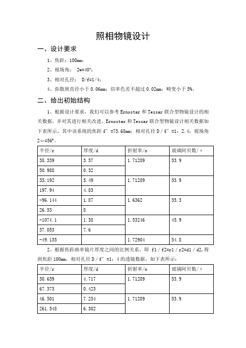
照相物镜设计一、设计要求1、焦距:100mm;2、视场角: 2w=40˚;3、相对孔径: D/f=1/4;4、弥散斑直径小于0.06mm;倍率色差不超过0.02mm;畸变小于5%。
二、给出初始结构1、根据设计要求,我们可以参考Ernostar和Tessar联合型物镜设计的相关数据,并对其进行相关改进。
Ernostar和Tessar联合型物镜设计相关数据如下表所示,其中该系统的焦距f’=75.68mm;相对孔径D/f’=1:2.4;视场角2ω=56 。
2、根据焦距曲率镜片厚度之间的比例关系,即f1/f2=r1/r2=d1/d2,得到焦距100mm,相对孔径D/f’=1:4的透镜数据,如下表所示:3、启动ZEMAX,将修改后表中的数据进行输入,步骤如下:(1)打开ZEMAX,在主选单system下,选择wavelengths,输入所要的波长,第一列输入0.486,单位为microns,第二、三列分别键入0.587、0.656。
在primary中点击选1,即用第一个波长为近轴波长。
(2)输入孔径大小,因为设计要求相对孔径为1:4,焦距为100mm得到孔径D=100/4=25mm。
在主选单system菜单中选择general data,在aper value 上输入25。
(3)输入视场角,根据设计要求,设置的视场分别为0,6,10,14,20。
(4)输入曲率,面之间厚度,玻璃材质。
本次设计中共有5组透镜,其中最后两组为双胶合透镜,故共有9个面,回到LDE可以看到三个surface,STO、OBJ、IMA,在STO前后插入几组数据,除IMA外共计9组surface,按照修改后的表中数据进行输入,如下图所示,最后根据参考实验图可以确定STO在第6面上。
(5)画出图形。
①点击layout画出2D图形如下:②点击spot diagram 画出的点阵图如下:由图得其弥散斑半径大小分别为26.012um、32.990um、44.238um、55.642um、58.511um,其中大部分弥散斑半径大小大于60微米,不符合要求,故需要改进。
【基础】光学仪器基础课程设计凯涅尔目镜设计

【关键字】基础电气工程学院课程设计说明书设计题目:凯涅尔目镜设计系别:工业自动化仪表年级专业:xx学号:xx学生姓名:xx指导教师:教师职称:副教授讲师电气工程学院《课程设计》任务书课程名称:光学仪器基础课程设计说明:1、此表一式三份,系、学生各一份,报送院教务科一份。
2、学生那份任务书要求装订到课程设计报告前面。
电气工程学院教务科电气工程学院课程设计评审意见表目录第一章摘要 (2)第二章设计要求、参数计算及优化 (3)第一节设计要求 (3)第二节参数计算 (4)第三节优化......................................................................................... (6)第三章课设总结 (10)参照文献 (11)第一章摘要为了克服冉登斯目镜不能校正垂轴色差的特点,将平凸的接目镜换成双胶合透镜,这就是凯涅尔目镜。
如图1-1.满足象散和慧差的两个条件是:(1-1)(1-2)在图1-1中,在目镜中必须>0,即要求光阑位于目镜的前方。
由以上公式可以看到,当减小时增大,相当于增大的目镜的出瞳距离,由于胶合透镜组有可能采取比单透镜小一些的值,因此凯涅尔目镜的相对出瞳距离/可以到达1/2。
同时由于可以校正垂轴色差,视场可以达到45o~50o。
第二章 设计要求,参数计算及优化第一节 设计要求设计一个6×望眼镜的目镜,目镜焦距=20,出瞳距离=8,2=45,=2。
考虑场镜对整个目镜的焦距的影响,取:=1.2=1.2 ×20=24根据出瞳距离的要求=10,对接眼的透镜组来说: 由此得到接眼镜在规划条件下==0.415根据前面提到的单个透镜组对无限远目标成像时象散和慧差同时为零的条件: 将代入以上公式,得到要求的值:为了校正垂轴色差,接眼透镜组的=0,如果要求目镜产生一定的垂轴色差。
以便和物镜补偿,可以取一个大于零或小于零的数值。
DMUNA

1)點選 2)結構樹增加一個View,如圖1 3)彈出DMU 2D Maker 工具列,如圖2 4)即可開始作註解盒繪圖 5)移動視角即離開
圖1
圖2
DMU 2D Maker 工具列使用說明
在這裡的繪圖,只有作註解使用所以沒有尺寸的設定 畫線:使用兩點畫線 操作方法: 1)點選 4)完成,如圖1 畫箭頭:操作方法與畫線相同,箭頭在第二點結束點位置。如圖2 畫矩形:操作方法與畫線相同,完成圖如圖3 徒手畫:使用方法與畫線一樣,按MB1,拖拉之路徑 產生,如圖4。 畫圓: 操作方法: 1)點選 2)按MB1不放,滑鼠位置為圓心 3)拖曳調整圓半徑 4)放開完成,如圖5 •移動標註線按MB1拖拉 圖5 圖4 圖3 圖2 2)按MB1不放第一點 3)拖拉至第二點放開 圖1
將組力圖炸開,OK,如圖4 7)點選 將此畫面拍起來 圖4 圖5
作為首頁圖片 8)點選 建立一個3D模型超連
結,VRML格式,可於瀏覽器觀看
9)點選 10)點選 11)點選
加入文字說明,如圖1 停止報表製作。 離開編輯
12)開啟所製作HTML檔案,如圖2 13)點選Link to VRML 直接可在瀏覽器觀看模型 14)點選Image1小圖示,可看到我們所 拍的畫面。 14)完成 圖1
文字:標註文字 1)點選 2)選擇基準點 3)彈出對話框如圖1 4)完成,如圖2 圖1
基準點
圖2
清除畫面 點選此icom則清除此視景所有標註。
3-1-2.管理註解視景(Managing Annotated Views)
將所有註解視景,一起顯示出來,以便我們選擇。選取後直接切換至我們所的選註解視景。 操作方法: 1)結構樹如圖1 2)點選 3)選擇視景如圖2 4)OK完成 圖1 圖2
阿特弈耳art40pro说明书

阿特弈耳art40pro说明书佳能相机阿特弈耳art40pro已经进了自动对焦时代。
一些档次较高的照相机对于普通的摄影爱好者来说,它的性能和使用方法相对于简单多了,这样,我们只要选好景,构好图,轻轻按一下快门就能完成比较高难度的拍摄工作了。
相机的位置:摄影时直立位,把相机拿到眼睛位置,沿水平方向摄影,亦称目高摄影。
这种方法被使用地最多,拍摄画面非常自然,观尝者无异样感。
另外由于水平角度摄影,建筑物无倾斜感、给人稳重的感觉。
站立位于腰的高度,沿水平方向摄影,称为腰平齐。
这是从上部看焦点面的双眼反光相机全盛时期,人们常用的摄影方法。
现在用弯腰或屈膝的方法也和腰平位有同样的意义。
这种高度对于拍摄小孩时是有用的,如果站立状况下,以成人的高度俯视摄影,那么小孩的头部被夸大,得到的是不正常画面。
采用腰平位摄影,小孩子们被正常的反映出来了。
它是指相机接近地面,尽可能的沿水平方向对准被摄影的摄影方法。
快门的正确使用:首先必须要注意一点的是,快门速度必须调到固定档位,不能象光圈那样用在两档之间。
佳能相机阿特弈耳art40pro,都是卷片和快门上弦同时进行的。
所以在卷片时,必须将扳手扳到底,才能按动快门。
卷片和快门上弦分离的照相机,要单独上紧快门,才能使之按动实现曝光。
在按动快门时,手臂肌肉应保持松弛状态,不能抖动。
在使用中心快门时,一定要先调好速度,后上紧快门,这一程序切不可颠倒。
拍摄过后,应将快门释放,并调至B档,以免快门机构长时间受力而受损。
光圈的正确调节:在拍摄过程中,我们调节光圈时,都要逐档拨动。
在调节停滞式光圈时,每听一声“咔”的声音,即表明是某档光圈的正确档位。
要注意大速反复转动光圈调节环,即使是非停滞光圈,也要轻扳轻转。
光圈在使用时,可以不必受档位的限制,也就是把光圈调到f/8与f/11之间也能使用。
- 1、下载文档前请自行甄别文档内容的完整性,平台不提供额外的编辑、内容补充、找答案等附加服务。
- 2、"仅部分预览"的文档,不可在线预览部分如存在完整性等问题,可反馈申请退款(可完整预览的文档不适用该条件!)。
- 3、如文档侵犯您的权益,请联系客服反馈,我们会尽快为您处理(人工客服工作时间:9:00-18:30)。
目录
1.课程设计的背景及意义 (2)
2.设计的基本原理 (3)
3.课程设计的基本过程 (5)
4.设计的结果 (8)
5.镜头的优化 (11)
6.总结和结论 (14)
7.参考文献 (15)
1.课程设计的背景及意义
随着光学产业的迅速发展,各类光学器件都在不同程度的改变和影响着我们的生活,基于ZEMAX的摄影镜头设计便是十分重要的一部分,任何一个光学系统不管应用于和处,其作用都是把目标发出的光透过我们所设计的镜头,最后成像,光学镜头的好坏直接影响着成像系统的成像质量,基于柯克三合系统的镜头结构,能够对光学镜头所有六种像差进行校正的结构最简单摄影镜头,故而为世界各光学公司仿制,加之三片三组式柯克结构镜头成本低廉故而产量巨大,广泛应用于各中低档相机镜头之中。
通过对光学镜头的设计也是我们对与镜头设计有关的各类参数有更深的了解。
我负责查找ERNOSTAR镜头的基本结构以及应用参数,ERNOSTAR在摄影史上是具有划时代意义的摄影头,它的最大光圈在标准相机上可以达到2.0,要知道在1927年Tessar的光圈也就只有设计到2.7。
ERNOSTAR是当时第一支可以在光线条件较差的情况下使用的镜头,也是第一个可以在很差的光线下不使用三脚架的镜头。
因此了解它的工作原理以及特性对于我今后的学习有着十分重大的意义。
图1 生产研发ERNOSTAR镜头的ERNEMANN公司
2.设计的基本原理
基于柯克三合系统的镜头结构,需要设计出5种镜头,包括典型cooke-triple结构镜头、ERNOSTAR结构镜头、Tessar结构镜头Heliar结构镜片、sonnar 结构镜头。
2.1照相物镜的光学特性
(1)焦距f'决定了所成像的大小,当物体处于有限距离像高
y'=(1-β)f'tan w,β是垂轴放大率。
物距L都比较大,所以f'=L'。
(2)相对孔径照相物镜的相对孔径决定其受衍射限制的最高分辨率和相面光
照度。
这里N=D/ f'/λ,
(3)视场角
照相物镜的视场角决定其在接收器上成清晰像的空间范围,按视场角的大小,照相物镜分为:小视场物镜,中视场物镜,广角物镜,超广角物镜。
他们是物镜的重要的特性参数。
另外在模拟仿真的过程中,还要注意所选取的镜头的曲率半径,厚度,玻璃等。
(4)光圈
光圈是一个用来控制光线透过镜头,进入机身内感光面的光量的装置,它通常是在镜头内。
表达光圈大小我们是用f值。
F=镜头的焦距/镜头的有效口径的直径。
光圈F数值越小光圈越大,进光量越多,画面比较亮;光圈F数值越大光圈越小,画面比较暗。
(5)孔径角
由相对孔径来确定 2u=D/f,为光圈倒数的一半。
2.2 照相物镜的基本类型
(1)柯克物镜(三片式物镜)
柯克物镜是薄透镜系统中能够校正全部七种初级相差的简单结构,它能适应的孔径是D/f=4.5,视场是2w=50度。
设计基柯克物镜由三篇透镜组成,考虑到校正垂轴像差,即慧差、畸变和倍率色差的需要,应该把镜头做成对称是的。
(2)天赛物镜和海利亚物镜
天赛物镜和海利亚物镜都是有柯克物镜改进而成的。
若把柯克物镜最后一片正透镜改为双胶合透镜组,轴外光线中以上光线的胶合面上有最大的入射角,可造成高级像散和轴外球差的减小,这就构成了天赛物镜,光学性能指标为D/f=1/3.5到1/2.8,2w=55度。
如果把柯克物镜中的正透镜全部改成胶合透镜组,就得到了海利亚物镜。
(3)松纳物镜
松纳物镜也可以认为是在柯克物镜的基础上发展起来的,它是大孔径和小视场的物镜,可以减轻负透镜的负担,高级像差较小了,相对孔径增大了,但是使得垂轴像差的校正发生了困难。
(4)ERNOSTAR物镜
ERNOSTAR结构是当时德累斯顿Ernemann公司(Zeiss Ikon前身之一)年仅23岁的天才光学设计师Ludwig Bertele,根据Ludwig Bertele的设计,他将Cooke-Triplet结构中的第一片凸透镜替换成了一组两片相接合的凸透镜,最大光圈在标准相机上可以达到2.0,要知道在1927年Tessar的光圈也就只有设计到2.7。
ERNOSTAR是当时第一支可以在光线条件较差的情况下使用的镜头,也是第一个可以在很差的光线下不使用三脚架的镜头。
3.课程设计基本过程
3.1 ERNOSTAR最初原理图
图2 ERNOSTAR最初原理图
(1)前三个镜片用于获得一个较长的焦距,之后通过与前三片透镜距离较远的
第三片透镜可以将这一焦距重新缩短。
这一结构在光线通过一个适中的孔径时可以很好的控制眩光与散射。
(2) 前三个透镜用于校正场曲和轴向色差,但是不能校正全部初级像差。
(3) 前两个透镜用于减小系统的高级像差。
增大了物镜的相对孔径,同时两
透镜使透镜表面半径增大,从而减小光线在表面的入射角。
3.2 ERNOSTAR参数
曲率半径r 厚度d 折射率
r1=83.561 d1=5 1.63812
r2=-126.94 d2=0.1
r3=24.604 d3=11 1.63842
r4=59.796 d4=3
r5=-118.5 d5=5 1.7398
r6=14.956 d6=10.73
r7=51.382 d7=7 1.63842
r8=-24.504
图3 通过查找资料,在镜头数据编辑页面输入物镜的初始参数
图4 输入光圈
图5 输入三种视场0deg,5deg,10deg
图6 输入三种波长的光蓝,绿,红
3.3 ERNOSTAR镜头设计基本过程
(1) 由使用要求提出对光学系统的合理要求,确定设计指标。
(2) 对光学原理图进行分析,对系统外形尺寸进行计算,可行性分析设计指标修正。
(3) 确定光学系统的初始结构,并求初始解。
(4) 对初始解进行像差校正(必要时修改初始结构)和像质评价得到光学系统结构参数。
(5) 进行光学系统公差设计和分析。
(6) 绘制光学系统图和零部件图。
(7) 完成设计报告。
图7 设计流程图4.设计的结果
图8 输出效果图
图9 像差图
最大像差为1000um 随着视场角不断增大,最大相差增大。
图10 光程差图
最大光程差为400 ,随着视场角增大最大光程差增大。
由于离焦影响,未能出现理想优化结果
图11 点列图
由图可见,色差很大,随着视场角的增大,彗差出现并越来越明显。
图12 调制传递函数图
图13 场曲图
由图可见,虽然有色差但不太明显。
像差为50。
5.镜头的优化
通过改变厚度,曲率参数来观察像差曲线,点列图的变化,从而得出结论。
所改的参数是否有利于镜头的优化。
图14 改变参数后的参数图
由参数表可知,加宽了第二块透镜与第三块透镜之间的距离。
图15 改变参数后的效果图
图16 改变参数后的像差图
由图可以看出,曲线变的平缓,各条曲线变得更加紧密。
图17 改变参数后的光程差图
由图可以看出优化后曲线更加平缓,由于离焦效应未能出现理想曲线。
图18 改变参数后的点列图图
由图可见,点列图比优化前排列更为紧密。
6.总结和结论
此次实验是基于ZMAX设计摄影头。
虽然目前所研究的镜头多为已研究成型的镜头,但是它们所含有的经典理论以及设计思想依然值得我们有所借鉴。
通过此次对ERNOSTAR镜头的学习,我对镜头的设计,原理,性能参数都有了一定的了解。
一个镜头性能好坏主要是基于是否可以有效的减小高级像差。
若要减小高级像差可以在正透镜中使用折射率更高的玻璃或用两个甚至更多的透镜代替原有结构中透镜。
通过查找资料发现,一系列的镜头都源自一个经典的镜头,它就是
Cooke-Triple镜头。
Cooke-Triple都是有是三片三组的结构,之后光学设计师们就一直在设法改进这个结构,著名的有Tessar,Heliar,ernostar等等。
1916年在美国芝加哥的Charles M. Minor尝试着将Cooke-Triplet结构的光圈设计的更大,他的做法是在Cooke-Triplet结构的第一片凸透镜和第二片凹透镜之间插入一片凸透镜,三篇镜片相连。
根据他的设计当时生产出了光圈为1.9的Ultrastigmat电影镜头,焦距分别为40, 50, 75mm,这几个电影镜头可以表现出一种很狭长的视角。
此次实验使我受益匪浅,在获得知识的同时感到自己的诸多不足。
我会继续努力学习奋斗,不断完善自己。
7.参考文献
《光学设计教程》黄一帆,李林编著北京理工大学出版社《光学设计》刘钧,高明编著西安电子科技大学出版社。