RN100用户手册
彩途N100,N200,n300,N400,N600使用说明书

4、使用配套的附件 请使用规定型号的电池,使用错误型号的电
池会对仪器造成伤害并可能发生爆炸;务必按照 说明处置用完的电池;只能使用配套的电缆和天 线,非配套的电缆和天线会严重降低性能并损坏 接收机,且无法得到保修。
5、许可协议 未经北京华辰北斗信息技术有限公司的书
面许可,任何人均不得以任何目的,任何方式复............................................... 30
3.5.1 地图页面 ....................................... 30
3.5.2 地图子菜单.................................... 30 3.5.3 查找分类 ....................................... 31
3.8 设置........................................................... 38
3.8.1 系统.............................................. 38
3.8.2 页面.............................................. 38 3.8.3 地图.............................................. 39 3.8.4 单位.............................................. 39 3.8.5 航向.............................................. 40 3.8.6 校准.............................................. 41 3.8.7 USB .............................................. 41 3.8.8 用户信息 ....................................... 41
N300用户手册增加
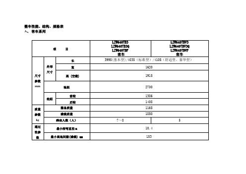
整车性能、结构、规格表A、客车系列倒车雷达(如装备)使用提示当变速杆挂入倒车档“R”时,此时系统进入自检状态:若两组传感器功能正常,则蜂鸣器发出“哔!”的一声。
若任一组传感器功能异常,则蜂鸣器发出“哔!哔!”的二声短音。
若两组传感器功能异常,则蜂鸣器发出“哔!哔!哔!”的三声短音。
正常状态下,在距离障碍物120cm 以上时,倒车蜂鸣器不应发出“哔!”的声音。
当你在倒车时听到“哔!”“哔!”“哔!”的长间歇警告音时,表示您车后传感器距离的障碍物已经进入120cm的范围内。
当你在倒车时听到“哔!”“哔!”“哔!”的短间歇警告音时,表示您车后传感器距离的障碍物已经进入90cm的范围内。
当你在倒车时听到“哔!”“哔!”“哔!”的急促间歇警告音时,表示您车后传感器距离的障碍物已经进入60cm 的范围内。
当你在倒车时听到“哔!”“哔!”“哔!”的长鸣警告音时,表示您车后传感器距离的障碍物已经进入40cm的范围内。
注:在长鸣区(0~40cm)内有障碍物时倒车,会导致测试距离不准确。
当障碍物进入40cm后,再退出60cm之前钥匙和遥控器( 如装备)钥匙有两把钥匙,用于点火和打开所有车门。
请将备用钥匙保存在汽车以外的安全地方, 以防车辆被盗。
遥控器( 如装备)您的汽车如果配备了遥控器,关于遥控器的使用请参见" 中控锁系统"。
请妥善保管您的遥控钥匙(两个)。
1. 遥控开(UNLOCK ): 。
2. 遥控关(LOCK ): 。
更换遥控器电池1. 用一把小十字起将遥控器表面的螺钉拧开,然后轻轻地将前体和后盖分开。
2. 小心将电池由遥控器中取出。
切勿用硬金属件将电池猛力撬出。
3. 更换电池。
4. 重装遥控器,确保前体和后盖结合紧密,以免进水。
5. 检查遥控器的操作。
OM2618中控锁系统( 如装备)中控锁是由驾驶员侧车门来控制的。
当驾驶员侧车门用钥匙或车门门锁钮来上锁或开锁时,所有车门都会同时被上锁或开锁。
AFN100使用说明书C1.1

进入查看界面,再按【3 】键,可查看 总线上探头 / 模块的运行状态指示,每页可以 显示 30 个点的状态信息,按上下键可下翻循环 查看,可以较直观地观察各地址的运行情况。 系统会对新接入的探头 / 模块及时登录,显示 界面动态刷新.
远程启停启停分机上的消防设备输入栋区层号设备代号第七章快速使用22afn100使用说明书专业安全诚信服务00离子探头22备用泵启44迅响器66排风机启01光电探头23备用泵停45试验阀67排风机停02感温探头24稳压泵启46消防栓灯68气体灭火启03烟复合头25稳压泵停47泡沫阀69气体灭火停04光复合头2670备用设备启05三复合头2749消防广播71备用设备停06激光探头28正压风机启50消防警铃72码座离子07一氧化碳29正压风机停51防火门73码座光电08可燃气体30排烟风机启52防火阀7409空气采样31排烟风机停53排烟阀75泡沫喷淋10手报按钮32干粉系统启54电梯76高倍泡沫11消防栓钮33干粉系统停55疏散指示7712压力开关34新风机启56事故照明78普通光电13水流指示35新风机停57非消防电79普通温感14信号阀36发电机5880气体报警15接口模块37消防泵故障59送风口81气体喷放16消防栓泵启38喷淋泵故障6082气体故障17消防栓泵停39稳压泵故障6183气体失重18喷淋泵启40水冷却6284高水位19喷淋泵停41泡沫喷淋63水冷却阀85低水位20泡沫泵启42送风机启64卷帘半降21泡沫泵停43送风机停65卷帘全降23afn100使用说明书专业安全诚信服务
注意:探头的火警总数和故障总数的 显示位数都为两位。
说明:每排显示 4 个地址,每屏显示 3 排 1 2 个地址。 2.2.4.4 事件查看
中国联通宽带使用指导手册(图文版)
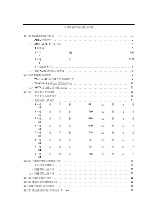
中国联通宽带使用指导手册第一章ADSL网络硬件设备 (2)一、ADSL硬件接法 (2)二、ADSL MoDE指示灯说明 (3)1中达通 (3)2、华勤64243、贝尔630753、诺基亚5110 (6)三、根据ADSL指示灯排障步骤 (6)第二章宽带连接图解步骤 (7)一、Windows XP系统建立宽带连接方法 (7)二、WINDOWS系统建立宽带连接方法 (17)三、VISTA系统建立宽带连接方法 (22)第三章常见无法上网问题 (30)一、无法上网处理步骤: (30)二、常见错误代码说明 (31)1、错误代码691处理方法312、错误代码769处理方法323、错误代码678处理方法334、错误代码619处理方法335、错误代码718处理方法336、错误代码734处理方法337、错误代码797处理方法348、错误代码735处理方法34第四章上网速度变慢问题解决手册 (34)一、上网速度变慢原因 (34)二、网速慢的检测方法 (35)三、网速慢的处理方法 (35)第五章上网经常掉线问题 (36)第六章播放电影常遇到的问题 (37)第七章建立连接正常但网页打不开 (38)第八章建立连接正常但无法收发E- mail (38)中国联通宽带使用指导手册尊敬的联通用户:在宽带使用过程中可能会出现一些故障导致无法上网,在报障碍 之前请您先仔细阅读下面常见的故障现象及解决方法, 看看对您是否 有帮助。
第一章ADSL 网络硬件设备一、ADSL 硬件接法正确的分离器与电话及 ADSL Mode 啲接法图示网钱 口个人计算机分离器的说明图分离器电话机I 歸 ADSL (Iel(I 电InADSL Moder与电脑连接示意图二、ADSL MODEM示灯说明1、中达通PWR正常供电时,电源灯亮。
LAN/ACT灯号亮起时表示10MbPS网络已连接。
LAN(RJ-45)为网线接口。
LN(DSL):灯号亮起表示PreStige已与在外局端之DSLAM联机,灯号熄灭表示在非联机状态。
NN100设计手册

10.64
550
9000
2.74
10.22
528
10000
3.05
9.77
505
1.11 1.07 1.04 1.00 0.96 0.93 0.89 0.86 0.82 0.78 0.75 0.72 0.69 0.66
5
(2)灭火剂量的计算 通过(1)计算出来的基本灭火剂量和灭火剂钢瓶组到被保护区的喷头之间的所有灭火剂充满的
×π
× L2
+⋅⋅⋅+
Dn2 4
×π
× Ln
Dn : 配管的内径(m) (n=1,2,3,・・・)
Ln : 配管的长度(m) (n=1,2,3,・・・)
(3.3.3)
作为参考,下表列出了 100m 长度的配管内的体积值(JIS 规格 sch80 配管)。
配管公称直径
20A 25A 32A 40A 50A
-1000
-0.30
15.23
787
0
0.00
14.70
760
1000
0.30
14.18
733
2000
0.61
13.64
705
3000
0.91
13.12
678
4000
1.22
12.58
650
5000
1.52
12.04
622
6000
1.83
11.53
596
7000
2.13
11.03
570
8000
2.45
QD
=Q ND
这里
QD : 1 个喷头的流量值(m3/min) Q : 流量(m3/min)
Navigator100 FM使用及技巧

4 移动测量—移动测试操作步骤
7) 检查GPS状态
测试前建议检查GPS状态。GPS必须锁定3颗以上卫星,能够正常更 新地理坐标和时间信息。 操作: 通用菜单->”GPS?” ,用滚轮查看GPS的各状态。
8) 开始测量
完成上述步骤后,即可开始测量。 操作: 通用菜单->”CGN MES ?”->”CGN START”,双击“Enter”键开始测量。
4 移动测量—GPS
• GPS测试 GPS测试是移动测量的必要条件之一。在移动测量开始之 前,需首先检查GPS的连接状态。只有当卫星数不少于3颗, 经纬度可正常读取后才适合开始进行移动测量。 • GPS状态菜单的进入 GPS状态菜单是通用菜单的子菜单。进入通用菜单后,通 过滚轮选择“GPS ?”,按“Enter”键进入。
4 移动测量—移动测试操作步骤
5) 记忆卡容量检查
测试前建议检查记忆卡的剩余空间大小。如空间不够,则应先将数 据导出再开始测试。 操作: 通用菜单->”CGN MES ?”->”CAPACITY”,自动显示已用空间大小。
6) 格式化记忆卡
记忆卡的总容量是8Mb。建议在每次数据导出之后格式化记忆卡。 操作: 通用菜单->”CGN MES ?”->”CGN ERASE”,双击“Enter”键开始格式 化。
单击保存
4 移动测量—移动测试数据导出
3 面板操作—频率存储菜单
无论在哪个菜单下,单击“Program”键即可进入频率存储菜单 当选中一个频道频率值为空“EMPTY”时,不能进入相应通用菜单 用转轮选择需修改频道->单击“Enter”键进入->用转轮修改频率->单击 “Enter”确定修改 频率范围从87.5MHz~108.0MHz,共可存储50个频道
TN-100 总氮分析仪中文操作手册 免费
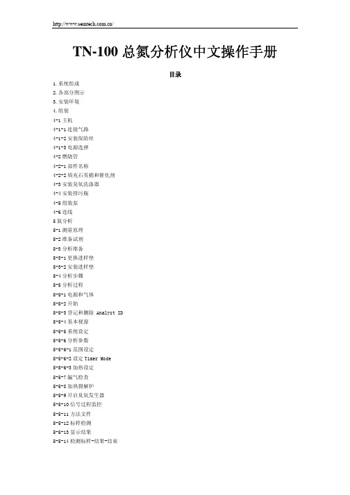
TN-100总氮分析仪中文操作手册目录1.系统组成2.各部分图示3.安装环境4.组装4-1主机4-1-1连接气路4-1-2安装保险丝4-1-3电源选择4-2燃烧管4-2-1部件名称4-2-2填充石英棉和催化剂4-3安装臭氧洗涤器4-4安装排污瓶4-5组装泵4-6连线5氮分析5-1测量原理5-2准备试剂5-3分析准备5-3-1更换进样垫5-3-2安装进样垫5-4分析步骤5-5分析过程5-5-1电源和气体5-5-2开始5-5-3登记和删除 Analyst ID5-5-4基本视窗5-5-5系统设定5-5-6分析参数5-5-6-1范围设定5-5-6-2设定Timer Mode5-5-6-3加热设定5-5-7漏气检查5-5-8加热裂解炉5-5-9开启臭氧发生器5-5-10信号过程监控5-5-11方法文件5-5-12标样检测5-5-13显示结果5-5-14检测标样-结果-结束5-5-15检测样品5-5-16结果和检测结束 5-5-17检测结束6其他相关操作6-1打印6-1-1设定打印机6-1-2打印报告6-2再计算6-2-1校准曲线再计算 6-2-2样品曲线再计算 6-3浏览结果7系统诊断7-1系统检查7-2漂移检查8维护8-1系统维护8-1-1日常维护8-1-2阶段性维护9故障判断与排除9-1常见问题9-1-1主机没电9-1-2炉温不上升9-1-3 Ready不显示9-1-4检测时间过长9-1-5测量数据偏差9-2错误信息10参数10-1参数10-2配件10-3配件图1. 系统组成: TN-100主机+CRI-100V恒速进样器+泵+电脑和打印机2.各部分图示TN-100主机前面1.电源开关2.电源灯3.臭氧开关4.臭氧指示灯5.加热器开关6.加热器指示灯7.氩气流量控制钮8.氧气流量控制钮9.预备灯主机后面1.电源插口2.保险丝3.地线4.加热器保险5.主电源开关6.泄漏指示灯7.泄漏检测8.输入电压选择9.泵连接口10.气体接口11.氧气接口12.排气口13.臭氧洗涤器14.臭氧流量控制15.风扇排气口16.电脑连接口17.附件接口18.记录器输出口19.ASI接口1.燃烧炉2.隔热垫3.加热管4.风扇主机上部1.进样口2.燃烧管珐琅3.样品珐琅4.氧气管5.氧气和氩气管泵1.电源2.洗涤器口3.管口4.油面视窗5.排油口6.温度保护7.电源线室温15-35℃,湿度80%避光,避震,避磁防火,防尘电源:220+10%,1。
海尔洗衣机用户手册说明书

12 1-25503A
SCREW TSEI
13 1-11533
HEX NUT
14 EAC0100G63A
PLASTIC COVER ASSY M2
15 1-22323A
SELF-TAPPING SCREW
16 1-9841
WASHER,PLAIN d6 ZINC.
17 1-9641
WASHER
Désignation
1
X
M12X35 8.8 A2J
1
X
SONAR VERSION
1
X
COBERT. INF. GRUPO MIS. TORNILLO AUTORR. Transformador 100/230V Transformador Transformador 230/230V Transformador 100/230V TAPÓN CASQUETE NEGRO TORNILLOS M5
1 EAA0263G07A
J-TYPE BRAKE PEDAL
1 EAA0372G98A
ALU BRAKE PEDAL 2 SWICTHES
2 EAC0060G00A
VIBRATORY SYSTEM HOLES CUP
3 EAC0060G02A
FLANGES PROTECTION
4 EAM0006G01A
LCBS-2-6-01 3
Entretoise
Distanciador
,M4X10 M/F 1
VIS CB RONDELLE
Tornillo ARANDELA
M4 x 6 1
UNI 7687
Ø 4,2 1
X
X
X
X
RNR全能型USB运动控制卡V1快速入门手册说明书
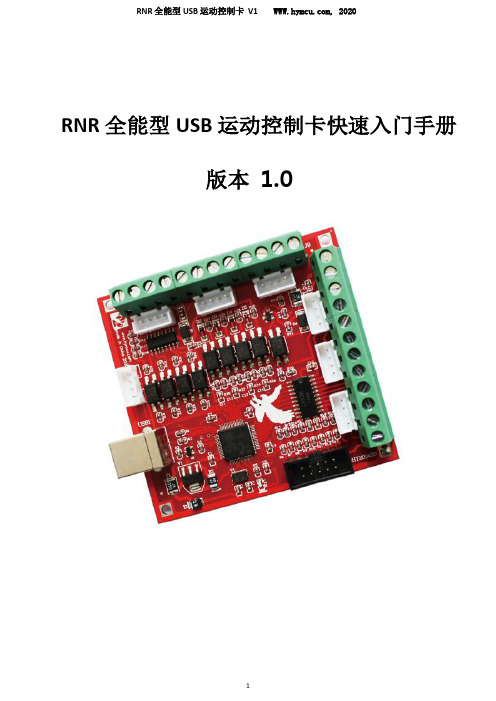
RNR 全能型USB 运动控制卡快速入门手册版本 1.0非常感谢您选购我司飞雕系列MACH3 运动控制卡!本文档将帮助初次接触使用本产品的用户快速完成产品的安装及调试。
准备工作首先,你要准备一台有 USB 接口的电脑。
飞雕系列 MACH3运动控制卡采用 USB 免驱动设计,所以兼容性好。
电脑的操作系统可以是 XP、WIN7、WIN8 系统。
可以是32 位系统,也可以是 64 位系统。
其次,你可能需要准备机床所使用的电机驱动模块的接线端子说明;如果有变频器,还需准备变频器接线端子说明。
42或者57系列电机驱动模块推荐选购我司 TB6600升级版驱动器或者DM542驱动模块。
对于需要连接急停开关、限位开关以及原点开关的用户,你需要准备这些开关和相应的接线端子说明。
急停开关一般采用蘑菇头开关。
限位开关和原点开关分为机械开关和电子开关(光电式、电感式、电磁式等形式)两种,机械开关比较简单,选购也没什么讲究。
选购电子开关时,应当选用 NPN 常开型。
这样比较容易接线。
Mach3 软件安装1、安装 Mach3 软件并运行 Mach3VersionR3.041 安装程序。
Mach3 安装很简单。
只要一直点击下一步(next ),或者是(Yes )即可。
如下图:下载资料中找到Mach3 软件,如图:选择 Mach3 安装位置,一般不需要改动,缺省安装在 C 盘的Mach3 文件夹中。
最后一步需要注意:对于 64 位的电脑,最好不要勾选 Load Mach3 Driver 这一项,因为这会引起系统提示安装错误。
点击“FINSH”。
Mach3 软件就安装完毕了。
2、破解及汉化接下来就是破解和汉化。
打开“mach3 汉化和破解.rar”压缩包。
如图:破解很简单,将压缩包中的文件 Mach1Lic.dat 拷贝到 Mach3 的安装文件夹中,覆盖原有的 Mach1Lic.dat 文件即可。
如果需要安装汉化包,就把“mach3 汉化和破解.rar”压缩包里面的文件全部拷贝至 Mach3 的安装文件夹中,覆盖原有文件。
RN100-482.505DN中文资料

RP100-S_DI Series
48V nom. 76.5V typ. 78.5V typ. 34V typ. 35V typ. 32V typ. 33V typ. L-C type 5V/ms max (Complies with ETS300 132 part4.4) 100VDC 25ms typ. 20mAp-p
Single Output
RP100-481.8S RP100-482.5S RP100-483.3S RP100-4805S RP100-4815S Part Number
Dual Output
RP100-483.305DI RP100-482.505DI
Load Input Efficiency Regulation Current(8) (9) V1 / V2 (mV) (A) % 25 / 16.5 25 / 12.5 16.5 / 12.5 2.39 2.45 2.44 87 85 85
INNOLINE
DC/DC-Converter
RP100S_DI Series
100 Watt Isolated Single & Dual Output
Selection Guide
Part Number Input Voltage (VDC) 36 – 75 36 – 75 36 – 75 36 – 75 36 – 75 Input Voltage (VDC) 36 – 75 36 – 75 Output Voltage (VDC) 1.8 2.5 3.3 5 15 Output Voltage V1 / V2 (VDC) 5 / 3.3 5 / 2.5 3.3 / 2.5 Output Current (A) 25 25 25 20 6.66 Output Current I1 / I2 (A) 20 / 25 20 / 25 25 / 25 Line Load Regulation Regulation (mV) (mV) 4 5 7 10 30 Line Regulation V1 / V2 (mV) 25 / 16.5 25 / 12.5 16.5 / 12.5 6 8 10 15 45 Input Efficiency (9) Current(8) (A) % 1157 1608 2022 2480 2507 86 87 90 90 90
N100R说明书
1序 言感谢您购买ipTIME N100R 无线宽带路由器! 产品简述:ipTIME N100R 无线宽带路由器集有线/无线网络连接于一体,专为满足小型企业和高端家庭用户的上网需要而设计。
符合IEEE 802.11n(Draft 2.0)标准,最高无线传输速率可达150M(1Tx-1Rx)。
采用MIMO 技术,提供更好的无线传输性能、稳定性和无线覆盖范围。
来自韩国的优秀设计,给你全新的使用体验。
ipTIME N100R 无线宽带路由器是专为满足小型企业、办公室和家庭办公室的无线上网需要而设计,它功能实用、性能优越、易于管理ipTIME N100R 无线宽带路由器基于IEEE 802.11n标准草案,它能扩展无线网络范围,提供最高达150Mbps的稳定传输,同时兼容 IEEE 802.11b 和 IEEE 802.11g标准。
传输速率的自适应性提高了ipTIME N100R 与其他网络设备进行互操作的能力。
大范围的无线覆盖空间为您提供了自由轻松的网络环境。
稳定的数据传输以及带宽供给为您的网上冲浪、MP3 下载、网络电话、文件共享、网络游戏等,网络服务提供了强大的技术保证,实现无忧上网。
ipTIME N100R 无线宽带路由器提供多重安全防护措施,可以有效保护用户的无线上网安全。
支持SSID广播控制,有效防止SSID广播泄密;支持 64/128位 WEP 无线数据加密,可以保证数据在无线网络传输中的安全。
内置的特有防火墙功能,可以有效防止入侵,为用户的无线上网提供更加稳固的安全防护。
ipTIME N100R 无线宽带路由器提供多方面的管理功能,可以对DHCP、DMZ主机、虚拟服务器等进行管理;能够组建内部局域网,允许多台计算机共享一条单独宽带线路和 ISP 账号;支持访问控制,可以有效控制内网用户的上网权限。
ipTIME N100R 无线宽带路由器安装和配置简单。
每步操作都配有详细的帮助说明。
特有的快速配置向导更能帮您轻松快速地实现网络连接。
Trimble Spectra Precision LL100N 用户指南说明书

User GuideBedienungsanleitung Manuel de l´utilisateurGuida per l´uso Gúia del usuarioGebruikershandleidingOperatörshandbok BetjeningsvejledningGuia do Usuário Bruksanvisning Käyttäjän opasРуководство пользователяTrimble Construction Division 5475 Kellenburger Road Dayton, Ohio 45424-1099U.S.A.+1-937-245-5600 Phone© 2008, Trimble Navigation Limited. All rights reserved. PN Q103740 (01/08)© 2008, Trimble Navigation Limited. All rights reserved PN 94038 Rev. C (11/13)Trimble - Spectra Precision Division 5475 Kellenburger Road Dayton, Ohio 45424 U.S.A.+1-937-245-5600 PhoneLL100N94038 Rev. C (11/13)13210operation.Thank you for choosing one of the Spectra Precision Lasers from the Trimble family of precision horizontal lasers.The LL100N is a simple-to-use laser that allows you to take accurate horizontal measurements, using a hand-held or rod mounted receiver.General Construction 7Determining the Height of Instrument (HI) 7Using the Y-Axis Single Slope Mode 7 CALIBRATION 8 Checking Calibration of the Y- and X-Axes 8 PROTECTING THE UNIT 8885.COMPONENTS1 Power Button2 Battery LED3 Manual/Standby Button (remote control)4 Leveling LED5 Manual/HI-Warning LED6 Up and Down Arrow Buttons (remote control)7 Left and Right arrow Buttons (remote control)8 Infrared-receiver for remote control9 Removable Rotor Cage10 Sighting Guides11 Rotor/Beam Exit12 Handle13 Battery compartment/door14 5/8x 11 Tripod Mounts15 Rubber feetHow to Use the Laser SystemPowering the LaserBatteriesInstalling BatteriesOpen the battery door using your fingers, a coin or a screwdriver.Insert batteries into the housing so that the negative poles are toward the bigger battery spiral spring.Push down on the battery door until the latch “clicks” into position.Laser SetupPosition the laser horizontally or vertically (tripod mount and rubber feet downward!) on a stable platform, wall mount or tripod at the desired elevation. The laser recognizes automatically whether it is used horizontally or vertically when switched on.Note: The laser always operates in MANUAL mode in the Vertical position.Turning On/Off the LaserPress the power button 1 to turn on the laser.Note: The laser always powers up in the automatic self-leveling mode. The LEDs (2, 4 and 5) are turned on for 2 seconds.The laser is level when the leveling indicator 4 is no longer flashing (once every second).For the first five minutes after the laser self levels, the LED 4 lights solid. After five minuts the LED 4 starts flashing every four seconds to let you know the laser is still level while conserving battery life.If the laser is positioned beyond it´s self-leveling range of ±8%, the laser beam, and manual and leveling indicators flash simultaneously. Turn the unit off, reposition the laser within the self-leveling range and turn it on again.Note: If the laser is out of its self-leveling range and remains out of it for more than 10 minutes, the unit shuts down completely.Note:After the laser has been level for more than 5 minutes in horizontal mode, the HI (height of instrument) alert activates. If the laser is disturbed (tripod bumped, etc.) so that when it re-levels the laser beam elevation changes by more than 3 mm (1/8 in.), the HI alert shuts down the laser and rotor, and the red LED flashes two times per second (twice the manual-mode rate). To restore level, turn the laser off and on. After the laser has re-leveled, check your initial reference elevation.In order to switch the laser off, press the power button again.Activating/Deactivating Standby ModeStandby mode is a power-saving feature that conserves laser battery life.Press and hold the remote control’s manual button for 3 seconds to activate standby mode.Note: When standby mode is activated, the laser beam, rotor, self-leveling system, and LEDs shut down, but the HI alert remains activated.6To let you know that the laser is in standby mode, the battery LED flashes every 4 seconds.To deactivate standby mode and restore full operation of the laser, press and hold the remote control’s manual button for 3 seconds.The laser and all other functions turn on again.Using the Manual ModeIn horizontal mode pressing the manual button on the remote control changes the laser from automatic self-leveling mode to Manual mode. Manual mode is indicated by the flashing (once every second) red LED 5.In Manual mode (horizontal), the Y-axis can be sloped by pressing the Up- and Down-Arrow-buttons on the remote control. Additionally, the X-axis can be sloped by pressing the Left- and Right-Arrow-buttons on the remote control. To resume automatic self-leveling mode, press the manual button again.In vertical mode, the laser is always in MANUAL mode. Pressing the up and down arrow buttons align the laser beam to the right/left side, and the left and right arrow buttons at the remote control adjust the slope of the laser beam.To resume automatic self-leveling mode, press the manual button again.Using the Y- Single Slope ModeThe Manual button on the remote control toggles the unit to Manual, the Y-axis Single Slope Mode, then Automatic Mode. To activate the Y-axis single slope mode, press the manual button at the remote control twice. This is indicated by the simultaneously flashing red 5 and green 4 LEDs (once every second).In Y-axis single slope mode, the Y-axis can be sloped by pressing the Up- and Down-Arrow-buttons on the remote control, while the X-axis remains in automatic self leveling mode (e.g. when setting up sloped ceilings or drive ways).To resume automatic self-leveling mode from Y-axis single slope mode, press the manual button again. APPLICATIONSGeneral ConstructionDetermining the Height of Instrument (HI)The height of instrument (HI) is the elevation of the laser’s Array beam.The HI is determined by adding the grade-rod reading to abenchmark or known elevation.1. Set up the laser and place the grade rod on a job-sitebenchmark (BM) or known elevation.2. Slide the receiver up/down the grade rod until it shows anon-grade reading.3. Add the grade-rod reading to the benchmark to determinethe height of instrument.Example:Benchmark = 30.55 m (100.23 ft)Rod reading = +1.32 m (+4.34 ft)Height of instrument = 31.87 m (104.57 ft)Use this HI as a reference for all other elevations.Using the Y-Axis Single Slope Mode1. Set up the laser over the reference point (A).2. Look over the rotor to align the laser to the desired direction hubin the axis that is supposed to be used in automatic self-leveling Array mode. Turn the laser on the tripod until it is properly aligned.3. Attach a receiver to a grade rod. Set the grade rod on the self-levelingaxis direction hub to check the laser’s elevation (B).Note: Use this HI as a reference for checking the alignmentof the laser after setting the slope for the other axis.4. Activate the Y-axis single slope mode by pressing the manual buttonat the remote control twice.5. Check the laser’s elevation on the slope axis directly in front of thelaser.76. Set the grade rod on the slope axis direction hub to adjust the laser’s elevation without changing the heightof the receiver on the grade rod (C).7. Press the up and down arrow buttons until you get an on-grade reading on the receiver.8. Recheck the laser’s elevation in automatic self-leveling axis using the HI in step 3 (B).If the HI has been changed, rotate the laser on the tripod until you get an on-grade reading again. Make sure, you DON’T change the height of the receiver on the grade rod.CALIBRATIONChecking Calibration of the Y- and X-Axes1. Set up the laser 30 m (100 ft) from a wall and allow it to level. Array2. Raise/lower the receiver until you get an on-grade reading for the+Y axis. Using the on-grade marking notch as a reference, make amark on the wall.Note: For increased precision, use the fine-sensitivity setting(1.5 mm/1/16 in.) on the receiver.3. Rotate the laser 180° (-Y axis toward the wall) and allow the laserto re-level.4. Raise/lower the receiver until you get an on-grade reading for the–Y axis. Using the on-grade marking notch as a reference, make amark on the wall.5. Measure the difference between the two marks. If they differ morethan 6 mm at 30 m (1/4 inch at 100 feet), the laser needs calibrating.6. After checking the Y-axis, rotate the laser 90°. Repeat the abovestarting with the + X axis facing the wall.Note: If calibration is required, please, refer to thecalibration instructions on our Trimble website/support.shtmlPROTECTING THE UNITDo not expose the unit to extreme temperatures or temperature changes (do not leave inside the car).The unit is very robust and can resist damage if dropped even from tripod height. Before continuing your work, always check the leveling accuracy. See Checking Calibration section.The laser is water protected and can be used indoors and outdoors.CLEANING AND MAINTENANCEDirt and water on the Rotor/Beam Exit (Component 11) will influence beam quality and operating range considerably.Remove dirt on the housing with a lint-free, warm, wet and smooth cloth. Do not use harsh cleansers or solvents.Allow the unit to air dry after cleaning it.89PROTECTING THE ENVIRONMENTThe unit, accessories and packaging ought to be recycled.This manual is made of non-chlorine recycling paper.All plastic parts are marked for recycling according to material type.Do not throw used batteries into the garbage, water or fire. Remove them in compliance with environmental requirements.Notice to Our European Union CustomersFor product recycling instructions and more information,please go to: /environment/summary.html Recycling in EuropeTo recycle Trimble WEEE, call: +31 497 53 2430, and ask for the “WEEE associate,” or mail a request for recycling instructions to:Trimble Europe BVc/o Menlo Worldwide Logistics Meerheide 455521 DZ Eersel, NL3 Year Limited WarrantyTrimble warrants the LL100N to be free of defects in material and workmanship for a period of three years. For the first 12 months, Trimble or its authorized service center will repair or replace, at its option, any defective part, or the entire product, for which notice has been given during the warranty period. For months 13 through 36 an exchange fee may apply. If required, travel and per diem expenses to and from the place where repairs are made will be charged to the customer at the prevailing rates. Customers should send the product to Trimble Navigation Ltd. or the nearest authorized service center for warranty repairs or exchange, freight prepaid. Any evidence of negligent, abnormal use, accident, or any attempt to repair the product by other than factory-authorized personnel using Trimble certified or recommended parts, automatically voids the warranty. The foregoing states the entire liability of Trimble regarding the purchase and use of its equipment. Trimble will not be held responsible for any consequential loss or damage of any kind. This warranty is in lieu of all other warranties, except as set forth above, including any implied warranty merchantability of fitness for a particular purpose, are hereby disclaimed. This warranty is in lieu of all other warranties, expressed or implied.TECHNICAL DATALeveling accuracy 1,3: ± 3 mm/30 m, 1/8“ @ 100 ft, 20 arc seconds Rotation:appr. 600 rpmOperational area 1,2: appr. 350 m (1150 feet) diameter with detector Laser type: red diode laser 650 nm Laser class:Class 2, <3mW Self-leveling range: appr. ± 5°Leveling time:appr. 30 sec Leveling indicators: LED flashes Laser beam diameter 1:appr. 5 mmOperating range using remote control: up to 30m (100 ft)Power supply: 2 x 1.5V Mono cells type D (LR20)Battery life 1:alkaline: 80 hours; NiMH: 35 hours Dust- and waterproof: IP54Operating temp.: 23°F...113°F (-5°C ... 45°C)Storage temp.:-4°F...158°F (-20°C ... 70°C)Tripod attachments: 5/8 x 11 horizontally and vertically Weight:1.5 kg (3.3 lbs)Low voltage indication: flashing/shining of the battery indicator Low voltage disconnection:unit shuts off1) at 21° Celsius2) under optimal atmospheric circumstances3) along the axisDECLARATION OF CONFORMITYWeTrimble Kaiserslautern GmbH declare under our sole responsibility that the product LL100N to which this declaration relates is in conformity with the following standards EN 61000-6-3:2007 + A1:2010, EN 61000-6-2:2005 and EN 60825-1:2007following the provisions of directive Electromagnetic compatibility 2004/108/EC.The managing directorElectro-Magnetic CompatibilityDeclaration of ConformityThis digital apparatus does not exceed the Class B Limits for radio noise for digital apparatus set out in the Radio Interference Regulations of the Canadian Department of Communications.This device complies with part 15 off the FCC rules. Operation is subject to the condition that this device does not cause harmful interference.Note: The product been tested and found to comply with the limits for a Class B digital device, pursuant to part 15 of the FCC rules. These limits are designed to provide reasonable protection against harmful interference in a residential installation. The product generates, uses and can radiate radio frequency energy and, if not installed and used in accordance with the instructions, may cause harmful interference to radio or television reception, which can be determined by turning the product off and on. The user is encouraged to try to eliminate the interference by one or more of the following measures:• Reorient or relocate the receiving antenna.• Increase the separation between the product and the receiver.• For more information, consult your dealer or an experienced radio/television technician.Caution: Changes or modifications to the product that are not expressly approved by Trimble could void authority to use the equipment.10。
RNS仪表国瑞华能手册正文

RNS200系列网络电力仪表1、 产品概述RNS200系列网络电力仪表是针对于对电力品质、电力安全有较高要求的场合以及有自动化需要的场合而设计。
它能测量所有的常用电力参数并且具备完善的通信联网功能,非常适合于实时电力监控系统。
该表作为一种先进的智能化、数字化的前端采集单元,因具有较高的性价比,目前已广泛应用于能源管理系统、变电站自动化、配网自动化系统、小区电力监控系统、工业自动化系统、智能建筑以及高低压配电盘、开关柜终端。
2、产品特点■ 可任意设定PT/CT 变比; ■ 全系标配RS485通讯/MODBUS 通讯协议; ■ LED 或高清晰LCD 显示,可视度高; ■ 全系可选蜂鸣器越限告警,具备声光提示; ■ 电能脉冲输出,4~20mA 模拟量输出 ■ 支持开关量输入,继电器输出 ■ 仪表采用专用失电保护电路,在失电情况下,数据保存不丢失,恢复电源后,仪表继续运行; ■ 面板嵌入安装,卡条固定;背插式端子接线设计,安装方便,接线简单;3、产品型号选配功能:J:继电器输出L:LCD液晶显示 AO:模拟量输出功能代码:详见型号一览表测量相数:1:单相3:三相仪表功能:9:多功能8:可编程成都国瑞华能电气有限公司网络电力仪表外形尺寸:48方形、48槽形、 72方形、96方形M:脉冲量输出 O:蜂鸣器告警4、产品功能选型配置表4.1 多功能网络电力仪表2、三相多功能仪表中,开关量输入和继电器输出各提供2路选配,若需增加至4路,则订货时需特殊备注。
24.2 RNS28系列可编程网络电力仪表说明:1、当选择48形多功能仪表时,功能输出项选配项继电器输出与模拟量(脉冲)输出只能任选其一。
2、72形和96形仪表的开关量输入和继电器输出各提供2路选配,若需增加至4路,则订货时需特殊备注。
5、RNS 200系列网络电力仪表性能指标技术参数 技术指标精度等级 电流、电压0.2级;功率、电能0.5级;频率:±0.05HZ输 入适用网络 单相、三相三线制、三相四线制 电压额定值 AC100V、AC220V(订货请说明)过 载 持续1.2倍,瞬间2倍/1秒电流额定值 AC5A或AC1A(订货请说明)过 载 持续1.2倍,瞬间电流10倍/1秒 频率 45Hz ~ 55Hz输 出通讯 RS485-Modbus协议开关量输入 AC220V/DC220V/DC110V ± 25%输入继电器输出 触点容量250VAC、5A,220VDC、0.5A,110VDC、1A,30VDC、5A 显示方式 可编程、切换;LED/LCD显示工作电源 宽 压 型 AC85V ~ AC265V, DC100V ~ DC300V 功 耗 小于3VA绝缘强度 2kV(各回路之间,测试电压为交流有效值) 绝缘电阻 ≥ 50MΩ工作条件环境温度:-20℃~+70℃ 储存温度:-30℃~+85℃ 相对湿度: 5%~95%,无凝露6、外形及安装尺寸48槽形96方形4RNS100系列智能数显仪表1、产品概述RNS100系列数显仪表采用交流采样技术,适用于高、低压配电系统的单、三相电流、电压、频率、功率及功率因数和电能等参数的测量与显示;该系列仪表可在线设置变比,并提供开关量输入、继电器输出及RS-485通讯等选配功能。
RM100电子说明书

或
(XX是普通用户编号,取值10到19之间;xxxxxxxxxxx是11位手机号码)到控制器手机号,可以实现给普通用户授权或修改普通用户。
7.1.3查询开关状态
B.1秒后,自动转入测量电流显示界面,如下图
此时表明已进入工作状态,若此时有电流,则显示测量电流一次值。
C.通过操作小面板上的上下按键,可以进行中文液晶显示屏的页面操作,所有液晶操作菜单导航图,如图四所示
D.参数值修改
如现在要修改过流电流值,如下图
在当前页面按下确定键,进入系统密码页,此时光标开始闪烁,如下图
3.9实时时钟功能
查看当前时间并提供修改,在线路发生故障时,能准确记录下故障发生时间。
3.10事件记录功能
可记录最近的256条详细记录事件,并提供本机随时逐条查询(第257条记录覆盖第一条记录,依次类推)。各种设定的数据自动进入记忆单元,10年不丢失。
3.11遥信量检测功能
可检测开关的当前状态,分、合闸位置。
4
4.1本地遥控器合、分闸和复位操作
利用遥控器可在本地进行遥控合、分闸。
合闸:先按“B”键,再按“D”键;
分闸:先按“A”键,再按“D”键;
复位:先按“C”键,再按“D”键;
备注:两次按键时间间隔不能超过3秒钟,否则前一次按键无效。
注意:如果遥控器长期不用,要把遥控器中的电池取出,并且经常检查遥控器电池是否充足(遥控器电池型号为:12VGP23A),若电量不足需及时更换。
键:返回键。取消值修改并返回到修改前的页面或测量页面。
键:复位键。回到解锁状态页面
注意:1.本控制器初始密码为“6666”.
2.每个按键都点亮背光灯,10秒内若无按键,则自动关闭背光灯。
MultiConnectrCell 100Series 路由器 LTE Cat4 产品说明书

MultiConnect ®rCell 100Series Router LTE Cat 4MTR-LNA7Quick StartMultiConnect ®rCell 100Series Router LTE Cat 4MultiTech Systems MultiConnect ®rCell 100Series Router LTE Cat 4MultiTech Systems MultiConnect ®rCell 100Series Router LTE Cat 4MultiTech SystemsQuick StartQuick StartQuick StartRight Side Panel for LNA7Side PanelsThe device has connectors on both sides of the housing.The right side of the device contains a reset button,Wi-Fi,GPS and Cellular connectors.Depending on the model,the GPS and the WiFi connectors may or may not be present.The left side of the device includes an RS-232connector,an Ethernet connector,and the power receptacle.Installing the Device1.To use the device's cellular features,connect the suitable antenna to the CELL connector and the AUX connector.2.Using an Ethernet cable,connect one end of the cable to the E-NET connector on the back of the device and the other end to your computer,either directly or through a switch or hub.3.If you are connecting to a serial interface,connect the DE-9connector (9-pin)of the RS-232cable to the RS-232connector on the device.Then connect the other end to the serial port on the desired device.4.Some devices support the use of a GPS receiver (varies with model).If you are using a GPS receiver with thedevice,attach the GPS cable to the GPS connector on the device.5.Some models support the use of WiFi or Bluetooth.If you are using WiFi or Bluetooth with the device,attach the WiFi/Bluetooth antenna to the WIFI connector on the device.6.Screw on the power lead from the power supply module into the power connection on the device.Plug the power supply into your power source.■The POWER LED lights after the device powersup.■When the STATUS LED begins to blink,thedevice is ready for use.7.You can configure your device by using your device’s web management interface.You might need to change the IP address of your computer to be in the same IP and subnet mask range as the device.a.Open a web browser.In the browser's address field,type the default address for the device:http://192.168.2.1.(If the browser displays a message about a problem with the security certificate,ignore and click Continue ).b.When logging in for the first time,the device enters commissioning mode requiring a username andpassword for an admin user account.Enter and submit your desired username and password.Confirm the password.c.Refer to the appropriate software guide for further details on first-time setup.Mounting the Device1.Locate the groove on the bottom of the modem.2.Slide the mounting tab through the groove.3.To secure the tab to the desired surface,place and tighten two screws in the holes on either end of the mounting tab.Refer to the user guide for an illustration of the mounting tab,as well as the dimensions for placement of the screws.MultiConnect ®rCell 100Series Router LTE Cat 4Part Number:82104500LCopyright and TrademarksThis publication may not be reproduced,in whole or in part,without the specific and express prior written permission signed by an executive officer of Multi-Tech Systems,Inc.All rights reserved.Copyright ©2019by Multi-Tech Systems,Inc.Multi-Tech Systems,Inc.makes no representations or warranties,whether express,implied or by estoppels,with respect to the content,information,material and recommendations herein and specifically disclaims any implied warranties of merchantability,fitness for any particular purpose and non-infringement.Multi-Tech Systems,Inc.reserves the right to revise this publication without obligation to notify any person or organization of such revisions or changes.MultiConnect,MultiTech and the MultiTech logo are registeredtrademarks of Multi-Tech Systems,Inc.All other brand and product names are trademarks or registered trademarks of their respective companies.MultiConnect ®rCell 100Series Router LTE Cat 4MultiTech Systems MultiConnect ®rCell 100Series Router LTE Cat 4MultiTech Systems MultiConnect ®rCell 100Series Router LTE Cat 4MultiTech Systems MultiConnect ®rCell 100Series Router LTE Cat 4MultiTech SystemsQuick Start Quick StartQuick StartQuick StartOverviewThe MultiConnect ®rCell 100Series Router LTE Cat 4provides secure data communication between many types of devices that use legacy and the latest communication technologies.Package ContentsYour MultiConnect ®rCell 100Series Router LTE Cat 4typically includes the following (varies with model):Power Supply 1-9VDC power supply with removable blades,1-NAM blade/plug.Cables 1-Ethernet cable with RJ-45connector,1-Power cable from power supplyAntennas2-CELL,AUX LTE external antennas,1-Wi-Fi/Bluetooth antenna (B10models),1-GPS antenna (B10models)Documents 1-Quick Start Guide,1-Warranty Plans,1-Activation,Support &Regulatory Information Other Items 1-Mounting tab,4-Clear adhesive bumpons or mounting feetDevice1-MultiConnect ®rCell 100Series Router LTE Cat 44.169"x 3.00"x 1.163"Blue enclosure includes:■7-32VDC power connector■RS-232(DE 9-pin,female-D)connector ■E-NET RJ-45receptacle for standard Ethernet 10/100Base-T■WIFI Wi-Fi/Bluetooth SMA connector ■GPS GPS female SMA connector ■CELL Cellular female SMA connector ■AUX Cellular female SMA connector47CFR Part 15Regulation Class B DevicesThis equipment has been tested and found to comply with the limits for a Class B digital device,pursuant to part 15of the FCC Rules.These limits are designed to provide reasonable protection against harmfulinterference in a residential installation.This equipment generates,uses,and can radiate radio frequency energy and,if not installed and used in accordance with the instructions,may cause harmful interference to radio communications.However,there is no guarantee that interference will not occur in a particular installation.If this equipment does cause harmful interference to radio or television reception,which can be determined by turning the equipment off and on,the user is encouraged to try to correct the interference by one or more of the following measures:■Reorient or relocate the receiving antenna.■Increase the separation between the equipment and receiver.■Connect the equipment into an outlet on a circuit different from that to which the receiver is connected.■Consult the dealer or an experienced radio/TV technician for help.Warning:Changes or modifications to this unit not expressly approved by the party responsible for compliance could void the user’s authority to operate the equipment.Additional InformationFor the latest information on your device including operation,regulatory,and safety topics,refer to the appropriate user guide online:/brands/multiconnect-rcell-100-seriesLED DescriptionsThe top panel contains the following LEDs:■Power and Status LEDs -The Power LED indicates that DC power is present and the Status LED blinks when the unit is functioning normally.■Modem LEDs -Two modem LEDs indicate carrier detectionand link status.■Signal LEDs -Three signal LEDs display the signal strengthlevel of the wireless connection.■Ethernet LEDs -These LEDs are not on the top panel.Thetwo Ethernet LEDs are physically on the RJ-45connector.■Ethernet Link LED -Located on the right on the Ethernetconnector.This LED blinks when there is transmit andreceive activity and is steady when there is a valid Ethernet connection.■Ethernet Speed LED -Located on the left on the Ethernetconnector.When lit the Ethernet is linked at 100Mbps.If it is not lit,the Ethernet is linked at 10Mbps.Installing a SIM CardIf you want to operate the device on a particular network,install a micro (3FF)SIM card.MultiTech recommends using a SIM card rated for industrial use.To install the SIM:1.Locate the SIM card slot on the side of the device.The slot is labeled SIM.2.Push the SIM card into the slot until it snaps into place.。
RNS系列三相智能数字仪表V2.0
RNS系列三相智能数字仪表用户手册V2.0成都国瑞华能电气有限公司非常感谢您选择由本公司开发生产的数显智能仪表电力仪表,为了您的安全、正确和高效地使用本仪表,请仔细阅读本手册并在使用时务必注意以下几点:仪表只能由专业人士进行安装和维护。
仪表在使用时请提供正确的额定输入电压和电源。
对仪表进行安装与维护前,应断开输入电压和电源,并将电流互感器的二次绕组短接。
要用电压检测设备来确认电压已断开。
提供该仪表的电参数需在额定的范围内。
在将仪表通电前,应将所有的机械部件、端子恢复原位。
仪表存储与使用时请遵守本使用手册中规定的环境条件。
对于因不遵守本手册的说明而引起的故障,厂家将不承担任何责任。
本手册适用于三相数码管显示智能仪表,手册中产品外观(指示灯、丝印)等仅用于功能介绍,请以实际产品为准。
当仪表带电时,请勿接触端子!不注意这些预防措施可能会引起严重伤害!目 录一、概述 (1)二、外形及开孔图 (2)三、仪表型号及功能配置 (3)四、技术参数 (6)五、典型二次接线图 (7)六、端子示意图 (9)七、数码管型仪表设置说明 (10)八、附注说明 (15)一、概述RNS系列三相数字仪表,广泛应用于高、低压智能配电系统,其中低压仪表适用于220/380V系统;高压表适用于3kV及以上系统。
产品具有电压、电流、有功功率、无功功率、功率因数、有功电度、无功电度、频率、视在功率等测量功能;亦具有开关量输入、继电器输出和蜂鸣器告警辅助功能,还可通过RS485/Modbus通讯方式,对仪表进行组网管理。
用户还可通过控制面板上的按键进行在线编程,根据工程需求在线设定参数,真正实现智能化。
本手册同时适用于RNS153,RNS163,RNS183,RNS283,RNS293等五大系列的三相数码管和液晶仪表。
产品生产环节严格依据ISO9001质量管理体系,产品技术标准参照GB/T22264-2008.二、外形尺寸及开孔图72方形外形图72方形开孔图、三相仪表型号说明及功能配置RNS □ □ 3 □— □ □① ② ③ ④ ⑤ ⑥ ⑦①:国瑞华能仪表注册型号;②:产品系列:1‐数显仪表 2‐网络电力仪表;③:仪表类型;5‐电测型 6‐可编程型;8‐智能型④:相数:三相仪表⑤:缺省‐数码管 L‐液晶;⑥:测量参数(详见后续说明);⑦:辅助功能(详见后续说明)。
Remotesat RST100 智能卫星通信终端说明书

RemoteSAT RST100The Beam RST100 is a single-channel intelligent voice and data communication terminal. For use inside a building, motor home, boat, vessel or a fixed site location providing easy satellite communication, utilizing the latest Iridium satellite transceiver, the 9522B.Voice communications are accessible via the intelligent RJ11/POTS (Plain Old Telephone System) port for using up to 3 standard cordless or corded telephone handsets or for integrating with a PBX system enabling easy access from any handset connected to the PBX.The optional compact Intelligent Handset with hang up cradle, SMS and phone book features can be used for voice calls. This handset is commonly used in conjunction with standard phone equipment.The RST100 has an intelligent processor on board for managing an advanced RJ11 port, supporting abbreviated dialling, auto-dial, speed dial, call barring, call logging as well as configurable dial, ring and busy tones that can be set to country specific tones.Internet, Fax and all the Iridium Data services are supported via the data port on the RST100 RemoteSAT terminal. Captain & Crew CallingConnection to PBX System In-building satellite communications Emergency Services RJ11/POTS ConnectivityVoice/Data/FAX/SMSLocal & Remote ConfigurationVoice/DATA/FAX/SMSThe complete range of Iridium data services allows you to simply and conveniently gain access to Internet, Email, and corporate LAN. Intelligent Proccessor & Interface The Intelligent processor enables the terminal to be configured remotely or locally. Locally it can be configured witha PC using the Beam ManagementSystem (BMS) software supplied with theTrackALERT terminal.It is also possible to configure and checkstatus of the unit remotely by sendingcommands to the terminal using SMS.External Ringer/Alert The RST952 ringer/call alert connectssimply to the RJ11 port of the terminaland provides an amplified alert with volume,pitch controls as well as an on/off button.Supports Back up Battery The use of an RST050 Beam Battery Back-up is an ideal accessory where guaranteed communication is required, providing 24-hours standby/2-hours talk time.Fully Approved The RST100 is a fully approved product by Iridium Communications Inc.Fully Certified Corrosion / vibration / RoHSC, CE, FCC, IEC160945Power Input The RST100 support an 11-32V DC power input. AC/DC power cable is supplied along with an AC 110/240 plug-pack (requires country specific monitor cable) which makes it easy to connect tomains or DC power.RJ11 / POTS ConnectivityThe RJ11/POTS interface emulatesPSTN (Public Telephone Service) featuresand is equipped with off-hook detection,configurable Ring, Busy & Dial service tones. 9522B Iridium SatelliteTransceiverThe RST100 uses the lastest Iridium9522B transceiver inside the terminal toacccess the satellite network.Support Intelligent Compact handset The RST100 supports an optional Intelligent Handset for voice calls as well as utilizingthe Iridium SMS service. The handset iscompact and provides easy access tonetwork status, phonebook and SMS.Supports Standard Phones Voice services can be easily accessedanywhere on earth using a standardtelephone handsets. This means voicecommunications can be easily accessedusing standard Corded, Cordless, DECTor PBX systems. Connect to PABXUse of the intelligent RJ11 interfaceenables the easy integration with aPBX system allowing for multiple useraccess to satellite calls from any handsetconnected to a PBX.Phone Number ProcessingThe intelligent number processing is idealfor various applications. Call barring andrestricted dialling within certain countriesor area codes can also be configured ifrequired. Abbreviated & Speed Dialling isalso supported on the terminal.Handsfree (Optional)RJ11/POTS Voice DataTrackingPOWER SPECIFICATIONSPower input voltage 11 - 32 V DCPower Consumption ( AMPS )12 V DC 24 V DC Stand-by 0.350.16Transmit 0.510.25Stand-by - inc handset 0.470.22Transmit - inc handset 0.590.29ENVIRONMENT SPECIFICATIONSTemperature Degrees °C Degrees °F Operating Range -15 to +55+5 to +131Storage -30 to +70-22 to 158Humidity 93% non condensing Vibration 2 Hz - 13.2 Hz & 13.2 Hx - 100 hz Corrosion 40 °C with 90% - 95% relative humidity after 2h salt spray CONNECTORS/INTERFACESIntelligent Handset RJ45 DPL BUSTelephone / POTS RJ-11 2 -wire / TN12 or 600?Data Port RS232 Serial Interface Log Port RS232 Serial Interface Power 2 Pin screw type LED/DISPLAYPower GreenSignal 3 ColourCall YellowVoicemailGreen PHYSICAL SPECIFICATIONS UNIT ONLY PACKED Dimensions - mm 225 x 277 x 53400 x 325 x 90Dimensions - inches 8.8 x 10.6 x 1.215.7 x 12.8 x 3.5Weight - kg 2.25 3.25Weight - lbs 4.97.1CERTIFICATIONS IEC60945Germanischer Lloyd American bureau of Shipping Electrical Safety EMC Compliance C tick CE Compliance KIT CONTENTS RST100 Main terminal Mounting Brackets AC 110/240V Plug Pack DC 1.5m Power Cable Data Cable User & Installation Manual RST970RST030RST050RST973RST932RST933RST702RST705RST710RST715RST720Intelligent Iridium handset TrackALERT Terminal (In-built GPS)Battery back-up - 24 hours standby In-vehicle handsfree kit 6m Iridium antenna cable 12m Iridium antenna cable Iridium/GPS dual mode mast antenna Iridium/GPS dual mode magnetic mount antenna (incl. 6m cable for GPS & Iridium)Mast antenna Magnetic mount antenna (incl. 5m cable)Bolt mount antenna (incl. 5m cable)。
- 1、下载文档前请自行甄别文档内容的完整性,平台不提供额外的编辑、内容补充、找答案等附加服务。
- 2、"仅部分预览"的文档,不可在线预览部分如存在完整性等问题,可反馈申请退款(可完整预览的文档不适用该条件!)。
- 3、如文档侵犯您的权益,请联系客服反馈,我们会尽快为您处理(人工客服工作时间:9:00-18:30)。
历史版本概述 (1)1.1产品简介 (1)1.2主要特点 (1)1.3主要技术指标 (1)准备工作 (3)2.1机箱外形 (3)2.2传感器的连接 (3)基础操作 (5)3.1菜单操作 (5)3.2说明(Instruction) (5)3.3联系方式(ContactUs) (5)3.4电池电量显示(Battery) (5)3.5时间设置(TimeSet) (5)3.6显示屏设置(OledSet) (6)3.7恢复出厂设置(Format) (6)温湿度测量 (7)4.1通道类型设置(ChannelSet) (7)4.2相关参数设置(CoeffSet) (8)4.3存储方式设置(StoreSet) (8)4.4测量操作(TMeasure) (8)数据传输 (10)5.1串口连接 (10)5.2软件使用 (10)附录 (11)1.1产品简介RN-100型温湿场巡检仪是由济南荣诺电子技术有限公司出品的高精度仪器。
仪器能够同时测量20个通道,可以使用8种标准热电偶、Pt100热电阻以及其他传感器。
仪器体积小、重量轻、十分便携,并且有内置充电电池以及大容量存储器,真正做到使用方便,携带简单。
1.2主要特点★轻巧便携:尺寸255×205×95mm★可充电电源,随时随地使用摆脱电源线束缚★省电高亮自发光OLED显示★菜单式按键操作适于工业环境★数据可记录并可通过RS232与PC通讯★专业的热电偶冷端处理,冷端自动补偿★内置关机仍运行的实时钟★工作时可充电1.3主要技术指标外接电源:DC5V@2A电池连续工作时间>35小时16路温度通道支持8种标准热电偶(带冷端自动补偿)和Pt1004路湿度(通用)通道,带5V传感器电源,用户可设定标度变换各通道可独立关闭或打开记录开始时间及间隔可设定,间隔时间为(1~65535)秒记录存储方式可选存满覆盖或存满停止可存储1019条记录灵活的校准方式:通道可校准物理量、独立校准工程量、以指定通道为参考校准工程量电偶测量通道最大允许误差:±(0.2℃+0.02%×读数)(廉金属);1±(0.3℃+0.05%×读数)(贵金属)湿度测量通道最大允许误差:±(0.01%×量程)注意:实际测量的精度与所配传感器有关;传感器电源电压和输入类型可为用户定制;存储容量可为用户定制。
http:/2准备工作2.1机箱外形图2.1仪器面板简图左侧从上到下依次为:RS232串行接口,用于与电脑等设备进行通讯。
详情请参见第五章数据传输。
DC-IN 5V,用于接外部充电器/电源。
ON/OFF按钮,仪器开关,按下后,按钮开关灯亮表示仪器通电开机。
DC-IN指示灯,灯亮表示外部电源已经连接。
CHG指示灯,灯亮表示内部充电电池正在充电。
RUN指示灯,灯亮表示仪器正常工作。
四个基本按键:“MENU”、“→”、“↑”、“↓”。
2.2传感器的连接图2.2传感器的连接(见面板)31~20通道分别对应20组接线端子,每个接线端子对应四个接线口。
其中17~20通道对应的低接线口为供电端子。
1~16通道的接线口适用于8种热电偶、PT100、电阻或其他传感器。
热电偶只使用高接线口,正端接1V+,负端接1V-。
PT100需要接四线。
17~20通道主要用于湿度测量。
所有的通道都可以用作电压测量和自定义测量。
http:/4基础操作3.1菜单操作菜单分两级菜单以及若干功能菜单:主菜单(MainMenu)、子菜单(测量菜单(Measure)、设置菜单(Setting))和相应功能菜单。
菜单的按键操作是统一的,“↑”、“↓”键用来控制菜单选择箭头的上下移动。
“MENU”键按下会进入相应的子菜单或功能菜单。
“→”键作为菜单返回键,在子菜单下按下“→”键会回到主菜单。
功能菜单,是各种功能的设置及实现界面。
除测量功能菜单(TMeasure)外,所有功能菜单中的按键功能一致(测量功能菜单的按键功能详见3.4节测量操作),“MENU”键用于所有功能菜单的退出,“↑”、“↓”用于对数据的修改,“→”用于切换需要操作的数据。
注意:在菜单中的按键功能与功能菜单中的按键功能不相同!3.2说明(Instruction)仪器使用的简单说明。
3.3联系方式(ContactUs)相应联系方式,在仪器使用过程中出现疑问或故障,可以根据屏幕显示的联系方式联系我们。
3.4电池电量显示(Battery)显示充电电池的电量(电压值)。
电池为标准3.7V充电锂电池。
由于电池型号以及损耗等原因,电量显示会出现偏差,请根据测量值,并参照实际使用情况确定电池电量。
3.5时间设置(TimeSet)用于设置仪器运行时间。
进入菜单后,屏幕显示的时间为初始进入该菜单的时间。
进行修改后按“MENU”键退出,会重新设置仪器时间。
日期可以设置为2000-01-01至2099-12-31,时间格式是为24小时格式。
注:如没有修改时间,退回上级菜单,此操作不修改设备时间。
53.6显示屏设置(OledSet)用于显示屏相应的设置。
显示亮度04,显示关闭时间(30 S)为默认值。
显示亮度可以设置为02~15,超过15的设置值亮度实际值为15,建议亮度为04,如果在强光下,请注意遮光或设置更高亮度。
无操作时,显示屏会根据显示关闭时间的设置,间隔一段时间后自动关闭显示屏显示,按键可以唤醒显示。
显示关闭时间可以设置为0~99,单位为秒(S),其中0表示不关闭显示。
注:显示屏的设置会影响仪器电池的使用时间。
3.7恢复出厂设置(Format)用于恢复出厂设置。
如果仪器由于参数设置错误或其他原因不能正常工作,可以在此功能菜单下进行恢复出厂设置。
当选中状态为“YES”,按下“MENU”键确认,会出现确认码,将确认码修改为123,再次按下“MENU”键会格式化数据,并重新启动仪器。
选择“NO”,或者确认码错误,都不会进行任何修改,并且退出该界面,回到上级菜单。
注:请确认是否需要恢复出厂设置,该操作会将所有设定参数恢复出厂默认值,如果有重要参数,请自行记录,以备重新设定。
6温湿度测量4.1通道类型设置(ChannelSet)该功能菜单用于设置各通道的测试类型。
第一页编号(A至P)表示第1至第16通道,该通道组主要用于热电偶、热电阻测量。
每个通道都可以设置13种测量方式(测量类型详见表4.11)。
表4.11第二行编号(0、1、2、3)表示17至20通道,该通道组主要用于通用测量,每个通道都可以设置为3种测量方式(测量类型详见表4.12)。
表4.12注意:测量范围是仪器的理论测量值,实际值还取决于传感器的测量范围。
74.2相关参数设置(CoeffSet)该功能菜单用于设置仪器工作时使用的参数。
四套参数设置,每套参数都有两个参数K与B,参数为7位有效数字的科学计数法的数字。
每套参数的应用范围见表4.21,其中B的默认值均为0。
表4.214.3存储方式设置(StoreSet)用于设置数据存储方式以及定时自动测量功能。
数据存储开关,当置为“YES”,会将存储开关打开,如果数据没用存满,将自动记录测量数据。
存储覆盖标志,当置为“YES”,在存储满的情况下,会自动覆盖最早的测量数据。
B Use标志,置为“YES”,将启用修正系数B,详细功能参见4.4节测量操作。
数据存储周期,存储一次数据的时间间隔,可设3~65536 S(秒)。
自动测量定时时间,设定有效时间格式后,保持开机状态,仪器会在设定时间开始测量。
设定时间格式为24小时格式,如果想关闭该功能,请设置错误的时间格式。
4.4测量操作(TMeasure)请进入该功能菜单前检查并完成相应的设置。
测量数据该功能菜单有五个子页,第一页显示1~16通道A~P对应16通道数据,第二页显示17~20通道,0~3对应四通道数据,第三页显示第1路的热电阻源码,第四页显示第1路的热电偶源码,第五页显示存储相关信息。
通过“→”键切换至下一页,最后一页切换至第一页,按“MENU”键。
8修正B值的使用在1~16通道页面下,如果在存储方式设置菜单中设置为使用B值,那么1~16通道会通过使用相应系数,对测量结果进行修正。
按“↑”键,会弹出确认菜单,如果确认(确认码为123),1~16通道的B值将自动重新计算,使测量结果等于第1通道的结果。
注:设置使用B值,进入测量菜单后会自动使用上一次的B值修正数据,请注意重新修正。
存储当存储满时,左上角会显示8×8色块,表示存储已满,数据覆盖模式不会显示该状态。
关闭的通道,数据也是存储的,-1111.11表示该通道是关闭的。
超出量程如果显示数据为-999.99而且无变化,表明测量结果超出量程,请检查测量是否超出量程,传感器连接是否正确,传感器是否损坏。
清空数据第五页,第一行显示的是未使用的存储数量,例如:“0123/1019”表示剩余123条空记录可用。
第二行是输入确认码的位置,当输入“123”后,按下“MENU”键,最后一行会显示“Clear Data”,表示清除记录成功,然后回到第一页;如果确认码输入不正确,不会显示相关信息,然后回到第一页;该页面下,按“→”键切换所要操作的确认码。
http:/9数据传输5.1串口连接请使用RS232数据线连接仪器的串行接口与上位机。
5.2软件使用详见软件联机帮助。
10附录功能索引表11。