ansys学习-非线性静态分析实例
ANSYS非线性分析指南
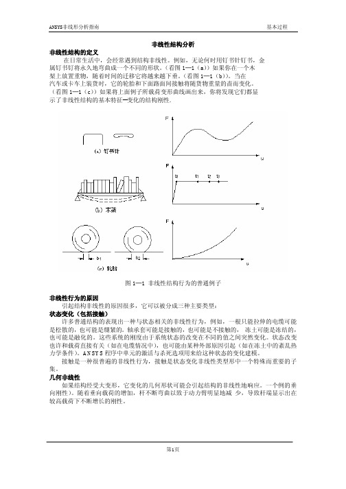
非线性结构分析非线性结构的定义在日常生活中,会经常遇到结构非线性。
例如,无论何时用钉书针钉书,金属钉书钉将永久地弯曲成一个不同的形状。
(看图1─1(a))如果你在一个木架上放置重物,随着时间的迁移它将越来越下垂。
(看图1─1(b))。
当在汽车或卡车上装货时,它的轮胎和下面路面间接触将随货物重量的啬而变化。
(看图1─1(c))如果将上面例子所载荷变形曲线画出来,你将发现它们都显示了非线性结构的基本特征--变化的结构刚性.图1─1 非线性结构行为的普通例子非线性行为的原因引起结构非线性的原因很多,它可以被分成三种主要类型:状态变化(包括接触)许多普通结构的表现出一种与状态相关的非线性行为,例如,一根只能拉伸的电缆可能是松散的,也可能是绷紧的。
轴承套可能是接触的,也可能是不接触的,冻土可能是冻结的,也可能是融化的。
这些系统的刚度由于系统状态的改变在不同的值之间突然变化。
状态改变也许和载荷直接有关(如在电缆情况中),也可能由某种外部原因引起(如在冻土中的紊乱热力学条件)。
ANSYS程序中单元的激活与杀死选项用来给这种状态的变化建模。
接触是一种很普遍的非线性行为,接触是状态变化非线性类型形中一个特殊而重要的子集。
几何非线性如果结构经受大变形,它变化的几何形状可能会引起结构的非线性地响应。
一个例的垂向刚性)。
随着垂向载荷的增加,杆不断弯曲以致于动力臂明显地减少,导致杆端显示出在较高载荷下不断增长的刚性。
图1─2 钓鱼杆示范几何非线性材料非线性非线性的应力──应变关系是结构非线性名的常见原因。
许多因素可以影响材料的应力──应变性质,包括加载历史(如在弹─塑性响应状况下),环境状况(如温度),加载的时间总量(如在蠕变响应状况下)。
牛顿一拉森方法ANSYS程序的方程求解器计算一系列的联立线性方程来预测工程系统的响应。
然而,非线性结构的行为不能直接用这样一系列的线性方程表示。
需要一系列的带校正的线性近似来求解非线性问题。
基于ANSYS的武汉长江二桥非线性有限元分析

6 ;B SE N 进行 求解 索 力迭 代 ( 从计 算结果 中提 取斜 拉索 索力 , ( T 初始 索力 + 是 否小于 允许 值 ( 若大 于允 许值 , 则将 ) 计算 所 得的 索 力 作 为成 桥 索 力 , 修改 斜 拉 索单 元
第" 卷增刊 " / 年 ’ " # # $ "月
华
中
科 技 大 学 学 报) 城市科学版 + V (W X Y96 K() 9F Z [ G6 \ ] ^ G \ ^E _ ] I ] W G +
SW ‘ ( " /6 a b ( " A ^ \ ( " # # $
基 于
0 1 2 3 2的
武 汉 长 江 二 桥 非 线 性 有 限 元 分 析
斜拉 桥主要 的组 成构 件是 梁 8 索和 塔 , 理 想的 受力 状 态是 斜 拉 索受 拉 , 主 梁 和 索塔 尽 可 能地 承 受压 力 而不 承 受 弯矩 作 用 ( 因 而 斜拉 桥 的 结构 表 现出 以 下一 些 特 点 ! 利用 一 系 列 拉索 代 替 相应 的 支承 结 构 , 大 大减 少 了 主 梁的 弯 矩 , 降 低梁 高 , 节 省了 材料 可以 人为 地对 拉索 索力 进行 调整 , 达到 改变 全桥 受力状 态使 其最 大限 度满 足设 计者 期望 的受 力状 态 斜 拉桥 是一 种自 锚体 系 , 下 部结 构比 较经 济 ( 因 此, 在 跨径 . 斜 # # < ’= # #> 的范 围内 , 拉桥 为 最常 见 的 桥梁 结 构 形 式 ( 作为 一 种 高次 超 静定 结 构 , 其计 算 分 析的 精 确 程 度直 接 关 系到 设 计的 优 劣与 施 工 过程 中 的 安 全 ( 斜拉 桥 跨 度不 断 增大 , 整 体 结构 在 恒 载及 拉 索 张 拉力 作 用 下表 现 出明显的非线性特征! 斜 拉 索 垂 度 效 应梁柱效 应大 位移 效应 ( 在总 结 前 人经 验 的 基 础上 , 提 出 了 一套 全 面 考虑 斜 拉桥 几 何 非线 性 因 素 的有 限 元 方法 , 综合 考虑 了梁 索塔三 者联 结的 边界 条件 以及 它们 的受 力特 点 , 特 别是 预应 力筋 的作 用 8 拉 索初 始张 力等 因素 , 应用 大 型 通 用 有 限 元软 件 456 76对 其 进 行了 详细 的空间 有限 元非 线性 分析 (
ANSYS非线性命令解析
ANSYS非线性命令解析〔1ANSYS应用基于问题物理特性的自动求解控制方法,把各种非线性分析控制参数设置到合适的值。
如果用户对这些设置不满意,还可以手工设置。
下列命令的缺省设置已进行了优化处理:AUTOTS PRED MONITORDELTIM NROPT NEQITNSUBST TINTP SSTIFCNVTOL CUTCONTROL KBCLNSRCH OPNCONTROL EQSLVARCLEN CDWRITE LSWRITE这些命令及其设置在将在后面讨论。
参见《ANSYS Commands Reference》。
如果用户选择自己的设置而不是ANSYS的缺省设置,或希望用以前版本的ANSYS的输入列表,则可用/ SOLU 模块的SOLCONTROL ,OFF命令,或在/ BATCH 命令后用/ CONFIG ,NLCONTROL,OFF命令。
参见SOLCONTROL 命令的详细描述。
ANSYS对下面的分析激活自动求解控制单场的非线性或瞬态结构以及固体力学分析,在求解自由度为UX、UY、UZ、ROTX、ROTY、ROTZ 的结合时;单场的非线性或瞬态热分析,在求解自由度为TEMP时;注意-- 本章后面讨论的求解控制对话框,不能对热分析做设置。
用户必须应用标准的ANSYS求解命令或GUI来设置。
2.2 非线性静态分析步骤尽管非线性分析比线性分析变得更加复杂,但处理基本相同。
只是在非线形分析的过程中,添加了需要的非线形特性。
非线性静态分析是静态分析的一种特殊形式。
如同任何静态分析,处理流程主要由以下主要步骤组成:建模;设置求解控制;设置附加求解控制;加载;求解;考察结果。
2.2.1 建模这一步对线性和非线性分析基本上是一样的,尽管非线性分析在这一步中可能包括特殊的单元或非线性材料性质,参考§4《材料非线性分析》,和§6.1《单元非线性》。
如果模型中包含大应变效应,应力─应变数据必须依据真实应力和真实<或对数>应变表示。
【ANSYS非线性分析】4-非线性分析方法
01112121222y y d N d d R d M d d R ελφ⎧⎫
⎧⎫⎡⎤⎧⎫=∆+⎨⎬⎨⎬⎨⎬⎢⎥
⎣⎦⎩⎭
⎩⎭⎩⎭ 改写为,
11112021222y y d N R d d d d M R d d εφλ-⎡⎤⎧⎫⎧⎫
⎧⎫=-⎨⎬⎨⎬⎨⎬⎢⎥
-⎩⎭⎩⎭⎩⎭
⎣⎦ 求解过程中,可控制d φy 的值,求出相应的0d ε及荷载增量比例因子d λ。
由于ij d 与截面应变平面有关,需要迭代才能使截面补平衡力12,R R 趋近于零。
图4-9 位移控制法 在结构分析中控制指定位移增量,则P —δ曲线的下降段不难求得。
将底端固定顶端自由的柱,在柱顶端施加水平荷载,将柱的加载点处换为支座,而分析时控制该支座位移并求出该支座的反力,图4—9表示了得到的全过程分析P-δ曲线。
对于一般结构,将刚度矩阵重新排列,使得选择的控制位移排到最后,将原矩阵分块表示成以下形式,
111211121
22222K K du P R K K du P R ⎡⎤⎧⎫⎧⎫⎧⎫=∆+⎨⎬⎨⎬⎨⎬⎢⎥⎣⎦⎩⎭⎩⎭⎩⎭
λ 改写方程为,
11
11121221
2222K P R K du du K P R K -⎡⎤⎧⎫⎧⎫⎧⎫
=-⎨⎬⎨⎬⎨⎬⎢⎥-∆⎩⎭⎣⎦⎩⎭⎩⎭
λ 需要指出的是,改写以后的系数矩阵是不对称的,也不是带状的,求解时需要较多的存储单元。
§4.5.4 修正完善后的弧长法 1.弧长法的基本原理
仍从结构增量平衡方程:{}{}{}11i i i i K w P g --=-∆∆λ∆。
ANSYS非线性分析(控制选项)

ANSYS非线性分析(控制选项)1、非线性分析(1)牛顿-拉普森选项(NROPT)仅在非线性分析中使用这个选项,。
这个选项制定在求解期间每隔多长时间修正一次正切矩阵。
可以指定下列值中的一个: 程序选择(NROPT,AUTO)。
程序根据模型中存在的非线性种类自动选用这些选项中的一个。
在需要时牛顿-拉普森方法将自动激活自适应下降。
完全牛顿-拉普森选项(NROPT,FULL)。
程序使用完全的牛顿-拉普森处理方法,在这种处理方法中每进行一次平衡迭代都修改刚度矩阵一次。
如果自适应下降是关闭的,程序每一次平衡迭代都使用正切刚度矩阵。
如果自适应下降是打开的,只要迭代保持稳定,程序仅适用正切刚度矩阵。
如果在某一次迭代过程中检测到发散倾向,程序将抛弃发散的迭代并重新开始求解,此时应用正切和正割刚度矩阵的加权组合。
当迭代重新回到收敛模式是程序将重新开始使用正切刚度矩阵。
对复杂的非线性问题自适应下降统称能提高程序获得收敛的能力。
修正牛顿-拉普森选项(NROPT,MODL)。
程序使用修正的牛顿-拉普森方法,在这种方法中正切刚度矩阵在每一步中都被修正,在一个子步的平衡迭代期间矩阵不被改变。
这个选项不适应于大变形分析,而且无法使用自适应下降。
初始刚度(NROPT,INIT)。
程序在每一次平衡迭代中都使用初始刚度矩阵,该选项可以使迭代过程更容易收敛,但需要更多迭代次数得到收敛。
该选项不适用于大变形分析,求自适应下降不可用。
(2)指定载荷步选项这些选项可以在任何载荷中改变。
下列选项适用于非线性分析:l 普通选项在普通选项包括:Time(TIME)。
ANSYS程序借助在每一个载荷步末端指定TIME参数识别出载荷步和子步。
使用TIME命令可以用来定义受某些实际物理量限制的TIME值。
程序通过这个选项来指定载荷步的末端时间。
时间步的数目(NSUBST)和时间步长(DELTIM)。
非线性分析要求在每一个载荷步内有多个子步或时间步,从而ANSYS可以逐渐施加所给定的载荷,逐步得到精确解。
Ansys Workbench非线性分析 牛顿辛普森法过程
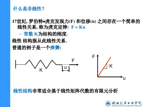
然而, 相当多的结构在力和位移之间没有线性关系 因为此类结构的 F-u 图不是直线, 这样的结构称为非线性结构 . – 刚度不再是一个常数K; 它成为施加载荷的函数, KT (切 线刚度). 普通的例子是韧性金属的拉伸试验:
载荷位移曲线
Fa Fnr
R
下一次迭代用刚度矩阵
u0 △ u u1
u0: 所设初始位移值
u
位移
KT :切向刚度
u1: 下次迭代位移值
R F a F nr
收敛: Newton-Raphson法需要一个收敛的度量以决定 何时结束迭代。给定节点Fa,节点力Fnr ,在一个体 中,节点载荷必须与节点力平衡
高级接触选项包括: 自动探测尺寸 Auto detection dimension and slider 非对称接触Asymmetric contact 接触结果工具Contact results tool 接触算法contact formulations Pinball 控制
膜片弹簧接触设置
带支撑环的膜片弹簧边界条件及求解设置
3 2 F1 269.991 2981 1 9238 1
膜片弹簧大端载荷-位移曲线
3 2 F1 269.991 2981 1 9238 1
注:膜片弹簧载荷挠度曲线为非线性,是由于大变形引起 的几何非线性,但材料始终发生的是弹性变形,没有发生 塑性变形
回忆材料力学中低碳钢力学性能试验
ansys非线性分析例子

4.9 选择Main Menu>Solution>Load Step Opts>Write LS File,在对话框中输入 3,单击OK,如下图所 示
4.10 选择Main Menu>Solution>Solve >From LS Files,弹 出如下对话框,并进 行如下设置单击ok
5.1 选择Main Menu>General Postproc>Read Results>First Set,读取第一个载荷步的求解结果 5.2 Main Menu>General Postproc>plot Results>Contour Plot>Nodal Solu,弹出如下对 话框,并进行如下页的设置
/GO D,P51X, , , , , ,ALL, , , , , FLST,2,1,1,ORDE,1 FITEM,2,10 !* /GO F,P51X,FY,-12 FLST,2,1,1,ORDE,1 FITEM,2,10 !* /GO F,P51X,FX,0.05 LSWRITE,1, FLST,2,1,1,ORDE,1 FITEM,2,10 !* /GO F,P51X,FY,-13 FLST,2,1,1,ORDE,1 FITEM,2,10 !* /GO F,P51X,FX,0.05 LSWRITE,2, FLST,2,1,1,ORDE,1 FITEM,2,10 !*
1.1 单击 开始>所有 程序 >ansys12.1>mench anical APDL Product Launcher窗口如左图。 在working Directory 栏中设置工作目录, 在job name中输入如 左图所示的工作名。 单击Run,进入ansys。
ANSYS非线性分析

16
11.2 结构非线性分析
• 1.进入求解控制对话框 ➢ GUI:【Main Menu】/【Solution】/【Analysis Type】/
表11-3 Advanced NL标签选项
选项 Termination Criteria Arc-length options
用途 终止分析结束准则 激活和终止弧长法控制
28
11.2 结构非线性分析
图11-5 Advanced NL标签界面
29
11.2 结构非线性分析
➢ 11.2.1.3 设置其它求解选项 • 其他求解选项很少使用,并且其默认值设置都很少改变,
33
11.2 结构非线性分析
➢ (3) 预应力效应计算 • 这一选项用来在同一模型中执行预应力分析,如预应力模
型的分析。缺省值为 OFF。应力刚度效应和预应力效应计 算二者都控制应力刚度矩阵的生成,因此在一个分析中不 以同时应用。如二者都指定,则最后选项将覆盖前者。 ➢ 命令:PSTRES ➢ GUI:【Main Menu】/【Solution】/【Unabridged Menu】/【Analysis Options】
32
11.2 结构非线性分析
➢ (2)Newton-Raphson选项 • 这一选项只能用于非线性分析中,它说明在求解时切线矩
阵如何修正。在存在非线性时,ANSYS的自动求解控制 将应用自适应下降关闭的完全牛顿-拉普森选项。但在应 用节点-节点,节点-面接触单元的有摩擦接触分析中,自 适应下降功能是自动打开的。 ➢ 命令:NROPT ➢ GUI:【Main Menu】/【Solution】/【Unabridged Menu】/【Analysis Options】
ANSYS结构非线性分析指南_第二章
第二章开始结构非线性分析2.1 在ANSYS中执行非线性分析ANSYS应用基于问题物理特性的自动求解控制方法,把各种非线性分析控制参数设置到合适的值。
如果用户对这些设置不满意,还可以手工设置。
下列命令的缺省设置已进行了优化处理: AUTOTS PRED MONITORDELTIM NROPT NEQITNSUBST TINTP SSTIFCNVTOL CUTCONTROL KBCLNSRCH OPNCONTROL EQSLVARCLEN CDWRITE LSWRITE这些命令及其设置在将在后面讨论。
参见《ANSYS Commands Reference》。
如果用户选择自己的设置而不是ANSYS的缺省设置,或希望用以前版本的ANSYS的输入列表,则可用/SOLU模块的SOLCONTROL,OFF命令,或在/BATCH命令后用/CONFIG,NLCONTROL,OFF命令。
参见SOLCONTROL命令的详细描述。
ANSYS对下面的分析激活自动求解控制:∙单场的非线性或瞬态结构以及固体力学分析,在求解自由度为UX、UY、UZ、ROTX、ROTY、ROTZ 的结合时;∙单场的非线性或瞬态热分析,在求解自由度为TEMP时;注意--本章后面讨论的求解控制对话框,不能对热分析做设置。
用户必须应用标准的ANSYS求解命令或GUI来设置。
2.2 非线性静态分析步骤尽管非线性分析比线性分析变得更加复杂,但处理基本相同。
只是在非线形分析的过程中,添加了需要的非线形特性。
非线性静态分析是静态分析的一种特殊形式。
如同任何静态分析,处理流程主要由以下主要步骤组成:∙建模;∙设置求解控制;∙设置附加求解控制;∙加载;∙求解;∙考察结果。
2.2.1 建模这一步对线性和非线性分析基本上是一样的,尽管非线性分析在这一步中可能包括特殊的单元或非线性材料性质,参考§4《材料非线性分析》,和§6.1《单元非线性》。
如果模型中包含大应变效应,应力─应变数据必须依据真实应力和真实(或对数)应变表示。
Ansys57线性和非线性结构静力分析指南

ANSYS 5.7线性和非线性 结构静力分析指南Chen Woo 译摘自Structural Analysis GuideANSYS Release 5.7前言ANSYS公司曾经推出一套中文版的ANSYS文档资料。
但对于目前发行的ANSYS 5.7,我们未见到任何相应版本的中文说明书。
这是一个重大缺陷。
为此,本人花了一些时间,把“Structural Analysis Guide(ANSYS Release 5.7)”的一部分内容翻译成中文。
在翻译时,主要的准则是忠实。
目前这个文稿还只是一个很粗略的草稿,以后还需要进一步修改。
只是本人时间有限,只能利用业余时间来做这项工作,因此先匆忙拿来献丑。
希望广大用户和读者喜欢,同时也希望大家帮助。
如有任何建议,请通知本人(chenwoo@),不胜感激。
Chen Woo于2001-08-18目录1 结构分析概述_____________________________________________________________________6 1.1 结构分析定义__________________________________________________________________6 1.2 结构分析的类型________________________________________________________________6 1.3 结构分析所应用的单元__________________________________________________________6 1.4 材料模式界面__________________________________________________________________81.5 求解方法______________________________________________________________________82 结构线性静力分析_________________________________________________________________9 2.1 静力分析的定义________________________________________________________________9 2.2 线性静力分析与非线性静力分析__________________________________________________9 2.3 静力分析的例子________________________________________________________________9 2.4 静力分析的求解步骤____________________________________________________________92.4.1 建模______________________________________________________________________92.4.2 设置求解控制_____________________________________________________________102.4.3设置其他求解选项_________________________________________________________132.4.4施加荷载_________________________________________________________________142.4.5求解_____________________________________________________________________162.4.6检查分析结果_____________________________________________________________17 2.5静力分析示例(GUI方法)________________________________________________________192.5.1 问题描述_________________________________________________________________192.5.2 几何和材料特性___________________________________________________________192.5.3 求解_____________________________________________________________________19 2.6静力分析示例(命令流方法)_____________________________________________________27 2.7何处找到更多的静力分析示例___________________________________________________29 7 屈曲分析________________________________________________________________________31 7.1 屈曲分析的概念_______________________________________________________________31 7.2 屈曲分析的类型_______________________________________________________________317.2.1 非线性屈曲分析___________________________________________________________317.2.2 特征值屈曲分析___________________________________________________________31 7.3 屈曲分析的用到的命令_________________________________________________________31 7.4 非线性屈曲分析的过程_________________________________________________________317.4.1 施加载荷增量_____________________________________________________________327.4.2 自动时间步长功能_________________________________________________________327.4.3 注意事项_________________________________________________________________327.4.4 其他_____________________________________________________________________32 7.5 特征值(线性)屈曲分析_________________________________________________________337.5.1 建立模型_________________________________________________________________337.5.2 获得静力解_______________________________________________________________337.5.3 获得特征值屈曲解_________________________________________________________347.5.4 扩展解___________________________________________________________________357.5.5 查看结果_________________________________________________________________367.6 特征值屈曲分析实例(GUI方法)__________________________________________________367.6.1 问题描述_________________________________________________________________367.6.2 问题详细说明_____________________________________________________________377.6.3 求解步骤_________________________________________________________________377.7 屈曲分析示例(命令流方法)_____________________________________________________397.8 何处找到更多的示例___________________________________________________________408 非线性结构分析__________________________________________________________________41 8.1 结构非线性的定义_____________________________________________________________418.1.1 非线性行为的原因_________________________________________________________418.1.2 非线性分析的基本信息_____________________________________________________428.2 几何非线性的应用_____________________________________________________________448.2.1 应力-应变_________________________________________________________________448.2.2 应力刚化_________________________________________________________________458.2.3 旋转软化_________________________________________________________________458.3 材料非线性的模拟_____________________________________________________________458.3.1 非线性材料_______________________________________________________________458.4 在ANSYS中执行非线性分析____________________________________________________628.5 非线性静态分析步骤___________________________________________________________628.5.1 建模_____________________________________________________________________628.5.2 设置求解控制_____________________________________________________________628.5.3 设置附加求解选项_________________________________________________________668.5.4 施加荷载_________________________________________________________________688.5.5 求解_____________________________________________________________________698.5.6 考察结果_________________________________________________________________698.5.7 终止正在运行的工作,重起动_________________________________________________718.6 非线性瞬态分析步骤___________________________________________________________71§8.6.1建模____________________________________________________________________71 §8.6.2施加荷载和求解__________________________________________________________71 §8.6.3观察结果________________________________________________________________738.7 非线性瞬态分析示例(输入文件列表)_____________________________________________738.8 重启动_______________________________________________________________________748.9 非线性(状态改变)单元_________________________________________________________74§8.9.1单元生死________________________________________________________________748.10 非线性分析的提示和指南______________________________________________________748.10.1__________________________________________________________________________748.10.2 克服收敛问题____________________________________________________________758.11 非线性(静态)分析示例(GUI方法)_______________________________________________798.11.1 问题描述________________________________________________________________798.11.2 基本数据________________________________________________________________798.11.3 问题求解________________________________________________________________808.12 非线性(静态)分析示例(批处理方法)_____________________________________________848.13 其它例子____________________________________________________________________889接触分析________________________________________________________________________909.1概述_________________________________________________________________________90 9.1.1显式动态接触分析能力_____________________________________________________909.2一般接触分类_________________________________________________________________909.3ANSYS接触分析功能__________________________________________________________90 9.3.1面─面的接触单元_________________________________________________________91 9.3.2点─面接触单元___________________________________________________________92 9.3.3点─点接触单元___________________________________________________________929.4面─面的接触分析_____________________________________________________________92 9.4.1应用面-面接触单元_________________________________________________________92 9.4.2接触分析的步骤___________________________________________________________93 9.4.3建立模型几何实体和划分网格_______________________________________________93 9.4.4识别接触对_______________________________________________________________93 9.4.5指定接触面和目标面_______________________________________________________94 9.4.6不对称接触与对称接触_____________________________________________________94 9.4.7定义目标面_______________________________________________________________94 9.4.8定义柔体的接触面_________________________________________________________98 9.4.9设置实常数和单元关键字__________________________________________________100 9.4.10控制刚性目标面的运动(刚体-柔体接触)_____________________________________109 9.4.11温度接触建模___________________________________________________________110 9.4.12给变形体单元加必要的边界条件___________________________________________111 9.4.13定义求解和载荷步选项___________________________________________________112 9.4.14求解___________________________________________________________________113 9.4.15检查结果_______________________________________________________________1139.5点-面接触分析_______________________________________________________________116 9.5.1使用点─面的接触单元____________________________________________________116 9.5.2点─面接触分析的步骤____________________________________________________1169.6点-点的接触分析____________________________________________________________127§9.6.1 建立几何实体及分网_____________________________________________________127 §9.6.2 生成接触单元___________________________________________________________128 §9.6.3 定义接触的法线方向_____________________________________________________128 §9.6.4定义初始界面或间隙_____________________________________________________129 §9.6.5选择接触算法___________________________________________________________129 §9.6.6施加必要的边界条件_____________________________________________________130 §9.6.7定义求解选项___________________________________________________________130 §9.6.8求解___________________________________________________________________131 §9.6.9检查结果_______________________________________________________________1311 结构分析概述1.1 结构分析定义结构分析是有限元分析方法最常用的一个应用领域。
ANSYS模态分析教程及实例讲解

任何结构都具有其固有频率(固有周期),其值由其本身的结构所决定 自由振动是一种无衰减力的振动状态,它将永远不停地振动下去。
频率分析的相关知识
• 静力分析中,节点位移是主要的未知量。[K]d=F中[K]为刚度 矩阵,d为节点位移的未知量,而F为节点载荷的已知量。
要点:振动的形式(振形)称为振动模态。 一般从低频开始,称为1阶、2阶、3阶……固有频率,并且具
有与各个固有频率对应的振动模态。
频率分析的相关知识
• 共振(以荡秋千为例) –荡得好的人荡几下马上就能荡得很高
–这是因为与秋千摆动的节拍和时间配合起来的原因。 –换句话说,与秋千的固有频率(固有周期)相配合,这
– 小变形 – 弹性范围内的应变和应力 – 没有诸如两物体接触或分离时的刚度突变。
应力
弹性模量 (EX)
应变
准备工作
A. 哪种分析类型?
• 如果加载引起结构刚度的显著变化,必须进行 非线性分析。引起结构刚度显著变化的典型因 素有: – 应变超过弹性范围(塑性) – 大变形,例如承载的鱼竿 – 两体之间的接触
• 在动力学分析中,增加阻尼矩阵[C]和质量矩阵[M]
上式为典型的在有阻尼的交迫振动方程。当缺少阻尼及外力 时,该缺少阻尼及外力时(自由振动),该方程式简化为
频率分析的相关知识
• 固有振动模态(以弦的振动为例)
– 两端被固定住的弦,以手指弹一下张紧的弦,弦则振动 起来,振动在空气中传播发出声音。弦以下图所示的各
第三讲模态分析
• 在开始ANSYS分析之前,您需要作一些决定, 诸如分析类型及所要创建模型的类型。
• 标题如下:
8.6ANSYS非线性静力分析步骤帮助学习

8.6. Performing a Nonlinear Static AnalysisThe procedure for performing a nonlinear static analysis consists of these tasks:∙Build the Model∙Set Solution Controls∙Set Additional Solution Options∙Apply the Loads∙Solve the Analysis∙Review the Results∙Terminating a Running Job; Restarting8.6.1. Build the ModelThis step is essentially the same for both linear and nonlinear analyses, although a nonlinear analysis might include special elements or nonlinear material properties. See Using Nonlinear (Changing-Status) Elements, and Modeling Material Nonlinearities, for more details. If your analysis includes large-strain effects, your stress-strain data must be expressed in terms of true stress and true (or logarithmic) strain. For more information on building models in ANSYS, see the Modeling and Meshing Guide.After you have created a model in ANSYS, you set solution controls (analysis type, analysis options, load step options, and so on), apply loads, and solve. A nonlinear solution will differ from a linear solution in that it often requires multiple load increments, and always requires equilibrium iterations. The general procedure for performing these tasks follows. See Sample Nonlinear Analysis (GUI Method)for a sample problem that walks you through a specific nonlinear analysis.8.6.2. Set Solution ControlsSetting solution controls for a nonlinear analysis involves the same options and method of access (the Solution Controls dialog box) as those used for a linear structural static analysis. For a nonlinear analysis, the default settings in the Solution Controls dialog box are essentially the same settings employed by the automatic solution control method described in Running a Nonlinear Analysis in ANSYS. See the following sections in Structural Static Analysis, with exceptions noted:∙Set Solution Controls∙Access the Solution Controls Dialog Box∙Using the Basic Tab∙The Transient Tab∙Using the Sol'n Options Tab∙Using the Nonlinear Tab∙Using the Advanced NL Tab8.6.2.1. Using the Basic Tab: Special ConsiderationsSpecial considerations for setting these options in a nonlinear structural static analysis include:∙When setting ANTYPE and NLGEOM, choose Large Displacement Static if you are performing a new analysis. (But, keep in mind that not all nonlinear analyses will produce large deformations. See Using Geometric Nonlinearities for further discussion of largedeformations.) Choose Restart Current Analysis if you want torestart a failed nonlinear analysis. You cannot change this setting after the first load step (that is, after you issue your first SOLVEcommand). You will usually choose to do a new analysis, rather thana restart. Restarts are discussed in the Basic Analysis Guide.∙When working with time settings, remember that these options can be changed at any load step. See "Loading" in the Basic Analysis Guide for more information on these options. Advancedtime/frequency options, in addition to those available on theSolution Controls dialog box, are discussed in Advanced Load Step Options You Can Set on the Solution Controls Dialog Box.A nonlinear analysis requires multiple substeps (or time steps; thetwo terms are equivalent) within each load step so that ANSYS can apply the specified loads gradually and obtain an accurate solution.The NSUBST and DELTIM commands both achieve the same effect(establishing a load step's starting, minimum, and maximum stepsize), but by reciprocal means. NSUBST defines the number ofsubsteps to be taken within a load step, whereas DELTIM defines the time step size explicitly. If automatic time stepping is off[AUTOTS], then the starting substep size is used throughout the load step.∙OUTRES controls the data on the results file (Jobname.RST). By default, only the last substep is written to the results file ina nonlinear analysis.Only 1000 results sets (substeps) can be written to the results file, but you can use the command /CONFIG,NRES to increase the limit (see the Basic Analysis Guide).8.6.2.2. Advanced Analysis Options分析选项You Can Set on the Solution Controls Dialog BoxThe following sections provide more detail about some of the advanced analysis options that you can set on the Solution Controls dialog box.8.6.2.2.1. Equation SolverANSYS' automatic solution control activates the sparse direct solver (EQSLV,SPARSE) for most cases. Other options include the PCG and ICCG solvers. For applications using solid elements (for example, SOLID92 or SOLID45), the PCG solver may be faster, especially for 3-D modeling.If using the PCG solver, you may be able to reduce memory usage via the MSAVE command. The MSAVE command triggers an element-by-element approach for the parts of the model that use SOLID45, SOLID92, SOLID95, SOLID185, SOLID186, SOLID187SOLID272, SOLID273, and/or SOLID285 elements with linear material properties. (MSAVE does not support the layered option of the SOLID185 and SOLID186 elements.) To use MSAVE, you must be performing a static or a modal analysis with PCG Lanczos enabled. When using SOLID185, SOLID186, and/or SOLID187, only small strain (NLGEOM,OFF) analyses are allowed. Other parts of the model that do not meet the above criteria are solved using global assembly for the stiffness matrix. MSAVE,ON can result in a memory savings of up to 70 percent for the part of the model that meets the criteria, although the solution time may increase depending on the capabilities of your computer and the element options selected.The sparse direct solver, in sharp contrast to the iterative solvers included in ANSYS, is a robust solver. Although the PCG solver can solve indefinite matrix equations, when the PCG solver encounters anill-conditioned matrix, the solver will iterate to the specified number of iterations and stop if it fails to converge. When this happens, it triggers bisection. After completing the bisection, the solver continues the solution if the resulting matrix is well-conditioned. Eventually, the entire nonlinear load step can be solved.Use the following guidelines for selecting either the sparse or the PCG solver for nonlinear structural analysis:∙If it is a beam/shell or beam/shell and solid structure, choose the sparse direct solver.∙If it is a 3-D solid structure and the number of DOF is relatively large (that is, 200,000 or more DOF), choose the PCG solver.∙If the problem is ill-conditioned (triggered by poor element shapes), or has a big difference in material properties in different regions of the model, or has insufficient displacement boundaryconstraints, choose the sparse direct solver.8.6.2.3. Advanced Load Step Options载荷步选项 You Can Set on the Solution Controls Dialog BoxThe following sections provide more detail about some of the advanced load step options that you can set on the Solution Controls dialog box.8.6.2.3.1. Automatic Time SteppingANSYS' automatic solution control turns automatic time stepping on [AUTOTS,ON]. An internal auto-time step scheme ensures that the time step variation is neither too aggressive (resulting in many bisection/cutbacks) nor too conservative (time step size is too small). At the end of a time step, the size of the next time step is predicted based on four factors:∙Number of equilibrium iterations used in the last time step (more iterations cause the time step size to be reduced) ∙Predictions for nonlinear element status change (time step sizes are decreased when a status change is imminent)∙Size of the plastic strain increment∙Size of the creep strain increment8.6.2.3.2. Convergence CriteriaThe program will continue to do equilibrium iterations until the convergence criteria [CNVTOL] are satisfied (or until the maximum number of equilibrium equations is reached [NEQIT]). You can define custom criteria if the default settings are not suitable.ANSYS' automatic solution control uses L2-norm of force (and moment) tolerance (TOLER) equal to 0.5%, a setting that is appropriate for most cases. In most cases, an L2-norm check on displacement with TOLER equal to 5% is also used in addition to the force norm check. The check that the displacements are loosely set serves as a double-check on convergence.By default, the program will check for force (and, when rotational degrees of freedom are active, moment) convergence by comparing the square rootsum of the squares (SRSS) of the force imbalances against the product of VALUE*TOLER. The default value of VALUE is the SRSS of the applied loads (or, for applied displacements, of the Newton-Raphson restoring forces), or MINREF (which defaults to 0.01), whichever is greater. The default value of TOLER is 0.005. If SOLCONTROL,OFF, TOLER defaults to 0.001 and MINREF defaults to 1.0 for force convergence.You should almost always use force convergence checking. You can also add displacement (and, when applicable, rotation) convergence checking. For displacements, the program bases convergence checking on the change in deflections (Δu) between the current (i) and the previous (i-1)iterations: Δu=ui -ui-1.Note: If you explicitly define any custom convergence criteria [CNVTOL], the entire default criteria will be overwritten. Thus, if you define displacement convergence checking, you will have to redefine force convergence checking. (Use multiple CNVTOL commands to definemultiple convergence criteria.)Using tighter convergence criteria will improve the accuracy of your results, but at the cost of more equilibrium iterations. If you want to tighten (or loosen, which is not recommended) your criteria, you should change TOLER by one or two orders of magnitude. In general, you should continue to use the default value of VALUE; that is, change the convergence criteria by adjusting TOLER, not VALUE. You should make certain that the default value of MINREF= 0.001 makes sense in the context of your analysis. If your analysis uses certain sets of units or has very low load levels, you might want to specify a smaller value for MINREF.Also, we do not recommend putting two or more disjointed structures into one model for a nonlinear analysis because the convergence check tries to relate these disjointed structures, often producing some unwanted residual force.Checking Convergence in a Single and Multi-DOF SystemTo check convergence in a single degree of freedom (DOF) system, you compute the force (and moment) imbalance for the one DOF, and compare this value against the established convergence criteria (VALUE*TOLER). (You can also perform a similar check for displacement (and rotation) convergence for your single DOF.) However, in a multi-DOF system, you might want to use a different method of comparison.The ANSYS program provides three different vector norms to use for convergence checking:∙The infinite norm repeats the single-DOF check at each DOF in your model.∙The L1 norm compares the convergence criterion against the sum of the absolute values of force (and moment) imbalance for all DOFs.∙The L2 norm performs the convergence check using the square root sum of the squares of the force (and moment) imbalances for all DOFs.(Of course, additional L1 or L2 checking can be performed for adisplacement convergence check.)ExampleFor the following example, the substep will be considered to be converged if the out-of-balance force (checked at each DOF separately) is less than or equal to 5000*0.0005 (that is, 2.5), and if the change in displacements (checked as the square root sum of the squares) is less than or equal to 10*0.001 (that is, 0.01).CNVTOL,F,5000,0.0005,0CNVTOL,U,10,0.001,28.6.2.3.3. Maximum Number of Equilibrium IterationsANSYS' automatic solution control sets the value of NEQIT to between 15 and 26 iterations, depending upon the physics of the problem. The idea is to employ a small time step with fewer quadratically converging iterations.This option limits the maximum number of equilibrium iterations to be performed at each substep (default = 25 if solution control is off). If the convergence criteria have not been satisfied within this number of equilibrium iterations, and if auto time stepping is on [AUTOTS], the analysis will attempt to bisect. If bisection is not possible, then the analysis will either terminate or move on to the next load step, according to the instructions you issue in the NCNV command.8.6.2.3.4. Predictor-Corrector OptionANSYS' automatic solution control will set PRED,ON if there are no SOLID65 elements present. If the time step size is reduced greatly in the current substep, PRED is turned off. For transient analysis, the predictor is also turned off.You can activate a predictor on the DOF solution for the first equilibrium iteration of each substep. This feature accelerates convergence and is particularly useful if nonlinear response is relatively smooth, as in the case of ramped loads.8.6.2.3.5. VT AcceleratorThis option selects an advanced predictor-corrector algorithm based on Variational Technology to reduce the overall number of iterations [STAOPT,VT for static analyses, TRNOPT,VT for transient]. This option requires an HPC license. It is applicable to analyses that include large deflection [NLGEOM], hyperelasticity, viscoelasticity, and creep nonlinearities. Rate-independent plasticity and nonlinear contact analyses may not show any improvement in convergence rates; however, you may choose this option with these nonlinearities if you wish to rerun the analysis with changes to the input parameters later.8.6.2.3.6. Line Search OptionANSYS' automatic solution control will toggle line search on and off as needed. For most contact problems, LNSRCH is toggled on. For mostnon-contact problems, LNSRCH is toggled off.This convergence-enhancement tool multiplies the calculated displacement increment by a program-calculated scale factor (having a value between 0 and 1), whenever a stiffening response is detected. Because the line search algorithm is intended to be an alternative to the adaptive descent option [NROPT], adaptive descent is not automatically activated if the line search option is on. We do not recommend activating both line search and adaptive descent simultaneously.When an imposed displacement exists, a run cannot converge until at least one of the iterations has a line search value of 1. ANSYS scales the entire ΔU vector, including the imposed displacement value; otherwise, a "small" displacement would occur everywhere except at the imposed DOF. Until one of the iterations has a line search value of 1, ANSYS does not impose the full value of the displacement.8.6.2.3.7. Cutback CriteriaFor finer control over bisections and cutback in time step size, use [CUTCONTROL, Lab, VALUE, Option]. By default, for Lab= PLSLIMIT (maximum plastic strain increment limit), VALUE is set to 15%. This field is set to such a large value for avoiding unnecessary bisections caused by high plastic strain due to a local singularity which is not normally of interestto the user. For explicit creep (Option= 0), Lab= CRPLIM (creep increment limit) and VALUE is set to 10%. This is a reasonable limit for creep analysis. For implicit creep (Option = 1), there is no maximum creep criteria by default. You can however, specify any creep ratio control. The number of points per cycle for second order dynamic equations (Lab = NPOINT) is set to VALUE = 13 by default to gain efficiency at little cost to accuracy.8.6.3. Set Additional Solution OptionsThis section discusses additional options that you can set for the solution. These options do not appear on the Solution Controls dialog box because they are used infrequently, and their default settings rarely need to be changed. ANSYS menu paths are provided in this section to help you access these options for those cases in which you choose to override the ANSYS-assigned defaults.8.6.3.1. Advanced Analysis Options You Cannot Set on the Solution Controls Dialog BoxThe following sections describe some advanced analysis options that you can set for your analysis. As noted above in Set Additional Solution Options, you cannot use the Solution Controls dialog box to set the options described below. Instead, you must set them using the standard set of ANSYS solution commands and the standard corresponding menu paths.8.6.3.1.1. Stress StiffnessTo account for buckling, bifurcation behavior, ANSYS includes stress stiffness in all geometrically nonlinear analyses. If you are confident of ignoring such effects, you can turn stress stiffening off (SSTIF,OFF). This command has no effect when used with several ANSYS elements; see the Element Reference for the description of the specific elements you are using.Command(s):SSTIFGUI: Main Menu> Solution> Unabridged Menu> Analysis Type> Analysis Options 8.6.3.1.2. Newton-Raphson OptionANSYS' automatic solution control will use the FULL Newton-Raphson option with adaptive descent off if there is a nonlinearity present. However, when node-to-node, node-to-surface contact elements are used for contactanalysis with friction, then adaptive descent is automatically turned on (for example, PIPE20, BEAM23, BEAM24, and PIPE60). The underlying contact elements require adaptive descent for convergence.Command(s):NROPTGUI: Main Menu> Solution> Unabridged Menu> Analysis Type> Analysis Options Use this option only in a nonlinear analysis.This option specifies how often the tangent matrix is updated during solution.If you choose to override the default, you can specify one of these values: ∙Program-chosen (NROPT,AUTO): The program chooses which of the options to use, based on the kinds of nonlinearities present in your model. Adaptive descent will be automatically activated, whenappropriate.∙Full (NROPT,FULL): The program uses the full Newton-Raphson procedure, in which the stiffness matrix is updated at everyequilibrium iteration.If adaptive descent is on (optional), the program will use thetangent stiffness matrix only as long as the iterations remainstable (that is, as long as the residual decreases, and no negative main diagonal pivot occurs). If divergent trends are detected on an iteration, the program discards the divergent iteration andrestarts the solution, using a weighted combination of the secant and tangent stiffness matrices. When the iterations return to aconvergent pattern, the program will resume using the tangentstiffness matrix. Activating adaptive descent will usually enhance the program's ability to obtain converged solutions for complicated nonlinear problems but is supported only for elements indicatedunder "Special Features" in the Input Summary table (Table 4.n.1 for an element, where n is the element number) in the ElementReference.∙Modified (NROPT,MODI): The program uses the modifiedNewton-Raphson technique, in which the tangent stiffness matrix is updated at each substep. The matrix is not changed duringequilibrium iterations at a substep. This option is not applicable to large deformation analyses. Adaptive descent is not available.∙Initial Stiffness (NROPT,INIT): The program uses the initial stiffness matrix in every equilibrium iteration. This option can be less likely to diverge than the full option, but it often requiresmore iterations to achieve convergence. It is not applicable tolarge deformation analyses. Adaptive descent is not available.∙Full with unsymmetric matrix (NROPT,UNSYM): The program uses the full Newton-Raphson procedure, in which the stiffness matrix isupdated at every equilibrium iteration. In addition, it generates and uses unsymmetric matrices that you can use for any of thefollowing:o If you are running a pressure-driven collapse analysis, an unsymmetric pressure load stiffness might be helpful inobtaining convergence. You can include pressure loadstiffness using SOLCONTROL,INCP.o If you are defining an unsymmetric material model using TB,USER, you would need NROPT,UNSYM to fully use the propertyyou defined.o If you are running a contact analysis, an unsymmetric contact stiffness matrix would fully couple the sliding and thenormal stiffnesses. See Determining Contact Stiffness andAllowable Penetration in the Contact Technology Guide fordetails.You should first try NROPT,FULL; then try NROPT,UNSYM if youexperience convergence difficulties. Note that using anunsymmetric solver requires more computer time to obtain a solution, than if you use a symmetric solver.∙If a multistatus element is in the model, however, it would be updated at the iteration in which it changes status, irrespective of the Newton-Raphson option.8.6.3.2. Advanced Load Step Options You Cannot Set on the Solution Controls Dialog BoxThe following sections describe some advanced load step options that you can set for your analysis. As noted above in Set Additional Solution Options, you cannot use the Solution Controls dialog box to set the options described below. Instead, you must set them using the standard set of ANSYS solution commands and the standard corresponding menu paths.8.6.3.2.1. Creep CriteriaIf your structure exhibits creep behavior, you can specify a creep criterion for automatic time step adjustment [CRPLIM,CRCR, Option]. (If automatic time stepping [AUTOTS] is off, this creep criterion will have no effect.) The program will compute the ratio of creep strain increment , the change in creep strain in the last time step) to the elastic (Δεcrstrain (εel), for all elements. If the maximum ratio is greater than the criterion CRCR, the program will then decrease the next time step size; if it is less, the program might increase the next time step size. (The program will also base automatic time stepping on the number of equilibrium iterations, impending element status change, and plastic strain increment. The time step size will be adjusted to the minimum size calculated for any of these items.) For explicit creep (Option = 0), ifthe ratio Δεcr / εelis above the stability limit of 0.25, and if thetime increment cannot be decreased, a divergent solution is possible and the analysis will be terminated with an error message. This problem can be avoided by making the minimum time step size sufficiently small [DELTIM and NSUBST]. For implicit creep (Option = 1), there is no maximum creep limit by default. You can however, specify any creep ratio control.Command(s):CRPLIMGUI: Main Menu> Solution> Unabridged Menu> Load Step Opts> Nonlinear> Creep CriterionNote: If you do not want to include the effects of creep in your analysis, use the RATE command with Option = OFF, or set the time steps to be longer than the previous time step, but not more than 1.0e-6 longer.8.6.3.2.2. Time Step Open ControlThis option is available for thermal analysis. (Remember that you cannot perform a thermal analysis using the Solution Controls dialog box; you must use the standard set of ANSYS solution commands or the standard corresponding menu paths instead.) This option's primary use is in unsteady state thermal analysis where the final temperature stage reaches a steady state. In such cases, the time step can be opened quickly. The default is that if the TEMP increment is smaller than 0.1 in three (NUMSTEP = 3) contiguous substeps, the time step size can be "opened-up" (value = 0.1 by default). The time step size can then be opened continuously for greater solution efficiency.Command(s):OPNCONTROLGUI: Main Menu> Solution> Unabridged Menu> Load Step Opts> Nonlinear> Open Control8.6.3.2.3. Solution MonitoringThis option provides a facility to monitor a solution value at a specified node in a specified DOF. The command also provides a means to quickly review the solution convergence efficiency, rather than attempting to gather this information from a lengthy output file. For instance, if an excessive number of attempts were made for a substep, the information contained in the file provides hints to either reduce the initial time step size or increase the minimum number of substeps allowed through the NSUBST command to avoid an excessive number of bisections.Command(s):MONITORGUI: Main Menu> Solution> Unabridged Menu> Load Step Opts> Nonlinear> MonitorAdditionally, the NLHIST command allows you to monitor results of interest in real time during solution. Before starting the solution, you can request nodal data such as displacements or reaction forces at specific nodes. You can also request element nodal data such as stresses and strains at specific elements to be graphed. Pair-based contact data are also available. The result data are written to a file named Jobname.nlh.For example, a reaction force-deflection curve could indicate when possible buckling behavior occurs. Nodal results and contact results are monitored at every converged substep while element nodal data are written as specified via the OUTRES setting.You can also track results during batch runs. To execute, either access the ANSYS Launcher and select File Tracking from the Tools menu, or type nlhist120in the command line. Use the supplied file browser to navigate to your Jobname.nlh file, and select it to invoke the tracking utilty. You can use this utilty to read the file at any time, even after the solution is complete.Command(s):NLHISTGUI: Main Menu> Solution> Results TrackingNote: Results tracking is not available with FLOTRAN analyses.8.6.3.2.4. Birth and DeathSpecify birth and death options as necessary. You can deactivate [EKILL] and reactivate [EALIVE] selected elements to model the removal or addition of material in your structure. As an alternative to the standard birthand death method, you can change the material properties for selected elements [MPCHG] between load steps.Command(s): EKILL,EALIVEGUI: Main Menu> Solution> Load Step Opts> Other> Birth & Death> Kill ElementsMain Menu> Solution> Load Step Opts> Other> Birth & Death> Activate ElemThe program "deactivates" an element by multiplying its stiffness by a very small number (which is set by the ESTIF command), and by removing its mass from the overall mass matrix. Element loads (pressure, heat flux, thermal strains, and so on) for inactive elements are also set to zero. You need to define all possible elements during preprocessing; you cannot create new elements in SOLUTION.Those elements to be "born" in later stages of your analysis should be deactivated before the first load step, and then reactivated at the beginning of the appropriate load step. When elements are reactivated, they have a zero strain state, and (if NLGEOM,ON) their geometric configuration (length, area, and so on) is updated to match the current displaced positions of their nodes. See the Advanced Analysis Techniques Guide for more information on birth and death.Another way to affect element behavior during solution is to change the material property reference number for selected elements:Command(s):MPCHGGUI: Main Menu> Solution> Load Step Opts> Other> Change Mat Props> Change Mat NumNote: Use MPCHG with caution. Changing material properties in a nonlinear analysis may produce unintended results, particularly if you change nonlinear [TB] material properties.8.6.3.2.5. Output ControlIn addition to OUTRES, which you can set on the Solution Controls dialog box, there are several other output control options that you can set for an analysis:。
ANSYS结构非线性分析指南(一至三章)

ANSYS结构⾮线性分析指南(⼀⾄三章)ANSYS结构⾮线性分析指南(⼀到三章)屈服准则概念:1.理想弹性材料物体发⽣弹性变形时,应⼒与应变完全成线性关系,并可假定它从弹性变形过渡到塑性变形是突然的。
2.理想塑性材料(⼜称全塑性材料)材料发⽣塑性变形时不产⽣硬化的材料,这种材料在进⼊塑性状态之后,应⼒不再增加,也即在中性载荷时即可连续产⽣塑性变形。
3.弹塑性材料在研究材料塑性变形时,需要考虑塑性变形之前的弹性变形的材料这⾥可分两种情况:Ⅰ.理想弹塑性材料在塑性变形时,需要考虑塑性变形之前的弹性变形,⽽不考虑硬化的材料,也即材料进⼊塑性状态后,应⼒不再增加可连续产⽣塑性变形。
Ⅱ.弹塑性硬化材料在塑性变形时,既要考虑塑性变形之前的弹性变形,⼜要考虑加⼯硬化的材料,这种材料在进⼊塑性状态后,如应⼒保持不变,则不能进⼀步变形。
只有在应⼒不断增加,也即在加载条件下才能连续产⽣塑性变形。
4.刚塑性材料在研究塑性变形时不考虑塑性变形之前的弹性变形。
这⼜可分两种情况:Ⅰ.理想刚塑性材料在研究塑性变形时,既不考虑弹性变形,⼜不考虑变形过程中的加⼯硬化的材料。
Ⅱ.刚塑性硬化材料在研究塑性变形时,不考虑塑性变形之前的弹性变形,但需要考虑变形过程中的加⼯硬化材料。
屈服准则的条件:1.受⼒物体内质点处于单向应⼒状态时,只要单向应⼒⼤到材料的屈服点时,则该质点开始由弹性状态进⼊塑性状态,即处于屈服。
2.受⼒物体内质点处于多向应⼒状态时,必须同时考虑所有的应⼒分量。
在⼀定的变形条件(变形温度、变形速度等)下,只有当各应⼒分量之间符合⼀定关系时,质点才开始进⼊塑性状态,这种关系称为屈服准则,也称塑性条件。
它是描述受⼒物体中不同应⼒状态下的质点进⼊塑性状态并使塑性变形继续进⾏所必须遵守的⼒学条件,这种⼒学条件⼀般可表⽰为f(σi j)=C⼜称为屈服函数,式中C是与材料性质有关⽽与应⼒状态⽆关的常数,可通过试验求得。
屈服准则是求解塑性成形问题必要的补充⽅程。
【ANSYS非线性分析】6-非线性分析应用

两曲线在下降段区间差别较大的原因在于,EC2规范建议的应力-应变关系中,当应变小于-0.0034时应力突降为零,因此截面刚度迅速降低。CEB规范建议的应力-应变关系随应变而逐渐的降低,截面刚度降低的也比较缓慢。
图6.1-4CEB规范与EC2规范建议的应力-应变关系截面分析结果比较
图6.1-5DIN 1045规范建议的应力-应变关系
图6.1-6钢筋混凝土柱截面
图6.1-7极限状态时混凝土压应力分布
图6.1-8弯矩-曲率(My-y)关系曲线
§6.2
6.2.1简化计算
利用虚功原理计算荷载挠度曲线:设两点集中加载简支梁,弯矩图、曲率分布图如下,
图6-2-1梁内力与变形
取支撑条件相同的简支梁为虚梁,拟求跨中挠度,在虚梁跨中施加单位荷载(求转角加单位力矩)。虚梁在单位力作用下的弯矩为,
三个高斯点计算的极限荷载值为Pmax= 0.045957 MN,相应的跨中挠度为wpmax= 0.016184.五个高斯点计算的极限荷载值为Pmax= 0.046073 MN,相应的跨中挠度为wpmax= 0.016568.相对极限荷载误差为0.23%以及跨中挠度is 2.32%.
由图6.2-6和图6.1-7,发现三个高斯点与五个高斯点的细微差别,在曲线峰值点处,三个高斯点有锋利的转折,而五个高斯点无此特征。图6.2-8为两曲线比较。.本例仅为材料非线性分析,如果同时考虑几何非线性分析,建议单元积分时最好取五个高斯点。
例4:单元—平面四节点等参元,整体式单元模式;分析方法—割线刚度法
图6-2-16钢筋混凝土简支梁
图6-2-17钢筋、混凝土应力-应变曲线
图6-2-18钢筋混凝土简支梁单元划分
图6-2-19荷载-挠度曲线
ANSYS非线性_几何非线性分析
几何非线性分析随着位移增长,一个有限单元已移动的坐标可以以多种方式改变结构的刚度。
一般来说这类问题总是是非线性的,需要进行迭代获得一个有效的解。
大应变效应一个结构的总刚度依赖于它的组成部件(单元)的方向和单刚。
当一个单元的结点经历位移后,那个单元对总体结构刚度的贡献可以以两种方式改变变。
首先,如果这个单元的形状改变,它的单元刚度将改变。
(看图2─1(a))。
其次,如果这个单元的取向改变,它的局部刚度转化到全局部件的变换也将改变。
(看图2─1(b))。
小的变形和小的应变分析假定位移小到足够使所得到的刚度改变无足轻重。
这种刚度不变假定意味着使用基于最初几何形状的结构刚度的一次迭代足以计算出小变形分析中的位移。
(什么时候使用“小”变形和应变依赖于特定分析中要求的精度等级。
相反,大应变分析说明由单元的形状和取向改变导致的刚度改变。
因为刚度受位移影响,且反之亦然,所以在大应变分析中需要迭代求解来得到正确的位移。
通过发出NLGEOM,ON(GUI路径Main Menu>Solution>Analysis Options),来激活大应变效应。
这效应改变单元的形状和取向,且还随单元转动表面载荷。
(集中载荷和惯性载荷保持它们最初的方向。
)在大多数实体单元(包括所有的大应变和超弹性单元),以及部分的壳单元中大应变特性是可用的。
在ANSYS/Linear Plus程序中大应变效应是不可用的。
图1─11 大应变和大转动大应变处理对一个单元经历的总旋度或应变没有理论限制。
(某些ANSYS单元类型将受到总应变的实际限制──参看下面。
)然而,应限制应变增量以保持精度。
因此,总载荷应当被分成几个较小的步,这可以〔NSUBST,DELTIM,AUTOTS〕,通过GUI路径Main Menu>Solution>Time/Prequent)。
无论何时当系统是非保守系统,来自动实现如在模型中有塑性或摩擦,或者有多个大位移解存在,如具有突然转换现象,使用小的载荷增量具有双重重要性。
ANSYS结构非线性分析指南_第六章

ANSYS结构⾮线性分析指南_第六章第六章单元⾮线性与单元死活6.1 单元⾮线性单元⾮线性指的是ANSYS中的⼀些特殊⾮线性单元在状态改变时表现出的刚度突变的⾏为。
例如,当缆索松弛的时候,它的总体刚度会突变为零,当分离的物体接触时,它们的整体刚度会急剧变化。
这些以及其它⼀些状态相关的刚度变化可以⽤⾮线性单元(如下所列)、单元死活选项(见§6.2)或修改材料特性(MPCHG)来模拟。
下⾯列出了ANSYS中的⾮线性单元,其中有些单元只可在ANSYS/Multiphysics、ANSYS/Mechanical和ANSYS/Structure产品中使⽤。
关于⾮线性单元的详细说明参见《ANSYS Element Reference》。
COMBIN7COMBIN14COMBIN37COMBIN39COMBIN40CONTAC12 and CONTAC52CONTAC26CONTAC48 and CONTAC49TARGE169, TARGE170, CONTA171, CONTA172, CONTA173, and CONTA174LINK10SHELL41SOLID656.2 单元死活6.2.1 单元死活的定义当系统中添加(或删除)材料时,在模型中某些单元可能变为“存在”(或不存在)。
在此情况下,我们可以使⽤单元的死活选项来使单元死或活。
单元的这种死活特性在许多分析中是⼗分有⽤的,例如采矿、开挖隧道、建桥系列装配等等。
只有在产品ANSYS/Multiphysics,ANSYS/Mechanical 和ANSYS/Structural中,我们才能使⽤单元的这种死活选项。
在有些情况下,单元的死活状态依赖于ANSYS程序的计算结果量,例如温度、应⼒、应变等等。
我们可以使⽤命令ETABLE 和ESEL来定义所选单元的些结果量和改变这些单元的状态(熔化、凝固、断裂)。
此过程对于模拟相变的影响、失效⾯的传播和其它与分析结果有关的单元状态变化是有⽤的(例如:在焊接过程中,当熔化的材料凝固时,相应单元应被激活)。
8.13.ansys非线性分析实例(GUI操作方法)-推荐下载
8.13.非线性分析实例(GUI操作方法)这个实例运行的是在静载和循环点载荷的情况下,对弹塑性圆板的非线性分析。
你可以自定义一条塑性随动曲线和载荷步的相关选项,包括载荷步数的最大值和最小值,以及施加的外部载荷值。
在这个过程中,你可以学习到如何去解读,程序再写入非线性分析过程中产生的监控文件。
该程序使用增量求解过程来得到非线性分析的解,在这个例子中,外部总载荷的施加,是通过载荷步中的载荷子步数依次增加来实现的。
该过程采用牛顿---拉普斯迭代过程来求解每一个子步。
过程中,你必须为每个载荷步指定载荷子步数,因为载荷子步数,是用来控制应用于每个载荷步中第一个子步初始载荷增量大小的。
此外,该程序可以在一个载荷步中,为每一个子步自动决定载荷增量的大小。
当然,你可以指定载荷步的最大值和最小值,来控制这些子步中载荷增量的大小。
如果你定义了载荷子步数,这些子步数的最大号和最小号都是一样的。
而且在载荷步中,程序会用一个恒定的值来作为每个子步的载荷增量。
1 问题描述用平面4节点182单元来建立圆板的轴对称模型,并且设置它的轴对称选项来为模型划分网格。
选择几何分线性分析。
并且制定如下的运动约束:固定住圆盘中心节点,使它的径向位移为0。
使位移圆盘外边缘的节点具有零径向位移和零轴向位移。
在第一个载荷步中施加静载,在随后的6个载荷步中施加循环点载荷。
请看问题的描述。
为第一个载荷步指定十个载荷子步,以保证施加在第一个子步的静载增量为总载荷0.125 N/m2的十分之一。
同样,还要指定载荷子步数的最大值为50,最小值为5,以确保,如果圆板在求解过程中出现严重的非线性行为,那么载荷的增量就会减小到总载荷的1/50。
如果圆板的非线性行为一般,那么载荷的增量就可以提高到总载荷的1/5。
对于接下来的6个载荷步,都施加循环载荷,都运用4个载荷子步,设置子步数的最大值为25,最小值为2。
显示在整个求解过程中,施加循环载荷位置的节点,在垂直方向上位移,以及位于底部,固定边缘节点的反作用力。
ansys学习非线性静态分析实例

a n s y s学习非线性静态分析实例Revised by Chen Zhen in 2021ansys学习-非线性静态分析实例问题描述一个子弹以给定的速度射向壁面。
壁面假定是刚性的和无摩擦的。
将研究子弹和壁面接触后达80微秒长的现象。
目的是确定子弹的整个变形,速度历程,以及最大等效Von Mises应变。
求解使用SI单位。
用轴对称单元模拟棒。
求解最好能通过单一载荷步实现。
在这个载荷步中,将同时施加初始速度和约束。
将圆柱体末端的节点Y方向约束住以模拟一固壁面。
打开自动时间分步来允许ANSYS确定时间步长。
定义分析结束的时间为8E-5秒,以确保有足够长的时间来扑捉整个变形过程。
问题详细说明下列材料性质应用于这个问题:EX= (杨氏模量)DENS= (密度)NUXY=(泊松比)Yield Strength=(屈服强度)Tangent Modulus (剪切模量)下列尺寸应用于这个问题:长=-3m直径=-3m对于这个问题的初始速度是。
图1铜圆柱体图解求解步骤:步骤一:设置分析标题1、选择菜单路径:Utility Menn>File>ChangeTitle。
2、键入文字“Coppery Cylinder Impacting a Rigid Wall”3、单击OK。
步骤二:定义单元类型1、选择菜单路径Mail Menu>Preprocessor>Element Type>All/Edit/Delete。
2、单击Add。
Library of Element Types(单元类型库)对话框出现。
3、在靠近左边的列表中,单击“Visio Solid”仅一次。
4、选靠近右边的列表中,单击“4node Plas 106”仅一次。
5、单击OK。
Library of Element Types 对话框关闭。
6、单击Options (选项)。
VISCO106 element type Options(visco106单元类型选项)对话框出现。
- 1、下载文档前请自行甄别文档内容的完整性,平台不提供额外的编辑、内容补充、找答案等附加服务。
- 2、"仅部分预览"的文档,不可在线预览部分如存在完整性等问题,可反馈申请退款(可完整预览的文档不适用该条件!)。
- 3、如文档侵犯您的权益,请联系客服反馈,我们会尽快为您处理(人工客服工作时间:9:00-18:30)。
ansys学习-非线性静态分析实例问题描述一个子弹以给定的速度射向壁面。
壁面假定是刚性的和无摩擦的。
将研究子弹和壁面接触后达80微秒长的现象。
目的是确定子弹的整个变形,速度历程,以及最大等效Von Mises应变。
求解使用SI单位。
用轴对称单元模拟棒。
求解最好能通过单一载荷步实现。
在这个载荷步中,将同时施加初始速度和约束。
将圆柱体末端的节点Y方向约束住以模拟一固壁面。
打开自动时间分步来允许ANSYS 确定时间步长。
定义分析结束的时间为8E-5秒,以确保有足够长的时间来扑捉整个变形过程。
问题详细说明下列材料性质应用于这个问题:EX=117.0E09 (杨氏模量)DENS=8930.0 (密度)NUXY=0.35(泊松比)Yield Strength=400.0OE06(屈服强度)Tangent Modulus (剪切模量)下列尺寸应用于这个问题:长=32.4E-3m直径=6.4E-3m对于这个问题的初始速度是227.0。
图1铜圆柱体图解求解步骤:步骤一:设置分析标题1、选择菜单路径:Utility Menn>File>ChangeTitle。
2、键入文字“Coppery Cylinder Impacting a Rigid Wall”3、单击OK。
步骤二:定义单元类型1、选择菜单路径Mail Menu>Preprocessor>Element Type>All/Edit/Delete。
2、单击Add。
Library of Element Types(单元类型库)对话框出现。
3、在靠近左边的列表中,单击“Visio Solid”仅一次。
4、选靠近右边的列表中,单击“4node Plas 106”仅一次。
5、单击OK。
Library of Element Types 对话框关闭。
6、单击Options (选项)。
VISCO106 element type Options(visco106单元类型选项)对话框出现。
7、在关于element behavior(单元特性)的卷动柜中,卷动到“Axisymmetric” 且选中它。
8、单击OK。
9、单击Element Types (单元类型)对话框中的Close。
步骤三:定义材料性质1、选择菜单路径Main Menu>Preprocessor>Material Props>-Constant-Isotropic. Isotropic Matersal Properties (各向同性材料性质)对话框出现。
2、单击OK来指定材料号为1。
另一个I sotropic Material Properties对话框出现。
3、对杨氏模量(EX)键入117.0E094、对密度(DENS)键入8930。
5、对泊松比(NUXY)键入0.35。
6、单击OK。
步骤四:定义双线性各向同性强化数据表(BISO)1、选择菜单路径Main Menu>Preprocessor>Matersal Props>DataTables> Define/Activate . Define/Activate Data Table(定义数据表)对话柜出现。
2、在关于type of data table(数据表类型)的卷动框中,卷动到“Bilin isotr BISO”且选中它。
3、对material reference number(材料参考号)健入1。
4、对number of temperatures(温度数)键入1和单击OK。
5、选择菜单路径Main Menu>Preprocessor>Material Props>Data Tables>Edit Active. Data Table BISO对话框出现。
6、对YLD Strs(屈服应力)键入400.0e06。
7、对 Tang Mod(剪切模量)键入100.0e06。
8、选择File>Apply & Quit。
9、选择菜单路径Main Menu>Preprosessor>Material Porps>Data Tables>Graph. Graph Data Tables(图形表示数据表)对话框出现。
10、单击OK接受绘制BISO表的缺省。
一个BISO表的标绘图出现在ANSYS图形窗口中。
11、在ANSYS TooLbar上单击SAVE_DB。
步骤五、产生矩形在这一步中,你产生一个代表柱体半横截面积的矩形。
1、选择菜单路径Main Menu>Preprocessor>-Modeling-Create>-Area-Rectangle>By Dimensions. Create Rectanyle by Dimensions(依据尺寸产生矩形)对话框出现。
2、对X_坐标键入0,.0032。
3、对Y_坐标键入0,.0324然后单击OK。
一个矩形出现在ANSYS图形窗口中。
4、选择菜单路径Utility Menu>Plot>lines.步骤六:设置单元尺寸1、选择菜单路径Main Menu>Preprocessor>-Meshing-Shape&Size>-Lines-Picked Lines. Element Size On Picked Lines(关于挑选出的线的单元尺寸)选择菜单出现。
2、在长线中的一条上单击一次然后单击OK。
Element Sizes on Picked Lines 对话框出现。
3、对number of element divisions(单元划分的数目)键入20然后单击OK。
4、重复步骤1和2,次选择短线中的一条。
但这5、对number of element divisions键入4然后单击OK。
步骤七:设置网格单元形状且对矩形划分网格1、选择菜单路径Main Menu>Preprocessor>-Mesh Tool2、选择“quad”和“Map”,然后单击“Mesh”3、在拾取菜单出现后,选择面,然后单击“OK”4、在ANSYS Toolbar上单击SAVE_DB。
5、选择菜单路径Main Menu>Preprocessor>-Meshing-Mesh>-Area-Mapped>3 or 4 Sided. Mesh Areas(对面积划分网格)选择菜单出现。
6、单击Pick All。
7、单击ANSYS Toolbar上的SAVE_DB。
步骤八:定义分析类型和选项1、选择菜单路径Main Menu>Solution>-Analysis Type-New Analysis.2、单击“Transient”来选中它然后单击OK。
3、选择菜单路径Main Menu>Solution>Analysis Options.Transient Analysis(瞬态过程分析)对话框出现。
4、单击OK接受完全求解方法的缺省。
Full Transient Analysis对话框出现。
5、单击Large deform effects option(大变型效应选项)使之为ON(开)状态然后单击OK。
步骤九:定义弹的初始速度1、选择菜单路径Main Menu>Solution>-Loads-Apply>Initial Condit'n>Define. Define Initial Condition(定义初始条件)选择菜单出现。
2、单击Pick All. Define Initial Conditions 对话框出现。
3、在关于DOF to be Specified(要被指定的DOF)的卷动框中,卷动到“UY”且选中它。
4、对initial velocity(初始速度)键入-227然后单击OK。
5、单击ANSYS Toolbar上的SAVE_DB。
步骤十:施加约束1、选择菜单路径Main Menu>Solution>-Loads-Apply>-Structural-Displacement> On Nodes.Apply。
U,ROT on Nodes选择菜单出现。
2、单击Pick All., Apply U, ROT on Nodes 对话框出现。
3、对于DOFs to be Constrained (要被约束的DOFs)单击“UY”,然后单击Apply.4、在选择菜单中,单击“BOX”作为选择方法。
5、当你拖鼠标沿X=0.1的结点周围(沿矩形左边的第一个结点集)形成一个矩形柜时要按下且保持鼠标左键。
6、单击Apply.7、在对话框中,对于DOFs to be constrained单击“UX”。
你需要单击“UY”一次以去除它。
8、单击Apply.9、在选择菜单中,单击“BOX”选择方法。
10、当你拖鼠标沿Y=O的结点周围(沿矩形底边的第一个结点集)形成一个矩形框时按下且保鼠标左键。
11、单击OK。
12、在对话框中,单击“UY”来选中它,你需要单击“UX”仅一次来淘汰它。
13、单击OK。
现在在ANSYS图形窗口中位移符号沿矩形的左边和底边产生。
步骤十一:设置载荷步选项1、选择菜单路径Main Menu>Solution>-Load Step Options-Time/Frequenc> time&Time Step. Time&Time Step Option(时间和时间步选项)对话框出现。
2、对time at end of Load Step(载荷步终止时间)键入8e-5。
3、对time step size (时间步长)键入4.4e-7。
4、单击“Stepped”来选中它。
5、单击automatic time stepping option(自动时间分步选项)使之为ON(开)状态然后单击OK。
6、选择菜单路径Main Menu>Solution>-Load Step Options-Output Ctrls> DB/Results File。
Controls for Database and Results File Writing (对数据库和结果文件写入的控制)对话框出现。
7、单击“Every Nth substep”(“每隔N个子步”)且选中它。
8、对于Value of N (N的值)键入4然后单击OK。
9、单击ANSTS Toolbar上的SAVE_DB。
步骤十二:求解问题1、选择菜单路径Main Menu>Solution>-Solve-Current LS。
