Recommended Practice No SNT-TC-1A 2006ED (翻译稿)
液体渗透探伤规范-中英文(03版)
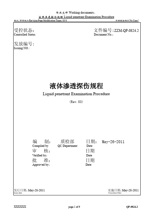
受控状态: 文件编号:ZZM-QP-0824.2 Controlled Status Document No.:发放编号:Issuing NO.:液体渗透探伤规程Liquid penetrant Examination Procedure(Rev.03)编 制: 质检部 日期: May-26-2011 Compiled by QC Department Date审 核: 日期Verified by:Date批 准: 日期Approved by:Date发行日期:May-28-2011实施日期:May-28-2011 Issue date Execution Date1.目的:依ASTM E165标准要求,结合API 6A标准、核电用《钴基SFA-5.13 ECoCr-A手工焊用焊条采购规程》(SM2-ME02-GPP-059)等等,为液体渗透检测——可视法建立检测方法、规定检测人员要求、明确产品接受准则。
Establishes the methods, personnel requirements and acceptance criteria for performing liquid penetrant examinationusing the visible methods in accordance with the requirements of API Specification 6A, Procurement specificationfor SFA-5.13 EcoCr-A Covered Electrode for SMAW (SM2-ME02-GPP-059)etc. This procedure complies with therequirements of ASTM E165.2.适用范围:本方法适用于本公司精铸件、锻件、机加工件产品的焊接/补焊及焊接(接焊、焊补、堆焊和表面硬化)件用液体渗透检测方法,检查表面组织中断:如疏松、气孔、龟裂、叠痕、冷隔、渗漏、夹渣和熔合不足(虚焊)等缺陷。
无损检测人员资格鉴定和认证
Recommended Practice No.SNT-TC-1A2016 EditionPersonnel Qualif ication and Certification in Nondestructive Testing无损检测人员资格鉴定和认证推荐性实施细则Copyright ©201 6 by The American Society for Nondestructive Testing.2016版版权归美国无损检测学会所有。
The American Society for Nondestructive Testing, Inc. (ASNT) is not responsible for the authenticity or accuracy of information herein. Published opinions and statements do not necessarily reflect the opinion of ASNT. Products or services that are advertised or mentioned do not carry the endorsement or recommendation of ASNT.在这里,美国无损检测学会不负责信息的真实性和准确性。
已经出版的意见和声明不反映ASNT 的意见。
刊登广告或提及的产品或服务没有得到ASNT的认可和推荐。
No part of this publication may be reproduced or transmitted in any form, by means electronic or mechanical including photocopying, recording or otherwise, without the expressed prior written permission of The American Society for Nondestructive Testing, Inc. 没有美国无损检测学会的明确的预先书面许可,本出版物不能以任何电子或机械的形式被复制或传递,包括复印,录制或别的方法。
SNT-TC-1A-2016-addendum+18增补
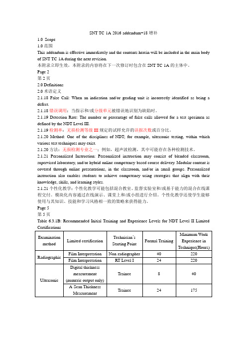
SNT-TC-1A-2016-addendum+18增补1.0Scope1.0范围This addendum is effective immediately and the contents herein will be included in the main body of SNT-TC-1A during the next revision.本附录立即生效,本附录的内容将在下一次修订时包含在SNT-TC-1A的主体中。
Page 2第2页2.0 Definitions2.0术语定义2.1.18 False Call: When an indication and/or grading unit is incorrectly identified as being a defect.2.1.18错误调用:当指示和/或分级单元被错误地识别为缺陷时。
2.1.19 Detection Rate: The number or percentage of false calls allowed for a test specimen as defined by the NDT Level III.2.1.19检测率:无损检测等级III规定的试样允许的误报次数或百分比。
2.1.20 Method: One of the disciplines of NDT; for example, ultrasonic testing, within which various test techniques may exist.2.1.20方法:无损检测专业之一;例如,超声波检测,其中可能存在各种检测技术。
2.1.21 Personalized Instruction: Personalized instruction may consist of blended classroom, supervised laboratory, and/or hybrid online competency-based course delivery. Modular content is covered through online presentations, in the classroom, and/or in small groups. Personalized instruction also enables students to achieve competency using strategies that align with their knowledge, skills, and learning styles.2.1.21个性化教学:个性化教学可能包括混合教室、监督实验室和/或基于能力的混合在线课程交付。
国外主要标准中英文名称及相关词汇表
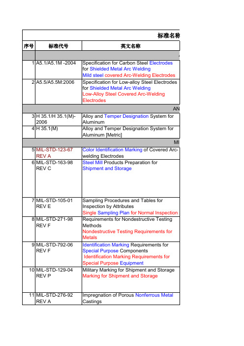
38 B18.22.1 - 1965 39 B18.24 - 2004 40 B 18.24.1 41 B18.3 - 2003
42 B 18.3 43 44 45 46 47 B18.3.1M - 1986 B 36.10 B36.10M - 2004 B36.19M - 2004 B46.1 - 2002
54 ISO 898/Ⅱ-1992
55 ISO 4775-1992
56 ISO/IEC 170252005 Rev.2 57 ISO 2178-1982
Mechanical properties of fasteners - Part 2: Nuts with specified proof load values Coarse thread Mechanical Properties of Fasteners, Part Ⅱ,Nuts with Specified Proof Loads Hexagon Nuts For High-Strength Bolting With Large Width Across Flats-Product Grade B Property Classes 8 And 10 Hexagon Nuts for High-Strength Structural Bolting with Large Width Across FlatsProduct Grade B-Property Classes 8 and 10 General requirements for the Competence of Testing and Calibration Laboratories Nonmagnetic Coatings on Magnetic Substrate--Measurement of coating Thickness--Magnetic Method SAE标准 Numbering Metals and Alloys Steel Cleanliness, Premium Aircraft-Quality Magnetic Particle Inspection Procedure Premium Aircraft Quality Steel Cleanliness Magnetic Particle Inspection Procedure Steel Cleanliness, Aircraft Quality Magnetic Particle Inspection Procedure Aircraft Quality Steel Cleanliness Magnetic Particle Inspection Procedure
工业检测型红外热像仪标准

工业检测型红外热像仪标准英文回答:Industrial Inspection Infrared Thermography Standards.Industrial inspection infrared thermography (IR) is a non-destructive testing (NDT) technique that uses an infrared camera to detect and visualize heat patterns on the surface of an object. This information can be used to identify defects, leaks, corrosion, and other problems that may not be visible to the naked eye.There are a number of different standards that govern the use of IR thermography for industrial inspection. These standards provide guidelines for the equipment, procedures, and reporting requirements that must be followed in order to ensure the accuracy and reliability of the results.Some of the most common standards for industrial inspection IR thermography include:ASTM E1417-13: Standard Practice for Infrared Imaging for Industrial Inspections.ISO 18436-1:2014: Non-Destructive Testing Infrared Thermography Part 1: General Procedures.ASNT SNT-TC-1A: Recommended Practice for Personnel Qualification and Certification in Nondestructive Testing.AWS D1.1/D1.1M:2020: Structural Welding Code Steel.These standards cover a wide range of topics, including:The equipment that must be used.The procedures that must be followed.The reporting requirements.The qualifications of the personnel who perform the inspections.By following these standards, industrial inspectors can ensure that they are using IR thermography to its full potential to identify and solve problems.中文回答:工业检测型红外热像仪标准。
ASNT购买书籍

Customer #:Dalian Kaiser Non-Destructive Testing Technology Co LtdMr Lun Li14 13 ZhongBei Bldg HuaNan Plaza No 9 9 Shandong Street Dalian, 116091CHINA Customer #: 215189Ship To:Dalian Kaiser Non-Destructive Testing Technology Co Ltd 14 13 ZhongBei Bldg HuaNan Plaza No 9 9 Shandong Street Dalian, 116091CHINA215189Bill To:Volume 2, Liquid Penetrant Testing0144Nondestructive Testing Handbook, Third Edition: Volume 4, Radiographic Testing1$181.25$181.250147Nondestructive Testing Handbook, Third Edition: Volume 7, Ultrasonic Testing1$181.25$181.250148Nondestructive Testing Handbook, Third Edition: Volume 8, Magnetic Testing1$181.25$181.251640Personnel Training Publications: Liquid Penetrant Testing Classroom Training Book1$26.50$26.501641Personnel Training Publications: Magnetic Particle Testing Classroom Training Book 1$26.50$26.501642Personnel Training Publications: Ultrasonic Testing Classroom Training Book 1$26.50$26.501644Personnel Training Publications: Radiographic Testing Classroom Training Book1$26.50$26.502026Supplement to Recommended Practice No. SNT-TC-1A (Q&A Book): Radiographic Testing Method Second Edition1$45.50$45.502027Supplement to Recommended Practice No. SNT-TC-1A (Q&A Book): Magnetic Particle Method Second Edition1$45.50$45.50Please remit wire to:JP Morgan Chase, NA Please reference the invoice # on wire. ABA # 044000037 Account # 981027205 Swift Code: CHASUS33Payable in US $ only. Prices firm for 60 days from the invoice date. Customer is responsible for all fees incurred by payment by wire transfer. Order will ship when full payment has beenreceived.PLEASE DETACH AND REMIT WITH YOUR PAYMENT#[ ] American Express[ ] Discover[ ] Visa [ ] Mastercard215189Customer #:01/18/2013Invoice Date:Invoice#:167724[ ] Funds Transfer [ ] Check Balance:Total Paid:Cardholder Name:Card #:Card Billing Address :Amount Paid: $Expiration:CCV:Customer #:Dalian Kaiser Non-Destructive Testing Technology Co LtdMr Lun Li14 13 ZhongBei Bldg HuaNan Plaza No 9 9 Shandong Street Dalian, 116091CHINA Customer #: 215189Ship To:Dalian Kaiser Non-Destructive Testing Technology Co Ltd 14 13 ZhongBei Bldg HuaNan Plaza No 9 9 Shandong Street Dalian, 116091CHINA215189Bill To:1A (Q&A Book): Ultrasonic Testing Method Second Edition2029Supplement to Recommended Practice No. SNT-TC-1A (Q&A Book): Liquid Penetrant Testing Method, Second Edition1$45.50$45.502253ASNT Level III Study Guide: Magnetic Particle Testing Method, Revised1$58.00$58.002255ASNT Level III Study Guide: Liquid Penetrant Testing Method, Second Edition1$58.00$58.002259ASNT Level III Study Guide: Radiographic Testing Method, Second Edition1$58.00$58.002261ASNT Level III Study Guide: Ultrasonic Method 1$58.00$58.006100ASNT Level II Study Guide: Magnetic Particle Testing Method, Second Edition1$40.00$40.006101ASNT Level II Study Guide: Liquid Penetrant Testing Method, Second Edition1$40.00$40.006102ASNT Level II Study Guide: Radiographic Testing Method, Third Edition1$47.00$47.006103ASNT Level II Study Guide: Ultrasonic Testing Method, Second Edition1$40.00$40.00Please remit wire to:JP Morgan Chase, NA Please reference the invoice # on wire. ABA # 044000037 Account # 981027205 Swift Code: CHASUS33Payable in US $ only. Prices firm for 60 days from the invoice date. Customer is responsible for all fees incurred by payment by wire transfer. Order will ship when full payment has beenreceived.PLEASE DETACH AND REMIT WITH YOUR PAYMENT#[ ] American Express[ ] Discover[ ] Visa [ ] Mastercard215189Customer #:01/18/2013Invoice Date:Invoice#:167724[ ] Funds Transfer [ ] Check Balance:Total Paid:Cardholder Name:Card #:Card Billing Address :Amount Paid: $Expiration:CCV:Customer #:Dalian Kaiser Non-Destructive Testing Technology Co LtdMr Lun Li14 13 ZhongBei Bldg HuaNan Plaza No 9 9 Shandong Street Dalian, 116091CHINA Customer #: 215189Ship To:Dalian Kaiser Non-Destructive Testing Technology Co Ltd 14 13 ZhongBei Bldg HuaNan Plaza No 9 9 Shandong Street Dalian, 116091CHINA215189Bill To:Please remit wire to:JP Morgan Chase, NA Please reference the invoice # on wire. ABA # 044000037 Account # 981027205 Swift Code: CHASUS33Payable in US $ only. Prices firm for 60 days from the invoice date. Customer is responsible for all fees incurred by payment by wire transfer. Order will ship when full payment has beenreceived.PLEASE DETACH AND REMIT WITH YOUR PAYMENT#[ ] American Express[ ] Discover[ ] Visa [ ] Mastercard215189Customer #:01/18/2013Invoice Date:Invoice#:167724[ ] Funds Transfer [ ] Check $1,540.36Balance:Total Paid:$1,540.36Cardholder Name:Card #:Card Billing Address :Amount Paid: $Expiration:CCV:。
ASTM E 1444 – 05 磁粉检测标准惯例
标准编号:E 1444 – 05磁粉检测标准1本标准出版编号为E 1444;紧随编号后的数字是最初出版或最后一次修订的年份。
括号里的数字标明了最后一次正式批准的年份。
上标(e)标明了自最后一次修订或再批准后的编辑改变。
本标准已被国防部门认可。
1.适用范围1.1本标准确立了磁粉检测能发现铁磁性材料表面或近表面缺陷的最低要求。
和本标准一起的操作说明 E 709 可以作为检测的一个教程。
注释1:本标准替代MIL-STD-1949.1.2磁粉检测法可以用来检测铁磁性材料表面及近表面的裂纹,折叠,夹杂,切痕和其他不连续缺陷。
磁粉检测法可用于检测原材料,毛坯,成品和半成品材料,焊缝,以及在役检测。
磁粉检测法不适用于非铁磁性材料及合金如奥氏体不锈钢。
详见附录X6 .1.3本标准的各部分可由厂商和工程行业组织之间协商决定,或由工程行业组织特别指定。
1.4本标准并不涉及所有的安全领域。
本标准使用者有责任优先考虑操作者来改善并确立恰当的安全健康标准。
2.引用标准和文献2.1下列标准和文献的部分条文通过引用形成本标准的一个部份,在下面给于注明。
2.2ASTM 标准2 :A 275/A 275M Test Method for Magnetic Particle Examination of Steel ForgingsA 456 Specification for Magnetic Particle Inspection of Large Crankshaft ForgingsD 1966 Test Methods for Foots in Raw Linseed OilE 543 Practice for Evaluating Agencies that Perform NondestructiveTestingE 709 Guide for Magnetic Particle ExaminationE 1316 Terminology for Nondestructive Examinations2.3ASNT Documents:3SNT-TC-1A Recommended Practice No. “Personnel Qualification and Certification in Nondestructive TestingANSI/ASNT CP-189 Standard for Qualification and Certification of NDT Personnel2.4 Society of Automotive Engineers (SAE)-AMS Documents:4,5AMS 2641 Magnetic Particle Inspection VehicleAMS 3040 Magnetic Particles, Nonfluorescent, Dry MethodAMS 3041 Magnetic Particles, Nonfluorescent, Wet Method, Oil Vehicle, Ready-To-UseAMS 3042 Magnetic Particles, Nonfluorescent, Wet Method, Dry PowderAMS 3043 Magnetic Particles, Nonfluorescent, Wet Method, Oil Vehicle, Aerosol PackagedAMS 3044 Magnetic Particles, Fluorescent, Wet Method, Dry PowderAMS 3045 Magnetic Particles, Fluorescent, Wet Method,Oil Vehicle,Ready-To-UseAMS 3046 Magnetic Particles, Fluorescent, Wet Method,Oil Vehicle, Aerosol Packaged5AMS 5062 Steel, Low Carbon Bars, Forgings, Tubing,Sheet, Strip, and Plate 0.25 Carbon,MaximumAMS 5355 Investment Castings AMS I-83387 Inspection Process,AS 4792 Water Conditioning Agents for Aqueous Magnetic Particle Inspection AS 5282 Tool Steel Ring Standard for Magnetic Particle InspectionAS 5371 Reference Standards Notched Shims for Magnetic Particle Inspection 2.5 Federal Standards:4,6FED-STD-313 Material Safety Data Sheets, Preparation and the Submission of FED-STD-595 Colors2.6 Military Standards:4,6MIL-STD-1907 Inspection, Liquid Penetrant and MagneticParticle Soundness Requirements for Materials, Parts, andWeldmentsMIL-STD-2175 Castings, Classification and Inspection ofA-A-59230 Fluid, Magnetic Particle Inspection, Suspension2.7 OSHA Document:729 CFR 1910.1200 Hazard Communication2.8 ANSI Document:4,8ANSI/NCSL Z 540-1 General Requirement for CalibrationLaboratories and Measuring Test Equipment2.9 ISO Document:ISO 10012-1 Quality Assurance Requirements for MeasuringEquipment92.10 AIA Document:NAS 410 Certification and Qualification of NondestructiveTest Personnel102.11 DoD Contracts—Unless otherwise specified, the editions of the documents that are DoD adopted are those listed in the issue of the DoDISS (Department of Defense Index of Specifications and Standards) cited in the solicitation.2.12 Order of Precedence—In the event of conflict between the text of this practice and the referenced documents cited herein, the text of this practice takes precedence.3.术语3.1 定义—在本标准使用的定义引自术语E 1316 中和磁粉检测有关的定义3.2本标准特殊术语的定义:3.2.1 工程行业组织—公司, 机构或其他权威的磁粉检测部门或组织。
基于美国ASME标准的磁粉检测规程

CONTENTS1.Scope2。
Qualification of NDE Personnel。
3。
Procedure4.Magnetizing Equipment and Material5。
Surface Preparation6。
Examination7.Evaluation8。
Demagnetization9。
Reexamination for repaired Area and Nonconformity Control10。
Post Cleaning11。
ReportSUSPENSION CONCENTRATION CALIBRATION RECORDMAGNETIC PARTICLE EXAMINATION INSTRUCTIONMAGNETIC PARTICLE EXAMINATION REPORT1。
Scope1.1。
This procedure is applied to detect cracks and other discontinuities on or near the surface of ferromagnetic materials, using wet magnetic particle and AC or DC yoke technique with continuous magnetization method 1.2。
This procedure is applied to welds and materials of ASME Code pressure vessels fabricated according to ASME Code Section Ⅷ Division 1。
2。
Qualification of NDE PersonnelAll personnel performing magnetic particle examination shall be qualified and certified in accordance with the requirements of HT’s Written Practice for NDE Personnel Training, Examination, Qualification and Certification based on the requirements of“SNT—TC—1A”(Current Code accepted edition)3。
UTⅡ级规程考试试题
UT Ⅱ级规程考试试题1. 按照49 CFR §178.45的规定,水压试验之后,3T钢瓶的筒体部分必须采用标准进行斜射波检测和标准进行直射波检测。
As specified in 49 CFR §178.45, any cylinder designed to the requirements for specification 3T, after the hydrostatic test, the cylindrical section of each vessel must be examined in accordance with for shear wave and for straight beam.A. ASTM E213B. ASTM E114C. ASTM E165D.ASMT E7092. 按照49 CFR §178.45的规定,制造钢瓶的材料不得有:( )As specified in 49 CFR §178.45,the material of cylinder shall be free from:A. 接缝SeamsB. 裂纹CracksC. 夹层LaminationsD. 其它有害缺陷Other injurious defectsE. 以上均是All of the above3. 按照49 CFR §178.37规定,钢瓶如果采用水淬,或者采用冷却速度超过水冷却速度的80%的其它淬火液进行淬火时,每只钢瓶必须进行检测,来查看是否存才淬火裂纹?As specified in 49 CFR §178.37, all cylinders, if water quenched or quenched with a liquid producing a cooling rate in excess of 80 percent of the cooling rate of water, must be inspected by the method to detect the presence of quenching cracks.A. 超声检测Ultrasonic testingB. 磁粉检测Magnetic testingC. 着色渗测Dye penetrant testingD. 以上之一One of the above4. 水耦合自动超声波测厚时,当水界面的第二次回波在钢界面入射信号和底面信号之间时,应如何处理:( )In immersion testing, to remove the second water reflection from between the entry surface signal and the first back reflection, you should:A. 增加重复频率Increase the repetition rateB. 降低频率Decrease the frequencyC. 降低扫描范围Decrease the sweep lengthD. 增加水距Increase the water path5. 按照DOT-E 8009规定,3AAX钢瓶应在之后,应对每个钢瓶的圆柱截面按照ASTM标准A-388-95的要求进行检测。
AMS2631B-1995(2007)__钛、钛合金棒材和坯的超声波检测
IssuedSAE Technical Standards Board Rules provide that: “This report is published by SAE to advance the state of technical and engineering sciences. The use of this report is entirely voluntary, and its applicability and suitability for any particular use, including any patent infringement arising therefrom, is the sole responsibility of the user.” SAE reviews each technical report at least every five years at which time it may be reaffirmed, revised, or cancelled. SAE invites your written comments and suggestions. Copyright © 2007 SAE InternationalAll rights reserved. No part of this publication may be reproduced, stored in a retrieval system or transmitted, in any form or by any means, electronic, mechanical, photocopying, recording, or otherwise, without the prior written permission of SAE.TO PLACE A DOCUMENT ORDER:Tel: 877-606-7323 (inside USA and Canada)Tel: 724-776-4970 (outside USA)Fax: 724-776-0790Email: CustomerService@ SAE WEB ADDRESS: h ttp:// Copyright SAE InternationalProvided by IHS under license with SAELicensee=Defense Contract Mgmt Command/5935922100AMS 2631BSAE AMS 2631B2.32.42.6ASTM Publications:Available from ASTM, 1916 Race Street, Philadelphia, PA 19103-1187.ASTM E 127 Fabricating and Checking Aluminum Alloy Ultrasonic Standard Reference Blocks ASTM E 317 Evaluating Performance Characteristics of Ultrasonic Pulse-Echo Testing SystemsWithout the Use of Electronic Measurement InstrumentsASTM E 428 Fabrication and Control of Steel Reference Blocks Used in Ultrasonic InspectionU.S. Government Publications:Available from DODSSP, Subscription Services Desk, Building 4D, 700 RobbinsAvenue,Philadelphia, PA 19111-5094.MIL-STD-410 Nondestructive Testing Personnel, Qualification and Certification (Eddy Current,Liquid Penetrant, Magnetic Particle, Radiographic and Ultrasonic)ANSI Publications:Available from American National Standards Institute, Inc., 11West 42nd Street, New York,NY 10036.ANSI B46.1 Surface TextureASNT Publications:Available from American Society for Nondestructive Testing, 1711 Arlingate Plaza,P.O. Box 28518, Columbus, OH 43228-8518.SNT-TC-1A Recommended Practice, Personnel Qualification and Certification in NondestructiveTestingATA Publications:Available from Air Transport Association, 1301 Pennsylvania Avenue, Suite 1100,Washington DC 20004-1707.ATA-105Guidelines for Training and Qualifying Personnel in Nondestructive Testing3. TECHNICAL REQUIREMENTS:3.1 Qualification:3.1 .1 Personnel: Shall be qualified and certified in accordance with MIL-STD-410. Alternate (R) procedures, i.e. ASNT-TC-1A or ATA-105, m ay be used if specified by the drawing or purchaseorder. It is the suppliers responsibility to ensure that personnel are certified and function withinthe limits of the applicable specification or procedure.-2-2.22.5Copyright SAE International--`,,``,```,,,,`,`,`,```,``,,-`-`,,`,,`,`,,`----3-Copyright SAE International--`,,``,```,,,,`,`,`,```,``,,-`-`,,`,,`,`,,`---AMS 2631B SAE AMS 2631B3.2.2 Ultrasonic Search Units: Shall be capable of transmitting and receiving ultrasonic vibrations at (R) the frequency and energy levels specified below. The frequency used shall be the highest practical ultrasonic frequency which will provide the required penetration, resolution, and signal to noise.3.2.2.1 Search Unit Dimensions and Styles: For both contact and immersion tests with either longitudinal or shear mode, the choice of transducer dimension, style, type, etc is dependenton the test and the approved test procedure. In general, for immersion testing, flat-faced orcorrected-beam transducers with diameters 3/8 through 3/4 inch (9.5 through 19.0 mm) areacceptable. Contact units with a maximum area of 1 square inch (6.5 cm 2) with 1/2 inch(12.7 mm) minimum to 1-1/8 inch (28 mm) maximum dimensions are acceptable forlongitudinal testing, while 1 square inch (6.5 cm 2) or 1 by 1/2 inch (25 by 12.7 mm) transducers are acceptable for shear testing. Use of a focused, paint brush, liquid delay,special size, or other special transducer is acceptable when agreed upon by purchaser andvendor.3.2.2.2 Shall be the highest practical frequency which will provide the penetration and resolution (R) required. Frequencies lower than 2.25 MHz for longitudinal inspections or 1.0 MHz for shearinspections shall not be used unless agreed upon by purchaser and vendor.3.2.3 Voltage Regulator: If fluctuations in line voltage cause variations exceeding ±5% in a signalwith an amplitude equal to the upper linearity limit of the instrument, a voltage regulator shall be used on the power source; this requirement does not apply to battery-powered units.3.2.43.2.4.1 Immersion Method: For inspection by the immersion method, clean tap water shall be usedas the couplant material; rust inhibitors, wetting agents, or both, may be added. The watershall be free of visible air bubbles which could interfere with the ultrasonic test.3.2.4.2 Contact Method: For inspection by the contact method, SAE 30 motor oil in accordance withSAE J300 or cellulose gum shall be used as the couplant material. Other types of couplantmaterials that have been proven acceptable for a particular type of test may be used if agreed upon by purchaser and vendor. Chloroprene rubber sheet or similar materials may be usedbetween the transducer and the product being tested to prevent excessive transducer wearprovided adequate compensation for its use is made.3.2.5 Longitudinal Reference Standards: Shall be fabricated from AMS 4928 titanium alloy or fromother titanium alloy acoustically similar to the alloy to be tested. The procedures established in ASTM E 127 and ASTM E 428 are recommended for manufacturing ultrasonic reference blocks for straight beam testing.-4-Couplant:Copyright SAE International Provided by IHS under license with SAE Licensee=Defense Contract Mgmt Command/5935922100--`,,``,```,,,,`,`,`,```,``,,-`-`,,`,,`,`,,`----5-Copyright SAE InternationalProvided by IHS under license with SAELicensee=Defense Contract Mgmt Command/5935922100-6-Copyright SAE InternationalProvided by IHS under license with SAELicensee=Defense Contract Mgmt Command/5935922100AMS 2631B SAE AMS 2631B 3.4.2Calibration Check: To ensure valid results, a calibration check shall be made prior to the test ofeach part configuration or start of each shift of operation and at the completion of each test or shift, as appropriate. Any change in equipment operation that requires a recalibration of thetest system shall require retesting of all product or parts tested since the previous calibration. 3.5 General Scanning Procedure:3.5.1 3.5.2 3.5.4Calibration for determination of loss in the back reflection pattern shall be performed on parallel surfaces of the product being tested. The back reflection pattern from the full material thickness section of the test block at the scanning sensitivity shall be observed.If the back reflection pattern from the product being tested averages a variation of more than ±50% from that recorded from the test block, testing shall be stopped until corrective action is taken.The permissible background noise shall not exceed 50% of the response height from the reference standard of the same alloy as the product being tested. Greater background noise levels may be permitted by purchaser or lesser background noise levels may be specified.Whenever possible, a dynamic alarm check shall be made to determine the operational scanning speeds, pulse repetition rates, and index increments, and to ensure that the alarm system is capable of detecting all rejectionable defects at these operating conditions.If a dynamic alarm check cannot be made or if alarms cannot be used, the operational parameters shall be as follows:3.5.4.1Pulse repetition rate should be a minimum of 600 pulses per second (600 PPS). The exact(R)rate used shall be based on the beam diameter and surface speed.3.5.4.2For manual scanning without alarm systems, a scanning speed not greater than5.0 inches(127 mm) per second is recommended.3.5.4.3For alarm systems with or without automatic scanning, a scanning speed not greater than(R)20 inches (508 mm) per second is recommended. The exact speed shall be based on the beam diameter and repetition rate.3.5.5When the alarm system is used during testing, it shall be set at the equivalent of “Hold” or“Manual Reset”.3.5.6The instrument control settings and test parameters established during calibration shall not bechanged during testing of the product. The pulse length and reject control shall be set at theminimum that will afford the proper resolution without affecting acceptable linearity.3.5.7Distance Amplitude Correction: Electronic distance amplitude correction is recommended;however, distance amplitude curves plotted on the screen face (Cathode Ray Tube) usingdistance amplitude calibration blocks may be used if the minimum pip height complies with 3.4.Testing using the highest sensitivity from the distance amplitude calibration blocks andevaluating to the proper metal travels is also permitted provided noise levels do not obscurerequired information.-7-3.5.3Copyright SAE International--`,,``,```,,,,`,`,`,```,``,,-`-`,,`,,`,`,,`---AMS 2631B SAE AMS 2631B3.5.8 Zone testing may be used with separate calibrations and/or transducers for each zone. (R)3.6 3.6.Immersion Testing:1Longitudinal (Straight) Beam Testing: The sound beam entry angle shall be adjusted until the sound beam is perpendicular to the test surface. Where appropriate, the maximum signal amplitude from the entry surface may be used to determine this condition. Where notappropriate (e.g., a highly-focused search unit), an alternate procedure such as multiple reflections may be used. During testing, the angle established shall not vary more than±2degrees.3.6.23.6.33.6.4 (R)Angle Beam Testing: Products may be inspected with both longitudinal and shear wave motions at preselected angles. Once established, the surface entry angle shall not vary more than ±2 degrees.Water Travel: The water travel distance shall be the optimum for the transducer and the metal travels encountered during testing. The water travel distance for testing shall be within±0.25 inch (±6.4 mm) of that used for calibration.The maximum indexing increment used in scanning a product shall be 70% of the effective beam diameter. The effective beam diameter is determined by recording of the total traverse distance at the appropriate gain settings across the nearest hole in the test block through which not less than 50% signal amplitude is displayed.3.7 Contact Testing:3.7.1 Straight Beam Testing: Visual inspection of the search unit shall be made to verify that thewear face surface is intact. Periodic visual inspections shall be made during tests to ensurethat the search unit facing has not degraded. Any cracking, chipping, break-up, or uneven wear conditions shall disqualify the search unit and the test.3.7.2 Angle Beam Testing: Angle beam entry and testing mode shall be established as part of thetest procedure.3.7.3 Indexing: Indexing increments used in scanning a product shall be not greater than one-halfthe transducer diameter or the effective beam diameter, determined in accordance with 3.6.4,whichever is less. When practical, transducer indexing shall be controlled by a mechanicalsystem.3.8 Surface Area of Product to be Scanned:3.8.1 Bars and Forging Stock:3.8.1 .1Rounds, All Diameters: The entire circumference.3.8.1.2Flat-Faced Product 2 to 5 Inches (51 to 127 mm), Inclusive, in Cross Section: Test alladjacent faces representing 50% of the periphery.-8-Copyright SAE InternationalProvided by IHS under license with SAE Licensee=Defense Contract Mgmt Command/5935922100 --` , , ` ` , ` ` ` , , , , ` , ` , ` , ` ` ` , ` ` , , -` -` , , ` , , ` , ` , , ` ----9-Copyright SAE InternationalAMS 2631B SAE AMS 2631B4.2Disposition:4.2.1Product exhibiting evaluated indications not in excess of established standards may beaccepted without remedial operations.4.2.2Product exhibiting evaluated indications in excess of established standards but in a locationwhich will be removed during manufacturing operations may be approved by authorizedpersonnel for acceptance and shall be reported to purchaser.4.2.3Product containing discontinuities in excess of established standards and not covered by 4.2.2shall be rejected.4.3Records:The testing source shall prepare and maintain on file, for the time specified by purchaser, recordsof the requirements and techniques for each size and configuration of product. When requestedby purchaser, these records shall be made available for inspection.5. PREPARATION FOR DELIVERY:Not applicable.6. ACKNOWLEDGMENT:A vendor shall mention this specification number and its revision letter in all quotations and whenacknowledging purchase orders.7. REJECTIONS:Product inspected in accordance with this specification and not meeting specified requirements, or modifications authorized by purchaser, will be subject to rejection.8.NOTES:8.1The (R) symbol is for the convenience of the user in locating areas where technical revisions, noteditorial changes, have been made to the previous issue of this specification.If the symbol isnext to the specification title, it indicates a complete revision of the specification.--`,,``,```,,,,`,`,`,```,``,,-`-`,,`,,`,`,,`----10-Copyright SAE InternationalProvided by IHS under license with SAE Licensee=Defense Contract Mgmt Command/5935922100AMS 2631B SAE AMS 2631B 8.2Test Conditions:It is essential that thorough understanding be developed between purchaser and vendorregarding interpretation of the results of inspection and how they shall be recorded and reported.Ultrasonic testing is so comprehensive that it is necessary that all interested parties fullyrecognize that indications may appear which do not reflect conditions detrimental to use of the product. Agreement between purchaser and vendor should be established in advance on the following:Surface finishInternal structureLocation and extent of areas to be scannedSize of transducer and type of search unitTest frequencyType and grade of couplantMethod of calibration of equipment8.3Local grinding depressions will cause sonic wave attenuation, loss of back reflection, and inabilityto locally meet standards.8.4 8.5Definitions of terms used in AMS are presented in ARP1917.Dimensions in inch/pound units are primary; dimensions in SI units are shown as the approximate equivalents of the primary units and are presented only for information.8.6Processes meeting the requirements of this specification have been classified under FederalStandardization Area Symbol “NDTI”.PREPARED UNDER THE JURISDICTION OF AMS COMMITTEE“K”-11-Copyright SAE InternationalProvided by IHS under license with SAE Licensee=Defense Contract Mgmt Command/5935922100Not for Resale, 07/02/2007 17:27:41 MDTNo reproduction or networking permitted without license from IHS--`,,``,```,,,,`,`,`,```,``,,-`-`,,`,,`,`,,`---Note 1:Note 2: (R) Note 3:Thickness (T)may be increased to accommodate larger search units provided the depth of hole A is T/2 -0.12 (3.0) and the depth of hole B is T/2 +0.12 (3.0).Dimensions are in inches (millimeters) except as noted.All surfaces 63 µm)FIGURE 1- Calibration Block Use for Evaluating Vertical Linearity- 12 -√(1.6Copyright SAE InternationalProvided by IHS under license with SAE Licensee=Defense Contract Mgmt Command/5935922100Not for Resale, 07/02/2007 17:27:41 MDTNo reproduction or networking permitted without license from IHSVERTICAL LINEARITY PLOTSFIGURE 2FIGURE 3-13 -Copyright SAE InternationalProvided by IHS under license with SAE Licensee=Defense Contract Mgmt Command/5935922100No reproduction or networking permitted without license from IHSNot for Resale, 07/02/2007 17:27:41 MDT主营业务范围:ASTM、NAS、NASM、MIL、ISO、EN、DIN等技术标准翻译;技术资料翻译。
(质量管理手册)质量控制手册
(质量管理手册)质量控制手册量控制手册用于按照ASME第VIII卷第1分册进行车间生产的压力容器和部件QUALITY CONTROL MANUAL FOR SHOP CONSTRUCTION OF PRESSURE VESSELS AND PARTS INACCORDANCE WITH ASME CODE SECTION VIII, DIVISION 1生效日期:2013 年3 月20日EFFECTIVE DATE: Mar. 20 , 2013上海朗森热工设备有限公司Shanghai Langsen Thermal Equipment Co., Ltd 上海市嘉定工业区朱桥世盛路760号,邮编201815 No.760,Shisheng Road, Jiading Industrial Zone, Jiading District,Shanghai 201815,P.R.China质量控制手册QUALITY CONTROL MANUAL 章号Section No. A 修订号Rev. No. 0总经理授权声明STATEMENT OF AUTHORITY 共1页Page第1页1 of 1of the Quality Control System to me.Any conflict between the QualityManager and other Managers shall beresolved by me, considering completely theASME Code requirements, designjustification and this Quality ControlManual.The Chinese translation of this QualityControl Manual may be used forimplementation of the Quality ControlSystem. However, in event of a disputeregarding differences in interpretationbetween the English text and Chinesetranslation of Manual, the English text shalltake precedence.General Manager:__________________________Date:______ _______质量控制手册QUALITY CONTROL MANUAL 章号Section No. B 修订号Rev. No. 0总目录TABLE OF CONTENTS 共1页Page第1页1 of 1质量控制手册QUALITY CONTROL MANUAL 章号Section No. C 修订号Rev. No. 0定义和缩略语DEFINITIONS AND ABBREVIATIONS 共3页Page第1页1 of 3定义规范ASME锅炉和压力容器规范第VIII卷第1分册及规范的有关卷本。
无损检测工艺规程(超 声 波 检 验)
0
Frequency 2.5MHz 2.5MHz 2.5MShantou, China Shantou, China Shantou, China 2.5P 8x12 探头 2.5P 8x12
折射 角 (β) 450 560 630 680
频率 2.5MHz 2.5MHz 2.5MHz 2.5MHz
制造 单位 汕头超声 仪器厂 汕头超声 仪器厂 汕头超声 仪器厂 汕头超声 仪器厂
680
Shantou, China 2.5P 8x12 2.5P 8x12
The range of angle is recommended as following:
0 0
K 值 (tgβ) 3.0-2.0 2.5-1.5 2.0-1.0
630-450
630-450
4.3 Frequency Generally, the frequency of 2.5MHz shall be used. For the thinner plate, 5MHz may be used. 4.4 Screen Height linearity The ultrasonic instrument shall provide linear vertical presentation within±5% of the full screen height for 20% to 80 of the calibrated screen height (base line to maximum calibrated screen point(s)). The procedure for evaluating screen height linearity is provided in Appendix Ⅰof ASME Code Sect. V Sub. A Article 5 and shall be performed at the beginning of each period of extended use (or every 3 months, whichever is less). 4.5 Amplitude Control Linearity The ultrasonic instrument shall utilize an amplitude control accurate over its useful range to ±20% of the nominal amplitude ratio, to allow measurement of indications beyond the linear range of the vertical display on the screen. The procedure for evaluating amplitude control linearity is given in ASME Sect V. Art .5. Appendix Ⅱand shall be performed at the beginning of each period of extended use(or every 3 months, whichever is less). 4.6 Checking and Calibration of Equipment The proper functioning of the examination equipment shall be checked and the equipment shall be calibrated by the use of the calibration standard at the beginning and end of each examination., when examination personnel are changed, and at any time that malfunctioning is suspected as a minimum. If during any check it is determined that the testing equipment is not functioning properly, all of the product that has been tested since the last valid equipment calibration shall be reexamined. 5. CALIBRATION 5.1 Basic Calibration Block Configuration
snt 1991 检验规程

snt 1991 检验规程English Answer:Sampling Procedure & Acceptance Criteria for SNT-TC-1A.The SNT-TC-1A (Recommended Practice for Personnel Qualification and Certification in Non-Destructive Testing) standard provides a comprehensive framework for the qualification and certification of NDT personnel. Among its many provisions, SNT-TC-1A establishes specific requirements for sampling procedures and acceptancecriteria used in NDT examinations.Sampling Procedures.The selection of an appropriate sampling procedure is crucial for ensuring the reliability and effectiveness of NDT examinations. SNT-TC-1A recognizes that the specific sampling procedure employed should be tailored to the type of examination being performed, the materials beingexamined, and the applicable code or standard.The standard categorizes sampling procedures into three primary types:Statistical sampling utilizes probability theory to select a representative sample of the population being inspected. This approach provides a quantifiable estimate of the overall defect rate.Random sampling selects samples in a random manner without regard to any specific distribution pattern. This method is suitable for situations where the defect distribution is unknown or unpredictable.Systematic sampling involves selecting samples at regular intervals or locations throughout the population. This approach ensures a uniform coverage of the area being inspected.The appropriate sampling procedure should be chosen based on the specific requirements of the examination,considering factors such as the criticality of the component, the expected defect rate, and the available resources.Acceptance Criteria.Acceptance criteria define the limits of acceptability for NDT examination results. These criteria establish the threshold for determining whether a component or material is acceptable for its intended use. The acceptance criteria should be clearly defined and agreed upon by all relevant parties prior to the commencement of the examination.SNT-TC-1A outlines two primary types of acceptance criteria:Attribute acceptance criteria specify the maximum number of defects or the percentage of defective items that are allowed within a given sample. This approach issuitable for situations where the presence or absence of defects is the primary concern.Variable acceptance criteria establish specific limits for the measured values of the NDT parameters. This approach is used when the magnitude or severity of defects is of primary importance.The choice of acceptance criteria should be based on the specific requirements of the examination, considering factors such as the consequences of failure, the safety margins, and the reliability of the NDT method.Implementation and Verification.The effective implementation of sampling procedures and acceptance criteria is essential for maintaining thequality and consistency of NDT examinations. SNT-TC-1A emphasizes the importance of establishing written procedures that clearly outline the specific requirements for each examination. These procedures should be reviewed and approved by qualified personnel to ensure their accuracy and completeness.Regular verification of the sampling procedures andacceptance criteria is also crucial. This may involve witness audits, proficiency testing, or other methods to assess the consistency and reliability of the NDT examinations. By conducting regular verification, organizations can ensure that their NDT programs are meeting the intended objectives and providing the necessary level of quality assurance.Conclusion.The sampling procedures and acceptance criteriaoutlined in SNT-TC-1A provide a vital framework for ensuring the reliability and effectiveness of NDT examinations. By following the guidelines established in the standard, organizations can establish and implement robust NDT programs that enhance product quality, ensure safety, and meet regulatory requirements.中文回答:SNT 1991 检测规程。
ASNT(SNT-TC-1A)

Limited Certification
!
Nondestructive test methods may be further subdivided into limited disciplines or techniques to meet specific employers needs. The intent is that this is a full certification to a limited scope.
!
!
!
Functions of Methods
!
Amount of Formal Training Amount of Work Experience Number of Exam Questions Recommended Training Outlines
!
!
!
Approval Process
Film Interpretation ! Digital Radioscopy ! Digital Thickness Testing ! A-Scan Thickness
!
!
Direct – Remote Visual
!
Visual Testing Method – committee added training guidelines for the use of remote visual equipment. Training outlines, Hours of Formal Training and Work Experience requirements were added.
!
NDT Method - Technique
!
NDT Method – The basic theory used to generate an indication which can include several different methodologies to detect the response. Technique – A specific application of a method used to detect and evaluate indications generated by a method.
Summary of Changes in SNT-TC-1A 2011
5
6.0 Education, Training, and Experience Requirements for Initial Qualification
• 6.3.1 NDT Levels I and II • Table 6.3.1 A lists the recommended training and experience hours
1
SNT-TC-1A 2011
Joe Mackin
2
1.0 Scope
• 1.4
It is recognized that these guidelines may not be appropriate for certain employers’ circumstances and/or applications. In developing a written practice as required in Section 5, the employer should review the detailed recommendations presented herein and modify them, as necessary, to meet particular needs. Such modification may alter but shall not eliminate basic provisions of the program such as training, experience, testing and recertification. Supporting technical rationale for modification of detailed recommendations should be provided in an Annex to the written practice.
磁粉检验方法和验收标准
CONTENT目录1.0 SCOPE范围 (3)2.0 REFERENCE STANDARD 参考标准 (3)3.0 PERSONNEL QUALIFICATION 人员资质 (3)4.0 EXTENT OF NDT NDT 范围 (3)5.0 TIMING OF NDT NDT检验时间 (4)6.0 TESTING PROCEDURE 检测程序 (4)7.0 REPORT FORM 报告格式 (10)1.0 SCOPE 范围This procedure covers the methods, techniques and acceptance criteria for MagneticⅡ. Particle Inspection of LUFENG 13-2 OILFIELD DEVELOPMENT PHASE PROJECT本检验程序包含了LUFENG 13-2 OILFIELD DEVELOPMENT(PHSAE-2)项目磁粉检验的检验方法、检验工艺和验收标准。
2.0 REFERENCE STANDARD 参考标准• Owner’s Specification• AWS D1.1-2006 Structural Welding code –Steel 钢结构焊接规范• ASME V 2007• ASMEVIII 2007• ASTM E 7093.0 PERSONNEL QUALIFICATION 人员资质Personnel performing the NDT testing shall be qualified and certified to NDT Level II in accordance with the requirements of SNT-TC-1A recommended practice and approved by NDT Level-III (COOEC) or equivalent qualifications approved by OWNER.所有从事无损检验工作的人员均应按照SNT-TC-1A推荐作法或等同标准取得II级资质证书,并由COOEC NDT III 级人员批准或经过业主的批准。
4序3 术语和缩略语

1) ASME:The American Society of Mechanical Engineers美国机械工程师协会。
2) Authorized Inspector (AI): An Authorized Inspector is a person holding a valid National Board Commission with the “A” or “A R”endorsement and regularly employed by an Authorized Inspection Agency.Authorized Inspector (AI):授权检验师,他持有美国国家锅炉压力容器检验师协会颁发的有效委任A或A R卡(Commission Card),并由授权检验机构正式雇佣。
3) Authorized Inspection Agency (AIA) of Record: The AIA that the JSSN must have in force at all times an inspection contract or agreement with, and shall be identified on the application for a new issuance or renewal of Certificates of Authorization.Authorized Inspection Agency (AIA) of Record:与JSSN公司在取换证时签定了有效检验合同的授权检验机构。
4) CC: Certificate of Compliance符合证明5) Code (ASME Code):The ASME Boiler and Pressure Vessel Code Section I, Section VIII Division 1, ASME B31.1 and other referenced Code Sections or StandardsASME锅炉与压力容器规范第I卷、第VIII卷第1册、ASME B31.1 及其引用的其它规范卷册或标准。
ASME无损检测人员资格鉴定和认证
ASME 无损检测人员资格鉴定和认证Written Practice for Qualification and Certification of NDE Personnel1 Scope1.1 This written practice provides guideline for the qualification and certification of NDE personnel who are engaged in ASME Code products manufacturing.1.2 This practice shall be in compliance with the requirements of SNT-TC-1A (current Code accepted edition).2. Definitions2.1 Terms included in this practice are defined as follows:1) Qualification: Demonstrated skill, demonstrated knowledge, documented training and documented experience required for personnel to properly perform the duties of a specific job.2) Certification:Written testimony of qualification.3) Training: The organized program developed to impart the knowledge and skills necessary for qualification.4) Experience: Work activities accomplished in a specific NDE method under the direction of qualified supervision including the performance of the NDE method and corresponding working scope but not including time spent in organized training programs.5) Certificate: Certified document.3. Nondestructive Testing MethodsQualification and certification of NDE personnel in accordance with this practice is applicable to the following methods:1) Radiographic Testing (RT)2) Ultrasonic Testing (UT)3) Liquid Penetration Testing (PT)4) Magnetic Particle Testing (MT)4. Levels of Qualification4.1 There are three (3) basic Levels of qualification for NDE individuals in accordance withSNT-TC-1A(current Code accepted edition).While in the process of being qualified and certified, an individual shall be considered a trainee. A trainee shall work with a certified individual and shall not independently conduct, interpret, evaluate, or report the results of any NDE.4.3 The three basic Levels of qualification are as follows:(1) NDE Level I: An NDE Level I individual shall be qualified to properly perform specific calibrations and evaluations for acceptanceor rejection determinations according to written instructions and to record results. The NDE Level I individual shall follow the necessary in structi on or supervisi on of a certified NDE Level n or level 川in dividual.(2) NDE Level II: An NDE Level II individual shall be qualified to set up and calibrate equipment and to interpret and evaluate results with respect to applicable codes, standards, and specifications. The NDE Level II shall be thoroughly familiar with thescope and limitations of the methods for which qualified and shall exercise assigned responsibility for on-the-job training and guidance of trainees and NDE Level I personnel. The NDE Level II shall be able to prepare the instructions, organize NDEexamination and report the results of NDE. (3) NDE Level III: An NDE Level III individual shall be capable of establishing techniques and procedures, interpreting Code, standards, specifications and procedures and designating the particular NDE methods, techniques and procedures to be used. The NDE Level III individual shall be responsible for the NDE operations for which qualified and assigned and be capable of interpreting and evaluating results in terms of existing Code, standards and specifications. The NDE Level III shall have sufficient practical background in applicable materials, fabrication, and product tech no logy to establish tech niq ues and to assist in establish ing accepta nee criteria in case of other criteria available. The NDE Level III shall have gen eral familiarity with other appropriate NDE methods as dem on strated by the ASNT Level III Basic exam in ati on or other means. The NDE Level III, in the methods in which certified, shall be capable of training and examining NDE Level Iand II personnel for certification in those methods.5. Education, Training and Experience Requirements for Initial Qualification5.1 Personnel applying for certification in NDE shall have sufficient education, training and experience to ensure to understand the principle and operation methods of the certification for which they are appl ying. 5.2 Prior to the establishment of this written practice those whose training term and experience are equivale nt to that of level, I, II, III pers onnel and are of verified may be con sidered of satisfying the criteria of Par. 5.3. In con siderati on for certificatio n, a can didate shall satisfy one of the followi ng criteria for the applicable NDE Level:5.3.1 NDE Level I and IITable 1 lists the training and experience factors required for initial qualification of Level I and Level II in dividuals.Notes:(1) . For Level II certificati on, the experie nce shall c on sist of time at Level I or equivale nt. If a pers on is being qualified directly to Level II with no time at Level I, the required experience shall consist of the sum of the times required for Level I and Level II and the required training shall con sist of the sum of the hours required for Level I and Level II.(2) . I nitial experie nce may be gained simulta neously in two or more methods if the can didate spends a minimum of 25% of his work time on each method for which certification is sought, and the rema in der of the work time claimed as experie nce is spe nt in NDE-related activities defined in the ABC S written practice. 5.3.2 NDE Level III(1) Have graduated from a minimum four-year college or university curriculum with a degreein engineering or science, plus one year ' s experience in NDE in an assignment comparable to that of an NDE Level II in the applicable test methods. or;(2) Have completed with passing grades at least two years of engineering or science study at a university, college, or technical school, plus two year ' s experience in NDE in an assignme least comparable to that of NDE Level II in the applicable NDE methods. or;Have four year' s experience in NDE in an assignment at least comparable to that of an NDE Level II in the applicable NDE methods.6. Trai ning Programs6.1 Personnel applying for initial certification shall receive sufficient organized training to become thoroughly familiar with the principles and practices of the specified NDE method related to the level of certification desired and applicable to the processes to be used and the products to be exam in ed.6.2 The trai ning program shall i nclude sufficie nt exam in ati ons to assure that the n ecessary in formatio n has bee n comprehe nded.6.3 ASNT recommended training course outlines for NDE Level I and II personnel are used as refere nee materials for this writte n practice.7. Exami natio ns7.1 Adm ini strati on and Grad ingNDE Level III or his desig nated represe ntative shall be resp on sible for the adm ini strati on and grad ing of exam in ati ons.7.2 Visio n Exam in ati ons1) The exam in ati on shall assure n atural or corrected n ear-dista nee acuity in at least one eye such that the applica nt is capable of read ing a minimum of Jaeger 2, or equivale nt type and size letter at a dista nee of not less tha n 305 mm on a sta ndard Jaeger test chart.2) The exam in atio n shall dem on strate the capability of disti nguish ing and differe ntiat ing con trast among colors or shades of gray used in the method.3) The visi on exam in ati ons shall be con ducted annu ally.4) Exam in ati on results shall be kept on file duri ng the period of certificatio n.For Level I and II pers onn el, a composite grade shall be determ ined by simpleaveragi ng of the results of the gen eral, specific and practical exam in ati ons described below.7.3.1 Ge neral Exami nation (Writte n)1) The gen eral exam in ati ons shall address the basic prin ciples of the applicable method.2) In prepari ng the exam in ati ons, the Chief Exam iner (Level III) or his desig nated represe ntative shall select or devise appropriate questi ons accord ing to the applicable method and the degree required by this written practice.The minimum number of questions are as follows:7.3.2 Specific Exam in ati ons (Writte n)1) The specific exam in ati on shall address the equipme nt, operati ng procedures and NDE tech niq ues that the in dividual may encoun ter duri ng specific assig nments to the degree required by this writte n practice.2) The specific exam in atio n shall also cover the specificati ons or codes and accepta nee criteria used in NDE procedures.The minimum number of questions are as follows:1) Proficie ncy shall be dem on strated in perform ing (for level n select ing and perform ing) the applicable NDE on one or more samples approved by the NDE Level III and in evaluating the results to the degree of responsibility as described in this written practice.2) Prior to examination, the Chief Examiner (Level III) or his designated representative shall prepare a checklist of at least ten (10) different checkpoints requiring an understanding of NDE parameters and the company'sprocedural requirements shall be included in this practical examination.3) The candidate shall demonstrate skillful operation of the necessary NDE equipment, record, and analyze the resultant information to the degree required.4) At least one selected specimen shall be tested and the results of the NDE shall be analyzed by the candidate.5) The description of the specimen, the NDE procedure, including check points, and the resultsof the examination shall be documented.7.4For Level III personnel, the composite grade shall be determined by simple averaging of the results of the basic, method and specific examinations described below.7.4.1 Basic Examination (required only once when more than one method examination is taken).The minimum number of questionsis as follows:1) Fifteen (15) questions relating to understanding the SNT-TC-1A document.2) Twenty (20) questions relative to applicable materials, fabrication, and product technology. Twenty (20) questions which are similar to or selected from other NDE Level II questions.7.4.2 Method Examination (for each method)1) Thirty (30) questions relating to fundamentals and principles, which are similar to or selected from published ASNT Level III questions for each method. and2) Fifteen (15) questions relating to application and establishment of techniques and procedures which are similar to or selected from published ASNT Level III questions for each method. and Twenty (20) questions relating to capability for interpreting Code, standards, and technical specifications for the method.7.4.3Specific Examination (for each method)1) Twenty (20) questions relating to technical specifications, equipments, techniques, and procedures applicable to the ABC 's products and methods employed and to the administration of the ABC 'S written practice.2) The QAD Manager may delete the specific examination described in Par 7.4.3 1) if the candidate has a valid ASNT NDE Level III or ACCP Professional Level III certificate in the method and if documented evidence of experience exists including the preparation of NDE procedures according to code, standards, or specifications and the evaluation of test results.7.4.4 A valid endorsement on an ASNT NDE Level III or ACCP Professional Level III certificate fulfills the examination criteria described in par 7.4.1 and 7.4.2 for each applicable NDE method.7.5 All Level 1,11 and 川writte n exam in ati ons shall be closed-book except that n ecessary data, such as graphs, tables, specifications, procedures, Code, etc. may be provided with or in the examination. All questions used for Level I and II examinations shall be approved by the responsible Level III.7.6 Grading1)The NDE Level III shall be responsible for the examination and actual grading of NDE LevelI , II and other level III .For all Levels, the examinations administered for qualification shall result in a passing composite grade of at least 80%, with no individual examination having a passing grade less than 70%.7.7 Re-examinationThose failing to attain the required grades must wait at least 30 days or show the evidence of recei ving suitable additi onal trai ning as determ ined by the NDE chief Exam iner (NDE Level 川) before re-examination.8. Certification8.1 The QAD Manager shall be responsible for certify the certificate of all Levels of NDE personnel.8.2 The examination records and evaluation reference shall be archived by QAD.8.3 The qualification records of the certified individuals shall include the following:(1) Name of certified individual.(2) Level of certification and NDE method.(3) Educational background and experience of certified individuals.(4) Statement indicating satisfactory completion of training in accordance with this written practice.(5) Results of the vision examination described in paragraph 7.2 for the current certification period.(6) Current examination copy(ies) or evidence of successful completion of the examinations.(7) Other suitable evidence of satisfactory qualifications when such qualifications are used in lieu of the specific examinations described in paragraph 7.4.3 2).(8) Composite grade(s) or suitable evidence of grades.(9) Dates of certification or re-certification and the dates of assignments to NDE.8.4 Re-certification8.4.1All Levels of NDE personnel shall be re-certified periodically in accordance with one of the following criteria:(1) Evidence of continuing satisfactory performance.(2) Re-examination in those portions of the examinations in paragraph 7 deemed necessary by the NDE Level III.8.4.2 NDE personnel may be re-examined at any time by the QAD Manager, NDE Level III or Authorized Inspector and have their certifications extended or revoked.8.4.3 All Levels of NDE personnel must be re-examined and re-certified if they do not work in the method in which they are certified for 6 months or more.8.4.4 Maximum re-certification intervals are:(1) Level I and II: 3 years(2) Level III:5 years9 Termination9.1 The certificate shall be deemed revoked when he is not engaged in NDE job.9.2 The certificate of NDE individual of any Level shall be deemed revoked when the employment is terminated.。
ASTM材料与实验标准.E215
Designation:E215–98(Reapproved2004)e1Standard Practice forStandardizing Equipment for Electromagnetic Examination of Seamless Aluminum-Alloy Tube1This standard is issued under thefixed designation E215;the number immediately following the designation indicates the year of original adoption or,in the case of revision,the year of last revision.A number in parentheses indicates the year of last reapproval.A superscript epsilon(e)indicates an editorial change since the last revision or reapproval.This specification has been approved for use by agencies of the Department of Defense.e1N OTE—Reapproved with editorial changes throughout in January2004.1.Scope1.1This practice2is intended as a guide for standardizing eddy-current equipment employed in the examination of seam-less aluminum-alloy tube.Artificial discontinuities consisting offlat-bottomed or through holes,or both,are employed as the means of standardizing the eddy-current system.General requirements for eddy-current examination procedures are included.1.2Procedures for fabrication of reference standards are given in Appendixes X1.1and X2.1.1.3This practice is intended for the examination of tubular products having nominal diameters up to4in.[101.6mm]and wall thicknesses up to the standard depth of penetration(SDP) of eddy currents for the particular alloy(conductivity)being examined and the examination frequency being used.N OTE1—This practice may also be used for larger diameters or heavier walls up to the effective depth of penetration(EDP)of eddy currents as specified by the using party or parties.1.4The values stated in inch-pound units are to be regarded as the standard.1.5This practice does not establish acceptance criteria. They must be established by the using party or parties.1.6This standard does not purport to address all of the safety problems,if any,associated with its use.It is the responsibility of the user of this standard to establish appro-priate safety and health practices and determine the applica-bility of regulatory limitations prior to use.2.Referenced Documents2.1ASTM Standards:3E543Practice for Agencies Performing Nondestructive TestingE1316Terminology for Nondestructive Examinations2.2Federal Standard:Fed Std.No.245D Tolerance for Aluminum Alloy and Magnesium Alloy Wrought Products42.3Other Documents:SNT-TC-1A Recommended Practice for Personnel Qualifi-cation and Certification in Nondestructive Testing5 ANSI/ASNT-CP-189ASNT Standard for Qualification and Certification of Nondestructive Testing Personnel5NAS-410NAS Certification and Qualification of Nonde-structive Personnel(Quality Assurance Committee)63.Terminology3.1Standard terminology relating to electromagnetic ex-amination may be found in Terminology E1316,Section C, Electromagnetic Testing.4.Significance and Use4.1The examination is performed by passing the tube lengthwise through or near an eddy current sensor energized with alternating current of one or more frequencies.The electrical impedance of the eddy current sensor is modified by the proximity of the tube.The extent of this modification is determined by the distance between the eddy current sensor and the tube,the dimensions,and electrical conductivity of the1This practice is under the jurisdiction of ASTM Committee E07on Nonde-structive Testing and is the direct responsibility of Subcommittee E07.07on Electromagnetic Methods.Current edition approved January1,2004.Published February2004.Originally approved st previous edition approved in1998as E215-98.2For ASME Boiler and Pressure Vessel Code applications see related Practice SE-215in the Code.3For referenced ASTM standards,visit the ASTM website,,or contact ASTM Customer Service at service@.For Annual Book of ASTM Standards volume information,refer to the standard’s Document Summary page on the ASTM website.4Available from Standardization Documents Order Desk,Bldg.4Section D,700 Robbins Ave.,Philadelphia,PA19111-5094,Attn:NPODS.5Available from The American Society for Nondestructive Testing(ASNT),P.O.Box28518,1711Arlingate Ln.,Columbus,OH43228-0518.6Available from Aerospace Industries Association of America,Inc.,1250Eye Street,N.W.,Washington,DC20005.1Copyright©ASTM International,100Barr Harbor Drive,PO Box C700,West Conshohocken,PA19428-2959,United States.tube.The presence of metallurgical or mechanical discontinui-ties in the tube will alter the apparent impedance of the eddy current sensor.During passage of the tube,the changes in eddy current sensor characteristics caused by localized differences in the tube produce electrical signals which are amplified and modified to actuate either an audio or visual signalling device or a mechanical marker to indicate the position of discontinui-ties in the tube length.Signals can be produced by disconti-nuities located either on the external or internal surface of the tube or by discontinuities totally contained within the tube wall.4.2The depth of penetration of eddy currents in the tube wall is influenced by the conductivity(alloy)of the material being examined and the excitation frequency employed.As defined by the standard depth of penetration equation,the eddy-current penetration depth is inversely related to conduc-tivity and excitation frequency(Note2).Beyond one standard depth of penetration(SDP),the capacity to detect discontinui-ties by eddy currents is reduced.Electromagnetic examination of seamless aluminum alloy tube is most effective when the wall thickness does not exceed the SDP or in heavier tube walls when discontinuities of interest are within one SDP.The limit for detecting metallurgical or mechanical discontinuities by way of conventional eddy current sensors is generally accepted to be approximately three times the SDP point and is referred to as the effective depth of penetration(EDP).N OTE2—The standard depth of penetration is defined by the following equations:SDP5503.3Œ1f swhere:SDP=one standard depth of penetration,f=frequency,Hz(cycles per second),ands=conductivity,siemens-metre/mm2.or:SDP526Œ1f swhere:SDP=one standard depth of penetration,inf=frequency in Hz(cycles per second),ands=conductivity,%IACS.5.Basis of Application5.1If specified in the contractual agreement,personnel performing examinations to this practice shall be qualified in accordance with a nationally recognized NDT personnel quali-fication practice or standard such as ANSI/ASNT-CP-189, SNT-TC-1A,MIL-STD-410,NAS-410,or a similar document and certified by the certifying agency’s as applicable.The practice or standard used and its applicable revision shall be identified in the contractual agreement between the using parties.N OTE3—MIL-STD-410is canceled and has been replaced with NAS-410,however,it may be used with agreement between contracting parties.5.2If specified in the contractual agreement,NDT agencies shall be qualified and evaluated in accordance with Practice E543.The applicable edition of Practice E543shall be specified in the contractual agreement.6.Apparatus6.1Electronic Apparatus—The electronic apparatus shall be capable of energizing eddy current sensors with alternating currents of suitable frequencies and shall be capable of sensing the changes in the electromagnetic characteristics of the eddy current sensors.Equipment may include a detector,phase discriminator,filter circuits,gating circuits,and signalling devices as required for the particular application.6.2Eddy Current Sensors—Eddy current sensors shall be capable of inducing currents in the tube and sensing changes in the electrical characteristics of the tube.The eddy current sensors may be of the encircling coil(annular)type or surface probe type.7.Standardization of Apparatus7.1The apparatus shall be adjusted with an appropriate reference standard to ensure that the equipment is operating at the proper level of sensitivity,with the following consider-ations:7.1.1Primary reference standards employed for this pur-pose shall be prepared in accordance with the methods de-scribed in Appendix X1.1.7.1.2Equivalent secondary reference standards,prepared in accordance with methods described in Appendix X2.1,also may be employed for standardizing the apparatus.7.1.3Reference standards normally are of the same alloy, temper,and dimensions as the tube to be examined.7.1.4Examinations shall not be conducted unless the equip-ment can be set to the levels required by this standardization procedure.7.1.5For practical applications,reference standards also may be employed to establish quality control levels.8.Procedure8.1Standardize the examination instrument using the ap-propriate reference standard prior to examination and check at least every4h during continuous operation,or whenever improper functioning of the examination apparatus is sus-pected.If improper functioning occurs,restandardize the apparatus in accordance with Section7,and reexamine all tubes examined since the last successful standardization.8.2Tubes may be examined in thefinal drawn,annealed,or heat-treated temper,or in the drawn temper prior to thefinal anneal or heat treatment.8.3The length of tube over which end effect is significant may be determined by placing a series of holes or notches in special reference tubes and determining the distance from the tube end at which the signal amplitude from the discontinuities begins to decrease.9.Application9.1This application covers the electromagnetic examination of aluminum-alloy seamless tube using primary and secondary referencestandards.9.2Primary and secondary reference standards,described in Appendixes X1.1and X2.1,respectively,when used as accep-tance standards,will establish probable detection of defects that are of a severity likely to cause leaks or substantial weakening of the tube.9.3Using electronic apparatus and eddy current sensors described in Section6,the equipment sensitivity shall be standardized in accordance with Section7under the following examination conditions:9.3.1Frequency—The frequency shall be in the range from 1to125kHz.The examination frequency should be adjusted to provide optimum penetration of the tube wall or to place discontinuities of interest within one SDP.Discontinuities located deeper than the SDP point will be detected with less sensitivity.The SDP point will vary as a function of the tube alloy(conductivity)and examination frequency and may be determined by the depth of penetration equation given in Section4,Note2.9.3.2Speed of Examination—The examination rate,or speed of the tube with respect to the eddy current sensor,may vary with the application.In encircling coil applications, examination speeds of15.2m/min[50fpm]to152m/min[500 fpm]are recommended where possible,but examination speeds as high as305m/min[1000fpm]are permissible.In surface probe applications,examination speeds are inherently slower due to reduced surface coverage and the necessity to rotate the eddy current sensor or the tube to produce a helical scan.All instrument adjustments,that is,frequency,phase setting,filter setting,sensitivity setting,threshold-level setting, etc.,shall be made with the reference standard or acceptance standard or both passing through or by the eddy current sensor at the same speed at which the examination of tube is to be conducted.9.3.3Phase Setting—The phase setting should be selected to provide the best signal-to-noise ratio for the reference standard employed,that is,the maximum ratio of indication height from the appropriate artificial discontinuities to the indication height from nondetrimental discontinuities.9.3.4Filter Setting—Thefilter setting should be selected commensurate with the examination speed to provide optimum filtering of non-detrimental,time-varying discontinuities such as geometry,pathline variation,high-frequency noise,etc. 9.3.5Sensitivity Setting—The sensitivity setting shall be adjusted to provide clearly discernible indications of a conve-nient height for the appropriate accept holes(A or d a),but it shall not be high enough to cause off-scale or saturated indications for the appropriate reject holes(2A or d b)of the reference standard.9.3.6Threshold-Level Setting—The threshold-level setting (reject level)shall be adjusted to automatically trigger an audio or visual-signalling device or a mechanical marker when the appropriate artificial discontinuity(or discontinuities)of the acceptance standard passes through or by the eddy current sensor.9.4When using reference standards as acceptance standards the threshold level should be adjusted to accept tubes exhibit-ing eddy-current responses smaller than those obtained from the appropriate reject holes(2A or d b)and to reject those with responses equivalent to or greater than those obtained from the appropriate reject holes(2A or d b)in the reference standard. Experience shows that this procedure will aid in the rejection of severe defects and,at the same time,minimize erroneous rejection of tubes that might exhibit noise from non-detrimental discontinuities.10.Keywords10.1aluminum alloy;eddy currents;electromagnetic ex-amination;equipment standardization;NDT;nondestructive testing;tubingAPPENDIXES(Nonmandatory Information)X1.PURPOSE,DESCRIPTION,FABRICATION,AND CHECKING OF PRIMARY REFERENCE STANDARDSX1.1PurposeX1.1.1Primary reference standards are used to standardize examination equipment under operating conditions to establish acceptable limits of sensitivity,reproducibility,and capability for detecting defects of a severity likely to cause leaks or substantial weakening of the tube.X1.1.2The dimensions of the appropriate primary reference standard are determined by the size of the tube to be examined.A primary reference standard shall be a tube of the same alloy, temper,outside diameter,D,and wall thickness,t,as the tube to be examined.This appendix covers the preparation of primary standards for test of seamless aluminum-alloy tube.X1.2DescriptionX1.2.1The primary reference standard shall contain six artificial discontinuities in the form offlat-bottomed drilled holes in a183-cm[6-ft]length of tube which is free of significant natural discontinuities.Fig.X1.1describes the primary reference standard for aluminum-alloy seamless tube. X1.2.2The sixflat-bottomed holes shall be of equal diam-eter,d,and shall be located in the mid-portion of the tube.The distance between adjacent holes is152mm[6in.].The minimum distance between a hole and either end of the tube shall be approximately500mm[20in.].X1.2.3Three of each of the reference standard holes A and 2A shall be drilled consecutively to depths of one third and two thirds the wall thickness,respectively in radial longitudinal planes 12065°apart.X1.2.4The diameter,d ,of the flat-bottomed drill used to make a primary reference standard hole shall be determined mathematically with the following equation:d 5k ~D /t !31023(X1.1)where:d =drill diameter of A and 2A flat-bottom holes,mm [in],k =76.2mm [3in.],D =tube outside diameter,mm [in.],and t =tube wall thickness,mm [in.].X1.2.5In computing the appropriate drill diameters,it is recommended that the nominal dimensions for D and t listed in Table X1.1be used for tubes having heavy or very thin wall thicknesses or outside diameter-to-wall thickness ratios that calculate to drill sizes outside the standard drill size range of gage No.1to gage No.80.The dimensions D ,t ,and d must be expressed in the same units of measurement,that is,millime-tres or inches when calculating the appropriate drill diameters.X1.2.6A standard drill size (drill gage between No.1and No.80inclusive)nearest the calculated drill diameter,d ,may be employed for drilling the hole size required.X1.3IdentificationX1.3.1Each primary reference standard shall be clearly marked within the first 50mm [2in.]from the end of the tube adjacent to the 2A holes.The standard shall be marked in a manner that provides rapid identification of the manufacturer,outside diameter,wall thickness,identifying number,alloy,and temper.Permanent identification shall be accomplished by a method not harmful to the tube.X1.3.2As a further means of identification,the primary reference standard may be anodized and dyed.This anodizing and coloring provides positive identification and a wear-resistant surface and does not affect the eddy-current responsecharacteristics of the primary reference standard.Caution should be exercised to maintain a uniform anodic coating along the entire length of the tube because boundaries between anodized and unanodized areas may appear as discontinuities during testing.X1.4Fabricating ProcedureX1.4.1The fabricating procedure includes cutting the tube to length,locating and drilling the flat-bottomed holes,deburr-ing and finishing the sawed ends,and identifying the tube as prescribed by X1.3.The use of a jig with suitable interchange-able drill bushings is recommended for drilling the flat-bottomed holes.X1.4.2The original outside and inside surfaces of the tube shall be retained without any mechanical refinishing.Care must be taken to avoid dents,abrasions,and other conditions that mar the surface or distort the contour of the tube wall.X1.4.3The holes shall be drilled with flat-bottomed drills which are flat to within 2%of the hole diameter.The drills must meet recognized manufacturers’tolerance for wire-sized drills.The hole depth shall be measured from the outside diameter of the tube to the bottom of the hole along the radial centerline through the hole.Hole depths must be held to within 60.025mm [0.001in.]of the specified depths.A scribe or vibrating pencil should be used to mark the tube surface for drilling in order to avoid local deformation of the tube.The use of a center punch for this purpose is prohibited.X1.4.4Tube stock for fabrication of the reference standard shall be free of surface irregularities,bends,and other obvious defects and shall have no bow or out-of-roundness in excess of the maximum specified for tube.(See Fed.Std.No 245.)Tubes shall be free of any eddy-current indication greater than 80%of the A hole indication prior to fabrication of the standard.X1.5CheckingX1.5.1The finished primary reference standard should be rechecked by recognized gaging procedures to ensure that the outside diameter wall thickness,maximum bow,and maximum out-of-roundness fall within requirements.2N OTE 1—All dimensions in mm 65mm [in.60.2in.].N OTE 2—All hole diameters determined by:d =76.2310-3(tube diameter,D /wall thickness,t )mm d =310-3(tube diameter,t )in.N OTE 3—A holes and 2A holes are flat-bottomed and are one third the wall thickness deep and two thirds the wall thickness deep,respectively.N OTE 4—Nominal dimensions for D and t are recommended from Table X1.1when calculating appropriate drill diameters for tubes having D /t ratios that result in hole sizes outside the standard drill size range of No.1to No.80.FIG.X1.1Primary Reference Standard for Seamless Aluminum-AlloyTubeX1.5.2Each primary reference standard shall be subjected to an eddy-current examination in which the results are recorded on a chart.Annular coils or surface probes may be used for checking reference standards.The instrument shall be adjusted to provide clearly discernible indications of a conve-nient height for the A holes,but the sensitivity setting shall not be high enough to cause off-scale or saturated indications for the 2A holes.X1.5.3To qualify as an acceptable primary reference stan-dard,the response or indication height from any A hole must be within 620%of the mean indication height for the three A holes,and the indication height for the 2A holes must be within 610%of the mean indication height for the 2A holes.X1.5.4The critical portion of the primary reference stan-dard,which extends between points 200mm [8in.]beyond the two outermost holes and includes all of the holes,shall not exhibit eddy-current noise or extraneous indications greater than 80%of the indication height obtained from the A holes.X1.6ReportX1.6.1A report shall be prepared for each primary reference standard.The report form shall list the manufacturer,outsidediameter,wall thickness,serial number,alloy and temper,the drill size,and the depths of the A and 2A holes.The report form shall further indicate that the reference standard complies with requirements specified in X1.5.X1.6.2The report shall include a chart record that shows the response from the six flat-bottomed holes in the primary reference standard.The type and model number of the eddy-current instrument,the eddy current sensor size,the speed of examination,and the frequency used in obtaining the chart record also shall be noted.X1.6.3It should be recognized that the eddy-current re-sponse to the drilled holes may differ somewhat from that originally recorded,depending on the type of instrument used,the eddy current sensor size,the frequency,the degree of filtering,the phase setting,and the speed of examination.These differences in response may be observed even though the instructions given in X1.5are followed meticulously,but they do not preclude the usefulness of the primary reference standard for its intended application.TABLE X1.1Applicable Primary and Secondary Standard Nominal Dimensions and Drill Sizes for Various RangesOf Tube SizesInch-Pound,in.Tube Size Nominal Standard Dimensions Drill SizeOutside Diameter Dia.,D 610%Wall Thickness,t 610%Primary SecondaryDia.,d Dia.,d a Dia.,d b #0.0625to 0.1250.09380.0150.0230.0100.015>0.125to 0.2500.18750.0220.0260.0130.019>0.250to 0.3750.31250.0350.0270.0140.020>0.375to 0.5000.43750.0490.0270.0140.020>0.500to 0.6250.56250.0490.0340.0180.027>0.625to 0.7500.68750.0490.0420.0210.032>0.750to 1.0000.87500.0490.0540.0280.042>1.000to 1.250 1.1250.0580.0580.0300.045>1.250to 1.500 1.3750.0580.0710.0360.055>1.500to 1.750 1.6250.0670.0730.0380.057>1.750to 2.000 1.8750.0670.0830.0430.065>2.000to 2.500 2.2500.0760.0890.0460.069>2.500to 3.000 2.7500.0830.0990.0510.077>3.000to 3.500 3.2500.0950.1030.0530.080>3.500to 4.0003.7500.0950.1180.0610.092SI Units,mmOutside Diameter Dia.,D Wall Thickness,tPrimary SecondDia.,d Dia.,d a Dia.,d b #1.59to 3.18 2.380.380.580.250.38>3.18to 6.35 4.760.560.660.330.48>6.35to 9.537.940.890.690.360.51>9.53to 12.7011.11 1.240.690.360.51>12.70to 15.8814.29 1.240.860.460.69>15.88to 19.0517.46 1.24 1.070.530.81>19.05to 25.4022.23 1.24 1.370.71 1.07>25.40to 31.7528.58 1.47 1.470.76 1.14>31.75to 38.1034.93 1.47 1.800.91 1.40>38.10to 44.4541.28 1.70 1.850.97 1.45>44.45to 50.8047.63 1.70 2.11 1.09 1.65>50.80to 63.5057.15 1.93 2.26 1.17 1.75>63.50to 76.2069.85 2.11 2.51 1.30 1.96>76.20to 88.9082.55 2.41 2.62 1.35 2.03>88.90to 101.6095.252.413.001.552.34X2.PURPOSE,DESCRIPTION,FABRICATION,AND CHECKING OF SECONDARY REFERENCE STANDARDSX2.1PurposeX2.1.1Secondary reference standards are used to standard-ize the sensitivity of equipment employed for the electromag-netic examination of aluminum-alloy tubes.They may be used in conjunction with the appropriate primary standard to ensure acceptable limits of sensitivity,reproducibility,and capability for detecting defects of a severity likely to cause leaks or substantial weakening of the tube.X2.1.2In common practice,secondary reference standards are also used as acceptance standards.However,the use of secondary reference standards as acceptance standards should be specified by the using party or parties.X2.1.3A secondary reference shall be a tube of the same alloy,temper,outside diameter D and wall thickness t as the tube to be examined.This appendix covers the preparation of secondary standards for examination of seamless aluminum-alloy tube.X2.2DescriptionX2.2.1The secondary reference standard shall contain six artificial discontinuities in the form of drilled holes in a183-cm [6-ft]length of tube which is free of significant natural discontinuities.Fig.X2.1describes the secondary reference standard for aluminum-alloy seamless tube.X2.2.2The six drilled holes shall be3each of the2 diameters d a and d b through one wall and shall be located in the midportion of the tube.The distance between adjacent holes is 152mm[6in.].The minimum distance between a hole and either end of the tube shall be approximately500mm[20in.]. X2.2.3Three holes designated d a shall be drilled consecu-tively in radial longitudinal planes12065°apart.The remaining three holes designated d b also shall be drilled in radial longitudinal planes12065°apart.X2.2.4The diameters,d a or d b,of the drills used to fabricate a secondary reference standard shall be determined mathemati-cally with the following equations:d a5[k a~D/t!#31023(X2.1)d b5[k b~D/t!#31023where:d a=drill diameter equivalent to A hole,mm[in.],d b=drill diameter equivalent to2A hole,mm[in.],k a=39.4mm[1.55in.],k b=59.2mm[2.33in.],D=tube outside diameter,mm[in.],andt=tube wall thickness,mm[in.].X2.2.5In computing the appropriate drill diameters,it is recommended that the nominal dimensions for D and t listed in Table X1.1be used for tubes having heavy or very thin wall thicknesses or outside diameter-to-wall thickness ratios that calculate to drill sizes outside the standard drill size range of gage No.1to gage No.80.The dimensions D,t,d a,and d b must be expressed in the same units of measurement,that is, millimetres or inches.It is important to use the appropriate constants k a or k b,for the selected units of measurement.X2.2.6A standard drill size(drill gage between No.1and No.80)nearest the calculated drill diameter(d a and d b)may be employed for drilling each of the two hole sizesrequired.N OTE1—All dimensions in mm65mm[in.60.2in.].N OTE2—Hole sizes determined by:da=39.4310-3(tube diameter,D/wall thickness,t)mmda=1.55310-3(tube diameter,D/wall thickness,t)in.db=59.7310-3(tube diameter,D/wall thickness,t)mmdb=2.53310-3(tube diameter,D/wall thickness,t)in.N OTE3—All holes drilled through the tube wall.N OTE4—Nominal dimensions for D and t are recommended from Table X1.1when calculating appropriate drill diameters for tubes having D/t ratios that result in hole sizes outside the standard drill size range of No.1to No.80.FIG.X2.1Secondary Reference Standard for Aluminum-AlloyTubeX2.3IdentificationX2.3.1Identification of secondary standards is recom-mended but is not required for conformance to this practice. X2.4Fabricating ProcedureX2.4.1The fabricating procedure includes cutting the tube to length,locating and drilling the holes,deburring and finishing the sawed ends,and identifying the tube as desired. The use of a jig with suitable,interchangeable drilled bushings is recommended for lining the drill during the drilling opera-tion.X2.4.2During the drilling operation,care should be exer-cised to ensure a uniform cutting speed and a smoothfinish along the wall of each hole.A scribe or vibrating pencil should be used to mark the tube surface for drilling in order to avoid local deformation of the tube.The use of a center punch for this purpose is prohibited.X2.4.3The tube stock used for fabricating secondary refer-ence standards shall be free of surface irregularities,excessive bends,and other obvious defects.They shall be representative of the tubes in the production lot to be examined.Tubes shall be free of any eddy-current indication greater than80%of the d a indication.X2.5CheckingX2.5.1Each secondary reference standard should be evalu-ated with an eddy-current examination employing annular coils or surface probes.It is recommended that the results of this check be recorded on a chart.The instrument shall be adjusted to provide clearly discernible indications of a convenient height from the d a holes(equivalent A holes),but the sensitiv-ity setting shall not be high enough to cause saturated indica-tions from the d b holes(equivalent2A holes).X2.5.2To qualify as an acceptable secondary reference standard,the response or indication height from any d a,hole must be within620%of the mean indication height for all three d a holes,and the indication height from the d b holes must be within610%of the mean indication height for the three d b holes.X2.5.3The critical portion of the reference standard,which extends between points200mm[8in.]beyond the two outermost holes and includes all of the holes,shall not exhibit eddy-current noise or extraneous indications greater than80% of the indications obtained from the d a holes.ASTM International takes no position respecting the validity of any patent rights asserted in connection with any item mentioned in this ers of this standard are expressly advised that determination of the validity of any such patent rights,and the risk of infringement of such rights,are entirely their own responsibility.This standard is subject to revision at any time by the responsible technical committee and must be reviewed everyfive years and if not revised,either reapproved or withdrawn.Your comments are invited either for revision of this standard or for additional standards and should be addressed to ASTM International Headquarters.Your comments will receive careful consideration at a meeting of the responsible technical committee,which you may attend.If you feel that your comments have not received a fair hearing you should make your views known to the ASTM Committee on Standards,at the address shown below.This standard is copyrighted by ASTM International,100Barr Harbor Drive,PO Box C700,West Conshohocken,PA19428-2959, United States.Individual reprints(single or multiple copies)of this standard may be obtained by contacting ASTM at the above address or at610-832-9585(phone),610-832-9555(fax),or service@(e-mail);or through the ASTM website().。
- 1、下载文档前请自行甄别文档内容的完整性,平台不提供额外的编辑、内容补充、找答案等附加服务。
- 2、"仅部分预览"的文档,不可在线预览部分如存在完整性等问题,可反馈申请退款(可完整预览的文档不适用该条件!)。
- 3、如文档侵犯您的权益,请联系客服反馈,我们会尽快为您处理(人工客服工作时间:9:00-18:30)。
Recommended PracticeNo. SNT-TC-1A (2006ED) Personnel Qualification and Certification in Nondestructive Testing无损检测人员资格评定推荐大纲SNT-TC-1A(2006版)(翻译稿)Pall Corporation颇尔过滤器(北京)有限公司NDE室徐峰Recommended Practice No. SNT-TC-1A (2006ED) Personnel Qualification and Certification in Nondestructive Testing无损检测人员资格评定推荐大纲SNT-TC-1A(2006版)1.0 Scope适应范围1.1It is recognized that the effectiveness of nondestructive testing (NDT) applications depends upon thecapabilities of the personnel who are responsible for, and perform, NDT. This Recommended Practice has been prepared to establish guidelines for the qualification and certification of NDT personnel whose specific jobs require appropriate knowledge of the technical principles underlying the nondestructive tests they perform, witness, monitor, or evaluate.有效的无损检验应用是依靠有能力的人员负责并执行NDT,本推荐大纲制定了一套NDT人员资格评定的指导规则,规定了无损检测人员应具备有特定工作要求相应的技术原理知识并以此进行无损检测的执行、记录、监控或评定。
1.2This document provides guidelines for the establishment of a qualification and certification program.本文件提供了资格评定程序的建立指导原则1.3These guidelines have been developed by The American Society for nondestructive Testing, Inc., to aidemployers in recognizing the essential factors to be considered in qualifying personnel engaged in any of the NDT methods listed in Section 3.本导则是美国无损检测协会编制,以帮助雇主认识到对从事第三节中规定方法的有资格人员应该具备的条件。
1.4It is recognized that these guidelines may not be appropriate for certain employers’ circumstances and/orapplications. In developing a written practice as required in Section 5, the employer should review the detailed recommendations presented herein and modify them, as necessary, to meet particular needs应该注意的是本导则可能不适应部分雇主要求或应用,应按第5节的要求编制一个实施细则以满足雇主特定的要求,雇主应该详细阅读本导则有助于理解其中基本要素并对规程进行修改。
2.0 Definitions 术语解释2.1 Terms included in this document are defined as follows:本文中一些术语的定义2.1.1 Certification: written testimony of qualification.证明:资格的书面陈述2.1.2 Certifying Authority: the person or persons properly designated in the written practice to signcertification on behalf of the employer.证明授权:在雇主实施细则里需要指定合适的人员在资格证明是签字授权。
2.1.3 Certification Agency: the employer of the personnel being certified.证明机构:被鉴定人员的雇主2.1.4 Closed Book Examination: an examination administered without access to reference material exceptfor materials supplied with or in the examination (See 8.7)闭卷考试:除非考试提供的相关资料,不允许接触其他参考资料的考试。
2.1.5 Comparable: being at an equivalent or similar level of NDT responsibility and difficulty asdetermined by the employer’s Level Ⅲ可比性:由雇主的III级人员决定的,与相应无损检测相应级别职责和难度相等或相当2.1.6 Documented: the condition of being in written form.文件化:书面表示形式2.1.7 Employer: the corporate, private, or public entity, which employs personnel for wages, salary, fees, orother considerations.雇主:给所雇人员以工资、薪水、酬金或其他报酬的私有公司或合资公司。
2.1.8 Experience: work activities accomplished in a specific NDT method under the direction of qualifiedsupervision including the performance of the NDT method and related activities but not including timespent in organized training programs.经历:指有相应资格的特定的无损检测方法上的工作行为,包括无损检测操作与相关活动,但不包括相关组织的培训项目所用时间。
2.1.9 Limited Certification: nondestructive test methods may be further subdivided into limited disciplinesor techniques to meet specific employer’s needs; these are level Ⅱ certifications, but to a limited scope.限制证明:无损检测方法可以再细分为限制的科目或技术以满足雇主的特定需要,这些是指II级资格证明但限制了适应范围。
2.1.10 Nondestructive Testing: a process that involves the inspection, testing, or evaluation of materials,components and assemblies for materials discontinuities, properties and machine problems withoutfurther impairing or destroying the parts serviceability. Throughout this document the term NDT applies equally to the NDT inspection methods used for material inspection, flaw detection or Predictive Maintenance (PdM) applications.无损检测:是指对材料、部件和装配件的材料缺陷、特性及加工性进行检测、试验或评定而不削弱或改变这些部件的适用性的处理过程,本文中所有NDT术语同等应用于材料检查、缺陷检测或预测管理(PdM)应用。
2.1.11 Outside Agency: a company or individual who provides NDT Level Ⅲ services and whosequalifications to provide these services have been reviewed by the employer engaging the company orindividual.外部机构:是指能提供无损检测III级服务的公司或个人,提供这些服务的公司或个人的资格必须经雇主审查与确认。
2.1.12 Qualification: demonstrated skill, demonstrated knowledge, documented training, and documentedexperience required for personnel to properly perform the duties of a specific job.资格条件:指适合特定工作职责的人员应具有通过演示的技能、知识,及有相应培训记录及经历记录2.1.13 Recommended Practice: a set of guidelines to assist the employer in developing uniform proceduresfor the qualification and certification of NDT personnel to satisfy the employer’s specific requirements.推荐大纲:指一套有助于帮助雇主编制合适的规程的指导原则,此规程用于按雇主特定要求对无损检测人员进行资格评定与证明。
