AMS-DTL-22499 REV.A中文翻译
由美国军用标准转化的宇航材料规范 (2)
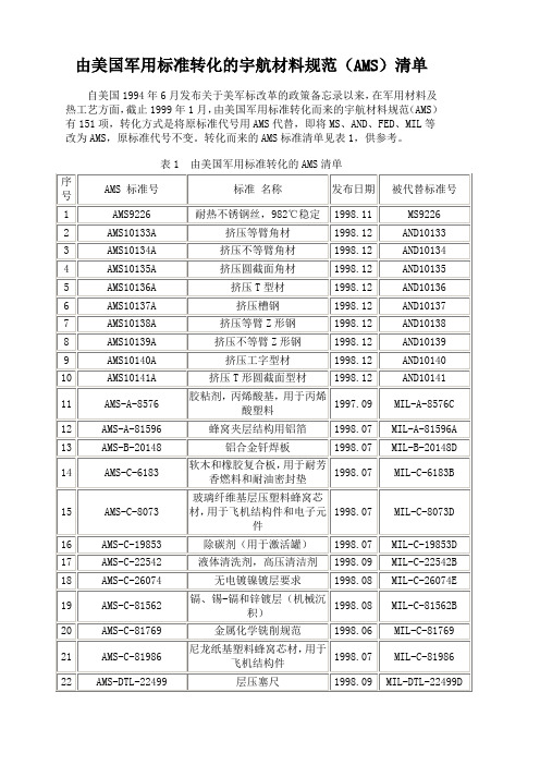
由美国军用标准转化的宇航材料规范(AMS)清单
自美国1994年6月发布关于美军标改革的政策备忘录以来,在军用材料及热工艺方面,截止1999年1月,由美国军用标准转化而来的宇航材料规范(AMS)有151项,转化方式是将原标准代号用AMS代替,即将MS、AND、FED、MIL等改为AMS,原标准代号不变。
转化而来的AMS标准清单见表1,供参考。
表1 由美国军用标准转化的AMS清单
注:AND——美国空、海军航空设计标准(Air Force-Navy Aeronautical Design Standards, DOD);AS——美国宇航标准(Aerospace Standards, SAE);FED——美国联邦标准(FEDeral Standards);MIL——美国军用标准(MILitary Standards, DOD);MS——美国军用标准图纸(Military Standard Drawings);QQ——美国联邦规范(Federal Specifications)。
日本新光电子秤中文说明书

两个限定值
HI(过重) 样品重量高于上限定值
OK(适中) 样品重量在上限定值与下限定值之间, 或等于两个限值
LO(过轻) 样品重量低于下限定值
一个限定值 没有显示 样品重量等于或高于下限定值 样品重量低于下限定值
9.1 比较功能设定 1.
长按“Function”键, 直至显示屏显示“
”
放手后, 现在进入功能模式, 显示屏显“
3.
按“Zero/Tare”键, 最右方数值会改变,
按数次, 直到显示屏显示用户需要的设定
(设定代码详见 5.2 表格)
4.
按“Set” 键, 结束功能设定,回到测量模式.
P. 4
5.2 功能設定表格
功能 横杠 比较测定功能
判别环境 只在比较测 定功能激活 判别范围 时看到
判别点 零位跟踪 自动关机
P. 8
9. 比较测定功能
P. 8
10. 校准
P.11
11. 输入/输出
P.12
P. 1
1. 使用注意事项: (使用前请先看此部份)
1. 请勿量重高于负载. (注意在使用除皮功能时, 容器和测量物件的总重量, 不能超过负载) 2. 请勿让天平受到撞击 3. 清洗天平时, 请用温和清洁剂, 切勿使用溶剂 4. 在移动天平时, 秤盘不能盛载物件 5. 请勿自行把天平拆开
此功能在(称重、计数、百分比)测量模式都有效,而每个模式设定的限定值是不同的。
P. 8
限定值设定方法:
你有两种方法设定限定值: (a) 实际负载设定限值,称重一样品,并储存其重量。 (b) 输入数值设定限值,用面板上的键输入限定值。
判别指示:
通过在显示屏上信号 “ ” 的位置来判别.如下表
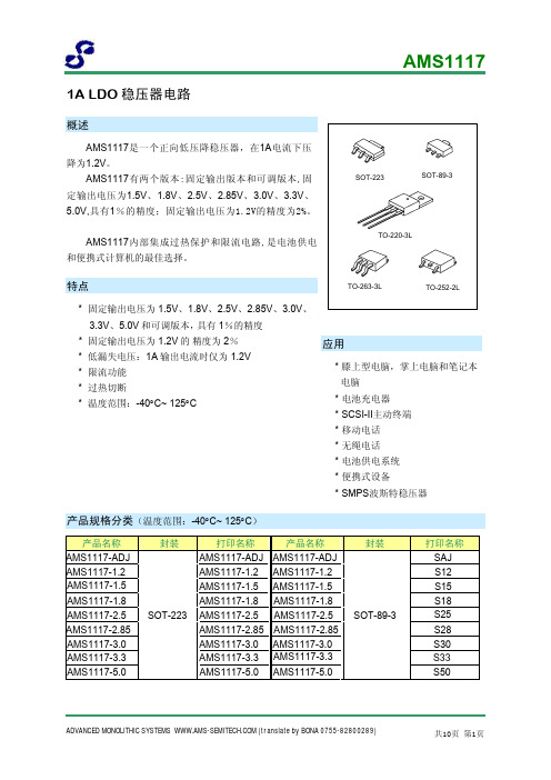
AMS117中文资料
线性瞬态响应(VOUT=2.85V)
线性瞬态响应(VOUT=5 V)
ADVANCED MONOLITHIC SYSTEMS (translate by BONA 0755-82800289)
共10页 第4页
管脚排列图
AMS1117
AMS1117
AMS1117
AMS1117
AMS1117
AMS1117
管脚描述
管脚号 1 2 3
管脚名称 GND/ADJ
VOUT VIN
I/O
--/O 地/ADJ。
O
输出电压。
I
输入工作电压。
功能
ADVANCED MONOLITHIC SYSTEMS (translate by BONA 0755-82800289)
产品名称
AMS1117-ADJ AMS1117-1.2 AMS1117-1.5 AMS1117-1.8 AMS1117-2.5 AMS1117-2.85 AMS1117-3.0 AMS1117-3.3 AMS1117-5.0 AMS1117-ADJ AMS1117-1.2 AMS1117-1.5 AMS1117-1.8 AMS1117-2.5
AMS1117内部集成过热保护和限流电路,是电池供电 和便携式计算机的最佳选择。
SOT-223
SOT-89-3
TO-220-3L
特点
TO-263-3L
TO-252-2L
* 固定输出电压为 1.5V、1.8V、2.5V、2.85V、3.0V、 3.3V、5.0V 和可调版本,具有 1%的精度
* 固定输出电压为 1.2V 的 精度为 2% * 低漏失电压:1A 输出电流时仅为 1.2V * 限流功能 * 过热切断 * 温度范围:-40°C~ 125°C
SAE AMS-2750E 高温测定法(中英文对照版)

3. TECHNICAL REQUIREMENTS 技术要求............................................................................................................................................................................................ 12
图1
负载传感器的再使用和重新校检........................................................................................................................................... 21
5. PREPARATION FOR DELIVERY 交货准备............................................................................................................................................................................................ 70
深圳市维科特机电有限公司AM22070H说明书

深圳市维科特机电有限公司AM22070H产品说明书在86及110、130混合式步进电机的应用中(主要需求点为900RPM以内,高转矩、高响应、高性价比的定位控制,或者变频调速控制),三相混合式步进电机应用最为广泛。
但在某些国家(例如印度、土耳其、阿根廷等国),以及某些行业中(例如大中型木工雕机、单头绣花机、花样机等),由于使用习惯及发展历史等原因,依然采用两相步进电机及高压型两相步进电机驱动器。
传统模拟式两相步进电机驱动器由于控制算法、发热等方面的原因普遍使用交流110V供电,交流220V供电会导致电机发热非常厉害而无法使用;新型数字式两相步进电机驱动器在算法方面做了较大提升,即使工作在交流220V时,依然能够在发热、平稳性、稳定性等方面做到较好的平衡。
该驱动器使用最为典型的行业为单头绣花机、大幅面花样机、定长送料机、中大型木工雕刻机等。
AM22070以各行业客户对高压型2相步进电机驱动器的需求为目标,以行业应用经验为基础,以为客户提供高性价比、高稳定性的产品为宗旨。
整套控制方案在充分吸收和掌握国外先进技术的基础上进行深入优化和提炼而成。
硬件设计上充分考虑强弱电隔离、输入信号兼容、关键物料选用国际知名厂家经典、成熟的元器件;软件上采用自创的两相步进电机驱动器矢量控制技术及其快速算法,并具备自测试运行、单双脉冲模式设置、多重保护等功能。
特点单电源输入,电压范围:交流AC110-240V,相比传统110V供电的驱动器,可以省掉一个变压器,相同转速下输出力矩更大;驱动电流从有效值1.2A/相到7A/相分16档可调;16档细分配置,最高分辨率40000步/转;细分配置小于等于2000步/转时采用微细分控制方式;最高响应频率可达200KHz;相位记忆功能:断电时能自动记忆电机转子位置;保护功能:过热保护/过流保护、相间短路保护、断线保护、过压保护;自动半流:输入脉冲脉冲停止超过100ms时,电流自动减半,减少电机发热;全隔离:信号输入输出隔离;强弱电隔离(pwm控制信号及电流采样均隔离);5V/24V信号输入兼容设计;控制模式可选:脉冲/方向模式;或者双脉冲输入模式;自测试功能:无需外界脉冲信号即可驱动电机以30转/分钟的速度转动;体积为83x202x147(mm^3),推荐安装空间至少为100x230x200(mm^3);净重:1.5kg(加包装箱1.7kg);颜色:白色;采用工业级芯片设计,运行环境温度:-25゜~+60゜(0゜以下不结冰);采用矢量控制及微细分控制技术,在运行平稳性、噪音、震动、发热等方面较传统驱动器均有较大的提升;应用领域灌胶机木雕机激光切割机数控机床包装设备单头绣花机花样机缝纫机钻孔机电流设定驱动器工作电流IM(以下简称IM)由D1-D4拨码开关设定(注:工作电流为正常运行时的电流有效值给定,抱轴时的电流则为对应工作电流的50%,简称自动半流。
亚摩普电子测试仪数据册说明书

Constant voltage / variable current measurement
Range Resolution Tolerance
0.05 to 19.99 Ω; 20 to 199.9 Ω; 200 to 1999 Ω 0.01 Ω; 0.1 Ω; 1 Ω ±(4% rdg. + 2 digits )
allows the application in sandy as well in rocky environments ■■ Monitoring and display of auxiliary earth and probe resistances ■■ Displays the actual test current ■■ Automatic and manual and frequency selection for noise reduction ■■ Test voltage pre-selection ■■ Clear and large digital display provides the user with an optimum visual indication of both test values and limits ■■ Auto power off ■■ Specific earth resistance measurement in compliance with the Wenner principle
Amprobe® Test Tools Europe Amprobe Test Tools Europe Beha-Amprobe GmbH In den Engematten 14 79286 Glottertal, Germany Tel.: +49 (0) 7684 8009 - 0
ACS244MS中文资料

1CAUTION: These devices are sensitive to electrostatic discharge; follow proper IC Handling Procedures.1-888-INTERSIL or 321-724-7143|Copyright © Intersil Corporation 1999March 1998ACS244MSRadiation Hardened Non-Inverting,Octal, Three-State Buffer/Line DriverFeatures•QML Qualified Per MIL-PRF-38535 Requirements • 1.25Micron Radiation Hardened SOS CMOS•Radiation Environment-Latch-up Free Under any Conditions-Total Dose. . . . . . . . . . . . . . . . . . . . . .3 x 105RAD(Si)-SEU Immunity. . . . . . . . . . .<1 x 10⁻¹⁰ Errors/Bit/Day -SEU LET Threshold . . . . . . . . . . .>100MeV/(mg/cm 2)•Input Logic Levels .V IL = (0.3V)(V CC ), V IH = (0.7V)(V CC )•Output Current. . . . . . . . . . . . . . . . . . . . . . . . . . .±16mA •Quiescent Supply Current. . . . . . . . . . . . . . . . . . . .20µA •Propagation Delay . . . . . . . . . . . . . . . . . . . . . . . . .9.0nsApplications•Databus Driving •Data Routing•Redundant Data Control CircuitryDescriptionThe Radiation Hardened ACS244MS is a Non-Inverting,Octal, Three-State Buffer/Line Driver with two active-LOW Enable inputs (AE and BE). Each Enable input controls four outputs. When an Enable input is LOW, the corresponding outputs are active. A HIGH on an Enable input causes the corresponding outputs to be high impedance, regardless of the input levels.The ACS244MS is fabricated on a CMOS Silicon on Sap-phire (SOS) process, which provides an immunity to Single Event Latch-up and the capability of highly reliable perfor-mance in any radiation environment. These devices offer significant power reduction and faster performance when compared to ALSTTL types.Specifications for Rad Hard QML devices are controlled by the Defense Supply Center in Columbus (DSCC). The SMD numbers listed below must be used when ordering.Detailed Electrical Specifications for the ACS244 are contained in SMD 5962-98541. A “hot-link” is provided on our homepage with instructions for downloading./data/sm/index.htmOrdering InformationPinoutsACS244 (SBDIP)TOP VIEWACS244 (FLATPACK)TOP VIEWSMD PART NUMBER INTERSIL PART NUMBER TEMP. RANGE (o C)PACKAGE CASE OUTLINE 5962F9854101VRC ACS244DMSR-02-55 to 12520 Ld SBDIP CDIP2-T20N/AACS244D/Sample-022520 Ld SBDIP CDIP2-T205962F9854101VXC ACS244KMSR-02-55 to 12520 Ld Flatpack CDFP4-F20N/A ACS244K/Sample-022520 Ld Flatpack CDFP4-F20N/AACS244HMSR-0225DieN/A1112131415161718201910987654321AE AI1BO4AI2BO3AI3AI4BO2BO1GND V CC AO1BI4AO2BE BI3AO3BI2AO4BI12345678120191817161514139101211AE AI1BO4AI2BO3AI3AI4BO2BO1GNDV CC AO1BI4AO2BE BI3AO3BI2AO4BI1File Number44792All Intersil semiconductor products are manufactured, assembled and tested under ISO9000 quality systems certification.Intersil products are sold by description only. Intersil Corporation reserves the right to make changes in circuit design and/or specifications at any time without notice. Accordingly, the reader is cautioned to verify that data sheets are current before placing orders. Information furnished by Intersil is believed to be accurate and reliable. However, no responsibility is assumed by Intersil or its subsidiaries for its use; nor for any infringements of patents or other rights of third parties which may result from its use. No license is granted by implication or otherwise under any patent or patent rights of Intersil or its subsidiaries.For information regarding Intersil Corporation and its products, see web site Sales Office HeadquartersNORTH AMERICA Intersil CorporationP. O. Box 883, Mail Stop 53-204Melbourne, FL 32902TEL:(321) 724-7000FAX: (321) 724-7240EUROPE Intersil SAMercure Center100, Rue de la Fusee 1130 Brussels, Belgium TEL: (32) 2.724.2111FAX: (32) 2.724.22.05ASIAIntersil (Taiwan) Ltd.Taiwan Limited7F-6, No. 101 Fu Hsing North Road Taipei, Taiwan Republic of ChinaTEL: (886) 2 2716 9310FAX: (886) 2 2715 3029Die CharacteristicsDIE DIMENSIONS:Size:2540µm x 2540µm (100 mils x 100mils)Thickness:525µm ±25µm (20.6 mils ±1 mil)Bond Pad: 110µm x 110µm (4.3 x 4.3 mils)METALLIZATION:AlMetal 1 Thickness: 0.7µm ±0.1µm Metal 2 Thickness: 1.0µm ±0.1µm SUBSTRATE POTENTIAL:Unbiased InsulatorPASSIVATIONType: Phosphorous Silicon Glass (PSG)Thickness: 1.30µm ±0.15µm SPECIAL INSTRUCTIONS:Bond V CC FirstADDITIONAL INFORMATION:Worst Case Density:<2.0 x 10⁵ A/cm 2Transistor Count:214Metallization Mask LayoutACS244MSBO4 (3)AI2 (4)BO3 (5)AI3 (6)BO2 (7)AI4 (8)V CC BO1 (9)AO4 (12)(13)BI2(14)AO3(15)BI3(16)AO2(17)BI4(18)AO1(20)V CC (20)AE (1)AI1(2)BE (19)(11)BI1(10)GND (10)GND ACS244MS。
LC245A中文资料
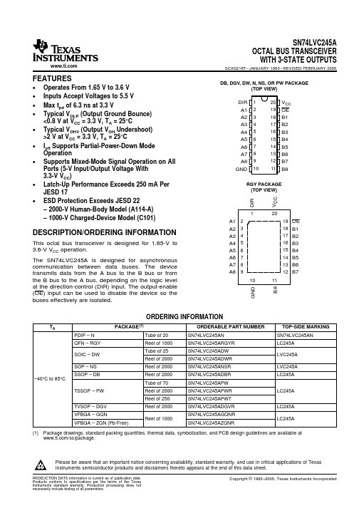
GQN OR ZQN PACKAGE (TOP VIEW)
1234
A B C D E
TERMINAL ASSIGNMENTS
1
2
3
4
A
A1
DIR
VCC
OE
B
A3
B2
A2
B1
C
A5
A4
B4
B3
D
A7
B6
A6
B5
E
GND
A8
B8
B7
FUNCTION TABLE
INPUTS
OE DIR
L
L
L
H
H
X
OPERATION
QFN – RGY
Reel of 1000
SN74LVC245ARGYR
SOIC – DW
Tube of 25 Reel of 2000
SN74LVC245ADW SN74LVC245ADWR
SOP – NS
Reel of 2000
SN74LVC245ANSR
SSOP – DB
Reel of 2000
Please be aware that an important notice concerning availability, standard warranty, and use in critical applications of Texas Instruments semiconductor products and disclaimers thereto appears at the end of this data sheet.
DIR 1 A1 2 A2 3 A3 4 A4 5 A5 6 A6 7 A7 8 A8 9 GND 10
由美国军用标准转化的宇航材料规范
自美国1994年6月发布关于美军标改革的政策备忘录以来,在军用材料及热工艺方面,截止1999年1月,由美国军用标准转化而来的宇航材料规范(AMS)有151项,转化方式是将原标准代号用AMS代替,即将MS、AND、FED、MIL等改为AMS,原标准代号不变。转化而来的AMS标准清单见表1,供参考。
27
AMS-G-952A
喷枪、喷射液、油和溶剂
1998.03
MIL-G-952
28
AMS-H-6088A
铝合金热处理
1998.12
MIL-H-6088
29
AMS-H-6875A
钢原材料热处理
1998.12
MIL-H-6875H
30
AMS-H-7199
变形铜-铍合金(第C17000、C17200、C17300、C17500和C17510号铜合金)热处理工艺
1997.07
QQ-A-225/4
68
AMS-QQ-A-225/5
2017铝合金轧制、拉制或冷精整的圆棒、方棒、线材
1997.07
QQ-A-225/5
69
AMS-QQ-A-225/6A
2024铝合金轧制、拉制或冷精整的圆棒、方棒、线材
1998.09
QQ-A-225/6
70
AMS-QQ-A-225/7
1998.12
AND10135
5
AMS10136A
挤压T型材
1998.12
AND10136
6
AMS10137A
挤压槽钢
1998.12
AND10137
7
AMS10138A
挤压等臂Z形钢
CM15-2249中文资料
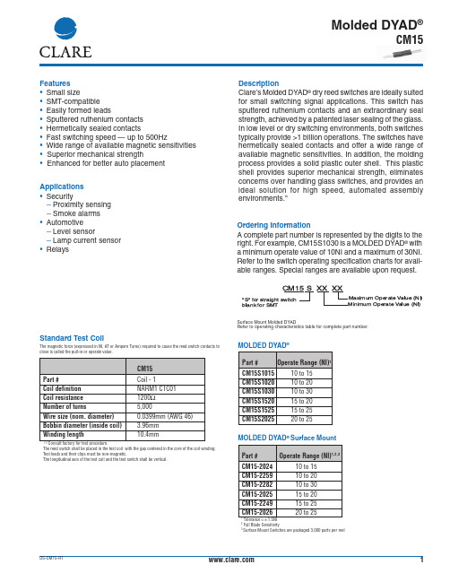
Clare’s Molded DYAD ® dry reed switches are ideally suited for small switching signal applications. This switch has sputtered ruthenium contacts and an extraordinary seal strength, achieved by a patented laser sealing of the glass.In low level or dry switching environments, both switches typically provide >1 billion operations. The switches have hermetically sealed contacts and offer a wide range of available magnetic sensitivities. In addition, the molding process provides a solid plastic outer shell. This plastic shell provides superior mechanical strength, eliminates concerns over handling glass switches, and provides an ideal solution for high speed, automated assembly environments."Features Description•Small size•SMT-compatible •Easily formed leads•Sputtered ruthenium contacts •Hermetically sealed contacts•Fast switching speed — up to 500Hz•Wide range of available magnetic sensitivities • Superior mechanical strength• Enhanced for better auto placement Applications •Security−Proximity sensing −Smoke alarms •Automotive −Level sensor−Lamp current sensor •RelaysStandard Test CoilThe magnetic force (expressed in NI, AT or Ampere Turns) required to cause the reed switch contacts to close is called the pull-in or operate value.Ordering InformationA complete part number is represented by the digits to the right. For example, CM15S1030 is a MOLDED DYAD ® with a minimum operate value of 10NI and a maximum of 30NI.Refer to the switch operating specification charts for avail-able ranges. Special ranges are available upon request.Surface Mount Molded DYADRefer to operating characteristics table for complete part number.Molded DYAD ®(1)The reed switch shall be placed in the test coil with the gap centered in the core of the coil winding.Test leads and their clips must be non-magnetic.The longitudinal axis of the test coil and the test switch shall be vertical.MOLDED DYAD ®MOLDED DYAD ®Surface Mount 2Full Blade Sensitivity 3Surface Mount Switches are packaged 3,000 parts per reel1CM15DS-CM15-R1Maximum Operate Value (NI)Minimum Operate Value (NI)CM15S XX XX"S"for straight switch blank for SMTCM15Rev. 1Specificationsin excess of these ratings can cause permanent damage to the device. Functional operation of the device at these or any other conditions beyond those indicated in the operational sections of this data sheet is not implied.Exposure of the device to the absolute maximum ratings for extended period may degrade the device and effect its reliability.(1) Contact resistance measured with 4 terminal method, 1.1" between test leads (2)>1012 Ω is available upon request (3)A 24V zener in series with a diode across the coil (4)Use caution not to exceed vibration resistance limits while ultrasonically cleaning. Contact Clare Engineering for more details/recommendations (5)15 ampere turn minimumMolded DYAD ®2CM15Rev. 1Mechanical DimensionsDIMENSIONSmm (inches)Molded DYAD ®3CLARE LOCATIONSClare Headquarters78 Cherry Hill DriveBeverly, MA 01915Tel: 1-978-524-6700Fax: 1-978-524-4900Toll Free: 1-800-27-CLARE Clare Switch Division4315 Earth City Expresssway St. Louis, MO 63045Tel: 1-314-770-1832Fax: 1-314-770-1812Clare Micronix Division145 ColumbiaAliso Viejo, CA 92656-1490 Tel: 1-949-831-4622Fax: 1-949-831-4628SALES OFFICES AMERICASAmericas HeadquartersClare78 Cherry Hill DriveBeverly, MA 01915Tel: 1-978-524-6700Fax: 1-978-524-4900Toll Free: 1-800-27-CLARE Eastern RegionClareP.O. Box 856Mahwah, NJ 07430Tel: 1-201-236-0101Fax: 1-201-236-8685Toll Free: 1-800-27-CLARE Central RegionClare Canada Ltd.3425 Harvester Road, Suite 202 Burlington, Ontario L7N 3N1 Tel: 1-905-333-9066Fax: 1-905-333-1824Western RegionClare1852 West 11th Street, #348 Tracy, CA 95376Tel: 1-209-832-4367Fax: 1-209-832-4732Toll Free: 1-800-27-CLARE CanadaClare Canada Ltd.3425 Harvester Road, Suite 202 Burlington, Ontario L7N 3N1 Tel: 1-905-333-9066Fax: 1-905-333-1824EUROPEEuropean HeadquartersCP Clare nvBampslaan 17B-3500 Hasselt (Belgium)Tel: 32-11-300868Fax: 32-11-300890FranceClare France SalesLead Rep99 route de Versailles91160 ChamplanFranceTel: 33 1 69 79 93 50Fax: 33 1 69 79 93 59GermanyClare Germany SalesActiveComp Electronic GmbHMitterstrasse 1285077 ManchingGermanyTel: 49 8459 3214 10Fax: 49 8459 3214 29ItalyC.L.A.R.E.s.a.s.Via C. Colombo 10/AI-20066 Melzo (Milano)Tel: 39-02-95737160Fax: 39-02-95738829SwedenClare SalesComptronic ABBox 167S-16329 SpångaTel: 46-862-10370Fax: 46-862-10371United KingdomClare UK SalesMarco Polo HouseCook WayBindon RoadTauntonUK-Somerset TA2 6BGTel: 44-1-823 352541Fax: 44-1-823 352797ASIA PACIFICAsian HeadquartersClareRoom N1016, Chia-Hsin, Bldg II,10F, No. 96, Sec. 2Chung Shan North RoadTaipei, Taiwan R.O.C.Tel: 886-2-2523-6368Fax: 886-2-2523-6369Worldwide Sales OfficesSpecification: PB-CM15-R1©Copyright 2001Molded Ultra-Mini DYAD™, Molded Mini DYAD™, andMolded DYAD® are trademarks of Clare, Inc.All rights reserved. Printed in USA.4/23/01Clare cannot assume responsibility for use of any circuitry otherthan circuitry entirely embodied in this Clare product. No circuitpatent licenses nor indemnity are expressed or implied. Clare re-serves the right to change the specification and circuitry, withoutnotice at any time. The products described in this document are notintended for use in medical implantation or other direct life supportapplications where malfunction may result in direct physical harm,injury or death to a person.。
由美国军用标准转化的宇航材料规范

由美国军用标准转化的宇航材料规范
公司标准化编码 [QQX96QT-XQQB89Q8-NQQJ6Q8-MQM9N]
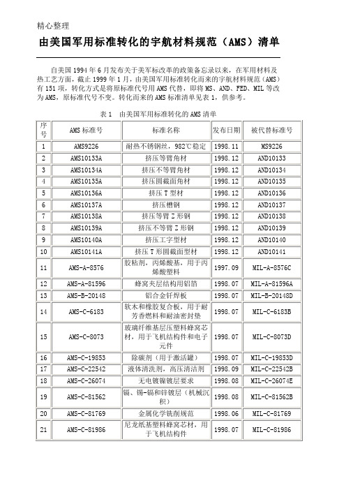
由美国军用标准转化的宇航材料规范(AMS)清单
自美国1994年6月发布关于美军标改革的政策备忘录以来,在军用材料及热工艺方面,截止1999年1月,由美国军用标准转化而来的宇航材料规范(AMS)有151项,转化方式是将原标准代号用AMS代替,即将MS、AND、FED、MIL等改为AMS,原标准代号不变。
转化而来的AMS标准清单见表1,供参考。
表1由美国军用标准转化的AMS清单
注:AND——美国空、海军航空设计标准(Air Force-Navy Aeronautical Design Standards, DOD);AS——美国宇航标准(Aerospace Standards, SAE);FED——美国联邦标准(FEDeral Standards);MIL——美国军用标准(MILitary Standards, DOD);MS——美国军用标准图纸(Military Standard Drawings);QQ——美国联邦规范(Federal Specifications)。
AMS2249F
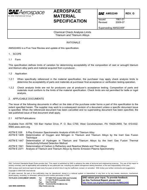
__________________________________________________________________________________________________________________________________________ SAE Technical Standards Board Rules provide that: “This report is published by SAE to advance the state of technical and engineering sciences. The use of this report is entirely voluntary, and its applicability and suitability for any particular use, including any patent infringement arising therefrom, is the sole responsibility of the user.” SAE reviews each technical report at least every five years at which time it may be reaffirmed, revised, or cancelled. SAE invites your written comments and suggestions. Copyright © 2009 SAE InternationalAll rights reserved. No part of this publication may be reproduced, stored in a retrieval system or transmitted, in any form or by any means, electronic, mechanical, photocopying, recording, or otherwise, without the prior written permission of SAE.TO PLACE A DOCUMENT ORDER:Tel: 877-606-7323 (inside USA and Canada)Tel: +1 724-776-4970 (outside USA)Fax: 724-776-0790Email: CustomerService@ SAE WEB ADDRESS: h ttp://SAE values your input. To provide feedback on this Technical Report, please visit /technical/standards/AMS2249GAEROSPACE MATERIAL SPECIFICATIONAMS2249 REV. G Issued 1961-01 Revised 2009-07 Superseding AMS2249FChemical Check Analysis LimitsTitanium and Titanium AlloysRATIONALE AMS2249G is a Five Year Review and update of this specification.1. SCOPE1.1 FormThis specification defines limits of variation for determining acceptability of the composition of cast or wrought titanium and titanium alloy parts and material acquired from a producer.1.2 Application1.2.1 When specifically referenced in the material specification, the purchaser may apply check analysis limits todetermine the acceptability of parts and materials at purchaser final acceptance or verification testing operation.1.2.2 Check analysis limits are not for producers use at producer’s acceptance testing. Composition of parts andmaterials must conform to the limits of the material specification. Check limits are not permitted for ladle or ingot analysis.2. APPLICABLE DOCUMENTSThe issue of the following documents in effect on the date of the purchase order forms a part of this specification to the extent specified herein. The supplier may work to a subsequent revision of a document unless a specific document issue is specified. When the referenced document has been cancelled and no superseding document has been specified, the last published issue of that document shall apply.2.1 ASTM PublicationsAvailable from ASTM, 100 Barr Harbor Drive, P. O. Box C700, West Conshohocken, PA 19428-2959, Tel: 610-832-9585,.ASTM E 539 X-Ray Emission Spectrometric Analysis of 6AI-4V Titanium AlloyASTM E 1409 Determination of Oxygen and Nitrogen in Titanium and Titanium Alloys by the Inert Gas FusionTechniqueASTM E 1447 Determination of Hydrogen in Titanium and Titanium Alloys by the Inert Gas Fusion ThermalConductivity/Infrared Detection MethodASTM E 1941 Determination of Carbon in Refractory and Reactive Metals and Their AlloysASTM E 2371 Analysis of Titanium and Titanium Alloys by Atomic Emission Plasma Spectrometry--`,,```````,,`,`,,````-`-`,,`,,`,`,,`---3. TECHNICAL REQUIREMENTS3.1 Analytical ProceduresReferee methods of analysis shall be ASTM E 1409 for oxygen and nitrogen, ASTM E 1447 for hydrogen, and ASTM E 1941 for carbon. Other elements shall be determined by ASTM E 2371, or ASTM E 539 for 6Al–4V.3.2 Check (Product) Analysis LimitsShall be shown in Table 1. Check analysis limits for elements or for ranges of elements not listed herein shall be as specified in the applicable material specification or as agreed upon by purchaser and vendor.TABLE 1 - CHECK ANALYSIS LIMITSElement Limits or Maximum ofSpecified Range, %VariationUnder Min or Over MaxCarbon Up to0.20,incl 0.02 Over0.20to0.50,incl 0.04Over0.500.06Manganese Up to0.30,incl 0.10Over0.30to 6.00,incl 0.20Over 6.00to9.00,incl 0.25Chromium Up to 1.00,incl 0.05 Over 1.00to 4.00,incl 0.20Over 4.000.25Molybdenum Up to0.50,incl 0.04Over0.50to 1.00,incl 0.10Over 1.00to10.00,incl 0.20Over10.00to30.00,incl 0.25Aluminum Up to 1.00,incl 0.12 Over 1.00to10.00,incl 0.40Over10.00to30.00,incl 0.50Hydrogen Up to0.020,( 200 ppm), incl 0.0020 ( 20 ppm)Over0.020to0.050,( 200 to 500 ppm), incl 0.005 ( 50 ppm)Over0.050( 500 ppm), 0.010 (100 ppm)Nitrogen Up to0.10,(1000 ppm), incl 0.02 (200 ppm)Oxygen Up to0.20,(2000 ppm), incl 0.02 (200 ppm)Over0.20(2000 ppm) 0.03 (300 ppm)Iron Up to0.25,incl 0.10 Over0.25to0.50,incl 0.15Over0.50to 5.00,incl 0.20Over 5.000.25Vanadium Up to0.50,incl 0.05 Over0.50to 5.00,incl 0.15Over 5.00to 6.00,incl 0.20Over 6.00to10.00,incl 0.30Over10.00to20.00,incl 0.40Tin Up to 3.00,incl 0.15 Over 3.00to 6.00,incl 0.25Over 6.00to12.00,incl 0.40Copper Up to 1.00,incl 0.05 Over 1.00to 3.00,incl 0.10--`,,```````,,`,`,,````-`-`,,`,,`,`,,`TABLE 1 - CHECK ANALYSIS LIMITS (CONTINUED)Element Limits or Maximum ofSpecified Range, %VariationUnder Min or Over MaxZirconium Up to 4.00,incl0.10Over 4.00to 6.00,incl 0.20Over 6.00to10.00,incl 0.30Over10.000.40Columbium Up to 1.00,incl 0.10Over 1.00to 5.00,incl 0.15Over 5.00to7.00,incl 0.20Over7.00to10.00,incl 0.25Over10.00to15.00,incl 0.30Over15.00to20.00,incl 0.35Over20.00to30.00,incl 0.40Tantalum Up to0.50,incl 0.10Over0.50to 2.00,incl 0.15Silicon Up to0.10,incl 0.02Over0.10to0.50,incl 0.05Bismuth Up to0.50,incl 0.05Yttrium Up to0.005,incl 0.0006Over0.005to0.020,incl 0.001Boron Up to0.005,incl 0.0006Palladium Up to0.250,incl0.02Nickel Up to 1.00,incl 0.03Tungsten Up to 1.00,incl 0.04Over 1.00to 3.00,incl 0.10Over 3.00to 5.00,incl 0.15Over 5.00to10.00,incl 0.204. QUALITY ASSURANCE PROVISIONS4.1 Sampling and TestingFor the purpose of determining conformance to the material specification composition requirement, each heat or lot, whichever is applicable, in the shipment shall be considered separately. All samples shall be taken from material in the condition in which it is received, except that all protective surface treatments shall be removed before sampling finished parts. Drillings, chips, and other samples shall be taken without the application of water, oil, or other lubricants and shall be free from scale, grease, dirt, and other foreign materials. Samples shall be taken to prevent alteration of the chemical composition of the sample.5. PREPARATION FOR DELIVERYNot applicable.6. AC NOWLEDGMENTNot applicable.7. REJECTIONSNot applicable.--`,,```````,,`,`,,````-`-`,,`,,`,`,,`---8. NOTES8.1 A change bar (|) located in the left margin is for the convenience of the user in locating areas where technicalrevisions, not editorial changes, have been made to the previous issue of this document. An (R) symbol to the left of the document title indicates a complete revision of the document, including technical revisions. Change bars and (R) are not used in original publications, nor in documents that contain editorial changes only.8.2 Terms used in AMS are clarified in ARP1917 and as follows:Analysis8.2.1 CheckAn analysis made by purchaser or vendor of the metal after it has been worked into semi-finished or finished forms or fabricated into parts, and is either for the purpose of verifying the composition of a heat or lot or to determine variations in the composition within the heat. Acceptance or rejection of a heat or lot of material or batch of parts may be made by the purchaser on the basis of this check analysis. In the analysis of finished parts, these values do not apply to elements whose percentage can be varied by fabricating techniques employed (for example oxygen, nitrogen, hydrogen) unless the sample is sufficiently large to produce a reliable result.8.2.2 Variation Limit, Under Minimum or Over MaximumGiven in Table 1 is the amount an individual determination for a specified element may vary under or over the specified composition limit. In no case shall the several determinations of any element in a heat, using the same analytical procedure, vary both above and below the specified range. These variations are not permitted for ingot analyses made by the producer.8.2.3 RemainderShows the basis element from which the alloy is made and is assumed to be present in an amount approximately equal to the difference between 100% and the sum percentage of the alloying elements and listed impurities. Analysis for this element need not be made nor need a percentage figure be reported.8.2.4 Other Elements, Each, MaximumThe maximum amount of an individual element not mentioned specifically in the tabulated composition that may be present. Producer normally will analyze only for impurities which are possible to be present because of raw materials or manufacturing processes and which may affect the product significantly. Others will analyze for impurities as they deem necessary.8.2.5 Other Elements, Total, MaximumThe sum percentage of the other (residual) elements (See 8.2.4) found. It is not inferred by this statement that an analysis need be made for each element of the periodic table not mentioned specifically in the tabulated composition.8.2.6 HeatAll metal that, during the final melting operation, is melted in the same furnace crucible and solidified in the same ingot mold.8.2.7 LotAll product of the same size processed at the same time from the same heat.PREPARED BY AMS COMMITTEE “G”--`,,```````,,`,`,,````-`-`,,`,,`,`,,`---。
LM224AM中文资料
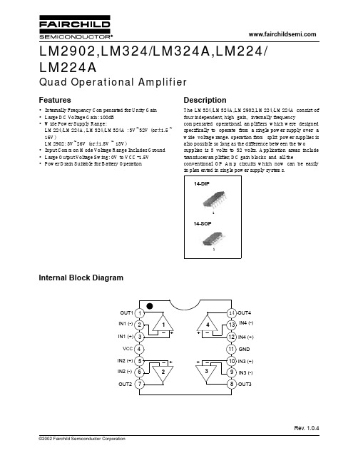
Description
The LM324/LM324A,LM2902,LM224/LM224A consist of four independent, high gain, internally frequency compensated operational amplifiers which were designed specifically to operate from a single power supply over a wide voltage range. operation from split power supplies is also possible so long as the difference between the two supplies is 3 volts to 32 volts. Application areas include transducer amplifier, DC gain blocks and all the conventional OP Amp circuits which now can be easily implemented in single power supply systems.
VO(P) = 2V
Output Current
ISINK
VI(+) = 0V, VI(-) = 1V VCC = 15V, VO(P) = 2V
10 13 - 5 8 - 5 8 - mA
Differential Input Voltage
VI(DIFF)
-
- - VCC - - VCC - - VCC V
ISC VCC = 15V
- 40 60 - 40 60 - 40 60 mA
由美国军用标准转化的宇航材料规范

由美国军用标准转化的宇航材料规范(AMS)清单
自美国1994年6月发布关于美军标改革的政策备忘录以来,在军用材料及热工艺方面,截止1999年1月,由美国军用标准转化而来的宇航材料规范(AMS)有151项,转化方式是将原标准代号用AMS代替,即将MS、AND、FED、MIL等改为AMS,原标准代号不变。
转化而来的AMS标准清单见表1,供参考。
表1 由美国军用标准转化的AMS清单
注:AND——美国空、海军航空设计标准(Air Force-Navy Aeronautical Design Standards, DOD);AS——美国宇航标准(Aerospace Standards, SAE);FED——美国联邦标准(FEDeral Standards);MIL——美国军用标准(MILitary Standards, DOD);MS——美国军用标准图纸(Military Standard Drawings);QQ——美国联邦规范(Federal Specifications)。
sgm44599
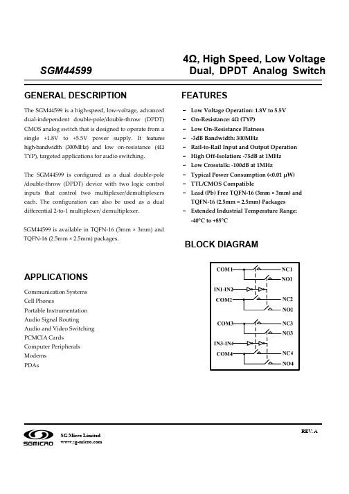
4Ω, High Speed, Low Voltage SGM44599 Dual, DPDT Analog SwitchREV. A SG Micro LimitedSGM445992ORDERING INFORMATIONMODELPIN- PACKAGESPECIFIED TEMPERATURERANGE ORDERING NUMBER PACKAGE MARKING PACKAGE OPTION TQFN-16 (2.5mm×2.5mm)-40°C to +85°C SGM44599YTQB16/TR 44599 Tape and Reel, 3000SGM44599TQFN-16 (3mm×3mm)-40°C to +85°CSGM44599YTQ16/TR44599Tape and Reel, 3000ABSOLUTE MAXIMUM RATINGSV + to GND......................................................................-0.3V to +6V Analog, Digital voltage range….................... - 0.3V to (V + + 0.3V) Continuous Current NO, NC, or COM ..........................±150mA Peak Current NO, NC, or COM ......................................±200mA Operating Temperature Range............................- 40°C to +85°C Junction Temperature..........................................................+150°C Storage Temperature........................................... - 65°C to +150°C Lead Temperature (soldering, 10s).......................................260°C ESD SusceptibilityHBM..........................................................................................2000V MM. (200V)Stresses beyond those listed under “Absolute Maximum Ratings” may cause permanent damage to the device. These are stress ratings only, and functional operation of the device at these or any other conditions beyond those indicated in the operational sections of the specifications is not implied. Exposure to absolute maximum rating conditions for extended periods may affect device reliability.PIN CONFIGURATIONS (TOP VIEW)FUNCTION TABLEFunctionIN1-IN2NC1 and NC2 NO1 and NO20 ON OFF 1 OFF ONFunctionIN3-IN4NC3 and NC4 NO3 and NO40 ON OFF 1 OFF ONSGM445993PIN DESCRIPTIONPINNAME TQFN-16 (3mm×3mm)TQFN-16(2.5mm×2.5mm)FUNCTION V + 14 Power supply GND 6 GroundIN X 2,10Digital control pin to connect the COMterminal to the NO or NC terminalsCOM X 16,4, 8, 12 Common terminal NO X 15,3, 7, 11 Normally-open terminal NC X1, 5, 9, 13 Normally-closed terminalNote: NO X , NC X and COM X terminals may be an input or output.SGM445994ELECTRICAL CHARACTERISTICS(V + = +4.5V to +5.5V, GND = 0V, V IH = +1.6V, V IL = +0.5V, T A = -40°C to +85°C. Typical values are at V + = +5.0V, T A = +25°C, unless otherwise noted.)PARAMETER SYMBOL CONDITIONS TEMP MIN TPY MAX UNITS ANALOG SWITCH Analog Signal RangeV NO , V NC , V COM-40°C to +85°C 0 V +V +25°C 4 6.2Ω On-Resistance R ON V + = 4.5V, 0V ≤ V NO or V NC ≤ V +,I COM = -100mA, Test Circuit 1 -40°C to +85°C 7.2Ω +25°C 0.4 2.6Ω On-Resistance Match BetweenChannels∆R ON V + = 4.5V, 0V ≤ V NO or V NC ≤ V +, I COM = -100mA, Test Circuit 1 -40°C to +85°C 3.1Ω +25°C 2 3.1Ω On-Resistance Flatness R FLAT(ON) V + = 4.5V, 0V ≤ V NO or V NC ≤ V +, I COM = -100mA, Test Circuit 1-40°C to +85°C 3.6Ω Source OFF Leakage Current I NC(OFF), I NO(OFF)V + =5.5V, V NO or V NC = 3.3V/ 0.3V, V COM = 0.3V/ 3.3V-40°C to +85°C 1 µA Channel ON Leakage Current I NC(ON), I NO(ON), I COM(ON) V + = 5.5V, V COM = 0.3V/ 3.3V, V NO or V NC = 0.3V/ 3.3V, or floating-40°C to +85°C1µADIGITAL INPUTS Input High Voltage V INH -40°C to +85°C 1.6 V Input Low Voltage V INL-40°C to +85°C 0.5V Input Leakage CurrentI IN V + = 5.5V, V IN = 0V or 5.5V-40°C to +85°C1µADYNAMIC CHARACTERISTICS Turn-On Time t ON +25°C 31.5 ns Turn-Off Timet OFF V NC or V NO = 3.0V, R L = 300Ω,C L = 35pF, Test Circuit2 +25°C 30.0 ns Break-Before-Make Time Delay tD V NC or V NO = 3.0V, R L = 300Ω, C L = 35pF, Test Circuit4+25°C 11.5 ns Charge Injection Q V G = GND, R G = 0Ω, C L = 1.0nF, Q = C L x V OUT , Test Circuit3 +25°C 3.5pC 1MHz +25°C -75Off IsolationO ISOSignal = 0dBm, R L = 50Ω,Test Circuit510MHz +25°C -55 dB 1MHz +25°C -100Channel-to-Channel Crosstalk X TALK Signal = 0dBm,R L = 50Ω,Test Circuit610MHz +25°C -60dB -3dB Bandwidth BWSignal = 0dBm, R L = 50Ω, Test Circuit7+25°C300MHzChannel ON Capacitance C NC(ON), C NO(ON),C COM(ON)+25°C 43.2 pFPOWER REQUIREMENTS Power Supply Range V +-40°C to +85°C 1.8 5.5V Power Supply CurrentI +V + = 5.5V, V IN = 0V or V +-40°C to +85°C1µASpecifications subject to changes without notice.SGM445995ELECTRICAL CHARACTERISTICS(V + = +2.7V to +3.6V, V IH = +1.6V, V IL = +0.4V, T A = -40°C to +85°C. Typical values are at V + = +3.0V, T A = +25°C, unless otherwise noted.)PARAMETER SYMBOL CONDITIONS TEMP MIN TPY MAX UNITS ANALOG SWITCH Analog Signal RangeV NO , V NC , V COM-40°C to +85°C 0 V +V +25°C 1015Ω On-Resistance R ON V + = 2.7V, 0V ≤ V NO or V NC ≤ V +,I COM = -100mA, Test Circuit 1 -40°C to +85°C 18Ω +25°C 1 3 Ω On-Resistance Match BetweenChannels∆R ON V + = 2.7V, 0V ≤ V NO or V NC ≤ V +, I COM = -100mA, Test Circuit 1 -40°C to +85°C 4 Ω +25°C 6 9 ΩOn-Resistance Flatness R FLAT(ON) V + = 2.7V, 0V ≤ V NO or V NC ≤ V +, I COM = -100mA, Test Circuit 1-40°C to +85°C 12Ω Source OFF Leakage Current I NC(OFF), I NO(OFF)V + = 3.6V, V NO or V NC = 3.3V / 0.3V,V COM = 0.3V/ 3.3V-40°C to +85°C 1 µA Channel ON Leakage Current I NC(ON), I NO(ON), I COM(ON) V + = 3.6V, V COM = 0.3V/ 3.3V, V NO or V NC = 0.3V/ 3.3V, or floating-40°C to +85°C1µADIGITAL INPUTS Input High Voltage V INH -40°C to +85°C 1.5 V Input Low Voltage V INL-40°C to +85°C 0.4V Input Leakage CurrentI IN V + = 2.7V, V IN = 0V or 2.7V-40°C to +85°C1µADYNAMIC CHARACTERISTICS Turn-On Time t ON +25°C 38.0 ns Turn-Off Timet OFF V NC or V NO = 1.5V, R L = 300Ω,C L = 35pF, Test Circuit2 +25°C 44.0 ns Break-Before-Make Time Delay tD V NC or V NO = 1.5V, R L = 300Ω, C L = 35pF, Test Circuit4+25°C 5.8 ns Charge Injection Q V G = GND, R G = 0Ω, C L = 1.0nF, Q = C L x V OUT, Test Circuit3 +25°C 2.6pC1MH +25°C -75 dB Off IsolationO ISOSignal = 0dBm, R L = 50Ω,Test Circuit510MHz +25°C -55 dB 1MHz +25°C -100 dB Channel-to-Channel Crosstalk X TALK Signal = 0dBm, R L = 50Ω,Test Circuit610MHz +25°C -60dB -3dB Bandwidth BW Signal = 0dBm, R L = 50Ω, Test Circuit7+25°C300MHzChannel ON CapacitanceC NC(ON), C NO(ON),C COM(ON)+25°C 43.2 pFSpecifications subject to changes without notice.SGM445996TYPICAL PERFORMANCE CHARACTERISTICSSGM445997TEST CIRCUITS100mAV NO or V NCTest Circuit 1. On ResistanceTest Circuit 2. Switching Times (t ON , t OFF )Test Circuit 3. Charge InjectionSGM445998TEST CIRCUITS (Cont.)Test Circuit 4. Break-Before-Make Time Delay (t D )Test Circuit 5. Off IsolationV OUTNO or NCV GND0.1µFV Source Signal R L 505pFChannel To Channel Crosstalk = -20V NO or V NCV OUTN.C.Test Circuit 6. Channel-to-Channel CrosstalkSGM445999TEST CIRCUITS (Cont.)Test Circuit 7. -3dB BandwidthSGM4459910PACKAGE OUTLINE DIMENSIONSTQFN-16 (3mm × 3mm)Note: All linear dimensions are in millimeters.SGM4459911PACKAGE OUTLINE DIMENSIONSTQFN-16 (2.5mm × 2.5mm)Note: All linear dimensions are in millimeters.SGM44599 12REVISION HISTORYLocation Page10/2007—Preliminary Datasheet01/2008— Data Sheet changed from preliminary to REV. AAdds TQFN-16 (2.5mm × 2.5mm) Package ………………………………………………………………………………………………. 1,2,10SGMICROSGMICRO is dedicated to provide high quality and high performance analog IC products to customers. All SGMICRO products meet the highest industry standards with strict and comprehensive test and quality control systems to achieve world-class consistency and reliability.For information regarding SGMICRO Corporation and its products, see 。
Attero Tech LLC 614-00047 双通道模拟音频接入设备说明书
Dual Analog Flex I/O Networked Audio InterfaceUser ManualAES67IMPORTANT SAFETY INSTRUCTIONSThe symbols below are internationally accepted symbols that warn of potential hazards with electrical products.This symbol, wherever it appears, alerts you to the presence of un-insulated dangerous voltage inside the enclosure -- voltage that may be sufficient to constitute a risk of shock.This symbol, wherever it appears, alerts you to important operating and maintenance instructions in the accompanying literature.Please read the manual.1.Read these instructions.2.Keep these instructions.3.Heed all warnings.4.Follow all instructions.5.Do not use this apparatus near water.6.Clean only with a dry cloth.7.Do not block any ventilation openings. Install in accordance with the manufacturer's instructions.8.Do not install near any heat sources such as radiators, heat registers, stoves, or other apparatus (including amplifiers) that produceheat.9.Do not defeat the safety purpose of the polarized or grounding-type plug. A polarized plug has two blades with one wider than theother. A grounding type plug has two blades and third grounding prong. The wider blade or the third prong is provided for your safety. If the provided plug does not fit into your outlet, consult an electrician for replacement of the obsolete outlet.10.Protect the power cord from being walked on or pinched particularly at plugs, convenience receptacles, and the point where theyexit from the apparatus.11.Only use attachments/accessories specified by Attero Teche only with the cart, stand, tripod, bracket, or table specified by the manufacturer, or sold with the apparatus.13.When a cart is used, use caution when moving the cart/apparatus combination to avoid injury from tip-over.14.Unplug this apparatus during lightning storms or when unused for long periods of time.15.Refer all servicing to qualified service personnel. Servicing is required when the apparatus has been damaged in any way, such aspower-supply cord or plug is damaged, liquid has been spilled or objects have fallen into the apparatus, the apparatus has been exposed to rain or moisture, does not operate normally, or has been dropped.16.This apparatus shall be connected to a mains socket outlet with a protective earthing connection.17.When permanently connected, on all-pole mains switch with a contact separation of at least 3mm in each pole shall be incorporatedin the electrical installation of the building.18.If rack mounting, provide adequate ventilation. Equipment may be located above or below this apparatus but some equipment (likelarge power amplifiers) may cause an unacceptable amount of hum or may generate too much heat and degrade the performance of this apparatus.TO REDUCE THE RISK OF FIRE OR ELECTRIC SHOCK, DO NOT EXPOSE THIS APPARATUS TO RAIN OR MOISTURE.LIMITED FIVE YEAR WARRANTYThe equipment is warranted for five years from date of purchase from Attero Tech, LLC against defects in materials or workmanship. Thiswarranty does not cover equipment which has been abused or damaged by careless handling or shipping. This warranty does not apply to used or demonstrator equipment. Should any defect develop, Attero Tech, LLC will, at our option, repair or replace any defective partswithout charge for either parts or labor. If Attero Tech, LLC cannot correct the defect in the equipment, it will be replaced at no charge with a similar new item. Attero Tech, LLC will pay for the cost of returning your equipment to you. This warranty applies only to items returned to Attero Tech, LLC, shipping costs prepaid, within five years from the date of purchase. This Limited Warranty is governed by the laws of the State of Indiana. It states the entire liability of Attero Tech, LLC and the entire remedy of the purchaser for any breach of warranty as outlined above. NEITHER ATTERO TECH, LLC NOR ANYONE INVOLVED IN THE PRODUCTION OR DELIVERY OF THE EQUIPMENT SHALL BE LIABLE FOR ANY INDIRECT, SPECIAL, PUNITIVE, CONSEQUENTIAL, OR INCIDENTAL DAMAGES ARISING OUT OF THE USE OR INABILITY TO USE THIS EQUIPMENT EVEN IF ATTERO TECH, LLC HAS BEEN ADVISED OF THE POSSIBILITY OF SUCH DAMAGES. IN NO EVENT SHALL THE LIABILITY OF ATTERO TECH, LLC EXCEED THE PURCHASE PRICE OF ANY DEFECTIVE EQUIPMENT.This warranty gives you specific legal rights. You may have additional legal rights which vary from state to state.Note: This equipment has been tested and found to comply with the limits for a Class Adigital device, pursuant to Part 15 of the FCC Rules and EN55022. These limits aredesigned to provide reasonable protection against harmful interference when theequipment is operated in a commercial environment. This equipment generates, uses,and can radiate radio frequency energy and, if not installed and used in accordance withthe instruction manual, may cause harmful interference to radio communications.Operation of this equipment in a residential area is likely to cause harmful interference,in which case the user will be required to correct the interference at their own expense.Contents1 – Overview (2)1.1 –What’s in the Box (2)1.2 – Optional Extras (2)2 – Device Installation (2)2.1 – Mounting (3)2.2 – Error Reporting (4)2.3 – Hardware Connections (4)2.3.1 – Balanced to Balanced Wiring (4)2.3.2 Balanced to Unbalanced Wiring (4)2.3.3 – Unbalanced to Balanced Wiring (4)3 – Device Configuration (5)3.1 – Audio Configuration (5)3.1.1 – Input Settings (5)3.1.2 – Output Settings (5)3.2 – IP Address Setup (5)3.3 – Factory Reset (6)3.4 – Firmware Updates (6)ARCHITECTS & ENGINEERS SPECIFICATION (7)Device Specifications (8)1– OverviewFigure 1 - D2FLEXio Front PanelThe D2FLEXio provides cost effective analog audio connectivity for installed AV systems.Each analog audio I/O features an installer selectable switch to assign input or output audio connectivity. The D2FLEXio is 802.3af PoE powered with the option of a local DC supply in cases where PoE power is not available. Simple analog gain trim pots are provided for proper gain staging with pro or consumer line level audio equipment.This flexibility provides a single product solution for cost effective analog audio conversion to and from any Dante™ or AES67 system.Figure 2 - D2FLEXio Rear Panel1.1 –What’s in the BoxThe unA6IO comes supplied with the followingo D2FLEXio device (P/N: 900-00225-01)1.2 – Optional ExtrasThe following are available as options for the unA6IO and that may be ordered separately:o A 24 V DC power supply is available if PoE power is not desired or available – P/N: 900-00175-01 2– Device InstallationFigure 3 - Product Overview*Note: The D2FLEXio has a label on one of the mounting flangesthat shows the MAC address. This is important for initial deviceidentification as the last 6 digits make up part of the devices default network name that is shown when the device is detectedby Dante™ Controller. The full MAC address is also given on the bottom of the unit2.1– MountingIt is recommended that the unit be secured to a flatsurface with a screw through each mounting flange.Dimensions for mounting are show in the Figure 3below. Use a No. 6 screw of a type and size that isapplicable to the surface to which the D2FLEXio will beattached.Notes for mounting: All connections to the D2FLEXioshould be made before the power is applied.o Attach any audio sources that will be used. TheI/O terminals are balanced so be sure to checkwhat I/O type the source or destination to beconnected uses. In order to find how to connectit correctly (see Hardware Connectionssection).When powering using PoE:o Attach the Dante™/AES67 port to a spare PoE-enabled port on a PoE switch using a CAT-5ecable. If a mid-span injector is being used,connect a spare input port to the networkswitch using a CAT-5e cable, and then connectthe corresponding output port to theDante™/AES67 port of the D2FLEXio.When powering using an optional external supply:o Attach the Dante™/AES67 port to a spare porton the network switch using a CAT-5e cable.o Attach the power supply to the power inputjack and then power up the external supply.If all steps are performed correctly, the Status LEDshould be lit.There may also be some activity on the D2FLEXioDante™/AES667 Ethernet connector LED indicators. Withno Dante™/AES67 network, both LEDs will remain off. Ifan active connection is made both LEDs will come on andif there is network activity, the yellow LED will then flash.*Note: CAD drawings can be downloaded from theAttero Tech website. Please contact Attero Tech for anyfurther product related information that is notaccessible on the website.Figure 4- Dimensional Drawing2.2– Error ReportingThe D2FLEXio is equipped with error reporting features. Upon power up, the front panel power LED will briefly light red and then change to green if the device boots successfully. The following chart indicates other error states:2.3 – Hardware ConnectionsThe D2FLEXio provides balanced line-level audio connections to external analog audio equipment. Refer to the following diagrams and instructions for connecting different types of audio devices to the input and/or outputs of the D2FLEXio. Professional grade audio cabling is recommended to achieve the best audio performance throughout the system.Figure 5 - I/O ports/wiringFigure 6 - Balanced Wiring GuideFigure 7 – Unbalanced Wiring Guide 2.3.3–3– Device ConfigurationThere are two parts of the device that require setup. First the audio routing, and second the configurable features of the device itself.The audio routing should be carried out using any application that supports Dante™audio routing. This could be from a 3rd party manufacturer or be Audinate’s Dante Controller software. Dante™Controller can be obtained from the Audinate website (). Instructions on how to use this software and about setting up routes on a Dante™network can also be found on Audinate’s website.*Note: When using Dante™Controller, the D2FLEXio will be shown using a default device name of D2FLEXio-###### where ‘######’ is the last six characters of the devices MAC address.3.1 – Audio ConfigurationBased on the I/O mode selected the device can be configured with two options.Figure 9 - I/O configuration pots3.1.1 – Input SettingsThe line-level input pads are adjusted using 2 rotary pots. A small screwdriver is needed to adjust the input pad levels. The inputs have an adjustable attenuation range of 0 to -24dB, allowing an input full scale input signal range of 0 dBu to +24 dBu.3.1.2 – Output SettingsThe output gains are adjusted using 2 rotary pots. A small screwdriver is needed to adjust the gain levels. The outputs have an adjustable gain range of 0 to +24dB, allowing for full scale output levels of 0 dBu to +24 dBu.3.2– IP Address Setup************************* IMPORTANT **************************Failure to correctly configure IP addresses will not allow an D2FLEXio device to correctly authenticate in the unIFY ControlPanel software and while it will show up in Dante Controller, the input and output channels won’t be visible and routing of audio to and from the D2FLEXio will not be possible.*******************************************************************In order to configure a D2FLEXio both set up audio routing and to update firmware, the PC will need to be able to communicate with it over the network. While all Dante™/AES67 devices will be discovered regardless of the IP address setup on the PC, communication can only occur if the PC and the device have compatible IP addresses.By default, D2FLEXio is set to get a dynamic IP address. As with all Dante™/AES67 devices, if the D2FLEXio device does not find a DHCP server to retrieve an IP address from, it will give itself an automatic private IP address (APIPA) instead. An APIPA is always in the range 169.254.x.y.To ensure communication, the PC can either be set to get a dynamic IP address, or be given a static IP address in the range 169.254.x.y. The PC may require a restart for the changes to take effect.Further information on IP setup for an audio system using Dante can be found in the FAQ’s on the Audinate website (https:///resources/faqs).3.3– Factory Reset*************************** IMPORTANT ************************ The factory reset returns the entire device to its factory defaults. Using this feature will mean all custom Dante ™ settings and all audio power-on default settings will be cleared.********************************************************************NOTE: The factory reset is a useful way of quickly restoring communications with a device which has an unknown static IP address as a factory reset returns the device’s network settings to getting a dynamic IP. Having successfully completed a factory reset of the device, s etting the PC’s IP address to also obtain a dynamic IP address should then allow the PC to communicate fully with that device.Figure 10 - Reset button accessThe factory reset button is accessed through a small hole on the back of the unit using a small screwdriver or a paperclip. A factory reset is initiated by pressing and holding this button for 5 seconds or more while the device is powered on. If done correctly, the status LED will change to white. This indicates the D2FLEXio has entered factory mode.If Dante Controller or other Dante device discovery software is in use, the device may show up as “Ultimo -xxxxxx”. This simply indicated the device is in factory mode.To complete the factory reset and revert back to normal operation. Simple toggle the factory reset button again with a short press and release or power cycle the device.Having applied a successful factory reset, on the Dante ™/AES67 side, customized device name and channel names will be cleared and any receive flow subscriptions will be removed. The network settings will also be reset so the device will return to retrieving an IP address dynamically.3.4 – Firmware UpdatesThe D2FLEXio has the ability to be updated in the field should it be required. Updates are applied via the network using Attero Tech unIFY Control Panel’s smart firmware update facility. The latest D2FLEXio SFU file is available from the AtteroTech customer portal .ARCHITECTS & ENGINEERS SPECIFICATIONThe Dante™/AES67 flange mount interface unit shall two installer selectable analog inputs or outputs. The line-level analog inputs shall have an attenuation range of 0 to -24dB, allowing an input full scale input signal range of 0 dBu to +24 dBu. The line-level analog outputs shall have a gain range of 0 to +24dB, allowing for full scale output levels of 0 dBu to +24 dBu.The unit shall provide a terminal block connection for analog conversion of up to 2 Dante™/AES67 digital audio network channels. The internal digital to analog signal conversion shall support 16 and 24-bit resolution with sampling frequencies of 44.1, 48, 88.2, and 96 kHz. The default sample rate shall be 48 kHz.The unit shall accept either +24VDC or IEEE 802.3af standard PoE from an IEEE 802.3af PoE compliant network switch or mid-span injector. The Dante™/AES67 interface shall be compliant with the RoHS, WEEE and REACH directives.The Dante™/AES67 interface unit shall be Compliant with the EMC/ESD requirements for FCC and CE.The unit shall be the Attero Tech AXON D2FLEXio interface.Page 81315 Directors Row Suite 107 Fort Wayne, IN 46808 ⁞ (260)496-9668 ⁞ Device Specifications。
4极永磁无刷直流电机仿真结果英文翻译

4极永磁无刷直流电机仿真结果BRUSHLESS PERMANENT MAGNET DC MOTOR DESIGNFile: Setup1.resGENERAL DATARated Output Power (kW): 0.55 额定输出功率Rated V oltage (V): 220 额定电压Number of Poles: 4 极数Given Rated Speed (rpm): 1500 给定额定转速Frictional Loss (W): 11 摩擦损耗Windage Loss (W): 0 风损Rotor Position: Inner 转子位置Type of Load: Constant Power 负载类型Type of Circuit: C2 控制电路类型Lead Angle of Trigger in Elec. Degrees: 0 晶体管导通角Trigger Pulse Width in Elec. Degrees: 120 导通脉宽One-Transistor V oltage Drop (V): 2 晶体管压降One-Diode V oltage Drop (V): 2二极管压降Operating Temperature (C): 75 运行温度Maximum Current for CCC (A): 0Minimum Current for CCC (A): 0STATOR DATANumber of Stator Slots: 24 定子槽数Outer Diameter of Stator (mm): 120 定子外径Inner Diameter of Stator (mm): 75 定子内径Type of Stator Slot: 3 定子槽类型Stator Sloths0 (mm): 0.5hs1 (mm): 1hs2 (mm): 8.2bs0 (mm): 2.5bs1 (mm): 5.6bs2 (mm): 7.6rs (mm): 0Top Tooth Width (mm): 4.62351 齿顶宽度Bottom Tooth Width (mm): 4.78125 齿底宽度Skew Width (Number of Slots) 1 斜槽宽Length of Stator Core (mm): 65 定子铁心长度Stacking Factor of Stator Core: 0.95 定子叠压系数Type of Steel: D23_50 定子材料Slot Insulation Thickness (mm): 0 槽绝缘厚度Layer Insulation Thickness (mm): 0 层绝缘厚度End Length Adjustment (mm): 0 端部长度调整Number of Parallel Branches: 1Number of Conductors per Slot: 60 每槽导体数Type of Coils: 21 绕组类型Average Coil Pitch: 5 平均节距Number of Wires per Conductor: 1 电线每导体数Wire Diameter (mm): 0.71 线径Wire Wrap Thickness (mm): 0.08 线绝缘厚度Slot Area (mm^2): 59.42 槽面积Net Slot Area (mm^2): 54.12 净槽面积Limited Slot Fill Factor (%): 75 最大槽满率Stator Slot Fill Factor (%): 69.1907 槽满率Coil Half-Turn Length (mm): 143.747 线圈半匝长ROTOR DATAMinimum Air Gap (mm): 0.5 最小气隙Inner Diameter (mm): 26Length of Rotor (mm): 65Stacking Factor of Iron Core: 0.95 叠压系数Type of Steel: D23_50 转子材料Polar Arc Radius (mm): 37 极弧半径Mechanical Pole Embrace: 0.7 机械极弧系数Electrical Pole Embrace: 0.699985 电极弧系数Max. Thickness of Magnet (mm): 3.5 最大磁钢厚度Width of Magnet (mm): 38.7594 磁钢宽度Type of Magnet: XG196/96 磁钢材料Type of Rotor: 1 转子类型Magnetic Shaft: No 转轴是否磁性PERMANENT MAGNET DATA 永磁材料参数Residual Flux Density (Tesla): 0.96 剩磁密度Coercive Force (kA/m): 690 矫顽力Maximum Energy Density (kJ/m^3): 183 最大磁能积Relative Recoil Permeability: 1 相对回复磁导率Demagnetized Flux Density (Tesla): 5.85937e-005 退磁磁通密度Recoil Residual Flux Density (Tesla): 0.867073 回复剩磁密度Recoil Coercive Force (kA/m): 690.015 回复矫顽力MATERIAL CONSUMPTION 材料消耗Armature Copper Density (kg/m^3): 8900 电枢铜密度Permanent Magnet Density (kg/m^3): 7800 永磁材料密度Armature Core Steel Density (kg/m^3): 7820 电枢铁芯密度Rotor Core Steel Density (kg/m^3): 7820 转子铁芯密度Armature Copper Weight (kg): 0.729388 电枢铜重量Permanent Magnet Weight (kg): 0.275114 永磁材料重量Armature Core Steel Weight (kg): 2.63935 电枢铁心重量Rotor Core Steel Weight (kg): 1.44611 转子铁心重量Total Net Weight (kg): 5.08996 总重量Armature Core Steel Consumption (kg): 5.44721 电枢铁心消耗Rotor Core Steel Consumption (kg): 1.85836 转子铁心消耗STEADY STATE PARAMETERS 稳态参数Stator Winding Factor: 0.879653 定子绕组系数D-Axis Reactive Inductance Lad (H): 0.021587 直轴电枢反应电抗Q-Axis Reactive Inductance Laq (H): 0.021587 交轴电枢反应电抗D-Axis Inductance L1+Lad(H): 0.0281925 直轴同步电抗Q-Axis Inductance L1+Laq(H): 0.0281925 交轴同步电抗Armature Leakage Inductance L1 (H): 0.00660549 电枢绕组漏抗Zero-Sequence Inductance L0 (H): 0 零序电抗Armature Phase Resistance R1 (ohm): 5.67264 电枢绕组相电阻Armature Phase Resistance at 20C (ohm): 4.6662 20度绕组相电阻D-Axis Time Constant (s): 0.00380546 直轴时间常数Q-Axis Time Constant (s): 0.00380546 交轴时间常数Ideal Back-EMF Constant KE (Vs/rad): 0.981343 反电势常数Start Torque Constant KT (Nm/A): 0.800227 启动转矩常数Rated Torque Constant KT (Nm/A): 1.02912 额定转矩常数NO-LOAD MAGNETIC DATA 空载磁路数据Stator-Teeth Flux Density (Tesla): 1.61237 定子齿磁密Stator-Yoke Flux Density (Tesla): 1.16604 定子轭磁密Rotor-Yoke Flux Density (Tesla): 0.728065 转子轭磁密Air-Gap Flux Density (Tesla): 0.677341 气隙磁密Magnet Flux Density (Tesla): 0.731645 磁钢磁密Stator-Teeth By-Pass Factor: 0.00468801 定子齿旁路系数Stator-Yoke By-Pass Factor: 3.45683e-005 定子轭旁路系数Rotor-Yoke By-Pass Factor: 2.00386e-005 转子轭旁路系数Stator-Teeth Ampere Turns (A.T): 36.1578 定子齿安匝Stator-Yoke Ampere Turns (A.T): 14.5864 定子轭安匝Rotor-Yoke Ampere Turns (A.T): 3.18795 转子轭安匝Air-Gap Ampere Turns (A.T): 323.26 气隙安匝Magnet Ampere Turns (A.T): -377.204 磁钢磁势Armature Reactive Ampere Turns 电枢反应安匝at Start Operation (A.T): 3647.8 启动安匝数Leakage-Flux Factor: 1 漏磁系数Correction Factor for Magnetic 磁路修正系数Circuit Length of Stator Yoke: 0.582455 定子轭磁路修正系数Correction Factor for MagneticCircuit Length of Rotor Yoke: 0.793199 转子轭磁路修正系数No-Load Speed (rpm): 2091.38 空载转速Cogging Torque (N.m): 6.36774e-013 齿槽转矩FULL-LOAD DATA 负载特性数据Average Input Current (A): 2.93027 平均负载电流Root-Mean-Square Armature Current (A): 1.95039 电枢电流有效值Armature Thermal Load (A^2/mm^3): 58.7204 电枢热负荷Specific Electric Loading (A/mm): 11.9199 电枢线负荷Armature Current Density (A/mm^2): 4.92624 电枢电流密度Frictional and Windage Loss (W): 13.0778 风磨损耗Iron-Core Loss (W): 28.9672 铁芯损耗Armature Copper Loss (W): 43.1578 电枢铜耗Transistor Loss (W): 8.92247 晶体管损耗Diode Loss (W): 0.44813 二极管损耗Total Loss (W): 94.5734 总损耗Output Power (W): 550.085输出功率Input Power (W): 644.659 输入功率Efficiency (%): 85.3297 效率Rated Speed (rpm): 1783.34 额定转速Rated Torque (N.m): 2.94556 额定转矩/负载Locked-Rotor Torque (N.m): 40.3887 堵转转矩/启动转矩Locked-Rotor Current (A): 50.559 启动电流WINDING ARRANGEMENT 绕组排列The 2-phase, 2-layer winding can be arranged in 6 slots as below: AAABBBAngle per slot (elec. degrees): 30 每槽电角度Phase-A axis (elec. degrees): 105 A相轴电角度First slot center (elec. degrees): 0 第一槽中心角TRANSIENT FEA INPUT DATA 瞬态数据For Armature Winding: 电枢绕组Number of Turns: 360 匝数Parallel Branches: 1 并联支路数Terminal Resistance (ohm): 5.67264 相电阻End Leakage Inductance (H): 0.00252843 终端漏抗2D Equivalent Value: 二维分析用到的等效数据Equivalent Model Depth (mm): 65 等效气隙长度Equivalent Stator Stacking Factor: 0.95 等效定子叠压系数Equivalent Rotor Stacking Factor: 0.95 等效转子叠压系数Equivalent Br (Tesla): 0.867073 等效剩磁磁密Equivalent Hc (kA/m): 690.015 等效矫顽力Estimated Rotor Moment of Inertia (kg m^2): 0.00149257 转动惯量估计值。
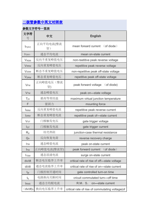
二极管参数中英文对照表
Cj Junction Capacitance 结电容ηV Rectification Efficiency 整流效率If DC Forward Current 正向直流电流I(AV) Average Forward Rectified Current 正向平均整流电流ID Stand-off Reverse Leakage Current 关态反向漏电流IFSM Peak Forward Surge Current 正向浪涌峰植电流ITSM Non Repetitive Surge Peak on-state Current 不重复浪涌峰值开态电流IDM Maximum Reverse Leakage 最大反向漏电流IFRM Repetitive Peak Forward Current 正向重复峰值电流IH Holding Current 维持电流IO Mean Forward Current 正向平均电流IR Reverse Leakage Current 反向漏电流Irr Reverse Recovery Current 反向恢复电流IPPM Maximum peak lmpulse Current 最大脉冲峰值电流IRM Maximum peak Reverse Current 最大峰值反向电流IRM(REC) Maximum peak Reverse recovery Current 最大峰值反向恢复电流IRSM Maximum Non-repetitive recovery Peak Current 最大峰值反向恢复电流IT On-state Test Current 导通测试电流I2t Rating for fusing 正向浪涌电流的平方对电流浪涌持续时间的积分值PM(AV)Maximum Steady State Power Dissipation 最大稳态功耗PPM Peak Pulse Power Dissipation 峰值脉冲功耗Ptot Total Power Dissipation 总功耗Qrr Recovered Charge 恢复电荷ROJA Thermal Resistance (Junction to Ambient)热阻(结到环境)ROJC Thermal Resistance(Junction to Case )热阻(结到管壳) ROJL Thermal Resistance(Junction to Lead )热阻(结到引线)TA Ambient Temperature 环境温度TC Case Temperature 管壳温度td Time Duration 持续时间tf Fall Time 下降时间Tj Junction Temperature 结温TL Lead Temperature 引线温度tfr Forward Recovery Time 正向恢复时间tr Rise Time 上升时间trr Reverse Recovery Time 反向恢复时间TSTG Storage Temperature 存储温度VBO Breakover Voltage 转折电压V(BR) Reverse Breakdown Voltage 反向击穿电压VF Instantaneous Forward Voltage 正向瞬态电压VFR Forward Recovery Voltage 正向恢复电压VDC,VR DC Reverse Voltage 反向直流电流VRM Maximum Reverse Paek Reverse Voltage 最大重复峰值反向电压VRMS RMS Input Voltage 均方根输入电压VRRM Peak Repetitive Reverse Voltage 反向重复峰值电压VWM Working Peak Reverse Voltage 反向工作峰值电压VC Clamping Voltage 箝位电压VWM Working Stand-off Voltage 关态工作电压VZ Zener Voltage 齐纳电压ZZ Dynamia Zener Impedance 动态齐纳阻抗αVF Temperature coefficient of forward voltage 正向压降的温度系数二极管电压参数及含义1)UTo:阈值电压。
分析仪器中英文对照表
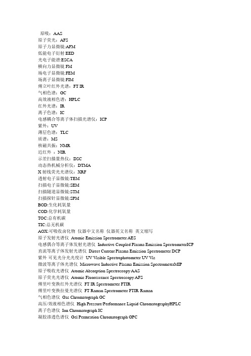
原吸:AAS原子荧光:AFS原子力显微镜:AFM低能电子衍射EED光电子能谱:ESCA横向力显微镜FM场电子显微镜:FEM场离子显微镜:FIM傅立叶红外光谱:FT-IR气相色谱:GC高效液相色谱:HPLC红外光谱:IR离子色谱:IC电感耦合等离子体扫描光谱仪:ICP紫外:UV薄层色谱:TLC质谱:MS核磁共振:NMR近红外:NIR示差扫描量热仪:DSC动态热机械分析仪:DTMAX射线荧光光谱仪:XRF透射电子显微镜:TEM扫描电子显微镜:SEM扫描隧道显微镜:STM扫描探针显微镜:SPMBOD:生化耗氧量COD:化学耗氧量TOC:总有机碳TIC:总无机碳AOX:可吸收卤化物仪器中文名称仪器英文名称英文缩写原子发射光谱仪Atomic Emission Spectrometer AES电感偶合等离子体发射光谱仪Inductive Coupled Plasma Emission SpectrometerICP 直流等离子体发射光谱仪Direct Current Plasma Emission Spectrometer DCP紫外-可见光分光光度计UV-Visible Spectrophotometer UV-Vis微波等离子体光谱仪Microwave Inductive Plasma Emission SpectrometerMIP原子吸收光谱仪Atomic Absorption Spectroscopy AAS原子荧光光谱仪Atomic Fluorescence Spectroscopy AFS傅里叶变换红外光谱仪FT-IR Spectrometer FTIR傅里叶变换拉曼光谱仪FT-Raman Spectrometer FTIR-Raman气相色谱仪Gas Chromatograph GC高压/效液相色谱仪High Pressure/Performance Liquid ChromatographyHPLC离子色谱仪Ion Chromatograph IC凝胶渗透色谱仪Gel Permeation Chromatograph GPC体积排阻色谱Size Exclusion Chromatograph SECX射线荧光光谱仪X-Ray Fluorescence Spectrometer XRFX射线衍射仪X-Ray Diffractomer XRD同位素X荧光光谱仪Isotope X-Ray Fluorescence Spectrometer电子能谱仪Electron Energy Disperse Spectroscopy能谱仪Energy Disperse Spectroscopy EDS质谱仪Mass Spectrometer MS核磁共振波谱仪Nuclear Magnetic Resonance Spectrometer NMR电子顺磁共振波谱仪Electron Paramagnetic Resonance Spectrometer ESR极谱仪Polarograph伏安仪Voltammerter动滴定仪Automatic Titrator电导仪Conductivity Meter水质分析仪Water Test Kits电泳仪Electrophoresis System表面科学Surface Science金属探测器Metal detectors检针机Needle detector machine电子显微镜Electro Microscopy光学显微镜Optical Microscopy金相显微镜Metallurgical Microscopy扫描探针显微镜Scanning Probe Microscopy表面分析仪Surface Analyzer无损检测仪Instrument for Nondestructive Testing物性分析Physical Property Analysis热分析仪Thermal Analyzer粘度计Viscometer流变仪Rheometer粒度分析仪Particle Size Analyzer热物理性能测定仪Thermal Physical Property Tester电性能测定仪Electrical Property Tester光学性能测定仪Optical Property Tester机械性能测定仪Mechanical Property Tester燃烧性能测定仪Combustion Property Tester老化性能测定仪Aging Property Tester生物技术分析Biochemical analysisPCR仪Instrument for Polymerase Chain Reaction PCRDNA及蛋白质的测序和合成仪Sequencers and Synthesizers for DNA and Protein 传感器Sensors其他Other/Miscellaneous流动分析与过程分析Flow Analytical and Process Analytical Chemistry气体分析Gas Analysis基本物理量测定Basic Physics样品处理Sample Handling部分收集器Fraction Collector氨基酸测序仪Protein Sequencer氨基酸组成分析仪Amino Acid Analyzer多肽合成仪Peptide synthesizerDNA测序仪DNA SequencersDNA合成仪DNA synthesizer金属/材料元素分析仪Metal/material elemental analysis 环境成分分析仪CHN Analysis发酵罐Fermenter生物反应器Bio-reactor摇床Shaker离心机Centrifuge电泳Electrophoresis酶标仪ELIASACO2培养箱CO2 Incubators倒置显微镜Inverted Microscope超净工作台Bechtop超声破碎仪Ultrasonic Cell Disruptor超低温冰箱Ultra-low Temperature Freezer恒温循环泵Constant Temperature Circulator超滤器Ultrahigh Purity Filter冻干机Freeze Drying Equipment紫外观察灯Ultraviolet Lamp分子杂交仪Hybridization OvenPCR仪PCR Amplifier化学发光仪Chemiluminescence Apparatus紫外检测仪Ultraviolet Detectorjhggjndhff888。
- 1、下载文档前请自行甄别文档内容的完整性,平台不提供额外的编辑、内容补充、找答案等附加服务。
- 2、"仅部分预览"的文档,不可在线预览部分如存在完整性等问题,可反馈申请退款(可完整预览的文档不适用该条件!)。
- 3、如文档侵犯您的权益,请联系客服反馈,我们会尽快为您处理(人工客服工作时间:9:00-18:30)。
1.内容范围1.1范围本规范涵盖表面粘合叠层垫片毛坯的要求。
1.2类别垫片应按合同或购买订单规定的下列成分,类型和等级生产(见6.2)成分:成分1—铝合金成分2—黄铜成分3—防腐蚀钢成分4—碳钢成分5—钛合金成分6—聚酰亚胺类型:类型Ⅰ全层叠式类型Ⅱ半层叠半固体式等级:等级1 0.002英寸层叠等级2 0.003英寸层叠2.适用性文件下列文件的发布自购买之日起生效,成为本规范的一部分。
除非有特殊文件规定,供应商可制定文件的后续修订版本。
若引用的文件已取消或无规定的替代文件,应使用最新出版的文件。
2.1 SAE出版物引用来自于SAE国际版,400 Commonwealth Drive,Warrendale,PA 15096-0001,电话:877-606-7323(美国和加拿大境内)或724-776-4970(美国境外),. AMS4900 钛片、带、板材,工业纯度,退火,55ksi(379 MPa)屈服强度AMS4901钛片、带、板材,工业纯度,退火,70.0ksi(485 MPa)AMS4902钛片、带、板材,工业纯度,退火,40.0ksi(276 MPa)屈服强度AMS4911钛合金、片、带、板材,6AI-4V,退火AMS4940钛片、带、板材,工业纯度,退火,25.0ksi(172 MPa)屈服强度AMS5513 耐腐蚀,钢片,带材,板材AMS5516耐腐蚀,钢片,带材,板材AMS5903 钢片、带、板材,耐腐蚀AMS5904钢片和带材,耐腐蚀AMS5905钢片和带材,耐腐蚀AMS5906钢片和带材,耐腐蚀AMS5910钢片、带、板材,耐腐蚀AMS5911钢片和带材,耐腐蚀AMS5912钢片和带材,耐腐蚀AMS5913钢片和带材,耐腐蚀AMS QQ-A-250/5铝合金镀铝2024,片材和板材AMS QQ-A-250/8 铝合金,5052,片材和板材2.2ASTM发行物引用来自于ASTM国际版,100 Barr Harbor Drive,P.O.Box C700, West Conshohocken ,PA19428-2959获取,电话:610-832-9598,.ASTM B 36 黄铜板,片材,带材和滚棒ASTM B 121 铅铜板,片材,带材和滚棒ASTM B 209 铝和铝合金片和板材ASTM B 601 铜和铜合金回火铭牌——锻造和铸造ASTM D 903 胶合粘接的剥离强度ASTM D 5213 用于电绝缘和电介质应用的聚合树脂薄膜2.3 ANSI发行物应用可从美国国家标准协会,25 West 43rd Street,纽约,NY 10036-8002获取,电话:212-642-4900,. ANSI/ASQC Z1.4 取样流程和属性检测表格2.4美国政府发行物应用可从DLA Document Services获取,Building 4/D,700 Robbins Avenue,Philadelphia,PA19111-5094,电话:(215)694-6396,http:///.QQ-S-698 钢,片和带,低碳MIL-I-24768/13 绝缘,塑料,分层,热固,棉-织物-基底。
酚醛-树脂(FBE)MIL-I-24768/15 绝缘,塑料,分层,热固,棉-织物-基底。
酚醛-树脂(FBE)3.要求3.1首样按合同或购买订单规定,层叠垫片生产样品的成分,类型,等级,公称尺寸以及侧向尺寸(参考1.2和3.2),应遵守首样检验规定(见4.3和6.3)3.1.1规格表单独的项目要求应遵守本文规定并符合适用的规格表.若本规范要求和规格表有冲突,以后者为准.3.2材料3.2.1层叠式和固体式毛坯料:3.2.1.1成分1层叠式应使用铝1100制造,符合ASTM B 209,合金1100(加工硬化状态为H19,最小拉伸强度为24.0ksi),或者铝合金5052制造,符合AMS QQ-A-250/8(加工硬化状态为H19或H39,最小拉伸强度为42.0ksi)3.2.1.1.1固体毛坯固体毛坯选用铝合金材料,使用ASTM B 209,合金1100层叠式时,符合AMS QQ-A-250/5(镀铝2024)T3,T4,T81或T861硬化状态;使用AMS QQ-A-250/8层叠式时,符合AMS QQ-A-250/8(5052)的H32或H34的硬化状态.层叠件和固体毛坯件应采用黄铜制造,符合ASTM B 36的UNS 26000标准或ASTM B 121的UNS C33500标准, H01退火或硬化(ASTM B 601).3.2.1.3成分3除非另有规定,层叠式和固体式毛坯应采用符合AMS5516,AMS5903,AMS5904,AMS5905,或AMS5906,标准的302型退火条件或者硬化处理方式的防腐蚀钢制造。
3.2.1.3.1类型304如果302型材料不能满足本规范的所有要求,使用304型代替302型,符合AMS5513,AMS5910,AMS5911,AMS5912,或AMS5913,退火条件或硬化处理方式的标准.3.2.1.4 成分4层叠件应由碳钢制造,符合QQ-S-698,回火退火或硬化处理.3.2.1.5.1固体毛坯固体毛坯应由钛合金片制造,符合AMS4911.3.2.1.6成分6层叠片应由聚酰亚胺制造,符合ASTM D 5213.3.2.1.6.1固体毛坯应由酚醛树脂棉织物做基底制造,符合MIL-I-24768/13或MIL-I-24768/15(类型为FBE或FBI状态)。
3.2.2剥离强度除非固体/叠层结合线较高,成分1到5的每一个层叠垫片的剥离强度不低于1磅每线性英寸以及不高于5磅每线性英寸。
对于成分6,除非固体/叠层结合线较高,每个垫圈叠层的剥离强度不低于1/2磅每线性英寸以及不高于2½磅每线性英寸。
3.3结构和尺寸垫片毛坯应根据本文规定的材料制作。
垫片适用的种类、等级和公称尺寸应符合表格1,适用的规格表,或其它要求.侧向尺寸应符合合同或采购订单成分5和6(见6.2和6.4).除非另有规定,对于成分1,2,3和4,侧向尺寸应符合规格表的规定或其它要求。
规范宽度和长度的公差应为1/8英寸.3.3.1结构内容叠层式和固体式毛坯的整个表面整体粘合,粘合面在不分离剩余叠层制件和固体毛坯的条件下允许剥离,以调整点垫片厚度。
毛坯垫圈应使用合适的工具切割,达到在正常处理的情况下保持原样,使其余的叠层不被分离。
3.3.2公称尺寸的公差公称尺寸的公差应符合表格2.3.3.3叠层厚度的公差等级1和2叠层垫片(见1.2)的厚度应分别为规定数值的±0.0002英寸和±0.0003英寸以内.3.3.4粘接厚度粘接厚度不应超过0.0003英寸.3.3.5零件编号识别如表格1所示的现有种类,等级和公称厚度并不能证明所有描述的产品均适用. 仅对规格表里所述的产品有特定的名称件号的产品适用.3.4浸水垫圈毛坯应该能够承受温度为120华氏度的全面浸水.3小时内不应有叠层的分离.3.5工艺毛坯垫圈应该在质量,清洁度保持一致,无瑕疵,符合材料的功能性能.4.检验4.1分类检查毛坯垫圈的检查应该分为:a.首件的检查(见4.2).b.质量一致性检查4.2首样检查首样检查应包括4.4规定的指定检查和4.3的附加检查.承包商应负责首样检查的工作(见6.3).4.2.1首样样品在签订合同之后和生产之前,承包商应尽快提交的首样样品.除非在合同或订单中另有规定,首样样品应包括2个1×12英寸的毛坯垫圈(见6.3).4.3首样试验4.3.1叠层分离在进行抗剥强度测试前,毛坯垫圈的样品垫圈条应在生产或成型后放置8小时,以先到为准,叠层剥离时应保持其余的部分不被分离.4.3.1.1叠层和结合的厚度在进行3.1规定的毛坯垫片的测试过程中,应进行尺寸的测量以确保符合3.3.3和3.3.4的各项标准.4.3.2抗剥强度抗剥离强度应根据ASTM D 903(见3.2.3).每份样品的剥离数量应符合表格3.4.3.3浸水按4.3.1规定的毛坯垫圈的样品条应在120℉±5的水中浸泡三个小时.测试结束后,应对毛坯垫片进行检查,以确保符合3.4的要求.4.4质量一致性检查4.4.1批次一个批次应包含所有在同等条件下生产的具有相同成分,类型,等级,公称尺寸和侧向尺寸的所有叠层垫片,在同一时间提交验收.4.4.2样品统计样品和检查应符合ANSI/ASQC Z1.4的一般要求.批次验收标准应基于单独的样品计划,并带有零位验收编号.4.4.3检验根据4.4.2选取的叠层垫片样品应进行目视和尺寸检验以判定是否符合本规范的要求.4.4.4材料检查用于生产叠层垫片的材料应经过符合各自的规范本文规定的检查和验收.合同商应提供需满足上述要求的标准.5.包装5.1包装对于购置目的,包装要求应在合同或购买订单中规定(见6.2).当实际包装材料由美国国防部人员负责时,这些人员必须联系负责的包装工厂以确定所需包装的要求。
(有关美国军方的包装要求就不继续翻译,用户可提出自己的要求)6.注意事项6.1目的用途本规范涵盖的表面叠层垫片毛坯可用于叠层垫片的生产.注意:边缘粘接的垫片只需符合成分,种类和等级要求,表面叠层结构在此不适用.6.2采集要求采集文件应做下列规定:a.本规范的标题,编号和日期,以及使用的规格表.b.叠层的成分/规范,材料的热处理或状态,或者:种类,等级和公称尺寸(见1.2,3.2.1和3.3);或从适用规格表单里选取的件号.c.垫片毛坯的尺寸(见3.3).d.数量e.包装要求(见5.1).f.是否需要首件(见3.1和6.3)g.样品计划(见4.4.1和4.4.2).6.3首样当要求做首样检测时,参与项目的应该是首样样品。
除非合同或采购订单中另有规定,首样应包括2个1×12英寸的毛坯垫圈。
签订合同中应包含安排检测、首样测试结果接受、首样处理的采集文件中的特别说明内容。
对于投标邀请,应提供对于早期政府做过测试的供货产品,政府保留放弃对其投标做首样检测权利的文件。
提供该产品的投标人,如果想依靠该产品或测试,必须提供投标证明表明政府的许可目前对正在执行的合同是适用的。
6.4 适用的侧面尺寸对一些垫圈毛坯适用的来自于工业毛坯的典型的侧面尺寸如表4所示。
表格1-结构和尺寸表格2-成分1,2,3,4,5和6的公差(厚度)表格3-剥离判定表格4-侧向尺寸。
