MMST6427-7;MMST6427-7-F;中文规格书,Datasheet资料
EE-SX1131 光传感器(透光)商品说明书

■DimensionsNote:All units are in millimeters unless otherwise indicated.■Features•Ultra-compact with a 5-mm-wide sensor and a 2-mm-wide slot.•PCB surface mounting type.•High resolution with a 0.3-mm-wide aperture.•Dual-channel output.■Absolute Maximum Ratings (Ta =25°C)Note:1.Refer to the temperature rating chart if the ambient temper-ature exceeds 25°C.2.Duty: 1/100; Pulse width: 0.1 msplete soldering within 10 seconds for reflow soldering and within 3 seconds for manual soldering.■Electrical and Optical Characteristics (Ta = 25°C)Internal CircuitTerminal No. Name A Anode NC Not connected.K Cathode C Collector E1 Emitter 1E2Emitter 2Recommended Soldering PatternCross section AAOptical axisUnless otherwise specified, the tolerances are ±0.15 mm.ItemSymbol Rated value EmitterForward current I F 25 mA(see note 1)Pulse forward cur-rentI FP 100 mA (see note 2)Reverse voltageV R 5 V DetectorCollector–Emitter voltageV CEO 20 V Emitter–Collector voltageV ECO 5 V Collector current I C 20 mA Collector dissipa-tionP C 75 mW (see note 1)Ambient tem-peratureOperating Topr –30°C to 85°C StorageTstg –40°C to 90°C Reflow soldering Tsol 255°C(see note 3)Manual solderingTsol350°C(see note 3)ItemSymbolValueConditionEmitterForward voltage V F 1.1 V typ., 1.3 V max.I F = 5 mA Reverse currentI R 10 μA max.V R = 5 V Peak emission wavelengthλP 940 nm typ.I F = 20 mADetectorLight current I L1/I L250 μA min., 150 μA typ., 500 μA max.I F = 5 mA, V CE = 5 V Dark current I D 100 nA max.V CE = 10 V, 0 l x Leakage currentI LEAK ------Collector–Emitter saturated voltage V CE (sat)0.1 V typ., 0.4 V max.I F = 20 mA, I L = 50 μA Peak spectral sensitivity wavelengthλP 900 nm typ.---Rising time tr 10 μs typ.V CC = 5 V, R L = 1 k Ω,I L = 100μAFalling timetf10 μs typ.V CC = 5 V, R L = 1 k Ω,I L = 100μABe sure to read Precautions on page 25.■Engineering DataForward Current vs. Collector Dissipation Temperature RatingForward Current vs. Forward Voltage Characteristics (Typical)Light Current vs. Forward Current Characteristics (Typical)Light Current vs. Collector −Emitter Voltage Characteristics (Typical)Relative Light Current vs. AmbientTemperature Characteristics (Typical)Response Time vs. Load Resistance Characteristics (Typical)Input OutputInputOutput90 %10 %Sensing Position Characteristics(Typical)Response Time Measurement CircuitSensing Position Characteristics (Typical)Distance d (mm)Distance d (mm)V CE = 2 VV CE = 10 VAmbient temperature Ta (°C)C o l l e c t o r d i s s i p a t i o n P C (m W )Forward voltage V F (V)F o r w a r d c u r r e n t I F (m A )F o r w a r d c u r r e n t I F (m A )Forward current I F (mA)L i g h t c u r r e n t I L (μA )Collector −Emitter voltage V CE (V)L i g h t c u r r e n t I L (μA )Ambient temperature Ta (°C)Load resistance R L (k Ω)T a = 25°C V CE = 5 VI F = 10 mA I F = 5 mAT a = 25°CI F = 5 mA V CE = 5 VI F = 5 mA V CE = 5 VTa = 25°CR e s p o n s e t i m e t r , t f (μs )R e l a t i v e l i g h t c u r r e n t I L (%)D a r k c u r r e n t I D (n A )R e l a t i v e l i g h t c u r r e n t I L (%)Ambient temperature Ta (°C)R e l a t i v e l i g h t c u r r e n t I L (%)I F = 5 mA V CE = 5 VTa = 25°CDark Current vs. Ambient Tem-perature Characteristics (Typical)V CC = 5 VUnit: mm (inch)■Tape and Reel ReelTapeTape configuration Tape quantity2,000 pcs./reel21±0.8 dia.2±0.513±0.5 dia.80±1 dia.330±2 dia.12.4+2018.4 max.Product nameQuantityLot number1.5 dia.Terminating part(40 mm min.)Pull-out directionEmpty(40 mm min.)Parts mounted Leading part(400 mm min.)Precautions■Soldering InformationReflow soldering•The following soldering paste is recommended:Melting temperature: 216 to 220°C Composition: Sn 3.5 Ag 0.75 Cu•The recommended thickness of the metal mask for screen printing is between 0.2 and 0.25 mm.•Set the reflow oven so that the temperature profile shown in the following chart is obtained for the upper surface of the product being soldered.Manual soldering•Use ”Sn 60” (60% tin and 40% lead) or solder with silver content.•Use a soldering iron of less than 25 W, and keep the temperature of the iron tip at 300°C or below.•Solder each point for a maximum of three seconds.•After soldering, allow the product to return to room temperature before handling it.StorageTo protect the product from the effects of humidity until the package is opened, dry-box storage is recommended. If this is not possible, store the product under the following conditions:Temperature: 10 to 30°C Humidity: 60% max.The product is packed in a humidity-proof envelope. Reflow soldering must be done within 48 hours after opening the envelope, during which time the product must be stored under 30°C at 80% maximum humidity.If it is necessary to store the product after opening the envelope, use dry-box storage or reseal the envelope.BakingIf a product has remained packed in a humidity-proof envelope for six months or more, or if more than 48 hours have lapsed since the envelope was opened, bake the product under the following conditions before use:Reel: 60°C for 24 hours or more Bulk: 80°C for 4 hours or more。
gfs4400中文说明书

gfs4400中文说明书概述:Gryphon GFS4400 2D固定式二维影像条码扫描模块提供给用户一个完全独立的OEM使用解决方案,它易于集成到自助服务一体机、核价器、售票、文档处理和医学实验室应用,以及自助售货机和其他自动设备中。
易于集成的设计理念,让Gryphon GFS4400 2D扫描模块为系统设计者提供了一个‘即插即用’的解决方案。
采用抗高冲击树脂构造,经得起溶剂和消毒液反复清洗,同时密封外壳符合工业标准,防水防尘,提供可靠的扫描性能。
GFS4400 2D OEM扫描模块凭借出色的近距离扫描特性,广角视野,高移动耐受性,快速阅读,在解码以及读取受损条码方面为用户提供了卓越的性能。
与所有Gryphon扫描器相同,GFS4400扫描模块拥有Datalogic得利捷的‘绿点’技术,提供有效的读取反馈。
因为GFS4400 OEM扫描模块深红色的稳定照明光线,使得用户的使用舒适度更佳。
与竞争产品闪烁的光线相比,对眼睛来说更易分辨,同时高可见度的4点瞄准器定义了一个精确的阅读区域,可减少意外读取的次数。
瞄准器的中心十字在多条码的环境下,为目标条码进行了定位。
GFS4400 OEM扫描模块,针对类似邮政码、PDF417这样的堆叠码和复合码等的一维和二维条码,可提供快速读取性能。
对移动营销或票务应用而言,这款影像式扫描模块同样能在读取移动设备上的条码时表现出卓越的性能。
采集签名以及扫描文件需要单独设备来完成,但是有了GFS4400 OEM扫描模块之后,这些单独设备便不再需要了。
GFS4400 OEM扫描模块中有几种触发模式可供使用。
首先,该扫描模块可自动感测物体并自动触发。
还有一种连续扫描模式,可在条码通过其视野范围时自动扫描并传输数据。
另外也可以通过可编程序逻辑控制器(PLC)或从传感器外部远程触发。
GFS4400 OEM扫描模块有支持RS-232串口的GFS4450-9型号和支持USB接口的GFS4470型号。
超米特电子有限公司产品说明书

1US Headquarters TEL +(1) 781-935-4850FAX +(1) 781-933-4318 • Europe TEL +(44) 1628 404000FAX +(44) 1628 404090Asia Pacific TEL +(852) 2 428 8008FAX +(852) 2 423 8253South America TEL +(55) 11 3917 1099FAX +(55) 11 3917 0817Superior elongation and tensilestrength help to prevent tearing in use due to mishandling. Typical properties for CHO-SEAL 1310 and 1273 materi-al are shown on pages 33 and 32respectively.High Shielding PerformanceCHO-SEAL 1310 material provides more than 80 dB of shielding effectiv-ness from 100 MHz to 10 GHz, while CHO-SEAL 1273 material provides more than 100 dB.Low Volume ResistivityBoth materials have exceptionally low volume resistivity, which makes them well suited for grounding appli-cations in which a flexible electrical contact is needed.Low Compression GasketSpacer gaskets are typicallydesigned to function under low deflec-tion forces. Chomerics uses design tools such as Finite Element Analysis (FEA) to accurately predict compres-sion-deflection behavior of various cross section options. Refer to page16.LCP Plastic SpacerLiquid crystal polymer (LCP)spacers, including those made with Vectra A130 material, provide aCHO-SEAL ®1310 or 1273Conductive ElastomersWith EMI spacer gaskets, shielding and grounding are provided by Chomerics’CHO-SEAL 1310 and 1273 conductive elastomers, specifi-cally formulated for custom shape molded parts. They provide excellent shielding and isolation against electro-magnetic interference (EMI), or act as a low impedance ground path between PCB traces and shielding media. Physically tough, these elas-tomers minimize the risk of gasket damage, in contrast to thin-walled extrusions or unsupported molded gaskets.Silicone-based CHO-SEAL 1310and 1273 materials offer excellent resistance to compression set over a wide temperature range, resulting in years of continuous service. CHO-SEAL 1310 material is filled with silver-plated-glass particles, while 1273 utilizes silver-plated-copper filler to provide higher levels of EMI shielding effectiveness.EMI Spacer GasketsThe unique design of Chomerics’EMI spacer gaskets features a thin plastic retainer frame onto which a conductive elastomer is molded. The elastomer can be located inside or outside the retainer frame, as well as on its top and bottom surface. EMI spacer gaskets provide a newapproach to designing EMI gaskets into handheld electronics such as dig-ital cellular phones. Board-to-board spacing is custom designed to fit broad application needs. Customized cross sections and spacer shapes allow for very low closure forcerequirements and a perfect fit in any design or device.Robotic InstallationSpacer gaskets can be installed quickly by robotic application. Integral locater pins in the plastic spacer help ensure accuratepositioning in both manual and pick-and-place assembly. Benefits include faster assembly and lower labor costs.The integrated conductive elastomer/plastic spacer gasket is a low cost,easily installed system for providing EMI shielding and grounding in small electronic enclosures.Figure 1Single Piece EMI Gasket/Locator PinsCHO-SEAL 1310 or 1273 Conductive Elastomer (Inside)Plastic Spacer Around Outsideor InsideApplications for EMI Spacer GasketsThe spacer gasket concept is especially suited to digital and dual board telephone handsets or other handheld electronic devices. It provides a low impedance path between peripheral ground traces on printed circuit boards and components such as:•the conductive coating on a plastic housing•another printed circuit board •the keypad assemblyTypical applications for EMI spacer gaskets include:•Digital cellular, handyphone and personal communications services (PCS) handsets •PCMCIA cards•Global Positioning Systems (GPS)•Radio receivers•Other handheld electronics, e.g.,personal digital assistants (PDAs)•Replacements for metal EMI shield-ing “fences” on printedcircuit boards in wireless tele-communications devicesstable platform for direct, highprecision molding of conductive elas-tomers. The Vectra A130 material described in Table 1 has excellent heat deflection temperature character-istics (489°F, 254°C). For weight con-siderations, the LCP has aspecific gravity of only 1.61. This plas-tic is also 100% recyclable.Typical EMI Spacer Gasket Design ParametersThe EMI spacer gasket concept can be considered using the design parameters shown in Table 2. Some typical spacer gasket profiles are shown below.Figure 2Typical Spacer Gasket Profiles3US Headquarters TEL +(1) 781-935-4850FAX +(1) 781-933-4318 • Europe TEL +(44) 1628 404000FAX +(44) 1628 404090Asia Pacific TEL +(852) 2 428 8008FAX +(852) 2 423 8253South America TEL +(55) 11 3917 1099FAX +(55) 11 3917 0817Finite Element AnalysisChomerics, a division of the Parker Hannifin Corporation’s Seal Group, is the headquarters of Parker Seal’s Elastomer Simulation Group. This unit specializes in elastomer finite element analysis (FEA) using MARC K6 series software as a foundation for FEA capability.Benefits of FEA include:•Quickly optimizing elastomer gasket designs•Allowing accurate predictions of alternate elastomer design concepts •Eliminating extensive trial and error prototype evaluationTypical use of FEA in EMI spacer gasket designs is to evaluate the force vs. deflection requirements of alternate designs.For example, onespacer design features a continuous bead of con-ductive elastomer molded onto a plastic spacer. An alternative designemploys an “interrupted bead,” where the interrup-tions (gaps left on the plastic frame) are sized to maintain the requiredlevel of EMI shielding. Figure 4illustrates these alternative designs.Gasket DeflectionFigure 5 compares the effect of continuous and interrupted elastomer gasket designs in terms of the force required to deflect the conductive elastomer. This actual cellular handset application required a spacer gasket with interrupted bead to meet desired deflection forces.Chomerics Designand Application ServicesChomerics will custom design a spacer for your application. Advice,analysis and design assistance will be provided by Chomerics Applications and Design engineers at no additional fee. Contact Chomerics directlyat the locations listed at the bottom of the page.Figure 3FEA Example of an EMISpacer Gasket Cross SectionFigure 4Continuous (top) and InterruptedElastomer GasketsFigure 5Typical Spacer Gasket Deflection。
YAMAHA IMX644 OWNER'S MANUAL
HM-TD5537T-7 W热成像热与光双谱网络小型定位系统商品说明书
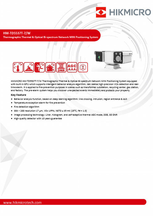
HM-TD5537T-7/WThermographic Thermal & Optical Bi-spectrum Network MINI Positioning SystemHIKMICRO HM-TD5537T-7/W Thermographic Thermal & Optical Bi-spectrum Network MINI Positioning System equipped with built-in GPU which supports intelligent behavior analysis algorithm, can realize high-precision VCA detection and real-time alarm. It is applied to fire-prevention purposes in scenes such as transformer substation, recycling center, gas station, and factory. The pre-alarm system helps you discover unexpected events immediately and protects your property.Key Feature●Behavior analysis function, based on deep learning algorithm: line crossing, intrusion, region entrance & exit●Temperature exception alarm for fire prevention●Fire detection algorithm●384 × 288 resolution 17 μm, VOx UFPA, NETD ≤ 35 mK (25°C, F# = 1.0)●Image processing technology: Liner, histogram, and self-adaptive thermal AGC mode, DDE, 3D DNR●High quality detector with 10 years guaranteeSpecificationThermal ModuleImage Sensor Vanadium Oxide Uncooled Focal Plane ArraysResolution 384 × 288Pixel Pitch 17 μmSpectral Range 8 μm to 14 μmNETD ≤ 35 mK (25 °C, F# = 1.0)Focal Length 6.3 mmIFOV 2.7 mradAperture F1.0Field of View 54.8° × 42.5° (H × V)Min. Focusing Distance 0.6 mDigital Zoom × 2, × 4, × 8Optical ModuleImage Sensor 1/2.8" Progressive Scan CMOSResolution 2688 × 1520, 4 MPMin. Illumination Color: 0.05 Lux @ (F1.6, AGC ON), B/W: 0.01 Lux @ (F1.6, AGC ON)Field of View 58.4° × 33.8° (H × V) to 2.14° × 1.2° (H × V)Focal Length 4.8 mm to 153 mm, 32 ×Aperture (Range) F1.2 to F4.4Focus Mode Semi-auto, manualDigital Zoom × 2, × 4, × 8, × 16Shutter Speed 1 s to 1/100,000 sWDR 120 dBOptical Defog YesImage EffectPicture in Picture Display partial image of thermal channel on the full screen of optical channel Target Coloration Yes. Supported in white hot and black hot mode.PTZMovement Range Pan: 360° Continuous Rotate; Tilt: From -90° to +90° (auto flip)Pan Speed Configurable, From 0.5°/s to 90°/sTilt Speed Configurable, From 0.5°/s to 40°/sProportional Zoom YesPresets 300Patrol Scan 8 patrols; Up to 32 presets per patrolPower Off Memory YesPark Preset/Patrol Scan/Auto Scan/Tilt Scan/Random Scan/Frame Scan/Panorama Scan PT Status Turn On/Turn OffScheduled Task Preset/Patrol Scan/Auto Scan/Tilt Scan/Random Scan/Frame Scan/Panorama Scan/Dome Reboot/Dome Adjust/Aux OutputIlluminatorIR Distance Up to 30 mIR Intensity and Angle Automatically adjustedSmart FunctionVCA 4 VCA rule types (line crossing, intrusion, region entrance, and region exiting), 10 scenes and 8 VCA rules for each scene.Temperature Measurement 3 temperature measurement rule types, 273 presets as scene, 21 rules of each scene (10 points, 10 areas, and 1 line)Temperature Range -20°C to 550°C (-4°F to 1022°F) Temperature Accuracy Max. (± 2°C, ± 2%)Fire Detection Dynamic fire and smoke detection, up to 10 fire points and 10 smoke points detectable.Video and AudioMain Stream Optical channel50 Hz: 25 fps (2688 × 1520, 1920 × 1080, 1280 × 960, 1280 × 720)60 Hz: 30 fps (2688 × 1520, 1920 × 1080, 1280 × 960, 1280 × 720)Thermal channel50 fps (1920 × 1080, 1280 × 960, 1280 × 720, 704 × 576, 640 × 512, 384 × 288)Sub-stream Optical channel50 Hz: 25fps (704 × 576, 352 × 288)60 Hz: 30 fps (704 × 576, 352 × 288) Thermal channel50 fps (704 × 576, 640 × 512, 384 × 288)Video Compression Main stream: H.265+/H.265/H.264+/ H.264 Sub-stream: H.265/H.264/MJPEGAudio Compression G.711alaw/G.711ulaw/G.722.1/G.726/MP2L2/AAC/PCM NetworkProtocols IPv4/IPv6, HTTP, HTTPS, 802.1x, Qos, FTP, SMTP, UPnP, SNMP, DNS, DDNS, NTP, RTSP, RTCP, RTP, TCP, UDP, IGMP, ICMP, DHCP, PPPoENetwork Storage MicroSD/SDHC/SDXC card (up to 128 GB) local storage, and NAS (NFS, SMB/CIFS), auto network replenishment (ANR)API ISAPI, HIKVISION SDK, third-party management platform, ONVIF (Profile S, Profile G, Profile T)Simultaneous Live View Up to 20 channelsUser/Host level Up to 32 users. 3 levels: administrator, operator, userSecurity User authentication (ID and Password), MAC address binding, HTTPS encryption, IEEE 802.1x (EAP-MD5, EAP-TLS), access control, IP address filteringClient iVMS-4200, Hik-ConnectWeb Browser Live view (plug-in allowed): Internet Explorer 11 Live view (plug-in free): Chrome 57.0 +, Firefox 52.0 + Local service: Chrome 57.0 +, Firefox 52.0 +InterfaceAlarm Input 2-ch inputs (0 to 5 VDC)Alarm Output 2-ch relay outputs, alarm response actions configurableAlarm Action Preset/patrol scan/SD card record/relay output/smart capture/FTP upload/email linkageAudio Input 1 Audio Output 1Communication Interface 1, RJ45 10 M/100 M self-adaptive Ethernet interface. 1, RS-485 interfaceGeneralMenu Language 32 languagesEnglish, Russian, Estonian, Bulgarian, Hungarian, Greek, German, Italian, Czech, Slovak, French, Polish, Dutch, Portuguese, Spanish, Romanian, Danish, Swedish, Norwegian, Finnish, Croatian, Slovenian, Serbian, Turkish, Korean, Traditional Chinese, Thai, Vietnamese, Japanese, Latvian, Lithuanian, Portuguese (Brazil)Power Supply 24 VDC Power Consumption 20 WWorking Temperature/Humidity -40°C to 70°C (-40°F to 158°F) 90% or lessWiper YesProtection Level IP67 StandardTVS 6000V lightning protection, surge protection, voltage transient protectionDimensions 321 mm × 194 mm × 153 mm (12.64" × 7.64" × 6.02") Weight Approx. 4.8 kg (10.582 lb)DRI Range Table* The table is only for reference and the performance may vary according to different environment.* The optimal detection, recognition, and identification distances are calculated according to Johnson’s Criteria.Detection Range: In order to distinguish an object from the background, the object must be covered by 1.5 or more pixels. Recognition Range: In order to classify the object (animal, human, vehicle, etc.), the object must be covered by 6 or more pixels.Identification Range: In order to identify the object and describe it in details, the object must be covered by 12 or more pixels..Detection Range (Vehicles: 1.4 × 4.0 m) Detection Range (Humans: 1.8 × 0.5 m) Recognition Range (Vehicles: 1.4 × 4.0 m) Recognition Range (Humans: 1.8 × 0.5 m) Identification Range (Vehicles: 1.4 × 4.0 m) Identification Range (Humans: 1.8 × 0.5 m) 568 m185 m142 m46 m71 m23 mSmart Function Table* The table is only for reference and the performance may vary according to different environment.VCA Range(Vehicles: 1.4 × 4.0 m) VCA Range (Humans: 1.8 × 0.5 m) Temperature Measurement (Object: 2 × 2 m) Temperature Measurement (Object: 1 × 1 m) Fire Detection (Object: 2 × 2 m) Fire Detection (Object: 1 × 1 m) 132 m44 m 148 m 74 m371 m185 mAvailable Model HM-TD5537T-7/WDimensionCOMPLIANCE NOTICE: The thermal series products might be subject to export controls in various countries or regions, including without limitation, the United States, European Union, United Kingdom and/or other member countries of the Wassenaar Arrangement. Please consult your professional legal or compliance expert or local government authorities for any necessary export license requirements if you intend to transfer, export, re-export the thermal series products between different countries.。
多参数监护仪产品技术要求中微泽

2.性能指标2.1安全应符合GB 9706.1-2007《医用电气设备第1 部分:安全通用要求》、GB 9706.25-2005《医用电气设备第2-27 部分:心电监护设备安全专用要求》、YY 0667-2008 《自动循环无创血压监护设备的安全和基本性能专用要求》、YY 0668-2008《医用电气设备第 2 部分:多参数患者监护设备安全专用要求》、YY 0709-2009《医用电气设备第 1-8 部分:安全通用要求并列标准:通用要求,医用电气设备和医用电气系统中报警系统的测试和指南》的要求,产品特性见附录A。
2.2标签要求2.2.1设备标记2.2.1.1产品特性识别应符合 YY1079-2008《心电监护仪》标准中 4.1.1.1 的要求。
面板控制和开关应符合 YY1079-2008《心电监护仪》标准中 4.1.1.2 的要求。
2.2.1.2警告和告诫应符合 YY1079-2008 标准中 4.1.1.4 的要求。
2.2.2操作者手册2.2.2.1性能参数公布应符合 YY1079-2008 标准中 4.1.2.1 的要求。
内置充电电池工作时间的要求见表 2。
表 2 内置充电电池工作时间2.2.2.2使用注意事项应符合 YY1079-2008 标准中 4.1.2.2 的要求。
2.2.3维修手册应符合YY1079-2008标准中4.1.3的要求。
2.2.4起搏器脉冲抑制能力2.2.4.1无过冲起搏器脉冲抑制应符合YY1079-2008标准中4.1.4.1的要求。
2.2.4.2有过冲起搏器脉冲抑制应符合YY1079-2008标准中4.1.4.2的要求。
2.2.4.3起搏脉冲检测器对快速心电图信号的抑制应符合YY1079-2008标准中4.1.4.3的要求。
2.2.4.4起搏脉冲检测器失效应符合YY1079-2008标准中4.1.4.5的要求。
2.3监护仪的性能要求2.3.1心电参数2.3.1.1工作条件:见本产品技术要求 3.0 的要求。
矽普特产品简介
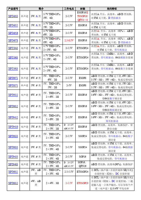
XPT5983 XPT9971 XPT8871 XPT9812
XPT9612
XPT9412 XPT9410 XPT9833
XPT9633 XPT9433 XPT9403 XPT6011
XPT6012
道(双声道)提供4W 平均功率
产品型号 XPT6013 XPT6871 XPT6875 XPT4809
XPT9863
XPT8863
XPT2008
XPT2069
XPT2068 C
XPT4098 XPT4871
F XPT4890 XPT4990 XPT0030 XPT4066 XPT4088 XPT4068 XPT6872
4 SOP18/SS OP24/SOP
16
SOP16/QF N16/DIP16 MSOP8/SO P8/ESOP8/
DFN8 MSOP8/SO
P8/DFN
WCSP9
MSOP8/ES OP8/SOP8/
DFN
WCSP
备注 单端模式,5V,THD+N≤0.5%,75mW (32Ω)。XPT4963的 SD 是高电平工作,
封装
ETSSOP20
SOP8
ESOP8
MSOP8/SO P8
SOP16/DIP 16/ETSSO P16/ETSS OP20 SOP16/ET SSOP20/DI P16
SOP8/ ESOP8
SOP16/DIP 16/ESOP16
SOP16/ES OP16/DIP1
6
QFN16/SO P16/DIP16
完全兼容 LM4861/8002 ,XPT4871H
Datasheet MLX90614 中文 数据手册 rev008
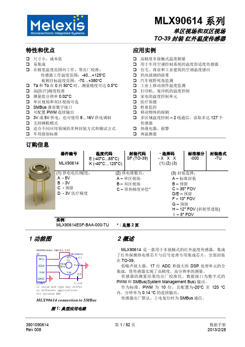
10-位 PWM 输出模式是连续输出所测物体温度的标准配置,测量物体的温度范围为-20…120 °C,分辨 率为 0.14 °C。PWM 通过修改 EEPROM 内 2 个单元的值,实际上可以根据需求调整至任何温度范围,而这对 出厂校准结果并无影响。
传感器的测量结果均出厂校准化,数据接口为数字式的 PWM 和 SMBus(System Management Bus) 输出。
作为标准,PWM 为 10 位,且配置为-20˚C 至 120 ˚C 内,分辨率为 0.14 ˚C 的连续输出。
传感器出厂默认,上电复位时为 SMBus 通信。
3901090614 Rev 008
PWM 引脚也可配置为热继电器(输入是 To),这样可以实现简单且性价比高的恒温控制器或温度报警(冰 点/沸点)应用,其中的温度临界值是用户可编程的。在 SMBus 系统里,这个功能可以作为处理器的中断信号, 以此触发读取主线上从动器的值,并确定精度条件。
传感器有两种供电电压选择:5V 或 3V(电池供电)。其中,5V 也可简便的从更高供电电压(例如 8 至 16V)上通过外接元件调制。(具体请参考“应用信息”)
MLX90614 connection to SMBus
图 1: 典型应用电路
2 概述
MLX90614 是一款用于非接触式的红外温度传感器,集成 了红外探测热电堆芯片与信号处理专用集成芯片,全部封装 在 TO-39。
低噪声放大器、17 位 ADC 和强大的 DSP 处理单元的全 集成,使传感器实现了高精度,高分辨率的测量。
(电话局电码化器材)技术规格书-资料
********工程物资采购招标设备名称:电码化器材技术规格书设计院二0 年月1. 概述1.1 适用范围本规格书是对适用于****年***信号设备大修改造工程***线***局管内***、***、***、***共4站站内电码化发送柜、综合柜、发送器、发送监测器、室内外配套设备器材(感容盒HLC、匹配盒HBP(含BVB防雷)、电码化匹配变压器及防雷组合、股道电码化匹配变压器及防雷组合、电码化电阻组合)的有关规定,并作为卖方制定技术建议书的依据。
1.2 招标范围招标范围为****年***信号设备大修改造工程******线***局管内***、***、***、***共*站站内电码化发送柜、综合柜、发送器、发送监测器、室内外配套设备器材(感容盒HLC、匹配盒HBP(含BVB 防雷)、电码化匹配变压器及防雷组合、股道电码化匹配变压器及防雷组合、电码化电阻组合)。
1.3 需求一览表:2. 技术规格2.1电码化器材在下列环境下应可靠地工作:⑴.周围空气温度:-40℃~+60℃;⑵.空气相对湿度:不大于90% (温度25℃);⑶.大气压力:74.8~106kPa(海拔高度相当于2500m以下);⑷.振动频率:1~35Hz,加速度幅值为10m/s;。
⑸.周围无腐蚀和无引起爆炸危险的有害气体。
2.1.1站内电码化设备采用集中设置方式,即主体设备集中安放于车站信号设备室内。
2.1.2设备必须通过有资质的认证机构的认证和质量检测。
2.1.3主要技术指标:信号特征:移频标准载频频率:1700Hz、2000Hz、2300Hz和2600Hz,共四种,其中1700Hz、2300Hz交替用于区间的下行线及站内的下行运行方向,而2000Hz、2600Hz则交替用于区间的上行线及站内的上行运行方向;频偏:△f=±11Hz;偏差:载频的偏差小于或等于±1.5Hz,低频小于或等于±0.03 Hz;调制信号频率(即低频信息):10.3 Hz、11.4 Hz、12.5 Hz、13.6 Hz、14.7 Hz、15.8 Hz、16.9 Hz、18 Hz、19.1 Hz、20.2 Hz、21.3 Hz、22.4 Hz、23.5 Hz、24.6 Hz、25.7 Hz、26.8 Hz、27.9 Hz及29 Hz共18个;2.1.4 设备在下列条件下应能正常工作:室外环境温度:-30℃~+70℃,室内环境温度为-5℃~+40℃;相对湿度不大于90%(温度25℃时);大气压力:74.8 ~ 106Kpa(海拔高度相当于2500m以下);周围无腐蚀和引起爆炸危险的有害气体;2.1.5设备必须工作可靠并符合“故障—安全”原则。
讯飞网维 信号特克 千兆以太网性能测试仪 说明书

SIGNAL TEK™Cable Performance T esterI Gigabit PerformanceQualification – Test toIEEE 802.3 standardsI Selectable PerformanceT esting – qualify performanceof Data, Voice over IP, andIP Video applicationsI Performs Gigabit Ethernetlink establishment test in10 secondsI Data Monitoring to detectintermittent network problemsI Smart Autotest Functiondetects the presence of theSIGNAL TEK remote, activenetwork device or open endedcable and automatically runsthe appropriate test suiteI Intuitive Graphical UserInterface for fast andeasy operationI Internal and USBData Storage –store 20,000 tests internallyor unlimited on USB driveI Prints Easy-to-Read Pass/Fail Qualification ReportsSIGNALTEK™– High-Performance Gigabit Ethernet TestingSIGNALTEK™is the most cost-effective Gigabit Ethernet cableAutotest key to initiate tests from the remote end for one personoperation2.8Љ(7.1cm) 1⁄4VGA Color Display with backlighting for use in low light conditionMulti-color LEDs indicate link status,loopback mode,10/100 and Gigabit device detection,Autotest pass/fail,and battery conditionEasy-to-navigate user interfaceCompact design and soft over-mold sides fit well into any sized handContext sensitive softkeysSingle button cable testingQuick navigation key returns to Job Manager screenSingle button push for active network testing and monitoring Port status function detects 10/100 or Gigabit Ethernet devicesDisplays result for last autotest via red or green LED indicationSIGNAL TEK ™Standard KitCatalog No. 33-974I1 SIGNALTEK ™Near-end and remote-end handset IDEAL INDUSTRIES, INC.03/06Printed in U.S.A.ISO 9001:2000 QMSNo. 33-974SIGNALTEK ™OptionalPower Adapter – 4010-00-0136DESCRIPTION CAT NUMBER SIGNALTEK™ Cable Performance Tester 33-974Replacement cable accessory kit –Contains all original cables in SIGNALTEK™ kit 1219-91-0003RJ45 to 8 head alligator clipK-7920OPTIONALUniversal (120-240V) AC-DC power adapter (1)4010-00-0136。
OTP6200用户手册V1.00
5.2 安装或升级应用程序................................................................................. 9 5.3 插入或取出测试模块...............................................................................10
6 设置设备..........................................................................................14
6.1 重新校准触摸屏.......................................................................................14 6.2 调整音量.................................................................................................. 14 6.3 设置日期和时间格式...............................................................................15 6.4 选择操作语言...........................................................................................17 6.5 调整背光.................................................................................................. 18 6.6 软件自恢复.............................................................................................. 18 6.7 远程控制.................................................................................................. 19 6.8 设置 IP 地址.............................................................................................20 6.9 PING 测试.................................................................................................21
光纤光栅解调仪技术规格书

光纤光栅解调仪技术规格书一、设备用途简介光纤压力调制解调仪是井下F-P腔压力传感器的地面配套解调设备,通过接收和解调压力传感器反射回来的光谱信号,实现对井下单点温度、压力数据的监测。
二、主要技术指标1.有效测量深度:不小于4km;2.通道个数:12个;3.压力测量范围:0—50MPa;4.压力测量精度:0.1% F.S,且小于0.2MPa;5.温度测量范围:0—300℃;6.温度测量精度:0.5℃;7.单通道压力测量速率:不大于10s/次;8.单通道温度测量速率:不大于10s/次;9.配套光纤规格:单模光纤;10.端口跳线接头类型:E2000或PC/APC;11.数据存储格式:.CSV格式;12.数据存储方式:每个通道每日形成一个文件,每月形成一个文件夹且数据存储格式固定,便于导入oracle数据库;13.硬盘空间:不小于500GB;14.工作环境温度:-20℃至50℃环境下能够连续正常工作;15.工作环境湿度:空气相对湿度不大于90%的环境下,连续正常工作;16.噪音:≤50dB;17.设备外形尺寸mm(长×宽×高):不大于500×500×150。
三、设备应具备的功能1.能够实时显示F—P腔光谱信号图;2.能够实时显示井下压力传感器温度、压力数据;3.能够显示压力、温度历史数据及温、压变化趋势;4.能够计算井下Sub_cool数值及显示其变化趋势。
四、产品执行标准SYT 6231-2006 压力传感系统性能检测实验GB/T 17626.2-2006 电磁兼容试验和测量技术静电放电抗扰度试验GB/T 17626.3-2006 电磁兼容试验和测量技术射频电磁场辐射抗扰度试验GB/T 17626.4-2008 电磁兼容试验和测量技术电快速瞬变脉冲抗扰度试验GB/T 17626.11-2008 电磁兼容试验和测量技术电压暂降短时中断和电压变化的抗扰度试验GB/T 2423.1-2008 电工电子产品环境试验第2部分:试验方法试验A:低温GB/T 2423.2-2008 电工电子产品环境试验第2部分:试验方法试验B:高温GB/T 2423.3-2006 电工电子产品环境试验第2部分:试验方法试验Ca:恒定湿热试验方法五、产品主要配置1.光纤测压主机一台2.光纤测压主机配套显示器(含鼠标、键盘)一台3.单模跳线及配套法兰(APC/PC或APC/E2000)十二根六、技术培训供方在设备安装完一周内负责对甲方操作人员、技术人员、设备维修人员进行技术培训,讲解设备的工作原理,介绍每个主要部件的用途及日常的维修、保养步骤,并能使操作人员独立操作设备,能有效掌握设备调整和故障排除的技术。
产品规格说明书(EW-DX SKM-S)
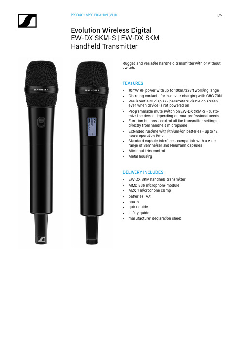
Handheld TransmitterDELIVERY INCLUDES• EW-DX SKM handheld transmitter • MMD 835 microphone module • MZQ 1 microphone clamp • batteries (AA)• pouch • quick guide • safety guide• manufacturer declaration sheetRugged and versatile handheld transmitter with or without switch.FEATURES• 10mW RF power with up to 100m/328ft working range • Charging contacts for in-device charging with CHG 70N • Persistent eInk display - parameters visible on screeneven when device is not powered on • Programmable mute switch on EW-DX SKM-S - custo-mize the device depending on your professional needs • Function buttons - control all the transmitter settingsdirectly from handheld microphone • Extended runtime with lithium-ion batteries - up to 12hours operation time • Standard capsule interface - compatible with a widerange of Sennheiser and Neumann capsules • Mic input trim control •Metal housingHandheld TransmitterSPECIFICATIONSEW-DX SKM (Handheld Transmitter)Input voltage 2.0 - 4.35 VInput current< 300 mAPower supply 2 AA batteries 1.5 V (al-kali manganese) or BA 70rechargeable battery packOccupied bandwidth200 kHzTransmit power (radiated)Audio link: 10 mW ERP(Range Y1-3: 12 mW ERP)LD mode: 10 mW ERPBLE: max. 10 mW EIRPDimensions (ø x l)(incl. MMD 835 microphone module)(without microphone module)50 x 268 mm (1.97" x 10.55")40 x 200 mm (1.57" x 7.87")Weight (without batteries) (incl. MMD 835 microphone module)(without microphone module)approx. 304 g (0.67 l bs) approx. 195 g (7.14 lbs)SystemAudio link frequency ranges Q1-9R1-9S1-10S2-10S4-10U1/5V3-4V5-7X1-6X9-18Y1-3470.2 - 550 MHz520 - 607.8 MHz606.2 - 693.8 MHz614.2 - 693.8 MHz630 - 693.8 MHz823.2 - 831.8 MHz &863.2 - 864.8 MHz925.2 - 937.3 MHz941.7 - 951.8 MHz &953.05 - 956.05 MHz &956.65 - 959.65 MHz1350.2 - 1398.8 MHz1435.2 - 1524.8 MHz1785.2 - 1799.8 MHzBluetooth® Low Energy(BLE) frequency range2402 - 2480 MHzAudio frequencyresponse20 Hz - 20 kHz (-3 dB)Audio THD≤ -60 dB for 1 kHz@ -3 dBfs input level Dynamic range134 dBSystem latency 1.9 msOperating temperature-10 °C - +55 °C(14 °F - 131 °F)Relative humidity 5 - 95 % (non-condensing)Handheld TransmitterPRODUCT VARIANTSEW-DX SKM-S (Q1-9)470.2 - 550 MHz Art. no. 509412 EW-DX SKM-S (R1-9)520 - 607.8 MHz Art. no. 509413 EW-DX SKM-S (S1-10)606.2 - 693.8 MHz Art. no. 509414 EW-DX SKM-S (S1/10)606.2 - 637.8 MHz & 650.2 - 693.8 MHz Art. no. 509415 EW-DX SKM-S (S2-10)614.2 - 693.8 MHz Art. no. 509417 EW-DX SKM-S (S4-10)630 - 693.8 MHz Art. no. 509418 EW-DX SKM-S (U1/5)823.2 - 831.8 MHz & 863.2 - 864.8 MHz Art. no. 509419 EW-DX SKM-S (V3-4)925.2 - 937.3 MHz Art. no. 509421 EW-DX SKM-S (V5-7)941.7 - 951.8 MHz & 953.05 - 956.05 MHz & 956.65 - 959.65 MHz Art. no. 509422 EW-DX SKM-S (X1-6)1350.2 - 1398.8 MHz Art. no. 509424 EW-DX SKM-S (X9-18)1435.2 - 1524.8 MHz Art. no. 509425 EW-DX SKM-S (Y1-3)1785.2 - 1799.8 MHz Art. no. 509423 EW-DX SKM (Q1-9)470.2 - 550 MHz Art. no. 509426 EW-DX SKM (R1-9)520 - 607.8 MHz Art. no. 509427 EW-DX SKM (S1-10)606.2 - 693.8 MHz Art. no. 509428 EW-DX SKM (S1/10)606.2 - 637.8 MHz & 650.2 - 693.8 MHz Art. no. 509429 EW-DX SKM (S2-10)614.2 - 693.8 MHz Art. no. 509431 EW-DX SKM (S4-10)630 - 693.8 MHz Art. no. 509432 EW-DX SKM (U1/5)823.2 - 831.8 MHz & 863.2 - 864.8 MHz Art. no. 509433 EW-DX SKM (V3-4)925.2 - 937.3 MHz Art. no. 509435 EW-DX SKM (V5-7)941.7 - 951.8 MHz & 953.05 - 956.05 MHz & 956.65 - 959.65 MHz Art. no. 509436 EW-DX SKM (X1-6)1350.2 - 1398.8 MHz Art. no. 509437 EW-DX SKM (X9-18)1435.2 - 1524.8 MHz Art. no. 509438 EW-DX SKM (Y1-3)1785.2 - 1799.8 MHz Art. no. 509439MICROPHONE COMPATIBILITYMicrophone modules compatible with the EW-DX SKM-S and EW-DX SKM handheld transmitters MMD 835-1Dynamic microphone module with cardioid polar patternMMD 845-1Dynamic microphone module with supercardioid polar patternMME 865-1Pre-polarized condenser microphone module with supercardioid polar patternMMD 935-1Dynamic microphone module with cardioid polar patternMMD 945-1Dynamic microphone module with supercardioid polar patternMMK 965-1Condenser microphone module with switchable cardioid and supercardioid polar pattern MMD 42-1Dynamic microphone module with omni-directional polar patternNeumann KK 204Condenser microphone module with cardioid polar patternNeumann KK 205Condenser microphone module with supercardioid polar patternMM 435Dynamic microphone module with cardioid polar patternMM 445Dynamic microphone module with supercardioid polar patternME 9002Pre-polarized condenser microphone module with omni-directional polar patternME 9004Pre-polarized condenser microphone module with cardioid polar patternME 9005Pre-polarized condenser microphone module with supercardioid polar patternHandheld TransmitterDIMENSIONS40.31.59Mikrofonmodul MMD835 - nur Beispiel microphon module MMD835 - example only341.34268.510.5750.51.99200.77.9156.56.16Handheld TransmitterSennheiser electronic GmbH & Co. KG · Am Labor 1 · 30900 Wedemark · Germany · EW-DX SKM handheld transmitterThe handheld transmitter shall be for use with a compa-nion receiver as part of a digital wireless RF transmission system.The handheld transmitter shall operate within the following UHF frequency ranges, with a switching bandwidth of up to 88 MHz: 470.2 – 550 MHz, 520 – 607.8 MHz, 606.2 – 693.8 MHz, 614.2 – 693.8 MHz, 630 – 693.8 MHz, 823.2 – 831.8 MHz, 863.2 – 846.8 MHz, 925.2 – 937.3 MHz, 941.7 – 951.8 MHz, 953.05 – 956.05 MHz, 956.65 – 959.65 MHz, 1350.2 – 1398.8 MHz, 1435.2 – 1524.8 MHz, 1785.2 – 1799.8 MHz. Different frequency variants shall be available depen-ding on country-specific regulations.The audio frequency response shall be between 20 Hz and 20 kHz (-3 dB). Audio total harmonic distortion (THD) shall be≤******************************************shall be 134 dB. System latency shall be 1.9 ms.Occupied bandwidth shall be 200 kHz. Transmit power (radiated) shall be 10 mW ERP (1785.2 – 1799.8 MHz Range: 12 mW ERP).The handheld transmitter shall be menu-driven with a backlit eInk display showing the relevant status informati-on such as frequency, battery status or AES 256 encrypti-on status.All transmitter parameters shall be adjustable with functi-on buttons on the device itself or by Bluetooth Low Energy (BLE) synchronization via the associated receiver. The fun-ction buttons shall be lockable against accidental misuse.Power shall be supplied to the handheld transmitter by two 1.5 V AA size batteries or by one Sennheiser BA 70 rechar-geable battery pack. Operating time shall be typically 12 hours with a battery pack and up to 8 hours with AA batteries.The handheld transmitter shall feature charging contacts for direct charging of the transmitter with inserted BA 70 battery pack in a Sennheiser CHG 70N network-enabled charger.The handheld transmitter shall utilize Sennheiser’s stan-dard capsule interface serving Sennheiser microphone modules of the evolution wireless and 2000 series and Digital 6000 and 9000 as well as the Neumann KK 204 / 205 microphone modules.The handheld transmitter shall have a rugged metalhousing; dimensions shall be approximately 50 mm (1.97“) in diameter and 268 mm (10.55“) in length including a Sennheiser MMD 835 microphone module. Weight inclu-ding MMD 835 microphone module shall be approximately 304 grams (0.67 lbs). Operating temperature shall range from −10 °C to +50 °C (+14 °F to +122 °F).The handheld transmitter shall be the Sennheiser EW-DX SKM.EW-DX SKM-S handheld transmitterThe handheld transmitter shall be for use with a compa-nion receiver as part of a digital wireless RF transmission system.The handheld transmitter shall operate within the following UHF frequency ranges, with a switching bandwidth of up to 88 MHz: 470.2 – 550 MHz, 520 – 607.8 MHz, 606.2 – 693.8 MHz, 614.2 – 693.8 MHz, 630 – 693.8 MHz, 823.2 – 831.8 MHz, 863.2 – 846.8 MHz, 925.2 – 937.3 MHz, 941.7 – 951.8 MHz, 953.05 – 956.05 MHz, 956.65 – 959.65 MHz, 1350.2 – 1398.8 MHz, 1435.2 – 1524.8 MHz, 1785.2 – 1799.8 MHz. Different frequency variants shall be available depen-ding on country-specific regulations.The audio frequency response shall be between 20 Hz and 20 kHz (-3 dB). Audio total harmonic distortion (THD) shall be≤******************************************shall be 134 dB. System latency shall be 1.9 ms.Occupied bandwidth shall be 200 kHz. Transmit power (radiated) shall be 10 mW ERP (1785.2 – 1799.8 MHz Range: 12 mW ERP).A programmable mute switch shall be provided for muting or unmuting either the audio signal or the radio signal. The mute switch can also be deactivated.The handheld transmitter shall be menu-driven with a backlit eInk display showing the relevant status informati-on such as frequency, battery status or AES 256 encrypti-on status.All transmitter parameters shall be adjustable with functi-on buttons on the device itself or by Bluetooth Low Energy (BLE) synchronization via the associated receiver. The fun-ction buttons shall be lockable against accidental misuse.Power shall be supplied to the handheld transmitter by two 1.5 V AA size batteries or by one Sennheiser BA 70 rechar-geable battery pack. Operating time shall be typically 12 hours with a battery pack and up to 8 hours with AA batteries.The handheld transmitter shall feature charging contacts for direct charging of the transmitter with inserted BA 70 battery pack in a Sennheiser CHG 70N network-enabled charger.The handheld transmitter shall utilize Sennheiser’s stan-dard capsule interface serving Sennheiser microphone modules of the evolution wireless and 2000 series and Digital 6000 and 9000 as well as the Neumann KK 204 / 205 microphone modules.The handheld transmitter shall have a rugged metalhousing; dimensions shall be approximately 50 mm (1.97“) in diameter and 268 mm (10.55“) in length including a Sennheiser MMD 835 microphone module. Weight inclu-ding MMD 835 microphone module shall be approximately 304 grams (0.67 lbs). Operating temperature shall range from −10 °C to +50 °C (+14 °F to +122 °F).The handheld transmitter shall be the Sennheiser EW-DX SKM-S.。
德律7710技术参数
德律7710技术参数
德律7710是一款高性能的通信系统,具有以下技术参数:
1. 支持2G、3G和4G网络制式,包括GSM、HSPA和LTE。
2. 支持多种频段,如850/900/1800/1900 MHz(2G)、900/2100 MHz(3G)和800/1800/2600 MHz(4G)。
3. 支持最高数据传输速率为150 Mbps(下行)和50 Mbps(上行)。
4. 支持多种无线接入技术,包括Wi-Fi、蓝牙和NFC。
5. 内置GPS定位系统,支持A-GPS和GLONASS。
6. 支持多种传输协议,包括TCP/IP、UDP、FTP、HTTP和SMTP。
7. 支持多种安全加密算法,包括AES、DES和RSA。
8. 内置多种传感器,如加速度计、陀螺仪、光线传感器和距离传感器。
9. 内置电池容量为3000 mAh,支持长时间使用。
10. 机身尺寸为150 x 75 x 8.5 mm,重量为160克。
11. 内置存储容量为16 GB,可通过MicroSD卡扩展。
12. 搭载Android操作系统,支持多种应用程序和功能。
请注意,以上技术参数仅为参考,具体参数可能因不同的产品版本和地区而有所不同。
X37系列X光检测系列产品说明书

i e sX37 SeriesX3710 X-ray System X3720 X-ray System X3725 X-ray System X3730 X-ray System X3735 X-ray System X3750 X-ray SystemX37 Series of X-ray Systems2X37 SeriesThe Big Difference is in Every DetailThe X37 Series offers the most technically advanced x-ray inspection system on the market for tall, rigid containers. It provides a competitive advantage to food and pharmaceuticalmanufacturers, by providing a highly adaptable solution to suit individual applications, by offering a wide range of features, combined with low-power consumption, making the X37 a future-proof investment.An improved user experience and a highly-functional design makes the X37 Series truly market-facing and encapsulates the most advanced development in inspection capability, reducing the Total Cost of Ownership (TCO) and providing customers with the tools to achieve compliance with industry standards.With a choice of detectors and generators, the X37 offers outstanding detection sensitivity of contaminants, including glass, metal, calcified bone, high-density plastics and rubbers. Each contaminant can be detected in a range ofpackaging types such as metal can, glass and plastic containers, as well as doypacks, cartons, and composite cans/ tubes. Simultaneously, multiple product integrity checks can be performed, offering not just product safety but completebrand protection.X 37 S e r i e sPackaging TypeRecommended SystemX3710X3720X3725X3730X3735X3750Composite Cans/Cartons/Tubes •••Plastic Containers •••Doypacks ••• Metal Containers ••••Glass Containers •• •Ceramic Containers••* 0.4mm detector available upon requestPlease note that the above table is for indication purposes only, please contact your local sales representative for more information.Model and Application OverviewX-ray Inspection System GeneratorDetector*20W 100W420W 0.8mm X3710••X3720•••X3725•••X3730•••X3735•••X3750••4X37 Features & BenefitsThe Big Difference is in Every DetailRobust Tubular Hygienic Frame DesignHygienic design allows forwater to roll off during cleaning.Outside Cable Trays Avoiding bacteria traps and facilitating customer’sexisting cables.Throughput Capabilities Capable of inspecting up to 1,200 containers per minutedepending on application.Multiple Detector Options 0.4mm/0.8mm diode size options are available to best fit the customer’s applicationand inspection requirements.Low, Medium and High-Powered Generators No active cooling required on machines where the 20Wgenerator is applicable, reducing power consumptionand maintenance costs.X 37 S e r i e s5LED Lighting in Tunnel Provides better visibility throughout the system.Open access doors are easily and quickly identified, ensuring uptime.Large Access Hatches Improved access for cleaning and product set-up.Allows multiple methods to interact with the system and retrieve statistics/ images including PackML.Lockable Reject With Large-Vision Window Available on the X3710/20/30, facilitates easier product set-up, demonstrating due diligence. High-speed Reject Devices Ensuring quick removal of faulty products at customer line speeds.Robust LED Touch Screen Suitable for high pressure wash-down (IP69 / Nema PW12).Simultaneously inspects products for contamination and product integrity to ensure brand protection.6The X37 Series of x-ray inspection systems ensures product safety and integrity for a wide variety of tall, rigid containers within the food and pharmaceutical industries.METTLER TOLEDO Safeline X-ray has many years of experience inspecting a wide range of applications across the food and pharmaceutical industry, such as:• Infant Foods • Dairy • Condiments • Snacks • Beverages• Bakery and Confectionery • Fruit and Vegetables • Ready Meals • Fish and Seafood • Meat• Pharmaceutical • Pet FoodTypes of Tall, Rigid Containers: • Plastic Containers • Metal Cans • Glass Containers• Composite Cans/Tubes/Cartons • Ceramic Containers • DoypacksThe X37 Series offers horizontal single-beam and split-beam solutions to cater for different inspection needs and to ensure reliable and consistent inspection for all types of tall, rigid container applications. High throughput levels of up to 1,200 containers per minute can be achieved, depending on the application. The X37 Series can be installed in to existing production lines without slowing down the customer line speed.The flexible design of the X37 Series can be fullyconfigured to individual application requirements. With a choice of a 0.4mm or 0.8mm detector, optimum inspection results are achieved, even in the most demanding production environments.X37 ApplicationsThe Big Difference is in Every DetailX 37 S e r i e sX3710, X3720 & X3725 horizontal single-beam systemsX3750 horizontal angled single-beam system8X37 Series Product Inspection ToolsThe X37 Series of x-ray systems can detect contaminants whilst simultaneously performing product integrity checks such as:• Inspecting fill levels and measuring head space • Detecting missing closures • Rejecting damaged packaging• Detecting agglomerates such as flavour and powder lumps Contaminant DetectionThe X37 Series is capable of detecting a wide range of physical contaminants such as glass, metal, calcified bone, high-density plastics and rubber, ensuring product safety.Inspect Fill Levels and Measure Head Space The X37 Series is able to inspect fill level and measure head space of each container, minimizing product waste and ensuring product freshness.Detect Missing ClosuresThe X37 Series can reliably inspect the presence of caps or lids on containers, ensuring the product is sterile, fresh and without any spillages.X37 Inspection CapabilitiesThe Big Difference is in Every DetailReject Damaged PackagingDamaged products on a supermarket shelf can lower a consumer’s perception of a brand. The X37 Series can detect damaged products e.g. dented cans and squashed cartons.Detect AgglomeratesThe detection of agglomerates such as flavour and powder lumps ensures consistent product presentationand customer experience.X 37 S e r i e sReject SystemsThere are a number of different types of high-speed reject systems available to match manufacturers’ production needs, while guaranteeing easy and effective removal from the line. The correct choice depends on a number of factors such as environmental conditions, belt speed, pack weight and pack size. The X37 Series has a choice of rejectsystems with vision windows, lockable bins or driven reject tables.Safeline X-ray’s high-speed reject systems do not slow down the customer line speeds and are capable of rejecting up to 1,200 products per minute, depending on application.The lockable bin/ reject area ensures due diligence, as only authorised personnel can access the rejected products. An x-ray system with a side pusher reject system, typically used for the rejection of medium and heavy-weight products commonly used on canning and glass-in-glass inspection lines.An x-ray system with a air-blast reject system, works very well for small and medium packs including doypacks, plastic containers and composite cans and tubes.10X37 Series SpecificationsThe Big Difference is in Every DetailX 37 S e r i e sThe X37 Series is Built with Local and Global Standards in MindThe seriousness with which the market views product safety issues is underlined by the wide range of national and international legislative and regulatory standards, as well as standards set by retailers. By incorporating appropriate inspection equipment into a company-wide approach to product safety, manufacturers can protect their reputations and meet legal obligations.The X37 Series x-ray systems give food and pharmaceutical processors the tools to comply with standards such as Global Food Safety Initiative (GFSI) recognized schemes such as the British Retail Consortium (BRC) and International Featured Standards (IFS) or regulations such as the Food Safety Modernization Act (FSMA)./xray-x37For more informationMETTLER TOLEDO ServiceMETTLER TOLEDO Service wants you to maximise the return on your x-ray inspection equipment through a comprehensive services program consisting of four critical elements:• Uptime - Support & Repair• P erformance - Set-up, Maintenance &Preventative Maintenance• C ompliance - Quality Assurance & Certification• Expertise - Training & Education5 Year X-ray Generator WarrantyAvoid unexpected costs and production downtime by ensuring the most expensive component of a x-ray system, the x-ray generator is covered./xray-warrantyMettler-Toledo GroupProduct Inspection DivisionLocal contact: /contactsSubject to technical changes© 01/2018 METTLER TOLEDO. All rights reservedPI-XR-BR-EN-012018。
比特智能科技酒店电话机说明书
酒店电话机创新领导品牌使用说明产品型号:UM7715UM7725BT6550UM7715MUM7715UUM7725UHT20D山东比特智能科技股份有限公司ISO9001质量管理体系ISO14001环境管理体系认证企业制造:山东比特智能科技股份有限公司地址:山东省日照市日照北路1号276800总传网址:E-mail:*********************版本:V5XH:(77)本说明描述内容,以实际产品为准。
如有变动,恕不另行通知。
为了您能更好地使用本产品,使用前请仔细阅读。
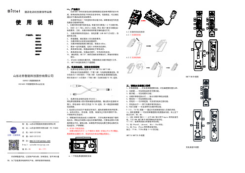
一、产品简介比特UM77系列浴室电话机是根据酒店实际使用要求设计而成,采用品质优异的电子材料及各项专利,性能稳定。
可以满足酒店对于酒店话机的实际需求。
本说明书包含7个机型的所有功能介绍,请根据各型号机型选看各功能使用说明。
1、无绳手柄可拨打接听电话,每部主机可配备1-4个无绳手柄。
2、支持1.8/1.9GHz、DECT6.0标准,符合WDCT(数字无绳电话)标准要求;主机、无绳手柄间采用数字编码通讯方式。
3、无绳手柄具有充电指示、低电告警(LOW BATT灯长亮)、快速充电功能。
4、带速拨键,满足客房人性化服务需求;5、无绳手柄可以实现五级音量调节。
6、无绳手柄具备线路闪断功能,常规为600ms。
7、最后一组号码重拨,挂机5分钟后自动消失。
8、具有保持功能,使通话线路处于等待状态。
9、具有闭音功能,在通话过程中,可关闭本机发送。
10、兼容高压、西门子、朗讯交换机信息留言灯,具备信息留言提示。
11、BT6550为单线无绳主机,可配接相应无绳手柄进行工作。
12、UM7715M座机具有三个速拨键。
二、电话机组装、拆卸及安装说明1、电源和电话线的连接(UM7715/UM7725/UM7715M):将电话分叉线电源插孔(下图1脚)与电源适配器连接,将分叉线RJ11四芯插头(下图2脚)与房间电话进线插座连接,将分叉线RJ11六芯插头(下图3脚)与话机背面TO TEL连接。
快思聪产品品技术参数描述大全

快思聪产品技术参数描述触摸屏系列 (3)TPS-4L (3)TPS-6L (4)TPSI-6X (4)CT-1000的技术参数: (4)STI-1550C单向无线触摸屏: (4)CT-1550C有线触摸屏: (5)STI-1700C单向无线触摸屏: (5)STXI-1700CXP双向无线触摸屏: (5)STXI-1700CXP双向无线触摸屏: (5)TPS-1700C触摸屏: (6)TPS-2000L: (6)TPS-3000L: (6)TPMC-8L的技术参数: (7)TPS-3000: (7)TPS-4000的技术参数: (7)TPS-4000L的技术参数: (8)MiniTouch:MT-1000C (8)MiniTouch:ML-500无线紧凑式射频LCD远程遥控器 (8)MiniTouch:ML-600无线紧凑式射频LCD远程遥控器 (9)MLX-2:MiniLCD2路RF掌上遥控 (9)WPR-48 具有防水性能的遥控器 (9)TPS-12 (9)TPS-15 (10)TPS-17 (10)TPMC-CH-IMC 界面模块 (11)TPS-12G-QM (11)TPS-15-G-QM (11)TPMC-4XG Isys i/O™ WiFi 触摸屏: (12)TPMC-8X Isys i/O™ WiFi 触摸屏 (12)TPMC-8X-DS技术参数: (13)TPMC-15-QM Isys i/O™ 15” 触摸屏媒体中心 (13)TPMC-17-QM Isys i/O™ 17”触摸屏媒体中心 (15)控制主机系列 (16)MC2E的技术参数: (17)MC2W的技术参数: (17)CP2的技术参数: (17)CP2E的技术参数: (17)A V2的技术参数: (18)PRO2的技术参数: (18)MP2的技术参数: (18)MP2E的技术参数: (19)C2N-MMS的技术参数: (19)CNXRMC: (19)CNXRMCLV: (19)C2N-DVP4DI的技术参数: (20)DVPHD-PRO的技术参数: (20)MPS-100的技术参数: (21)MPS-300技术参数: (23)PAC2的技术参数: (24)PAC2M - Pro Mini 控制主机技术参数 (24)AADSI的技术参数: (25)AESI的技术参数: (25)AAE音频扩展器技术参数: (25)音频(AAS) 技术参数: (25)TPS-ENET的技术参数: (26)TPS-VID-1的技术参数: (26)TPS-VID-2: (26)TPS-XVGA的技术参数: (26)CNXRY-16的技术参数: (26)C2IR-8的技术参数: (27)C2COM-2的技术参数: (27)C2COM-3的技术参数: (27)C2ENET-1的技术参数: (27)C2ENET-2的技术参数: (27)C2VEQ-4 (27)常用扩展模块 (28)TPS-XTX-RF的技术参数: (28)CEN-TIA电话接口模块技术参数: (28)C2N-VEQ-4 (28)STI-COM的技术参数: (29)CNECI-4A的技术参数: (29)CLI-220N-4的技术参数: (29)CHAO-12模拟量控制模块 (29)SP-4的技术参数: (29)C2N-CAMIDSPT数字伺服式摄像机电动云台 (30)C2N-CAMIDJ操纵杆控制器 (31)CNRFGW A无线接收器 (31)CNRFGW-418无线接收器 (31)STRFGW A双向接收器 (32)TPS-RFGWXI (32)CEN-RFGW-ZB:ZigBee网关 (32)CENI-HPRFGW:高性能电源RF网关 (32)CLSI-C6A的技术参数: (33)C2N-SSC-2 (33)C2N-SDC-DC (33)CNX-B2...B12: .. (33)C2N-CB的技术参数: (34)APAD的技术参数: (34)CEN-IDOC Apple iPod®界面技术参数 (34)MediaManager (34)QM-RMC (35)QM-WMC: 墙面媒体终端 (35)QM-WMIC:墙面媒体终端 (36)QM-RMCRX: 主处理器 (36)QM-FTCC: 弹出式计算机界面 (36)QM-FTSC: 上翻式存储中心 (37)QM-FTDC:上翻式数据中心 (37)QM-MD8x8: QM切换矩阵 (37)QM-MD7x2: 快思聪矩阵 (38)QM-MD5X1 (38)QM-TX (39)QM-RX: QuickMedia 接收器 (39)QM-FTCC-TPS (39)QM-RX1-3G: (40)QM-TX2-MC (40)QM-TX2-CC (40)QM-WMC-CC (41)QM-WCC-2 (41)QM-WCC-1 (41)网络解决方案 (41)CEN-W AP-ABG-1G:802.11a/b/g无线接入点 (42)CEN-SW-POE-5: 5埠PoE切换器 (42)PW-4803RU:PoE电源供应器 (42)ADAD六路数字音频服务器 (42)快思聪优惠套装解决方案 (43)TPMC-10 Isys i/O 10” WiFi 平板式触摸屏 (44)QM-AMP3x80MM: 块思聪功放 (45)CNPI-48 48键控制面板接口 (46)IRP2 红外线发射器探头 (47)触摸屏系列TPS-4L● 3.6 英寸有源矩阵彩色触摸屏●32 位Coldfire® 处理器●320x240 象素●8 MB 闪存,16M DRAM●16 位Isys™ 图像引擎●10个白色背光按键●可播放W A V音频文件●紧凑的、流行的嵌墙式触摸屏●可以通过以太网和Cresnet与主机通讯TPS-6L●紧凑的、流行的嵌墙式触摸屏●可以通过以太网和Cresnet与主机通讯●12个白色背光按键,并可刻字● 5.7 英寸有源矩阵彩色触摸屏●640x480 象素●16 位Isys™ 图像引擎●可播放W A V音频文件●支持PNG 和半透明化●支持动态图像,cover art, Adagio AS, Request, Windows Media Center.●内置麦克风●可伸缩视频窗口,支持视频显示●可选颜色杏仁、黑色、白色TPSI-6X●用于掌上和桌面式的轻便型轮廓设计● 5.7寸有源矩阵彩色触摸屏显示●16位isys图形●640*480分辨率●高速2.4GHz RF 无线技术●内置单向IR无线功能●有线以太网以及快思聪Home CAT5视频连接CT-1000的技术参数:● 3.8”墙装式彩色触摸屏;●256色;●10个常用指令快捷按钮;●可自由编程;●独家感光显示,可自行调节其亮度已适应周边环境;●可储存及重播W A V声音档案;STI-1550C单向无线触摸屏:● 5.7“彩色单向无线触摸屏;●320X240分辨率;●256色;●1M闪存;●可自由编程;●传输距离:300英尺(约100米);●包含可充电电池STI-BTPN、充电座STI-DSN;●无线接收器为CNRFGWA;CT-1550C有线触摸屏:●STI-1550C的有线版本;● 5.7“彩色触摸屏;●320X240分辨率;●256色;●1M闪存;●可自由编程;STI-1700C单向无线触摸屏:● 5.7“彩色单向无线触摸屏;●320X240分辨率;●64,000种色彩;●4M flash存储器,8M SDRAM内存●可自由编程;●10个可定义功能的快捷按键;●传输距离:300英尺(约100米);●包含可充电电池STI-BTPN、充电座STI-DSN;●无线接收器为CNRFGWA;STXI-1700CXP双向无线触摸屏:● 5.7“彩色双向无线触摸屏;●320X240分辨率;●64,000种色彩;●4M flash存储器,8M SDRAM内存●可自由编程;●10个可定义功能的快捷按键;●传输距离:300英尺(约100米);●包含可充电电池STI-BTPN、充电座STI-DSN;●无线接收器为STRFGWX;STXI-1700CXP双向无线触摸屏:● 5.7“彩色双向无线触摸屏;● 2.4G工作频率,WiFi 友好●320X240分辨率;●64,000种色彩;●4M flash存储器,8M SDRAM内存●可自由编程;●10个可定义功能的快捷按键;●传输距离:100-300英尺(约30-60米);●包含可充电电池STI-BTPN、充电座STI-DSN;●无线接收器为TPS-RFGWX;TPS-1700C触摸屏:● 5.7“彩色触摸屏;●320X240分辨率;●64,000种色彩;●4M flash存储器,8M SDRAM内存●可自由编程;●10个可定义功能的快捷按键;TPS-2000L:●5“彩色触摸屏;●320X234分辨率;●64,000种色彩;●32 MIPS Coldfire® 处理器●2M flash与8M DRAM内存;●可自由编程;●10个可定义功能的快捷按键;●平衡/非平衡视频输入●可存储播放W A V文件TPS-3000L:● 6.4“彩色挂墙式触摸屏;●640X480分辨率;●64,000种色彩;●可自由编程;●5个可定义功能的快捷按键;●8M flash,8M DRAM 存储器●1路视频输入显示;●内建麦克风;立体声扬声器●支持W A V文件格式;●内置控制RS-232 接口;TPMC-8L的技术参数:●8.4寸有源矩阵彩色触摸屏●800*600的分辨率●16位isys i/o图形●动态图形功能●DNav动态菜单对象●支持windows sideshow●内置网站浏览,流媒体,电子邮件,VOIP和远程计算机控制功能●多格式流动视频和音频●平衡音频输出●生物指纹扫描仪●16个可选按钮●背光灯雕刻可选●自动调光感应●WA V文件音频反馈功能●以太网通信●连接usb键盘和鼠标●墙面,讲桌和白色可选●有杏色,黑色和白色可选TPS-3000:● 6.4“彩色触摸屏;●640X480分辨率;●64,000种色彩;●可自由编程;●8M flash,8M DRAM 存储器●1路视频输入显示;●内建麦克风;立体声扬声器●支持W A V文件格式;●内置控制RS-232 接口;TPS-4000的技术参数:●10.4” 有源矩阵显示●16-Bit 彩色LCD●640x480 分辨率●Isys® 图形处理器: Synapse Rendering, etc.●8M flash,8M DRAM 存储器●可用于斜坡式讲台●一路视频输入,自动探测复合视频/S-Video格式●可调整的视频窗口或满屏显示●内嵌麦克风/扬声器(半双工,可用于对讲)●RS-232 端口,用来直接连接PCTPS-4000L的技术参数:●嵌墙式安装版本●10.4” 有源矩阵显示●16-Bit 彩色LCD●640x480 分辨率●Isys® 图形处理器: Synapse Rendering, etc.●8M flash,8M DRAM 存储器●一路视频输入,自动探测复合视频/S-Video格式●可调整的视频窗口或满屏显示●内嵌麦克风/扬声器(半双工,可用于对讲)●5个快捷按键,可编程MiniTouch:MT-1000C● 3.8”无线彩色触摸屏;●13个快捷按钮;可自由编程;●240X320分辨率;●16K色彩,高对比,可以显示3D效果●传输距离:100英尺(约30米);●无线接收器为CNRFGWA-418;●使用锂电池●配有充电底座MiniTouch:ML-500无线紧凑式射频LCD远程遥控器● 1.4“ x 2.1” LCD 显示器●27 个可编程按钮●导航轮式设计实现上、下、左、右,以及确认功能。
Kicker 43CWRT671 临时参数说明文件说明书
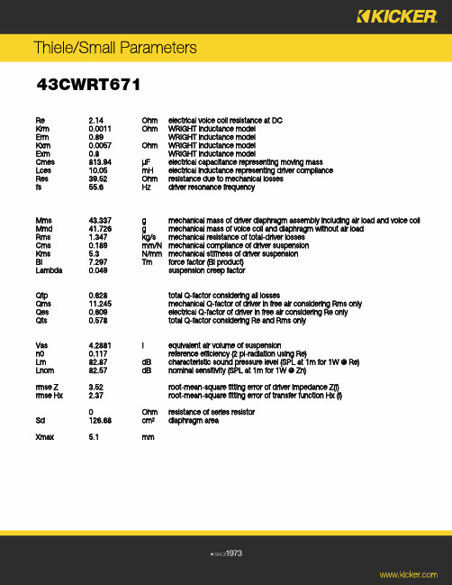
T h i e l e/S m a l l P a r a m e t e r s43CWRT671Re 2.14 Ohm electrical voice coil resistance at DCKrm 0.0011 Ohm WRIGHT inductance modelErm 0.89 WRIGHT inductance modelKxm 0.0057 Ohm WRIGHT inductance modelExm 0.8 WRIGHT inductance modelCmes 813.94 µF electrical capacitance representing moving massLces 10.05 mH electrical inductance representing driver complianceRes 39.52 Ohm resistance due to mechanical lossesfs 55.6 Hz driver resonance frequencyMms 43.337 g mechanical mass of driver diaphragm assembly including air load and voice coil Mmd 41.726 g mechanical mass of voice coil and diaphragm without air loadRms 1.347 kg/s mechanical resistance of total-driver lossesCms 0.189 mm/N mechanical compliance of driver suspensionKms 5.3 N/mm mechanical stiffness of driver suspensionBl 7.297 Tm force factor (Bl product)Lambda 0.049 suspension creep factorQtp 0.628 total Q-factor considering all lossesQms 11.245 mechanical Q-factor of driver in free air considering Rms onlyQes 0.609 electrical Q-factor of driver in free air considering Re onlyQts 0.578 total Q-factor considering Re and Rms onlyVas 4.2881 I equivalent air volume of suspensionn0 0.117 reference efficiency (2 pi-radiation using Re)Lm 82.87 dB characteristic sound pressure level (SPL at 1m for 1W @ Re)Lnom 82.57 dB nominal sensitivity (SPL at 1m for 1W @ Zn)rmse Z 3.52 root-mean-square fitting error of driver impedance Z(f)rmse Hx 2.37 root-mean-square fitting error of transfer function Hx (f)0 Ohm resistance of series resistorSd 126.68 cm² diaphragm areaXmax 5.1 mmw w w.k i c k e r.c o m。
- 1、下载文档前请自行甄别文档内容的完整性,平台不提供额外的编辑、内容补充、找答案等附加服务。
- 2、"仅部分预览"的文档,不可在线预览部分如存在完整性等问题,可反馈申请退款(可完整预览的文档不适用该条件!)。
- 3、如文档侵犯您的权益,请联系客服反馈,我们会尽快为您处理(人工客服工作时间:9:00-18:30)。
NPN SURFACE MOUNT DARLINGTON TRANSISTORFeatures• 40V Darlington Transistor • Epitaxial Planar Die Construction • Ideal for Low Power Amplification and Switching • High Current Gain • Ultra-Small Surface Mount Package • Lead Free, RoHS Compliant (Note 1) • Halogen and Antimony Free "Green" Device (Note 2)Mechanical Data• Case: SOT-323 • Case Material: Molded Plastic, "Green" Molding Compound,Note 4. UL Flammability Classification Rating 94V-0 • Moisture Sensitivity: Level 1 per J-STD-020 • Terminals: Solderable per MIL-STD-202, Method 208 • Lead Free Plating (Matte Tin Finish annealed over Alloy 42leadframe). • Weight: 0.006 grams (approximate)Ordering Information (Note 3)Product Marking Reel size (inches) Tape width (mm) Quantity per reel MMST6427-7-F K1D 7 8 3,000Notes: 1. No purposefully added lead.2. Diodes Inc.`s “Green” Policy can be found on our website at 3. For Packaging Details, go to our website at .Marking InformationDate Code KeyYear 2010 2011 2012 2013 2014 2015 Code X Y Z A B CMonth Jan Feb Mar Apr MayJun Jul Aug Sep Oct Nov DecCode 1 2 3 4 5 6 7 8 9 O N DK1D= Product Type Marking Code YM = Date Code Marking Y = Year ex: X = 2010M = Month ex: 9 = September K1DY MTop View Device symbolPin-out Top viewMaximum Ratings@T A = 25°C unless otherwise specifiedCharacteristic Symbol Value Unit Collector-Base Voltage V CBO40 V Collector-Emitter Voltage V CEO40 V Emitter-Base Voltage V EBO12 V Collector Current - Continuous (Note 4) I C500 mA Power Dissipation (Note 4) P d200 mW Thermal Resistance, Junction to Ambient (Note 4) RθJA625 °C/W Operating and Storage Temperature Range T j, T STG-55 to +150 °CElectrical Characteristics@T A = 25°C unless otherwise specifiedCharacteristic Symbol Min Max Unit Test Condition OFF CHARACTERISTICS (Note 5)Collector-Base Breakdown Voltage BV CBO40 ⎯V I C = 100μA, I E = 0 Collector-Emitter Breakdown Voltage BV CEO40 ⎯V I C = 10mA, I B = 0Emitter-Base Breakdown Voltage BV EBO12 ⎯V I E = 10μA, I C = 0Collector Cutoff Current I CBO⎯50 nA V CB = 30V, I E = 0 Collector Cutoff Current I CEO⎯ 1.0 μA V CE = 25V, I B = 0Emitter Cutoff Current I EBO⎯50 nA V EB = 10V, I C = 0ON CHARACTERISTICS (Note 5)DC Current Gain h FE 10,00020,00014,000100,000200,000140,000⎯I C = 10mA, V CE = 5.0VI C = 100mA, V CE = 5.0VI C = 500mA, V CE = 5.0VCollector-Emitter Saturation Voltage V CE(sat)⎯1.21.5VI C = 50mA, I B = 0.5mAI C = 500mA, I B = 0.5mABase-Emitter Saturation Voltage V BE(sat)⎯ 2.0 V I C = 500mA, I B = 0.5mABase-Emitter On Voltage V BE(on)⎯ 1.75 V I C = 50mA, V CE =5.0V SMALL SIGNAL CHARACTERISTICSOutput Capacitance C obo8.0 Typical pF V CB = 10V, f = 1.0MHz, I E = 0 Input Capacitance C ibo15 Typical pF V EB = 0.5V, f = 1.0MHz, I C = 0Notes: 4. Device mounted on 25mm x 22 mm x 1.6mm FR4 PCB, 1oz copper, singled sided5. Short duration pulse test used to minimize self-heating effect.1100V , C O L L E C T O R T O E M I T T E R S A T U R A T I O N V O L T A G E (V )C E (S A T )I , COLLECTOR CURRENT (mA)Fig. 2, Collector Emitter Saturation Voltage vs. Collector Current C 0.450.400.500.550.600.650.700.750.800.850.900.951.101.051.001001,000100,0001,000,00010,0001101,000100h , D C C U R R E N T G A I NF E I , COLLECTOR CURRENT (mA)Fig. 3, DC Current Gain vs. Collector CurrentCV , B A S E E M I T T E R V O L T A G E (V )B E (O N )I , COLLECTOR CURRENT (mA)Fig. 4, Base Emitter Voltage vs. Collector Current C 0.30.20.40.50.60.70.80.91.01.11.21.31.61.51.41101,000100110100f , G A I N B A N D W I D T H P R O D U C T (M H z )T I , COLLECTOR CURRENT (mA)Fig. 5, Gain Bandwidth Product vs. Collector CurrentCPackage Outline DimensionsSuggested Pad LayoutSOT323Dim Min Max Typ A 0.25 0.40 0.30 B 1.15 1.35 1.30 C 2.00 2.20 2.10 D - - 0.65 G 1.20 1.40 1.30 H 1.80 2.20 2.15 J 0.0 0.10 0.05 K 0.90 1.00 1.00 L 0.25 0.40 0.30 M 0.10 0.18 0.11α0° 8° - All Dimensions in mmDimensionsValue (in mm)Z2.8 X 0.7 Y 0.9C1.9E1.0XEYCZIMPORTANT NOTICEDIODES INCORPORATED MAKES NO WARRANTY OF ANY KIND, EXPRESS OR IMPLIED, WITH REGARDS TO THIS DOCUMENT, INCLUDING, BUT NOT LIMITED TO, THE IMPLIED WARRANTIES OF MERCHANTABILITY AND FITNESS FOR A PARTICULAR PURPOSE (AND THEIR EQUIVALENTS UNDER THE LAWS OF ANY JURISDICTION).Diodes Incorporated and its subsidiaries reserve the right to make modifications, enhancements, improvements, corrections or other changes without further notice to this document and any product described herein. Diodes Incorporated does not assume any liability arising out of the application or use of this document or any product described herein; neither does Diodes Incorporated convey any license under its patent or trademark rights, nor the rights of others. Any Customer or user of this document or products described herein in such applications shall assume all risks of such use and will agree to hold Diodes Incorporated and all the companies whose products are represented on Diodes Incorporated website, harmless against all damages.Diodes Incorporated does not warrant or accept any liability whatsoever in respect of any products purchased through unauthorized sales channel. Should Customers purchase or use Diodes Incorporated products for any unintended or unauthorized application, Customers shall indemnify and hold Diodes Incorporated and its representatives harmless against all claims, damages, expenses, and attorney fees arising out of, directly or indirectly, any claim of personal injury or death associated with such unintended or unauthorized application.Products described herein may be covered by one or more United States, international or foreign patents pending. Product names and markings noted herein may also be covered by one or more United States, international or foreign trademarks.LIFE SUPPORTDiodes Incorporated products are specifically not authorized for use as critical components in life support devices or systems without the express written approval of the Chief Executive Officer of Diodes Incorporated. As used herein:A. Life support devices or systems are devices or systems which:1. are intended to implant into the body, or2. support or sustain life and whose failure to perform when properly used in accordance with instructions for use provided in thelabeling can be reasonably expected to result in significant injury to the user.B. A critical component is any component in a life support device or system whose failure to perform can be reasonably expected to cause thefailure of the life support device or to affect its safety or effectiveness.Customers represent that they have all necessary expertise in the safety and regulatory ramifications of their life support devices or systems, and acknowledge and agree that they are solely responsible for all legal, regulatory and safety-related requirements concerning their products and any use of Diodes Incorporated products in such safety-critical, life support devices or systems, notwithstanding any devices- or systems-related information or support that may be provided by Diodes Incorporated. Further, Customers must fully indemnify Diodes Incorporated and its representatives against any damages arising out of the use of Diodes Incorporated products in such safety-critical, life support devices or systems.Copyright © 2011, Diodes Incorporated分销商库存信息:DIODESMMST6427-7MMST6427-7-F。
