Corrosion of TP347H FG stainless steel in a biomass fired PF utility boiler
TP347H奥氏体不锈钢锅炉管开裂原因分析

TP347H 奥氏体不锈钢锅炉管开裂原因分析郑坊平,张红军,高磊,刘森(西安热工研究院有限公司,陕西西安710032)摘要:通过宏观检查、化学成分分析、金相检验、硬度试验、断口分析及能谱分析等方法,对某电厂超临界锅炉末级再热器奥氏体不锈钢管的开裂原因进行了分析。
结果表明:TP347H异径管的横向开裂是在材质处于敏化状态、管子晶界受损的条件下,应力集中薄弱部位受轴向工作应力、弯矩和一定的焊接残余应力,发生了由外壁向内壁扩展的沿晶应力腐蚀开裂。
关键词:奥氏体不锈钢;材质敏化;沿晶应力腐蚀;横向开裂中图分类号:TG142.71;TG115.2 文献标识码:A 文章编号:1001-3814(2014)21-0225-04 Cracking Cause Analysis for TP347H Austenitic Stainless Steel Boiler TubeZHENG Fangping,ZHANG Hongjun,GAO Lei,L IU Shen(Thermal Power Research Institute, Xi'an 710032, China)Ab st r act:B y visual testing,chem ical com position analysis,m etallographic exam ination,hardness testing,fracture analysis and energy spectrum analysis,the cracking causes for austenitic stainless steel of finishing reheater in supercritical boiler were analyzed.The results show that the transverse crack of TP347H reducer is intergranular stress corrosion cracking, which is from outside wall into inside wall,when the m aterial is in the sensitized state and the tube grain boundary dam ages, and the stress concentration part has the axial working stress,bending m om ent and welding residual stress.Key w ords:austenitic s tainless s teel; m aterial s ensitization; i ntergranular s tress c orrosion; t ransverse c racking某电厂1台锅炉系SG-2141/25.4-M978型、一次中间再热、四角切圆燃烧的660MW超临界压力直流锅炉。
凝固冷却速率对2507超级双相不锈钢微观组织的演变及耐蚀性能的影响

Vol.54 N o.4 Apr. 2021凝固冷却速率对2507超级双相不锈钢微观组织的演变及耐蚀性能的影响沈楚,邹德宁,赵洁,陈阳(西安建筑科技大学冶金工程学院,陕西西安710055)[摘要]为探究凝固冷却速率对2507超级双相不锈钢微观组织与耐蚀性能的影响,采用光学显微镜(0M)和 扫描电子显微镜(S E M)研究了不同凝固冷却速率2507超级双相不锈钢的微观组织演变规律,并结合Image-P r o图像分析软件与铁素体分析仪,确定了各不同凝固冷速试样组织中的各相含量,得到了凝固冷却速率对c t相析出的 影响规律及(T相的析出机理。
再采用动电位极化法与交流阻抗谱法研究了各不同凝固冷却速率2507超级双相不 锈钢的耐蚀性能。
结果表明:试样组织中的(T析出相含量随着凝固冷却速率的降低而增加,试样的耐蚀性能随着 凝固冷却速度的降低而减弱。
[关键词]2507超级双相不锈钢;凝固冷却速率;<7析出相;微观组织;耐蚀性能[中图分类号]T G506.7+1 [文献标识码]A[文章编号]100卜1560(2021)04-0074-06Effect of Solidification Cooling Rate on the Microstructure Evolution andCorrosion Resistance of 2507 Super Duplex Stainless SteelS H F.N C h u,Z O U De-ning, Z H A O Jie, C H E N Y a n g(School of Metallurgy and Engineering, X i*a n University of Architecture and Technology, X i'a n 710055, China)Abstract:For exploring the influence of solidification cooling rate on the microstructure evolution and corrosion resistance of 2507 super duplex stainless steel, the law of the microstructure evolution of 2507super duplex stainless steel with different solidification cooling rates was investigated by optical microscope (O M)and scanning electron microscope (S E M). T h e contents of each phase in the samples with different solidification cooling rates were determined by Image-Pro image analysis software and ferrite analyzer, and the effect of solidification rate on the precipitation of a phase and the precipitation m e c h a n i s m of a phase were obtained. Furthermore, the corrosion resistance properties of 2507 super duplex stainless steel with different solidification and cooling rates were investigated by potentiodynamic polarization and electrochemical impedance spectroscopy. Results showed that the content of a phase in the samples structure increased with the decrease of solidification cooling rate, and the corrosion resistance of the samples weakened with the decrease of solidification ccxjling rate.Key words:2507 super duplex stainless steel;solidification cooling rate;a p h ase;microstructure;corrosion resistance〇前言2507超级双相不锈钢是超低碳并具有较高合金含 量的一种高性能不锈钢,它兼具有铁素体不锈钢和奥 氏体不锈钢的优点,而其中最为突出的是它具有比普 通双相不锈钢更优异的耐腐蚀性能。
常用国内外钢号对照表

SUS304
JISG4304/4305/4312 SUS310S、SUH310 JISG4304/4305/4312 SUS316 JISG4304/4305/4312 SUS316L
注:不锈钢类别中括号内中国牌号为老标准中牌号 Note: The Chinese material trademark inside ( ) are old standard trademark of stainless. SEW087 WTSt37-3 住友 Sumitomo CR1A400 新日铁 Nippon Steel S-Ten1 住友 Sumitomo CR1A490 新日铁 Nippon Steel S-Ten2 住友 Sumitomo CR1A490 新日铁 Nippon Steel S-Ten3 住友 Sumitomo CR2R-H JIS G3125 SPA-H
(X12CrNi2521) DIN17440 X5CrNi18 9 (1.4301) DIN17440 X2CrNi18 9 (1.4306) DIN17440 X2CrNiMo1810 (1.4401) DIN17440 X2CrNiMo1812 (1.4435)
不锈钢 Stainless steel
5
KBC-001
结构钢 Structural steel
分类 Classify
中国 CHINA (GB)
GB/T699 20
美国 AMERICA (ASME)
SA29 1020 SA29 1025 SA29 1035 SA29 1045 -SA29 B11 SA29 4130 SA29 4135 --------ASTM A276 420 ASTM A276 420S45 SA479 321H
新型奥氏体耐热钢HR3C的研究进展
·44·2010年第2期量分数为0.15%~0.35%的N,利用析出弥散分布、细小的NbCrN相和富Nb的碳、氮化物以及M:,C。
来进行强化,成功地开发了新型奥氏体耐热钢HR3C,其蠕变断裂强度明显提高到181MPa。
HR3C钢种的开发过程如图l所示。
图1HR3C钢的发展历程综合考虑,与其他耐热钢相比,HR3C具有优良的蠕变断裂强度和更优良的抗蒸汽和烟气的氧化性能,因此更适合用于超超临界机组中环境极为恶劣的锅炉过热器和再热器部件的末级管道中。
3.1基本组织如前文所述,HR3C是以奥氏体为基体,析出细小、弥散分布的NbCrN、MX和M:,C。
三种强化相,同时有可能析出Cr2N相、盯相和G相。
其固溶态的金相组织见图2。
图2HR3C钢固溶状态的金相照片尽管在ASME标准中规定了HR3C钢的合金元素及其成分范围,但实际上,在国外研发过程中对其成分范围有着更为严格的要求。
表2中给出了国外研发的HR3C钢管成分质量分数川。
表2国外研发的HR3C钢管成分质量分数%将表1和表2对比分析可知,国外研发过程中不仅对材料的主要合金元素有着严格的限制,同时对其他元素Si、Mn、P、S等也有严格的限制。
对C、P、S的限制主要是为了有利于材料的焊接;Si、Mn属于促进盯相形成元素,对它们进行适当的限制是为了抑制盯相的析出。
Nb处于中卜限(表1),与N、c、cr配合可起到较为明显的沉淀强化和时效强化效果。
而对于Ni和N元素,有试验证明,当Ni和N质量分数低于中下限时(表1),在长期时效过程中会析出盯相;而当Ni和N质量分数高于中卜限时(表1),除.r会析出富Nb的碳氮化物,还会析出Cr2N、1T相而降低材料的韧性。
N与c一样,同为问隙元素,增加钢中N质量分数,可改善材料的高温强度,并稳定奥氏体相,改善抗晶问腐蚀与点腐蚀性能。
文献[11]报道了对国外供货HR3C钢管成分进行鉴定,发现在材料中添加了Co、B、灿等元素,认为有些元素如B是特意添加在材料中的,可改善材料晶间腐蚀性能,提高热塑性,改善热加工性以及影响钢中晶界第二相的析出和分布状态,从而提高HR3C的高温强度。
IEC-61854架空线.隔离层的要求和检验

NORMEINTERNATIONALECEI IEC INTERNATIONALSTANDARD 61854Première éditionFirst edition1998-09Lignes aériennes –Exigences et essais applicables aux entretoisesOverhead lines –Requirements and tests for spacersCommission Electrotechnique InternationaleInternational Electrotechnical Commission Pour prix, voir catalogue en vigueurFor price, see current catalogue© IEC 1998 Droits de reproduction réservés Copyright - all rights reservedAucune partie de cette publication ne peut être reproduite niutilisée sous quelque forme que ce soit et par aucunprocédé, électronique ou mécanique, y compris la photo-copie et les microfilms, sans l'accord écrit de l'éditeur.No part of this publication may be reproduced or utilized in any form or by any means, electronic or mechanical,including photocopying and microfilm, without permission in writing from the publisher.International Electrotechnical Commission 3, rue de Varembé Geneva, SwitzerlandTelefax: +41 22 919 0300e-mail: inmail@iec.ch IEC web site http: //www.iec.chCODE PRIX PRICE CODE X– 2 –61854 © CEI:1998SOMMAIREPages AVANT-PROPOS (6)Articles1Domaine d'application (8)2Références normatives (8)3Définitions (12)4Exigences générales (12)4.1Conception (12)4.2Matériaux (14)4.2.1Généralités (14)4.2.2Matériaux non métalliques (14)4.3Masse, dimensions et tolérances (14)4.4Protection contre la corrosion (14)4.5Aspect et finition de fabrication (14)4.6Marquage (14)4.7Consignes d'installation (14)5Assurance de la qualité (16)6Classification des essais (16)6.1Essais de type (16)6.1.1Généralités (16)6.1.2Application (16)6.2Essais sur échantillon (16)6.2.1Généralités (16)6.2.2Application (16)6.2.3Echantillonnage et critères de réception (18)6.3Essais individuels de série (18)6.3.1Généralités (18)6.3.2Application et critères de réception (18)6.4Tableau des essais à effectuer (18)7Méthodes d'essai (22)7.1Contrôle visuel (22)7.2Vérification des dimensions, des matériaux et de la masse (22)7.3Essai de protection contre la corrosion (22)7.3.1Composants revêtus par galvanisation à chaud (autres queles fils d'acier galvanisés toronnés) (22)7.3.2Produits en fer protégés contre la corrosion par des méthodes autresque la galvanisation à chaud (24)7.3.3Fils d'acier galvanisé toronnés (24)7.3.4Corrosion causée par des composants non métalliques (24)7.4Essais non destructifs (24)61854 © IEC:1998– 3 –CONTENTSPage FOREWORD (7)Clause1Scope (9)2Normative references (9)3Definitions (13)4General requirements (13)4.1Design (13)4.2Materials (15)4.2.1General (15)4.2.2Non-metallic materials (15)4.3Mass, dimensions and tolerances (15)4.4Protection against corrosion (15)4.5Manufacturing appearance and finish (15)4.6Marking (15)4.7Installation instructions (15)5Quality assurance (17)6Classification of tests (17)6.1Type tests (17)6.1.1General (17)6.1.2Application (17)6.2Sample tests (17)6.2.1General (17)6.2.2Application (17)6.2.3Sampling and acceptance criteria (19)6.3Routine tests (19)6.3.1General (19)6.3.2Application and acceptance criteria (19)6.4Table of tests to be applied (19)7Test methods (23)7.1Visual examination (23)7.2Verification of dimensions, materials and mass (23)7.3Corrosion protection test (23)7.3.1Hot dip galvanized components (other than stranded galvanizedsteel wires) (23)7.3.2Ferrous components protected from corrosion by methods other thanhot dip galvanizing (25)7.3.3Stranded galvanized steel wires (25)7.3.4Corrosion caused by non-metallic components (25)7.4Non-destructive tests (25)– 4 –61854 © CEI:1998 Articles Pages7.5Essais mécaniques (26)7.5.1Essais de glissement des pinces (26)7.5.1.1Essai de glissement longitudinal (26)7.5.1.2Essai de glissement en torsion (28)7.5.2Essai de boulon fusible (28)7.5.3Essai de serrage des boulons de pince (30)7.5.4Essais de courant de court-circuit simulé et essais de compressionet de traction (30)7.5.4.1Essai de courant de court-circuit simulé (30)7.5.4.2Essai de compression et de traction (32)7.5.5Caractérisation des propriétés élastiques et d'amortissement (32)7.5.6Essais de flexibilité (38)7.5.7Essais de fatigue (38)7.5.7.1Généralités (38)7.5.7.2Oscillation de sous-portée (40)7.5.7.3Vibrations éoliennes (40)7.6Essais de caractérisation des élastomères (42)7.6.1Généralités (42)7.6.2Essais (42)7.6.3Essai de résistance à l'ozone (46)7.7Essais électriques (46)7.7.1Essais d'effet couronne et de tension de perturbations radioélectriques..467.7.2Essai de résistance électrique (46)7.8Vérification du comportement vibratoire du système faisceau/entretoise (48)Annexe A (normative) Informations techniques minimales à convenirentre acheteur et fournisseur (64)Annexe B (informative) Forces de compression dans l'essai de courantde court-circuit simulé (66)Annexe C (informative) Caractérisation des propriétés élastiques et d'amortissementMéthode de détermination de la rigidité et de l'amortissement (70)Annexe D (informative) Contrôle du comportement vibratoire du systèmefaisceau/entretoise (74)Bibliographie (80)Figures (50)Tableau 1 – Essais sur les entretoises (20)Tableau 2 – Essais sur les élastomères (44)61854 © IEC:1998– 5 –Clause Page7.5Mechanical tests (27)7.5.1Clamp slip tests (27)7.5.1.1Longitudinal slip test (27)7.5.1.2Torsional slip test (29)7.5.2Breakaway bolt test (29)7.5.3Clamp bolt tightening test (31)7.5.4Simulated short-circuit current test and compression and tension tests (31)7.5.4.1Simulated short-circuit current test (31)7.5.4.2Compression and tension test (33)7.5.5Characterisation of the elastic and damping properties (33)7.5.6Flexibility tests (39)7.5.7Fatigue tests (39)7.5.7.1General (39)7.5.7.2Subspan oscillation (41)7.5.7.3Aeolian vibration (41)7.6Tests to characterise elastomers (43)7.6.1General (43)7.6.2Tests (43)7.6.3Ozone resistance test (47)7.7Electrical tests (47)7.7.1Corona and radio interference voltage (RIV) tests (47)7.7.2Electrical resistance test (47)7.8Verification of vibration behaviour of the bundle-spacer system (49)Annex A (normative) Minimum technical details to be agreed betweenpurchaser and supplier (65)Annex B (informative) Compressive forces in the simulated short-circuit current test (67)Annex C (informative) Characterisation of the elastic and damping propertiesStiffness-Damping Method (71)Annex D (informative) Verification of vibration behaviour of the bundle/spacer system (75)Bibliography (81)Figures (51)Table 1 – Tests on spacers (21)Table 2 – Tests on elastomers (45)– 6 –61854 © CEI:1998 COMMISSION ÉLECTROTECHNIQUE INTERNATIONALE––––––––––LIGNES AÉRIENNES –EXIGENCES ET ESSAIS APPLICABLES AUX ENTRETOISESAVANT-PROPOS1)La CEI (Commission Electrotechnique Internationale) est une organisation mondiale de normalisation composéede l'ensemble des comités électrotechniques nationaux (Comités nationaux de la CEI). La CEI a pour objet de favoriser la coopération internationale pour toutes les questions de normalisation dans les domaines de l'électricité et de l'électronique. A cet effet, la CEI, entre autres activités, publie des Normes internationales.Leur élaboration est confiée à des comités d'études, aux travaux desquels tout Comité national intéressé par le sujet traité peut participer. Les organisations internationales, gouvernementales et non gouvernementales, en liaison avec la CEI, participent également aux travaux. La CEI collabore étroitement avec l'Organisation Internationale de Normalisation (ISO), selon des conditions fixées par accord entre les deux organisations.2)Les décisions ou accords officiels de la CEI concernant les questions techniques représentent, dans la mesuredu possible un accord international sur les sujets étudiés, étant donné que les Comités nationaux intéressés sont représentés dans chaque comité d’études.3)Les documents produits se présentent sous la forme de recommandations internationales. Ils sont publiéscomme normes, rapports techniques ou guides et agréés comme tels par les Comités nationaux.4)Dans le but d'encourager l'unification internationale, les Comités nationaux de la CEI s'engagent à appliquer defaçon transparente, dans toute la mesure possible, les Normes internationales de la CEI dans leurs normes nationales et régionales. Toute divergence entre la norme de la CEI et la norme nationale ou régionale correspondante doit être indiquée en termes clairs dans cette dernière.5)La CEI n’a fixé aucune procédure concernant le marquage comme indication d’approbation et sa responsabilitén’est pas engagée quand un matériel est déclaré conforme à l’une de ses normes.6) L’attention est attirée sur le fait que certains des éléments de la présente Norme internationale peuvent fairel’objet de droits de propriété intellectuelle ou de droits analogues. La CEI ne saurait être tenue pour responsable de ne pas avoir identifié de tels droits de propriété et de ne pas avoir signalé leur existence.La Norme internationale CEI 61854 a été établie par le comité d'études 11 de la CEI: Lignes aériennes.Le texte de cette norme est issu des documents suivants:FDIS Rapport de vote11/141/FDIS11/143/RVDLe rapport de vote indiqué dans le tableau ci-dessus donne toute information sur le vote ayant abouti à l'approbation de cette norme.L’annexe A fait partie intégrante de cette norme.Les annexes B, C et D sont données uniquement à titre d’information.61854 © IEC:1998– 7 –INTERNATIONAL ELECTROTECHNICAL COMMISSION––––––––––OVERHEAD LINES –REQUIREMENTS AND TESTS FOR SPACERSFOREWORD1)The IEC (International Electrotechnical Commission) is a worldwide organization for standardization comprisingall national electrotechnical committees (IEC National Committees). The object of the IEC is to promote international co-operation on all questions concerning standardization in the electrical and electronic fields. To this end and in addition to other activities, the IEC publishes International Standards. Their preparation is entrusted to technical committees; any IEC National Committee interested in the subject dealt with may participate in this preparatory work. International, governmental and non-governmental organizations liaising with the IEC also participate in this preparation. The IEC collaborates closely with the International Organization for Standardization (ISO) in accordance with conditions determined by agreement between the two organizations.2)The formal decisions or agreements of the IEC on technical matters express, as nearly as possible, aninternational consensus of opinion on the relevant subjects since each technical committee has representation from all interested National Committees.3)The documents produced have the form of recommendations for international use and are published in the formof standards, technical reports or guides and they are accepted by the National Committees in that sense.4)In order to promote international unification, IEC National Committees undertake to apply IEC InternationalStandards transparently to the maximum extent possible in their national and regional standards. Any divergence between the IEC Standard and the corresponding national or regional standard shall be clearly indicated in the latter.5)The IEC provides no marking procedure to indicate its approval and cannot be rendered responsible for anyequipment declared to be in conformity with one of its standards.6) Attention is drawn to the possibility that some of the elements of this International Standard may be the subjectof patent rights. The IEC shall not be held responsible for identifying any or all such patent rights. International Standard IEC 61854 has been prepared by IEC technical committee 11: Overhead lines.The text of this standard is based on the following documents:FDIS Report on voting11/141/FDIS11/143/RVDFull information on the voting for the approval of this standard can be found in the report on voting indicated in the above table.Annex A forms an integral part of this standard.Annexes B, C and D are for information only.– 8 –61854 © CEI:1998LIGNES AÉRIENNES –EXIGENCES ET ESSAIS APPLICABLES AUX ENTRETOISES1 Domaine d'applicationLa présente Norme internationale s'applique aux entretoises destinées aux faisceaux de conducteurs de lignes aériennes. Elle recouvre les entretoises rigides, les entretoises flexibles et les entretoises amortissantes.Elle ne s'applique pas aux espaceurs, aux écarteurs à anneaux et aux entretoises de mise à la terre.NOTE – La présente norme est applicable aux pratiques de conception de lignes et aux entretoises les plus couramment utilisées au moment de sa rédaction. Il peut exister d'autres entretoises auxquelles les essais spécifiques décrits dans la présente norme ne s'appliquent pas.Dans de nombreux cas, les procédures d'essai et les valeurs d'essai sont convenues entre l'acheteur et le fournisseur et sont énoncées dans le contrat d'approvisionnement. L'acheteur est le mieux à même d'évaluer les conditions de service prévues, qu'il convient d'utiliser comme base à la définition de la sévérité des essais.La liste des informations techniques minimales à convenir entre acheteur et fournisseur est fournie en annexe A.2 Références normativesLes documents normatifs suivants contiennent des dispositions qui, par suite de la référence qui y est faite, constituent des dispositions valables pour la présente Norme internationale. Au moment de la publication, les éditions indiquées étaient en vigueur. Tout document normatif est sujet à révision et les parties prenantes aux accords fondés sur la présente Norme internationale sont invitées à rechercher la possibilité d'appliquer les éditions les plus récentes des documents normatifs indiqués ci-après. Les membres de la CEI et de l'ISO possèdent le registre des Normes internationales en vigueur.CEI 60050(466):1990, Vocabulaire Electrotechnique International (VEI) – Chapitre 466: Lignes aériennesCEI 61284:1997, Lignes aériennes – Exigences et essais pour le matériel d'équipementCEI 60888:1987, Fils en acier zingué pour conducteurs câblésISO 34-1:1994, Caoutchouc vulcanisé ou thermoplastique – Détermination de la résistance au déchirement – Partie 1: Eprouvettes pantalon, angulaire et croissantISO 34-2:1996, Caoutchouc vulcanisé ou thermoplastique – Détermination de la résistance au déchirement – Partie 2: Petites éprouvettes (éprouvettes de Delft)ISO 37:1994, Caoutchouc vulcanisé ou thermoplastique – Détermination des caractéristiques de contrainte-déformation en traction61854 © IEC:1998– 9 –OVERHEAD LINES –REQUIREMENTS AND TESTS FOR SPACERS1 ScopeThis International Standard applies to spacers for conductor bundles of overhead lines. It covers rigid spacers, flexible spacers and spacer dampers.It does not apply to interphase spacers, hoop spacers and bonding spacers.NOTE – This standard is written to cover the line design practices and spacers most commonly used at the time of writing. There may be other spacers available for which the specific tests reported in this standard may not be applicable.In many cases, test procedures and test values are left to agreement between purchaser and supplier and are stated in the procurement contract. The purchaser is best able to evaluate the intended service conditions, which should be the basis for establishing the test severity.In annex A, the minimum technical details to be agreed between purchaser and supplier are listed.2 Normative referencesThe following normative documents contain provisions which, through reference in this text, constitute provisions of this International Standard. At the time of publication of this standard, the editions indicated were valid. All normative documents are subject to revision, and parties to agreements based on this International Standard are encouraged to investigate the possibility of applying the most recent editions of the normative documents indicated below. Members of IEC and ISO maintain registers of currently valid International Standards.IEC 60050(466):1990, International Electrotechnical vocabulary (IEV) – Chapter 466: Overhead linesIEC 61284:1997, Overhead lines – Requirements and tests for fittingsIEC 60888:1987, Zinc-coated steel wires for stranded conductorsISO 34-1:1994, Rubber, vulcanized or thermoplastic – Determination of tear strength – Part 1: Trouser, angle and crescent test piecesISO 34-2:1996, Rubber, vulcanized or thermoplastic – Determination of tear strength – Part 2: Small (Delft) test piecesISO 37:1994, Rubber, vulcanized or thermoplastic – Determination of tensile stress-strain properties– 10 –61854 © CEI:1998 ISO 188:1982, Caoutchouc vulcanisé – Essais de résistance au vieillissement accéléré ou à la chaleurISO 812:1991, Caoutchouc vulcanisé – Détermination de la fragilité à basse températureISO 815:1991, Caoutchouc vulcanisé ou thermoplastique – Détermination de la déformation rémanente après compression aux températures ambiantes, élevées ou bassesISO 868:1985, Plastiques et ébonite – Détermination de la dureté par pénétration au moyen d'un duromètre (dureté Shore)ISO 1183:1987, Plastiques – Méthodes pour déterminer la masse volumique et la densitérelative des plastiques non alvéolairesISO 1431-1:1989, Caoutchouc vulcanisé ou thermoplastique – Résistance au craquelage par l'ozone – Partie 1: Essai sous allongement statiqueISO 1461,— Revêtements de galvanisation à chaud sur produits finis ferreux – Spécifications1) ISO 1817:1985, Caoutchouc vulcanisé – Détermination de l'action des liquidesISO 2781:1988, Caoutchouc vulcanisé – Détermination de la masse volumiqueISO 2859-1:1989, Règles d'échantillonnage pour les contrôles par attributs – Partie 1: Plans d'échantillonnage pour les contrôles lot par lot, indexés d'après le niveau de qualité acceptable (NQA)ISO 2859-2:1985, Règles d'échantillonnage pour les contrôles par attributs – Partie 2: Plans d'échantillonnage pour les contrôles de lots isolés, indexés d'après la qualité limite (QL)ISO 2921:1982, Caoutchouc vulcanisé – Détermination des caractéristiques à basse température – Méthode température-retrait (essai TR)ISO 3417:1991, Caoutchouc – Détermination des caractéristiques de vulcanisation à l'aide du rhéomètre à disque oscillantISO 3951:1989, Règles et tables d'échantillonnage pour les contrôles par mesures des pourcentages de non conformesISO 4649:1985, Caoutchouc – Détermination de la résistance à l'abrasion à l'aide d'un dispositif à tambour tournantISO 4662:1986, Caoutchouc – Détermination de la résilience de rebondissement des vulcanisats––––––––––1) A publierThis is a preview - click here to buy the full publication61854 © IEC:1998– 11 –ISO 188:1982, Rubber, vulcanized – Accelerated ageing or heat-resistance testsISO 812:1991, Rubber, vulcanized – Determination of low temperature brittlenessISO 815:1991, Rubber, vulcanized or thermoplastic – Determination of compression set at ambient, elevated or low temperaturesISO 868:1985, Plastics and ebonite – Determination of indentation hardness by means of a durometer (Shore hardness)ISO 1183:1987, Plastics – Methods for determining the density and relative density of non-cellular plasticsISO 1431-1:1989, Rubber, vulcanized or thermoplastic – Resistance to ozone cracking –Part 1: static strain testISO 1461, — Hot dip galvanized coatings on fabricated ferrous products – Specifications1)ISO 1817:1985, Rubber, vulcanized – Determination of the effect of liquidsISO 2781:1988, Rubber, vulcanized – Determination of densityISO 2859-1:1989, Sampling procedures for inspection by attributes – Part 1: Sampling plans indexed by acceptable quality level (AQL) for lot-by-lot inspectionISO 2859-2:1985, Sampling procedures for inspection by attributes – Part 2: Sampling plans indexed by limiting quality level (LQ) for isolated lot inspectionISO 2921:1982, Rubber, vulcanized – Determination of low temperature characteristics –Temperature-retraction procedure (TR test)ISO 3417:1991, Rubber – Measurement of vulcanization characteristics with the oscillating disc curemeterISO 3951:1989, Sampling procedures and charts for inspection by variables for percent nonconformingISO 4649:1985, Rubber – Determination of abrasion resistance using a rotating cylindrical drum deviceISO 4662:1986, Rubber – Determination of rebound resilience of vulcanizates–––––––––1) To be published.。
常用国内外钢号对照表
SA240 309S
(X12CrNi2212)
JISG4304/4305/4312 SUS309S、SUH309
不锈钢
GB24511 06Cr25Ni20 (0Cr25Ni20)
SA240 310
(X12CrNi2521)
JISG4304/4305/4312 SUS310S、SUH310
Stainless steel
---
---
-------
---
日本 JAPAN
(JIS)
住友 Sumitomo CR2-400
JIS G3114 SMA400P 住友 Sumitomo CR2M-400 JIS G3114 SMA400W 住友 Sumitomo CR2-490
JIS G3114 SMA490P 住友 Sumitomo CR2M-490 JIS G3114 SMA490W 住友 Sumitomo CR2-520 住友 Sumitomo CR2-590
武汉凯比思电力设备有限公司标准
WUHAN KEMPINSH POWER EQUIPMENT CO., LTD STANDARD
KBC-001
常用国内外钢铁牌号对照表
The common material trademark parallel table of
CHINA & AMERICA
KBS 技术研发部 KBS R&D Dept.
美国 AMERICA
(ASME)
SA210 Gr.A-1 SA210 Gr.A-1 SA106 Gr.B SA106-C SA210-C SA209-T1 SA335-P1 SA213-T2 SA335-P2 SA213-T12 SA335-P12 SA213-T22 SA335-P22
304不锈钢板的钝化处理及耐蚀性
2020年3月电镀与环保第40卷第2期(总第232期)*37-304不锈钢板的钝化处理及耐蚀性Passivati o n Treatment and Corrosi o n Resistance o f304Stainless Steel Plate仝源(南京科技职业学院,江苏南京210048)TONG Yuan(Nanjing Polytechnic Institute,Nanjing210048,China)摘要:使用硝酸和重珞酸钾的混合液对304不锈钢板进行了钝化处理。
研究发现:不锈钢表面钝化过程伴随着钝化膜的生成和溶解。
与304不锈钢板相比,钝化膜中铬和氧的质量分数提高。
钝化膜主要由金属氧化物和金属氢氧化物构成。
经过钝化处理后,304不锈钢板的自腐蚀电位正移,自腐蚀电流密度降低,膜电阻升高,耐蚀性增强。
关键词:304不锈钢板;钝化膜;耐蚀性Abstract:304stainless steel plate was passivated in a mixture of nitric acid and potassium dichromate.It was found that the passivation of stainless steel was accompanied by the formation and dissolution of passivation pared with304stainless steel plate,the mass fraction of chromium and oxygen in the passivation film were increased obviously.The passivation film was composed of metal oxide and metal hydroxide.After passivation treatment,the self-corrosion potential of304stainless steel moved towards the positive direction,the self-corrosion current density was decreased and the film resistance was increased,thus resulting in the improvement of corrosionresistance.Key words:304stainless steel plate;passivation film;corrosion resistance中图分类号:TG174文献标志码:A文章编号:10004742(2020)020037030前言不锈钢是一种具有综合性能的合金钢,已广泛应用于汽车、化工、航空航天等领域X。
f347h化学成分

f347h化学成分Chemical composition of f347h refers to the specific elements and compounds that make up this particular type of steel. F347h is a high-grade stainless steel alloy that is commonly used in various industries due to its exceptional properties. Understanding its chemical composition is essential for engineers, manufacturers, and researchers to determine its suitability for specific applications and to ensure its quality and performance.F347h primarily consists of iron (Fe), which is the base element of most steel alloys. Iron provides the structural strength and durability to the material. Additionally, it contains chromium (Cr), which is a crucial element in stainless steel alloys. Chromium enhances the corrosion resistance of f347h, making it highly resistant to rust and oxidation. The chromium content in f347h is typically around 17-20%.Another significant element in the chemical compositionof f347h is nickel (Ni). Nickel improves the material's resistance to high temperatures and corrosion, particularly in acidic environments. The nickel content in f347h is usually around 9-13%. Furthermore, f347h contains small amounts of other elements such as carbon (C), manganese (Mn), silicon (Si), and phosphorus (P), which contribute to its overall properties and performance.Carbon is an essential element in steel alloys as it provides strength and hardness. The carbon content in f347h is typically limited to a maximum of 0.08%, ensuring that the material remains highly weldable and resistant to sensitization. Manganese acts as a deoxidizer and improves the material's mechanical properties, while silicon enhances its resistance to oxidation and scaling at high temperatures.Phosphorus is a trace element in f347h, and its presence is usually limited to very low levels to prevent brittleness and improve the material's toughness. Additionally, f347h may contain small amounts of sulfur (S) and nitrogen (N), which are controlled to ensure thematerial's quality and performance.From a practical perspective, the chemical composition of f347h makes it suitable for various applications. Its high chromium and nickel content provide excellent resistance to corrosion and oxidation, making it ideal for use in environments with high temperatures and acidic conditions. Additionally, its low carbon content ensures good weldability and prevents sensitization, which can lead to intergranular corrosion.Moreover, the presence of other elements in f347h, such as manganese and silicon, further enhances its mechanical properties, making it a reliable choice for structural components and pressure vessels. The controlled amounts of phosphorus, sulfur, and nitrogen ensure the material's quality and prevent any adverse effects on its performance.In conclusion, the chemical composition of f347h stainless steel alloy consists primarily of iron, chromium, and nickel, along with small amounts of carbon, manganese, silicon, phosphorus, sulfur, and nitrogen. These elementswork together to provide exceptional corrosion resistance, high-temperature strength, and weldability. The precise control of these elements ensures the material's quality and performance, making f347h a versatile and reliable choice for various industrial applications.。
TP347HFG冷弯后固溶问题探讨
的应 用 越 来 越 多 ,众 多 6 0 0 WM 机 组 的高 温 受 热 面 的 改 造 选 用 该 种 材 料 。但 在 炉 管 冷 弯 后 ,
1 工 艺 及 原 材 料 的选 择
国 内大 型 机 组 近 几 年 氧 化 皮 问题 引起 的 锅 炉爆 管 事 故频 繁发 生 ,为解 决 这 一 问题 需 要 提 高锅 炉 用钢 的抗 高温 蒸 汽腐 蚀 能力 。研 究表 明 , 为 提 高 抗 高 温蒸 汽腐 蚀 能力 .需 要 细 化 钢 材 的
管子 的弯头 处易 产生应 力腐 蚀 裂纹 。为 避免 因冷
加工成型而导致晶间腐蚀和应力腐蚀 断裂 ,AS ME 标 准建 议 ,当设 计 金 属 温 度在 5 4 0~6 7 5℃ ,变
形量超过 1 5 % 时需 固溶 处 理 。但 是 再 次 固溶 后
的 晶 粒 细度 一 直 未 被 足 够 重视 。 针 对 再 次 固溶 后的 T P 3 4 7 H F G 晶粒 度 粗 大 问题 ,国 内大 部 分 电厂对此都是让步接收 ,或干脆不做晶粒度复检 。
KEY W oRDS:me t a l ma t e r i a l ;TP 3 4 7 HFG; s o l u t i o n r t e a t me n t ;g r in a d e g r e e s ;c o l d b e n d i n g
随着 我 国 电力 行业 的发展 ,T P 3 4 7 H F G 材料
Ma t e r i a l s a f t e r Co l d Be nd i ng
LV Xi n. 1 e , W ANG Xi n
( 1 . G u a n g d o n g Z h u h a i J i n w a n G e n e r a t e E l e c t r i c i t y C o . ,L t d . ,Z h u h a i 5 1 9 0 0 0 ,C h i n a ;
17-4PH马氏体沉淀不锈钢

Product DescriptionSteel 17-4 PH Stainless Steel is a martensitic precipitation- hardening steel that provides an outstanding combination of high strength, corrosion resistance, good mechanical properties at temperatures up to 600 °F (316 °C), toughness in both base metal a nd welds, and short-time, low-temperature heat treatments that minimize warpage and scaling.*ASTM A693 requirements call for Niobium plus Tantalum = 0.15 - 0.45.AVAILABLE FORMSSteel 17-4 PH Stainless Steel is produced in sheet and strip thicknesses from 0.015 – 0.125 in. (0.38 – 3.18 mm). In these forms, the alloy is supplied in Condition A, ready for fabrication and subsequent hardening by the user. Since the material transforms to martensite on cooling to room temperature, flatness requirements should be considered and discussed as part of the order.SPECIFICATIONSThe following specifications are listed without revision indications. Contact ASTM Headquarters for latest ASTM revision. For AMS revision, contact AMS Division of SAE.AMS 5604 Sheet, Strip and Plate ASTM A693 Plate, Sheet and Strip(Listed as Grade 630 - UNS S17400)The values shown in this bulletin were established in U.S. customary units. The metric equivalents may be approximate.Standard Heat TreatmentsAs supplied from the mill in Condition A, Steel 17-4 PH Stainless Steel can be heat treated at a variety of temperatures to develop a wide range of properties. Eight standard heat treatments have been developed. The following chart outlines the times and temperatures required.This alloy exhibits useful mechanical properties in Condition A. Tests conducted at an exposed marine atmosphere on a 80 ft. (24.4 m) lot, 82 ft. (25 m) from the waterline, show excellent stress corrosionresistance. Condition A material has been used successfully in numerous applications. The hardness and tensile properties fall within the range of those for Conditions H 1100 and H 1150.However, in critical applications, the alloy is used in the precipitation- hardened condition, rather than Condition A. Heat treating to the hardened condition, especially at the higher end of the temperature range, stress relieves the structure and may provide more reliable resistance to stress corrosion cracking than in Condition A.TABLE 1 – STANDARD HEAT TREATMENTSCondition A Solution Treated at 1900 °F ± 25 °F (1038 °C ± 14 °C) or Air cool below 90 °F (32 °C).H 900900 °F (482 °C)1AirH 925925 °F (496 °C)4AirH 10251025 °F (551 °C)4AirH 10751075 °F (580 °C)4AirH 11001100 °F (593 °C)4AirH 11501150 °F (621 °C)4AirH 1150 + 11501150 °F (621 °C)1150 °F (621 °C)4followed by4AirAirH 1150-M1400 °F (760 °C)1150 °F (621 °C)2followed by4AirAirMechanical PropertiesSteel 17-4 PH Stainless Steel provides excellent mechanical properties. For applications requiring high strength and hardness plus corrosion resistance, this alloy is an outstanding choice.In addition, it is more cost effective than many high-nickel, non-ferrous alloys.TABLE 2 – TYPICAL MECHANICAL PROPERTIESUTS, ksi. (MPa)160(1103)200(1379)190(1310)170(1172)165(1138)150(1034)137(945)0.2% YS, ksi. (MPa)115(793)185(1275)175(1207)165(1138)160(1103)130(896)111(765)Elongation,59910111217 % in 2" (50.8 mm)Rockwell Hardness, C35454338373331 TABLE 3 – PROPERTIES ACCEPTABLE FOR MATERIAL SPECIFICATION*UTS, ksi. (MPa)185 max.(1276)190 min.(1310)170 min.(1172)155 min.(1069)145 min.(1000)140 min.(965)135 min.(931)0.2% YS, ksi. (MPa)160 max.(1103)170 min.(1172)155 min.(1069)145 min.(1000)125 min.(862)115 min.(790)105 min.(724)Elongation,3 min. 5 min. 5 min. 5 min. 5 min. 5 min.8 min.% in 2" (50.8 mm)Rockwell Hardness, C38 max.40 – 4838 – 4635 – 4331 – 4031 – 4028 – 38*Sheets and strip.TABLE 4 – PIN BEARING PROPERTIES OF SHEET*H 925273 (1882)304 (2096)308 (2124)401 (2765)190 (1310)191 (1317)H 1025242 (1669)270 (1862)288 (1986)359 (2475)172 (1186)172 (1186)H 1100233 (1606)257 (1772)262 (1806)337 (2324)160 (1103)160 (1103)H 1150203 (1400)234 (1613)236 (1627)313 (2158)146 (1007)150 (1034)A211 (1455)226 (1558)276 (1903)296 (2041)158 (1089)158 (1089)*Average of duplicate tests on one heat of 0.065 in. (1.65 mm) sheet material.** Offset equals 2% of pin diameter.*** Yield equals ultimate tensile strengths due to rounding.†e/D = Distance from edge of specimen to edge of hole + hole diameter.Mechanical PropertiesELEVATED TEMPERATURE PROPERTIESMechanical properties of Steel 17-4 PH Stainless Steel ConditionH 1150 after long-time exposure at elevated temperatures are shown in Table 4. When tested at room temperature after exposure, a slight loss of toughness and gain in strength can be noted. However, H 1150 properties can be restored by heat treating at 1150 °F (621 °C) for four hours after original exposure. By taking advantage of this re-aging treatment, the service life of parts exposed at elevated temperature to 750 °F (339 °C) can be extended indefinitely.Elevated temperature properties for short-time exposures were determined for Conditions H 900 and H 1150. Specimens were heated rapidly by resistance methods and reached exposure temperatures within two seconds. Specimens were then held at temperature for the times indicated and tested both at exposure temperature and at room temperature. (See Tables 6, 7 and 8).TABLE 5 –EFFECT OF ELEVATED TEMPERATURE EXPOSURE ON MECHANICAL PROPERTIES –CONDITION H 1150*Re-aged at 1150 °F (621 °C) for 4 hours after exposure.Mechanical PropertiesTABLE 6 – EFFECT OF SHORT-TIME ELEVATED TEMPERATURE EXPOSURE ON MECHANICAL PROPERTIES – CONDITION H 900 TESTED AT ROOM TEMPERATUREControl Sample: UTS, 215. 9 ksi. (1489 MPa)0.2% YS,196 ksi. (1352 MPa)Elong., % in 2" (50.8 mm) – 8.5TABLE 7 –EFFECT OF SHORT-TIME EXPOSURE AT 1400 °F (760 °C) ON MECHANICAL PROPERTIES – CONDITION H 1150Control Sample: UTS, 157 ksi. (1082 MPa)0.2% YS, 143 ksi. (986 MPa)Elong., % in 2" (50.8 mm) – 12.0Mechanical PropertiesTABLE 8 – EFFECT OF ELEVATED TEMPERATURE EXPOSURE FOR 30 SECONDS ON MECHANICAL PROPERTIES – CONDITION H 1150Control Sample: UTS, 157 ksi. (1082 MPa)0.2% YS, 143 ksi. (986 MPa) Elong., % in 2" (50.8 mm) – 12.0FIGURE 1 – EFFECT OF 30 SECOND ELEVATED TEMPERATURE EXPOSURE ON ROOM TEMPERATURE PROPERTIES15001400 1300120011001000 900800700Exposure Temperature, (°F)50060070080090010001100Exposure Temperature, (°C)NOTE: These tests represent instant heating of the entire cross section of the test specimens. Under actual conditions, heating rates would depend on heat source, surface conditions and thermal conductivity ofSteel 17-4 PH Stainless Steel (see Physical Properties). Times and temperatures shown in the tables apply only after parts have reached temperatures.U l t i m a t e T e n s i l e S t r e n g t h , (M P a )U l t i m a t e T e n s i l e S t r e n g t h , (k s i.)Physical PropertiesTABLE 9 – PHYSICAL PROPERTIESDensity, lbs./in3. (g/cm3)0.28 (7.78)0.282 (7.80)0.283 (7.81)0.284 (7.82) Electrical Resistivity, µΩ•cm9877––Specific Heat, BTU/lbs./°F (kJ/kg/K)32 – 212 °F (0 – 100 °C)0.11 (0.46)0.11 (0.46)––Thermal Conductivity,BTU/hr./ft2./°F (W/m/K)300 °F (149 °C) 500 °F (260 °C) 860 °F (460 °C) 900 °F (482 °C)––––124 (17.9)135 (19.5)156 (22.5)157 (22.6)––––––––Mean Coefficient of Thermal Expansion, in./in./°F (μm/m/K)-100 –70 °F (-73 – 21 °C) 70 – 200 °F(21 – 93 °C) 70 – 400 °F (21 – 204 °C) 70 – 600 °F (21 – 316 °C) 70 – 800 °F (21 – 427 °C) 70 – 900 °F (21 – 482 °C)–6.0 x 10⁻⁶ (10.8)6.0 x 10⁻⁶ (10.8)6.2 x 10⁻⁶ (11.2)6.3 x 10⁻⁶ (11.3)–5.8 x 10⁻⁶ (10.4)6.0 x 10⁻⁶ (10.8)6.0 x 10⁻⁶ (10.8)6.3 x 10⁻⁶ (11.3)6.5 x 10⁻⁶ (11.7)––6.3 x 10⁻⁶ (11.3)6.5 x 10⁻⁶ (11.7)6.6 x 10⁻⁶ (11.9)6.8 x 10⁻⁶ (12.2)–6.1 x 10⁻⁶ (11.0)6.6 x 10⁻⁶ (11.9)6.9 x 10⁻⁶ (12.4)7.1 x 10⁻⁶ (12.8)7.2 x 10⁻⁶ (13.0)7.3 x 10⁻⁶ (13.1)Modulus of Elasticity, ksi. (MPa)–28.5 x 10⁶ (197 x 103)––Modulus of Rigidity, inTorsion, ksi. (MPa)9.68 x 10³ (67 x 103)11.00 x 10³ (76 x 103)–10.10 x 10³ (70 x 103) Poisson's Ratio (all conditions)–0.272––Dimensional ChangeDIMENSIONAL CHANGE IN HARDENINGAs indicated by the density values, Steel 17-4 PH Stainless Steel undergoes a volume contraction when it is hardened. This produces a predictable change in dimensions that must be taken into consideration i f parts made of this alloy must be manufactured to close tolerances.TABLE 10 –CONTRACTION FROMHEAT TREATMENTH 9000.00045H 9250.00051H 10250.00053H 11000.0009H 11500.0022H 1150-M1400 ––––> 0.000371150 ––––> 0.00206...1400 + 1150 ––––> 0.00243Data represent single tests from one heat.FIGURE 2 – DIMENSIONAL CHANGE IN HARDENING0 200 400 600 8001000 1200 1400 1600 1800 2000Temperature, (°F)0 2004006008001000Temperature, (°C)Corrosion ResistanceCORROSION RESISTANCESteel 17-4 PH Stainless Steel provides excellent corrosion resistance. It withstands corrosive attack better than any of the standard hardenable stainless steels and is comparable to Type 304 in most media. This has been confirmed by actual service in a wide variety of corrosive conditions in the petrochemical, petroleum, paper, dairy and food processing industries, and in applications such as boat shafting. Additional proof of its durability is the replacement of chromium-nickel stainless steels and high-alloy non-ferrous metals by this alloy for a broad range of parts requiring excellent resistance to corrosion.LABORATORY TESTSHundreds of laboratory corrosion tests have been conducted onSteel 17-4 PH Stainless Steel to provide data for comparison with other stainless steels. As chemically pure reagents were used, the data are useful as a guide to the comparative ranking of this alloy with the other materials, but are not a measure of their performance under actual operating conditions. Typical corrosion rates for the material in a variety of media are listed in Table 11 along with comparable data for Type 304.In general, the corrosion resistance of Steel 17-4 PH Stainless Steel is similar to Type 304 in the media tested, depending on heat-treated conditions. For specific applications, see the details of Table 11 or conduct pilot corrosive tests.ATMOSPHERIC EXPOSUREIn rural and mild industrial atmospheres, Steel 17-4 PH Stainless Steel has excellent resistance to general corrosion in all heat-treated conditions. It is equivalent to Type 304 stainless steel in these environments. The alloy exposed to seacoast atmosphere will gradually develop overall light rusting and pitting in all heat-treated conditions. It is almost equal toType 304 and much better than the standard hardenable stainless steels in this environment.SEAWATER EXPOSUREThe combination of high mechanical strength and good corrosion resistance makes this alloy well suited for many marine applications such as valve and pump parts. However, in common with other stainless steels, the material is subject to crevice attack if exposed to stagnant seawater for any length of time. If equipment exposed to seawater is not operated continuously, cathodic protection is highly desirable to prevent such attack.Corrosion ResistanceTABLE 11 –CORROSION RATES OF STEEL 17-4 PH STAINLESS STEEL IN VARIOUS CHEMICAL MEDIAH2SO412512989835803580NilNil418Nil5NilNil719Nil5NilNil11113Nil7NilNil9117Nil62857240350480––HCI 0.5135235217435181665033240HNO3255065Boiling147012563585747107831792410 (c)Formic Acid510803213132581100Acetic Acid 3360Boiling62624242300250H3PO42.5205070Boiling Nil1486Nil1457Nil1360Nil25119Nil27 (c)32 (c)NaOH 3050305080Boiling538480 (1)537450 (1)7411560 (1)8511560 (1)Nil168 (1)80 (1)Ammonium Hydroxide10Boiling Nil Nil Nil Nil Nil10% HNO3– 1% HF–35150015001500150038010% HNO3– 3% HF––4300430043004300840Cola Soft Drink Syrup Concentrated35Nil Nil Nil Nil NilSalt-Sugar-Vinegar–Boiling Nil Nil Nil Nil Nil(a) Rates were determined by total immersion of 0.625 in. (15.8 mm) diameter x 0.625 in. (15.8 mm) long cylindrical test specimens for five 48-hour periods. Specimens were electrolytically activated for the last three periods except for the boiling 65 percent nitric acid test and also for Type 304 bar in boiling sodium hydroxide. For Type 304 bar, passive periods were not averaged. In most cases, where rates of replicates varied, the highest is given. Other exceptions to all of foregoing are marked.(b) Numbers in parentheses indicate the number of periods in testing. Nil - indicates rates of less than 1 mil/year.(c) Rates increase from period to period. Rate is average of 5 periods.Data Reference: J. J. Halbig & O. B. Ellis, “Observations on Corrosion Resistance of High Strength Stainless Steels for Aircraft,” Corrosion, Vol 14., pp. 389t-395t (1958)17-4 PH® STAINLESS STEEL Corrosion ResistanceSTRESS CORROSION CRACKINGStress corrosion cracking, although occurring infrequently, can bea source of failure in stainless steels. It usually takes place in highly stressed parts that are exposed under conditions that permit local concentration of chlorides.Tests using smooth bent beam specimens stressed up to the0.2% yield strength of the material and exposed to marine atmosphere on the 80 ft. (24.4 m) lot, 82 ft. (25 m) from the waterline, showthat Steel 17-4 PH Stainless Steel is quite susceptible to stress corrosion cracking when in Condition H 900. In Condition A, and when h ardened at temperatures of 1025 °F (552 °C) and higher; the alloyis highly resistant to stress corrosion cracking. In addition, many years of service experience in marine atmospheres and in high-purity water at high temperatures demonstrate the resistance of the alloy to this type of failure.For maximum resistance to chloride stress corrosion cracking, the alloy should be hardened at the highest aging temperature that will yield required properties, but not less than 1025 °F (552 °C).Another set of smooth bent beam specimens involving weldedSteel 17-4 PH Stainless Steel in Conditions H 900, H 1025, H 1075 and H 1150 were stressed at 90% of the 0.2% yield strength o f the material and exposed to a marine atmosphere on the 80 ft. (24.4 m) lot, 82 ft. (25 m) from the waterline. The samples were divided into three groups:1. Not Welded (Solution Treated + Aged)2. Solution Treated + Welded + Aged3. Welded + Solution Treated + Aged All specimens in Condition H 900 failed in 68 days or less, regardless of whether welded or not. None of the other specimens failed after more than 25 years in test.In addition, welded specimens were made by fusing 2 in. (50.8 mm) diameter circular weld beads onto one face of 1/4 in. (6.35 mm) thick Steel 17-4 PH Stainless Steel plate. After welding and final heat treatment, the surfaces were ground to a smooth finish. The internal stresses caused by welding are very high and can equal or exceed the y ield strength of the material. These specimens were exposed to quiet seawater at Wrightsville Beach, North Carolina. The welding andheat-treating conditions were as follows:1. Solution Treated + Aged to Conditions H 1025, H 1075,H 1150 + Welded.2. Welded + Solution Treated + Aged to Conditions H 1025, H 1075,H 1150.3. Solution Treated + Welded + Aged to Conditions H 1025, H 1075,H 1100.Careful examination showed there was no evidence of stress corrosion cracking in any of the test specimens after one year in test.TABLE 12 – STRESS CORROSION CRACKING*A (Heat 2)12493(855) – 100% YS(641) – 75% YS3NF3NFH 900 (Heat 2)187140(1289) – 100% YS(965) – 75% YS2-21 days, 1-37 days1-21 days, 1-28 days, 1-35 daysH 925 (Heat 2)173130(1193) – 100% YS(896) – 75% YS1-61 months, 1-139 months, 1NF1-53 months, 1-52 months, 1NFH 975 (Heat 2)168126(1158) – 100% YS(869) – 75% YS3NF1-78 months, 2 NFH 1025 (Heat 1)140116(965) – 90% YS(800) – 75% YS5NF5NFH 1075 (Heat 1)135113(931) – 90% YS(779) – 75% YS5NF5NFH 1150 (Heat 1)10285(703) – 90% YS(586) – 75% YS5NF5NF*Smooth bent beam strip specimens were exposed on the 80 ft. (24.4 m) lot, 82 ft. (25 m) from the waterline. Five replicates of 0.090 in. (2.3 mm) thick strip from Heat 1 were exposed. Samples of 0.062 in. (1.6 mm) thick strip from Heat 2 were exposed in triplicate in each heat-treated condition.**NF indicates No Failure after 15 years of exposure.17-4 PH® STAINLESS STEELCorrosion ResistanceHYDROGEN EMBRITTLEMENTHydrogen embrittlement is a potential threat to all high strength martensitic steels wherever the reduction of hydrogen ions to atomic hydrogen may monplace examples are aqueous corrosion,cathodic protection to prevent corrosion, galvanic coupling with less noble metals and electroplating.When exposed to18%HCl-1%SeO2solution and stressed to100,000ksi. (690MPa)in direct tension, Steel 17-4 PH Stainless Steel aged at temperatures ranging from900–1050°F(482–566°C)failed from hydrogen embrittlement within four hours.Aging at temperatures above 1100 °F (593 °C) conferred immunity to cracking, while at 1100 °F (593 °C) a borderline situation existed, with material sometimes resistant to cracking and sometimes not.Despite the susceptibility of Steel 17-4 PH Stainless Steel to hydrogen embrittlement that is shown by this severe test, only a few isolated instances of its failure in service by this mechanism have been recorded.Apparently,under nearly all conditions of use,this alloy possesses adequate resistance to hydrogen embrittlement.Where this problem is acute and strength requirements permit,the alloy should be aged at temperatures of1100°F(593°C) or higher to ensure freedom from cracking.SULFIDE STRESS CRACKINGLaboratory tests run in synthetic sour well solution(5%sodium chloride+1/2%acetic acid saturated with hydrogen sulfide)in accordance with NACE Test Method TM-01-77show that,for best resistance to this aggressive medium,the alloy should either be in Condition H1150-M or aged at1150°F(620°C) for two4-hour periods.In either of these heat-treated conditions,Steel 17-4 PH Stainless Steel is considered by NACE as acceptable for use in sour(sulfide) service and is included in MR-01-75.17-4 PH® STAINLESS STEELPropertiesWELDABILITYThe precipitation hardening class of stainless steels is generally considered to be weldable by the common fusion and resistance techniques. Special consideration is required to achieve optimum mechanical properties by considering the best heat-treated conditions i n which to weld and which heat treatments should follow welding.This particular alloy is the most common member of the class and is generally considered to have the best weldability. When aweld filler is needed, AWS E/ER 630 is most often specified.Steel 17-4 PH Stainless Steel is well known in reference literature and more information can be obtained in the following ways:ANSI/AWS A5.9, A5.22, and A5.4 (stainless steel filler metals, welding electrode specifications).“Welding of Stainless Steels and Other Joining Methods,” SSINA ().HEAT TREATMENTFor maximum hardness and strength, material in the solution-treated condition is heated for one hour at 900 °F ± 15 °F (482 °C ± 8.4 °C) and air cooled to room temperature. If the material is purchased in the solution-treated condition (Condition A) and not subsequently hot worked, the hardening treatment can be performed without solution treating before hardening.Where ductility in the hardened condition is of importance, better toughness can be obtained by raising the temperature of the hardening heat treatment. Unlike regular hardenable materials that require hardening plus a tempering or stress relieving treatment, this alloy can be hardened to the final desired properties in one operation. By varying the heat-treating procedure between 900 – 1150 °F (482 – 621 °C) for one to four hours, a wide range of properties can be attained.If the alloy is not sufficiently ductile in any given hardened condition, it can be reheated at a higher hardening temperature to increase impact strength and elongation. This can be accomplished without a solution treatment prior to final heat treatment. However, strength will be reduced.For hot-worked or overaged material, a solution treatment at 1875 – 1925 °F (1024 – 1052 °C) for three minutes for each 0.1 in. (2.5 mm) of thickness, followed by cooling to at least 90 °F (32 °C) must be done prior to hardening. The solution treatment refines the grain size and makes hardened material more uniform.When fabricating Steel 17-4 PH Stainless Steel, it is important to keep in mind the low temperatures at which the start of transformation to martensite (Ms) and the completion of the martensite transformation (Mf) occur.These temperatures are approximately 270 °F (132 °C) and 90 °F (32 °C) respectively.Because of this characteristic, it is necessary to cool parts in process at least to 90 °F (32 °C) prior to applying subsequent heat treatments if normal final properties are to be obtained. This practice is essential to assure grain refinement and to assure good ductility.DescalingHardening treatments produce only a light heat tint on surfaces. This tint can be removed easily by mechanical means such as wet grit blasting or with a short pickle in 10% nitric – 2% hydrofluoric acid (by volume) at 110 – 140 °F (43 – 60 °C). Where pickling is undesirable, heattint may be removed by a light electropolishing operation. The latter two treatments also clean and passivate the surfaces for maximum corrosion resistance.Where solution treating is performed, the following pickling method satisfactorily removes surface scale. The use of molten salts such as sodium hydride or Kolene processes to descale is limited since these methods partially harden solution-treated material.TABLE 18 – METHOD FOR POST HEATTREAT DESCALINGStep 1Caustic Permanganate 160 – 180(71 – 82)60WaterStep 210% Nitric Acid +2% Hydrofluoric Acid110 – 140(43 – 60)2 – 3Hot water, highpressure wateror brush scrubIn pickling operations, close control of time and temperature is necessary to obtain uniform scale removal without over-etching. Scale softening methods may be used on material that has been solution treated (not pickled) and precipitation hardened.。
630MW超临界锅炉高温过热器管爆管原因
PTCA(PARTA :PHYS.TEST.)@量控制与失玟分柝1X)I:!().!1973 ihjy-wl2«2105016 630 M W超临界锅炉高温过热器管爆管原因杨平1,张健j(1.皖能合肥发电有限公司,合肥230041;2.安徽新力电业科技咨询有限责任公司,合肥230601)摘要:某超临界锅炉TP347H F G奥氏体不锈钢高温过热器发生爆管事故,通过宏观观察、化 学成分分析、金相检验及力学性能试验等方法,对该高温过热器管的爆裂原因进行了分析。
结果表明:该高温过热器管发生了脆性断裂。
由于管屏上部集箱内的节流孔尺寸偏小,与设计图纸不符,导致管道内水介质流量偏小,冷却效果差,管壁长期在超温环境中服役。
而该钢长期高温运行会在晶界处析出大量的a相,此外细小的晶粒也促进了a相的生成,导致材料快速发生老化,降低了高温强度,最终导致爆管。
关键词:高温过热器管;TP347H FG钢;晶粒;a相;爆管中图分类号:TG113 文献标志码:B文章编号:1001-4012(2021)05-0066-05Cause of Tube Burst on High Temperature Superheater of630 MW Supercritical BoilerYANG Ping1.ZHANG Jian(1. Wenergy Hefei Power Generation Co., Ltd., Hefei 230041, China;2.Anhui Xinli Electric Power Technology Consulting Co. * Ltd., Hefei 230601» China)Abstract:The tube burst accident occurred in the T P347H F G austenitic stainless steel high temperature superheater of a supercritical boiler. The causes of the tube burst were analyzed by means of macro observation, chemical composition analysis, metallographic examination and mechanical property t e s t.The results show that brittle fracture occurred in the high temperature superheater tube. Due to the small size of orifice i n header at the upper of tube panel, which was inconsistent with design drawing, causing the water medium flow in the tube was too small, the cooling effect was poor, and the tube wall serviced in over temperature environment for a long time.However, the steel precipitated a l o t of a phase at the grain boundary due to long-term high temperature operation, and the fine grains also promoted the formation of g phase, which led rapid aging of material and reduced the high temperature strength,finally led to tube burst.Keywords:high temperature superheater tube; T P347H F G steel; grain;〇 phase; tube burst近年来,随着高参数火力发电机组的建设,对所 有金属材料的力学性能有了更高的要求,超(超)临界机组高温过热器管往往采用奥氏体不锈耐热钢,使用较多的是TP347H钢[13],但是该材料的钢管 长时间在温度超过570 °C服役时易开裂,导致锅炉 非计划停运[49],因此TP347H不锈钢逐渐被收稿日期:2021-01-26作者简介:杨平(1979—),男,工程师,主要从事电站材料监督及失效分析丁.作,***************通信作者:张健(1991 一),男,工程师,主要从事材料失效分析及先进电子封装材料研究工作• zjhf0522@ TP347H F G不镑钢代替。
321,347不锈钢焊接接头的焊后热处理
321,347不锈钢焊接接头的焊后热处理李建国【摘要】为了最大限度地防止含稳定化元素的347,321奥氏体不锈钢的焊接接头发生敏化,从而产生晶间腐蚀或者对敏化不锈钢敏感的应力腐蚀,石油化工工程中通常采取的措施是进行稳定化热处理。
分析了奥氏体不锈钢稳定化热处理存在的问题,并根据经验给出了稳定化热处理的准备、执行及热处理后的检查方法。
%The stabilization heat treatment is a universal method used in the field of petrochemical engi-neering in order to maximally prevent the intergranular corrosion and the stress corrosion cracking caused by the sensitization phenomenon that occurs when types 321 and 347 stainless steel,two types of austenitic stainless steel containing stabilizing elements,are being welded.The problems existing in the process of stabilization heat treatment was analyzed and the solutions were put forward including the methods of preparation,implementation and inspection in the procedure of stabilization heat treatment according to the author′s experience for many years.【期刊名称】《压力容器》【年(卷),期】2016(033)008【总页数】5页(P70-74)【关键词】奥氏体不锈钢;稳定化热处理;晶间腐蚀;应力腐蚀;敏化【作者】李建国【作者单位】石油化工工程质量监督总站,北京 100728【正文语种】中文【中图分类】TH49;TG407;TG172.9目前,在石化工程建设中,对321,347奥氏体不锈钢进行焊后热处理的目的,一是析出稳定元素(Ti,Nb)的碳化物,以减少Cr碳化物的析出,防止晶间腐蚀;二是消除应力,防止应力腐蚀。
4系列 不锈钢 成分
4系列不锈钢成分英文回答:Stainless steel is a type of steel alloy that contains a minimum of 10.5% chromium by mass. It is known for its corrosion resistance and durability, making it suitable for a wide range of applications. In addition to chromium, stainless steel may also contain other elements such as nickel, molybdenum, and nitrogen, which enhance its properties.The exact composition of stainless steel can vary depending on the specific grade and application. For example, the 304 grade stainless steel, which is commonly used in kitchen appliances and utensils, typically contains 18% chromium and 8% nickel. This combination of elements provides good corrosion resistance and makes the steel non-magnetic.Another popular grade is 316 stainless steel, which isoften used in marine environments due to its superior corrosion resistance. It contains 16-18% chromium, 10-14% nickel, and 2-3% molybdenum. The addition of molybdenum improves the steel's resistance to pitting and crevice corrosion caused by chloride ions.In addition to these common grades, there are many other types of stainless steel with different compositions and properties. For example, duplex stainless steel contains both austenite and ferrite phases, offering a combination of high strength and corrosion resistance. Precipitation hardening stainless steel, on the other hand, can be hardened through heat treatment to achieve even greater strength.Overall, the composition of stainless steel iscarefully chosen to achieve the desired properties for a particular application. By varying the amounts of different elements, manufacturers can tailor the steel's corrosion resistance, strength, and other characteristics to meet specific requirements.中文回答:不锈钢是一种含有至少10.5%铬质量分数的钢合金。
Stainless Steel不锈钢基础知识

Type 301(UNS Designation S30100)301S3010017Cr7Ni 6ASTM301ASTM A167A666301188CrNi304304L3011550°F840°C 1600°F 871°C100010mg /cm 1600°F2Melting Range 2550-2590°F (1399-1421°C)Density0.29Ib/in 3(8.03g/cm 3)Specific Gravity 8.03Modulus of Elasticity in Tension28x 106psi (193GPa)**In the cold worked condition,the modulus is lowered.Electrical Resistivity28.026.024.022.020.018.016.014.012.010.08.06.04.02.001020304050607080Figure1-Magnetic Permeability%COLD REDUCTIONABSince the expansion coefficient is higher than thatof many other metals and alloys,this characteristicshould be considered in the design of equipmentinvolving Type301and other materials of construction.301200H 1.021ASTM A167301ASTM A167A66610203040506070Figure 2-Cold Rolled Properties%COLD REDUCTION240220200180160140120100806040201008060402000.001.002.003.004.005Figure 3-Stress Strain CurvesSTRAIN,IN/IN.80706050403020100.001.002.003.004.005.006.007ANNEALED1/4HARD230131/43013017001000°F371538°C5530123301700800°F30118845301301800900100011001200130014001500160017001800Figure 4-Stress Rupture StrengthTEMPERATURE °F3632282420161284010,000HR.1,000HR.100,000HR.Stress Rupture StrengthAnnealed 18-8Chromium-Nickel SteelsCreep Strength Annealed 18-8Chromium-NickelSteels800900100011001200130014001500160017001800Figure 5-Creep StrengthTEMPERATURE °F363228242016128400.0001PERCENTPER HR.0.00001PERCENT PER HR.453013013045301:20002200°F(10931204°C):1700°F(927°C)18502050°F(10101121°C)3016001500°F427816°CäTypes 302(S30200),304(S30400),304L (S30403),305(S30500)188Cr-Ni1234567891/3304304L302305188304304L302304AOD C304L305ASTM A240he ASTM SA240*Autogenous weld on base metal sample.**Types 302and 305exhibit similar performance.ASME 198********°F816°C304L 850°F454°C30230518Cr 8Ni1884C304LC800°F427°C1500°F4816°CCCCC304LDensity:0.285lb/in 3(7.90g/cm 3)Modulus of Elasticity in Tension:29x 106psi (200GPa)Linear Coefficient of Thermal Expansion:Thermal Conductivity:The overall heat transfer coefficient of metals is determined by factors in addition to the thermal conductivity of the metal.The ability of the 18-8stainless grades to maintain clean surfaces often allows better heat transfer than other metals having higher thermal conductivity.Consult the Allegheny Ludlum Technical Center (724-226-6300)for further information.Specific Heat:The 18-8alloys are generally non-magnetic in the annealed condition with magnetic permeability values typically less than 1.02at 200H.As illustrated below,permeability values will vary with composition and will increase with cold work.Type 305with the highest nickel content is the most stable of these austenitic alloys and will have the lowest permeability when cold worked.The following data are illustrative:305302304304L100035302304304L30512CC304C302304304L30518502050°F10101121°C8001500°F427816°C12D#2B#2D2D1# 2D2BA#In Section II,Part D of the ASME Boiler and Pressure Vessel Code,Type304is assigned allowable stresses for a variety of product forms to maximum use tem-peratures of1500°F(816°C).Type304L coverage includes fewer product forms with lower allowable stresses to maximum use temperature of800°F (426°C)while Types302and305have very limited coverage.Types 316(S31600),316L (S31603),317(S31700),317L (S31703)Cr-Ni30431631731734Mo316317316317Mo Cr-Ni188MoMoCr-Ni316317Cr-Ni 120°F49°C3163175100°F(38°C)Mo1General Corrosion in Boiling SolutionsMo 316317317CrMo3163177/1611.1mm316L317L316317CC 0.038001500°F427816°C 316L317L C3163178001500°F427816°C11001500°F593816°FIndicesPitting and Crevice CorrosionMelting Range:2540-2630°F (1390-1440°C)Density:0.29lb/in 3(8.027g/cm 3)Modulus of Elasticity in Tension:29x 106psi (200Gpa)Modulus of Shear:11.9x 10⁶psi (82Gpa)Cr-Ni-Mo 16001650°F871899°CMo Cr-Ni 316317316L317L200H1.02316317C Cr Ni Mo810027.655.282.7110.3137.9165.5193.1220.6248.2Temperature,o F538982Temperature,o CCREEP STRENGTH10001200140016000Temperature,o F649760872982RUPTURE STRENGTHTemperature,o C27.655.282.7110.3137.9165.5193.1220.6248.2180048121620242832365380T316T316316317Cr-Ni931631719752150°F10801175°C1975°F1080°C2150°F1175°C 33163178001500°F427816°C31631735316317Cr-Ni3163173510410420425440ACrC Cr18001950°F982 1066°C/C4100.15440A0.60-0.75/Cr CCrCr C410420C410HC420HC Types410,420, 425Mod,and440A 440A440C*A higher carbon version of Type410is also available called Type410HC(nominal0.21%C). **A higher carbon version of Type420is also available called Type420HC(nominal0.44%C).Typical compositions,annealed mechanical propertiesand hardening response for the various AlleghenyLudlum martensitic stainless steels are presentedbelow.*Fine blanking quality**HC means higher carbon version of standard gradeData shown below give typical mechanical properties of martensitic stainless steels obtained with various drawing temperatures after austenitizing at 1800-1950°F (982-1066°C)followed by an oil quench and a two hour temper.Heat-to-heat variations can be anticipated.Typical Mechanical Properties of Heat Treated Martensitic Stainless SteelsModulus of Elasticity29x 106psi (200GPa)*See Heat Treatment section for annealing information4101800°F982°C420425440A 1099°F1038°C60400°F204°C 1200°F649°C2900°F 482°CPhysical propertiesCorrosion resistance410420425440A*Hardened martensitic grades were tested after tempering at400°F(204°C).*Hardened Martensitic grades were tested after tempering at400°F(204°C).Test samples had ground surfaces.430409425 440A430CrCr MoFabricating propertiesmachining608018.3 24.4m/min.1020410420425440A440A C Cr(Surface preparation)Structure[18001950°F(982-1066°C)]C C440A410CCr41042042520002200°F1093 1204°C440A1900 2200°F10381204°C420425440A15501650°F843 899°C4101500 1550°F815842°C11410126 192HB C420425440A4101800°F982°C420 425440A1850 1950°F10101066°C100°F73°C 400500°F204206°C300600°F149 316°F。
浅谈SA213-TP347H焊接工艺控制

Chenmical Intermediate当代化工研究2017·0166工艺与设备浅谈SA213-TP347H焊接工艺控制*林文桃(九江检安石化工程有限公司 江西 332004)摘要:本文介绍红海湾发电厂一期2×600MW超临界机组锅炉屏式过热器不锈钢SA213-TP347H焊接过程和焊接工艺。
严格控制焊接工艺参数,采取小电流、小参数、快速度焊接的方法,控制好焊缝层间温度在150℃内,解决焊缝容易出现热裂纹问题。
采取有利的技术措施控制奥氏体不锈钢的热膨胀系数大而导热系数小,容易出现焊接变形焊接变形问题。
关键词:SA213-TP347H;屏式过热器;不锈钢;焊接工艺中图分类号:T 文献标识码:ADiscussion of SA213-TP347H Welding Technology ControlLin Wentao(Jiujiang Detection and installation petrochemical engineering Co., ltd, Jiangxi, 332004)Abstract :This paper has introduced the welding process and welding technology of the screen type of superheater stainless steel SA213-TP347H for the phase-1 2×600MW supercritical unit boiler of Honghai Bay power station. Strictly control the welding technology parameters, adopt small degree of electric current, small parameter and high speed of welding technology method, keep a good control of the welding temperature in 150℃ and solve the hot crack problem appeared in weld joint. Adopt favorable technical measures to control the problem of austenitic stainless steel’s thermal expansion coefficient in a high number and heat conductivity coefficient in a small number and the problem of welding deformation.Key words :SA213-TP347H ;screen type of superheater ;stainless steel ;welding technology1.前言汕尾红海湾发电厂一期2×600MW超临界机组,由东方锅炉有限公司负责设计制造的,型号:DG1950-25.4/Ⅱ型超临界参数变压直流炉,屏式过热器部分管排为部分管子采用特殊材料SA213-TP347H不锈钢,管子相对较厚,焊接施工工艺复杂,质量要求高。
443高铬铁素体不锈钢耐蚀性能评价

·酒钢科技2020年第1期·443高铬铁素体不锈钢耐蚀性能评价任娟红1,潘吉祥2(酒钢集团宏兴股份公司钢铁研究院;2.酒钢集团宏兴股份公司不锈钢分公司,甘肃,嘉峪关,735100) 摘 要:通过盐雾试验、电化学试验和应力腐蚀试验,并结合扫描电镜,对比研究了443超纯铁素体不锈钢和304奥氏体不锈钢的耐腐蚀性能。
结果表明:碳、氮间隙元素极低的高铬443超纯铁素体不锈钢点腐蚀速率小于304奥氏体不锈钢,具有比304更优异的耐氯离子腐蚀性能;同时,443不锈钢不具有晶间腐蚀敏感性,而304具有严重的晶间腐蚀敏感性;304不锈钢有可能发生应力腐蚀断裂,443不锈钢没有这种危险。
可见,443超纯铁素体不锈钢是304奥氏体不锈钢理想的替代材料,可用于电梯、建筑装饰、厨具等众多行业。
关键词:443超纯铁素体不锈钢;盐雾腐蚀;电化学试验;应力腐蚀试验Corrosion Resistance Evaluation of 443 High Chromium Ferrite StainlessSteelRen Juanhong1, Pan Jixiang2(1.Iron and Steel Research Institute of Hongxing Iron & Steel Co. Ltd., Jiuquan Iron and Steel (Group) Corporation;2. Stainless Steel Plant of Hongxing Iron & Steel Co. Ltd., Jiuquan Iron and Steel (Group) Corporation, Jiayuguan,Gansu,735100)) Abstract: The corrosion behavior of 443 ultra-pure ferritic stainless steel and 304 austenitic stainless steel has been compared by salt spray test, electrochemical test, stress corrosion test and combined SEM. The result shows the spot corrosion rate of 443 ultra-pure ferritic stainless steel with extremely low carbon and nitrogen gap elements is less than that of304 austenitic stainless steel. It has better resistance to chloride ion corrosion than 304 stainless steel. At the same time,443 stainless steel does not have intergranular corrosion sensitivity,while 304 stainless steel has serious intergranular corrosion sensitivity; 304 stainless steel may have stress corrosion fracture, 443 stainless steel does not have this risk.It can be seen that 443 ultra pure ferritic stainless steel is an ideal alternative material for 304 anstenitic stainless steel, whichcan be used in many industries such as elevator, architectural decoration, kitchenware etc.. Key words: 443 ultra-pure ferritic stainless steel; salt spray test; electrochemical test; stress corrosion test- 27 -·酒钢科技2020年第1期·- 29 - 动电位扫描试验溶液:3.5%NaCl,扫描速率0.6mv/s;动电位再活化试验溶液:0.5mol/L H 2SO 4+0.01mol/L KSCN 溶液,扫描速率1.67mv/s。
高温水蒸气环境中TP439不锈钢的应力腐蚀开裂敏感性

第53卷第2期表面技术2024年1月SURFACE TECHNOLOGY·71·高温水蒸气环境中TP439不锈钢的应力腐蚀开裂敏感性李富天,刘光明*,刘欢欢,何一鹏,李玉,柳志浩(南昌航空大学 材料科学与工程学院,南昌 330063)摘要:目的研究TP439不锈钢在高温水蒸气环境中的应力腐蚀开裂行为,并探讨水蒸气和温度对其应力腐蚀开裂敏感性的影响规律。
方法采用慢应变速率拉伸试验方法研究了TP439不锈钢在400~600 ℃水蒸气环境中的应力腐蚀开裂行为,利用SEM和EDS分析试样断口区域的形貌及元素分布。
结果同一应变速率(2×10‒5 s‒1)下,随着温度在400~600 ℃范围内升高,TP439不锈钢在空气和水蒸气环境中的屈服强度、抗拉强度和断裂能均逐渐降低,延伸率逐渐增大。
400 ℃和500 ℃时,试样在水蒸气环境中的抗拉强度较空气环境中有所降低,而延伸率较空气环境中增大。
600 ℃时试样在水蒸气环境中的力学性能较空气环境中无明显差别。
试样在400、500、600 ℃水蒸气环境中的应力腐蚀开裂敏感性指数分别为0.7%、1.2%和‒2.8%,应力腐蚀开裂敏感性较低。
试样在400~600 ℃水蒸气环境中的断口均呈现韧性断裂特征,断口形貌整体由韧窝和微孔组成,颈缩现象显著,断口附近未发现二次裂纹。
温度在400~600 ℃范围内升高时,断口的韧窝特征更加明显,颈缩程度逐渐增大,600 ℃时断口侧面的氧化膜表面Cr含量明显降低,主要由Fe 的氧化物形成。
结论水蒸气对TP439不锈钢的应力腐蚀开裂行为起促进作用。
基于应力腐蚀开裂敏感性指数和断口的分析,在应变速率为2×10‒5 s‒1的400~600 ℃水蒸气环境中,TP439不锈钢的应力腐蚀开裂敏感性较低。
关键词:铁素体不锈钢;高温水蒸气;慢应变速率拉伸试验;应力腐蚀开裂;断口形貌中图分类号:TG172 文献标志码:A 文章编号:1001-3660(2024)02-0071-07DOI:10.16490/ki.issn.1001-3660.2024.02.006Stress Corrosion Cracking Susceptibility of TP439 StainlessSteel in High Temperature Water VaporLI Futian, LIU Guangming*, LIU Huanhuan, HE Yipeng, LI Yu, LIU Zhihao(School of Material Science and Engineering, Nanchang Hangkong University, Nanchang 330063, China)ABSTRACT: The stress corrosion cracking behavior of TP439 ferritic stainless steel in high temperature water vapor environment was studied, and the influence of water vapor and temperature on its stress corrosion cracking susceptibility was discussed.The stress corrosion cracking susceptibility of TP439 stainless steel in the water vapor environment at 400-600 ℃ was收稿日期:2022-12-02;修订日期:2023-03-02Received:2022-12-02;Revised:2023-03-02基金项目:国家自然科学基金(51961028)Fund:The National Natural Science Foundation of China (51961028)引文格式:李富天, 刘光明, 刘欢欢, 等. 高温水蒸气环境中TP439不锈钢的应力腐蚀开裂敏感性[J]. 表面技术, 2024, 53(2): 71-77.LI Futian, LIU Guangming, LIU Huanhuan, et al. Stress Corrosion Cracking Susceptibility of TP439 Stainless Steel in High Temperature Water Vapor[J]. Surface Technology, 2024, 53(2): 71-77.*通信作者(Corresponding author)·72·表面技术 2024年1月investigated by a slow strain rate tensile test. The material used in the test was TP439 ferritic stainless steel, the main components were as follows: 17.95wt.% Cr, 0.47wt.% Ti, 0.41wt.% Mn, 0.22wt.% Ni, 0.061wt.% Cu, 0.026wt.% Mo,0.007wt.% Al, 0.44wt.% Si, 0.029wt.% P, 0.017wt.% C, 0.01wt.% N, 0.005wt.% S, and the balance was Fe. The test strain ratewas 2×10‒5 s‒1, the test environment was high-temperature air and high-temperature water vapor (10%Ar+90%H2O), and the oxidation temperatures were 400 ℃, 500 ℃, and 600 ℃, respectively. A scanning electron microscope (SEM, Quanta 2000) was used to observe the fracture morphology of the sample, and an energy dispersive spectrometer (EDS, INCA) was used to analyze the oxidation product composition near the fracture.Under the same strain rate (2×10‒5 s‒1), with the rises of temperature in the range of 400-600 ℃, the yield strength, tensile strength and fracture energy of TP439 stainless steel in air and water vapor environment gradually decreased, the elongation increased gradually. At 400 ℃ and 500 ℃, the tensile strength of the samples in the water vapor environment were lower than those in the air environment, the elongation was increased compared with those in the air environment. At 600 ℃, the mechanical properties of the samples in the water vapor environment were not significantly different from those in the air environment. The stress corrosion cracking susceptibility of the samples in 400 ℃, 500 ℃, and 600 ℃ water vapor environments were 0.7%, 1.2% and ‒2.8%, respectively, and the stress corrosion cracking susceptibility was low. The samples exhibited ductile fracture in the water vapor environment at 400-600 ℃. The fracture morphology was composed of dimples and micropores, and the necking phenomenon was significant. No secondary cracks were found near the fracture. The stress corrosion cracking susceptibility of the sample was low. When the temperature was increased in the range of 400-600 ℃, the dimple features of the fracture were more obvious, the fracture area gradually narrowed, and the degree of necking gradually increased. In the water vapor environment at 400-600 ℃, the main elements of the oxide film near the fracture of the sample were Fe, Cr, O. At 400 ℃ and 500 ℃, the oxide film on the surface of the sample was smooth and level, and the atomic percentages of Cr were 17.21% and 11.20%, respectively. When the temperature rose to 600 ℃, many fine whisker-like oxides were observed on the surface of the oxide film near the fracture of the sample. The Cr content on the surface of the oxide film decreased to 1.36%, mainly composed of oxides containing Fe.Water vapor promotes the stress corrosion behavior of TP439 stainless steel. Based on the analysis of stress corrosion cracking susceptibility index and fracture morphology, the stress corrosion cracking susceptibility of TP439 stainless steel is low in water vapor environment at 400-600 ℃with strain rate of 2×10‒5 s‒1.KEY WORDS: ferritic stainless steel; high temperature vapor; slow strain rate tensile test; stress corrosion cracking; fracture morphologyTP439铁素体不锈钢因其在高温下具有良好的力学性能和耐腐蚀性能,已逐渐替代奥氏体不锈钢成为核电站高压加热器主要用材[1-2]。
StainlessSteel304
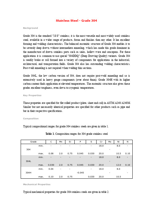
Stainless Steel - Grade 304BackgroundGrade 304 is the standard "18/8" stainless; it is the most versatile and most widely used stainless steel, available in a wider range of products, forms and finishes than any other. It has excellent forming and welding characteristics. The balanced austenitic structure of Grade 304 enables it to be severely deep drawn without intermediate annealing, which has made this grade dominant in the manufacture of drawn stainless parts such as sinks, hollow-ware and saucepans. For these applications it is common to use special "304DDQ" (Deep Drawing Quality) variants. Grade 304 is readily brake or roll formed into a variety of components for applications in the industrial, architectural, and transportation fields. Grade 304 also has outstanding welding characteristics. Post-weld annealing is not required when welding thin sections.Grade 304L, the low carbon version of 304, does not require post-weld annealing and so is extensively used in heavy gauge components (over about 6mm). Grade 304H with its higher carbon content finds application at elevated temperatures. The austenitic structure also gives these grades excellent toughness, even down to cryogenic temperatures.Key PropertiesThese properties are specified for flat rolled product (plate, sheet and coil) in ASTM A240/A240M. Similar but not necessarily identical properties are specified for other products such as pipe and bar in their respective specifications.CompositionTypical compositional ranges for grade 304 stainless steels are given in table 1.T able 1. Composition ranges for 304 grade stainless steelMechanical PropertiesTypical mechanical properties for grade 304 stainless steels are given in table 2.T able 2. Mechanical properties of 304 grade stainless steelPhysical PropertiesTypical physical properties for annealed grade 304 stainless steels are given in table 3.T able 3. Physical properties of 304 grade stainless steel in the annealed conditionGrade Specification ComparisonApproximate grade comparisons for 304 stainless steels are given in table 4.T able 4. Grade specifications for 304 grade stainless steelPossible Alternative GradesPossible alternative grades to grade 304 stainless steels are given in table 5.T able 5. Possible alternative grades to 304 grade stainless steelCorrosion ResistanceExcellent in a wide range of atmospheric environments and many corrosive media. Subject to pitting and crevice corrosion in warm chloride environments, and to stress corrosion cracking above about 60°C. Considered resistant to potable water with up to about 200mg/L chlorides at ambient temperatures, reducing to about 150mg/L at 60°C.Heat ResistanceGood oxidation resistance in intermittent service to 870°C and in continuous service to 925°C. Continuous use of 304 in the 425-860°C range is not recommended if subsequent aqueous corrosion resistance is important. Grade 304L is more resistant to carbide precipitation and can be heated into the above temperature range.Grade 304H has higher strength at elevated temperatures so is often used for structural and pressure-containing applications at temperatures above about 500°C and up to about 800°C. 304H will become sensitised in the temperature range of 425-860°C; this is not a problem for high temperature applications, but will result in reduced aqueous corrosion resistance.Heat TreatmentSolution Treatment (Annealing) - Heat to 1010-1120°C and cool rapidly. These grades cannot be hardened by thermal treatment.Stress Relief Annealing: Cold worked parts should be stress relieved at 750°F (399°C) for 1/2 to 2 hours.WeldingExcellent weldability by all standard fusion methods, both with and without filler metals. AS 1554.6 pre-qualifies welding of 304 with Grade 308 and 304L with 308L rods or electrodes (and with their high silicon equivalents). Heavy welded sections in Grade 304 may require post-weld annealing for maximum corrosion resistance. This is not required for Grade 304L. Grade 321 may also be used as an alternative to 304 if heavy section welding is required and post-weld heat treatment is not possible.MachiningA"Ugima" improved machinability version of grade 304 is available in bar products. "Ugima" machines significantly better than standard 304 or 304L, giving higher machining rates and lower tool wear in many operations.Dual CertificationIt is common for 304 and 304L to be stocked in "Dual Certified" form, particularly in plate and pipe. These items have chemical and mechanical properties complying with both 304 and 304L specifications. Such dual certified product does not meet 304H specifications and may be unacceptable for high temperature applications.ApplicationsTypical applications include:∙Food processing equipment, particularly in beer brewing, milk processing & wine making.∙Kitchen benches, sinks, troughs, equipment and appliances∙Architectural panelling, railings & trim∙Chemical containers, including for transport∙Heat Exchangers∙Woven or welded screens for mining, quarrying & water filtration∙Threaded fasteners∙SpringsSource: Atlas Steels AustraliaFor more information on this source please visit Atlas Steels Australia。
304StainlessSteel
304StainlessSteel304 Stainless SteelCategories:Metal; Ferrous Metal; Heat Resisting; Stainless Steel; T 300 Series Stainless SteelMaterial Notes:Austenitic Cr-Ni stainless steel. Better corrosion resistance than Type 302. High ductility, excellent drawing, forming, and spinning properties. Essentially non-magnetic, becomes slightly magnetic when cold worked. Low carbon content means less carbide precipitation in the heat-affected zone during welding and a lower susceptibility to intergranular corrosion.Applications: beer kegs, bellows, chemical equipment, coal hopper linings, cooking equipment, cooling coils, cryogenic vessels, dairy equipment, evaporators, flatware utensils, feedwater tubing, flexible metal hose, food processing equipment, hospital surgical equipment, hypodermic needles, kitchen sinks, marine equipment and fasteners, nuclear vessels, oil well filter screens, refrigeration equipment, paper industry, pots and pans, pressure vessels, sanitary fittings, valves, shipping drums, spinning, still tubes, textile dyeing equipment, tubing.Corrosion Resistance: resists most oxidizing acids and salt spray.UNS S30400; AMS 5501, 5513, 5560, 5565; ASME SA182, SA194 (8), SA213, SA240; ASTM A167, A182, A193, A194 Key Words:aisi304, AISI 304, T304, T 304, SUS304, SS304, 304SS, 304 SS, UNS S30400, AMS 5501, AMS 5513, AMS 5560, AMS 5565, AMS 5566, AMS 5567, AMS 5639, AMS 5697, ASME SA182, ASMESA194 (8), ASME SA213, ASME SA240, ASME SA249, ASME SA312, ASME SA320 (B8), ASMESA358, ASME SA376, ASME SA403, ASME SA409, ASME SA430, ASME SA479, ASME SA688,ASTM A167, ASTM A182, ASTM A193, ASTM A194, ASTM A666, FED QQ-S-763, MILSPEC MIL-S-5059, SAE 30304, DIN 1.4301, X5CrNi189, B.S. 304 S 15, EN 58E, PN 86020 (Poland), OH18N9, ISO4954 X5CrNi189E, ISO 683/13 11, 18-8Vendors:Click here to view all available suppliers for this material.Please click here if you are a supplier and would like information on how to add your listing to thismaterial.PhysicalPropertiesMetric English CommentsDensity 8.00 g/cc0.289 lb/in3MechanicalPropertiesMetric English CommentsHardness,Brinell123123Converted from Rockwell B hardness.Hardness,Knoop138138Converted from Rockwell B hardness.Hardness,Rockwell B7070Hardness,Vickers129129Converted from Rockwell B hardness.TensileStrength,Ultimate505 MPa73200 psiTensile Strength, Yield215 MPa@Strain 0.200 %31200 psi@Strain 0.200 %Elongation at Break 70.0 %70.0 %in 50 mmModulus of Elasticity 193 - 200 GPa28000 - 29000 ksiPoissons Ratio 0.2900.290Charpy Impact 325 J 240 ft-lb Shear Modulus 86.0 GPa 12500 ksiElectrical Properties MetricEnglishCommentsElectrical Resistivity 0.0000720 ohm-cm@Temperature 20.0 °C0.0000720 ohm-cm@Temperature 68.0 °F0.000116 ohm-cm@Temperature 650 °C0.000116 ohm-cm@Temperature 1200 °FMagnetic Permeability 1.008 1.008at RTThermal Properties Metric English CommentsCTE,linear17.3µm/m-°**********************°C9.61µin/in-°F@Temperature32.0-212°F17.8µm/m-°**********************°C9.89µin/in-°*********************°F 18.7 µm/m-°C@Temperature 0.000 - 650 °C 10.4 µin/in-°F@Temperature 32.0 - 1200 °FSpecific Heat Capacity0.500J/g-°**********************°C0.120BTU/lb-°*********************°FThermalConductivity16.2W/m-**********************°C112BTU-in/hr-ft2-°*********************°F21.5 W/m-K@Temperature 500 °C149 BTU-in/hr-ft2-°F@Temperature 932 °FMelting Point 1400 - 1455 °C2550 - 2651 °FSolidus 1400 °C 2550 °F Liquidus 1455 °C2651 °FComponent Elements Properties MetricEnglishCommentsCarbon, C <= 0.080 %<= 0.080 %Chromium,Cr18.0 - 20.0 %18.0 - 20.0 %Iron, Fe 66.345 - 74.0 %66.345 - 74.0 %Manganese,Mn<= 2.0 %<= 2.0 %Nickel, Ni 8.0 - 10.5 %8.0 - 10.5 %Phosphorous,<= 0.045 %<= 0.045 %PSilicon, Si <= 1.0 %<= 1.0 %Sulfur, S <= 0.030 %<= 0.030 %References for this datasheet.Some of the values displayed above may have been converted from their original units and/or rounded in order to display the information in a consistent format. Users requiring more precise data for scientific or engineering calculations can click on the property value to see the original value as well as raw conversions to equivalent units. We advise that you only use theoriginal value or one of its raw conversions in your calculations to minimize rounding error. We also ask that you refer to MatWeb's terms of use regarding this information. Click here to view all the property values for this datasheet as they were originally entered into MatWeb.。
- 1、下载文档前请自行甄别文档内容的完整性,平台不提供额外的编辑、内容补充、找答案等附加服务。
- 2、"仅部分预览"的文档,不可在线预览部分如存在完整性等问题,可反馈申请退款(可完整预览的文档不适用该条件!)。
- 3、如文档侵犯您的权益,请联系客服反馈,我们会尽快为您处理(人工客服工作时间:9:00-18:30)。
J O U R N A L O F M A T E R I A L S S C I E N C E36(2001)1015–1026Corrosion of TP347H FG stainless steelin a biomassfired PF utility boilerC.LIU,J.A.LITTLEDepartment of Materials Science and Metallurgy,Pembroke Street,Cambridge CB23QZ,UK E-mail:c1120@P.J.HENDERSON,PER LJUNGVattenfall AB,Jamtlandsgatan99,16287Stockholm,SwedenDetailed microscopic examinations have been conducted on two,temperature-regulated probes which had been exposed to biomassflue gas inside a PF boiler for3770h at600◦and650◦C respectively.The two probes were made from commercial grade heat exchanger alloy(TP347H FG).A significant buildup of potassium chloride and sulphate was found on both probes within the deposits that sinter more strongly on the650◦C probe.Both probes suffer extensive intergranular corrosion as well as general corrosion.The higher temperature enhances scale formation which may provide a beneficial effect with respect to hot corrosion resistance.The intergranular corrosion is linked to the presence of sulphur. The overall material wastage is almost the same for both probes and for different locations covered by deposit.C 2001Kluwer Academic Publishers1.IntroductionThere is an increasing interest within the electricity supply industry for more fuelflexibility and the com-bustion of non-conventional fuels such as waste and biomass instead of coal or oil.This is both to reduce CO2emissions and to provide an alternative to dump-ing of waste.In addition,an improvement in electrical efficiency can be gained by increasing the steam tem-perature,which leads to more economic fuel utilisation. Burning of biomass causes widespread superheater cor-rosion,caused by the deposition of alkali chlorides on superheaters with a metal temperature of500◦C or higher.However,most corrosion testing of boiler tubes has been performed in coal-fired environments and,in comparison,relatively little is known about the deposits or corrosion caused by biomass combustion,either at conventional steam temperatures of around550◦C or higher temperatures as anticipated in the future.At least nine elements are recognised in the literature to contribute to overall deposit chemistry in biomass co-fired boilers[1]:O,Si,Al,Fe,Ca,Na,K,Cl and S,with several others playing minor roles such as Ti,Mg,P and C.They may be present in various chemical forms with silicates,oxides,chlorides,and sulphates being the most common.Alkali metals(K and Na)are known to promote fouling and slagging[2].Different mecha-nisms of alkali metal release have also been identified depending on fuel composition and combustion temper-ature[3],involving potassium/sodium sulphate,chlo-ride,hydroxide or cyanate.Of the multiple stages that occur during biomass combustion,char combustion is the most relevant stage in alkali metal release.Released alkali metals form deposits on cooler surface of furnace components made from alloys,ceramics and refractory materials,causing severe loss in heat transfer efficiency and also materials degradation.The primary processes responsible for deposition have been identified as:in-ertial impaction,thermophoretic deposition,conden-sation and chemical reaction.Chlorine released dur-ing combustion mainly facilitates the mobility of many species,in particular potassium,and therefore a high concentration of potassium chloride is often found in pared to other fuels(e.g.,coal),biomass has a higher concentration of alkalis and therefore se-vere slagging and corrosion problems are expected[4]. Higher levels of silica and,to a lesser extent alumina, are likely to reduce corrosion.The alkali salts becomes “sticky”because of the increasing temperature gradient across the deposits and,as a consequence,morefly ash particles are captured.Thermal dissociation and other reactions of the ash compounds also occur resulting in the formation of low melting point slags once the local concentration reaches the eutectic points[5,6]. These molten slags are capable of destroying the pro-tective oxide scales commonly formed on commercial heat exchanger alloys throughfluxing reactions leading to catastrophic corrosion[7,8].As a joint initiative funded by the European Union, collaborative efforts are currently being undertaken to understand the consequence of biomass co-combustion on fouling,slagging and corrosion of commercial heat exchanger alloys.The metallurgical study reported here is a part of the programme.Probe samples have been exposed to biomassflue gas for3770h inside a PF boiler operated at Vattenfall AB;two probe sections in the form of tube rings were subsequently selected for examination.The temperatures of the two probes were controlled at600◦C and650◦C respectively to0022–2461C 2001Kluwer Academic Publishers1015Figure 1A schematic showing the positions of the two types of deposits on the probes and the positions for subsequent XRD and SEM analysis.simulate 550and 600◦C steam.The metal surfaces were heated by the flue gases of 800to 950◦C and cooled internally by pressured air.The temperatures were monitored through three thermocouples inserted into the middle (120degree between them)of the tube wall and were maintained for about 95%of the test pe-riod.The tube alloy was commercial grade TP 347H FG stainless steel and Table I lists its compositions.Detailed information about the biomass fuel (a 100%pulverised wood)and its fly ash/flue gas analysis are given in Tables II–IV ,respectively.The original probe position inside the flue gas passage is shown in Fig.1,together with illustrated locations where X-ray diffrac-tion (XRD)and metallographic (optical and electron)samples were taken for examination.XRD measure-ments were carried out on the probe surface with the deposit attached,whereas the metallographic examina-tions were mainly on the cross sections of both the tube alloy and the deposit.These locations were chosen to give a representative overview of the material wastage information on the probe.Corrosion morphologies found on these retrieved corrosion probes (described later)show the characteris-tics of hot corrosion at relatively low temperature (the so-called Type II hot corrosion)[9,10].This is usu-ally attributed to the formation of low melting point complex salts between sulphates from the deposits and metal elements from the alloy [9–12].The detailed mechanism of this type of hot corrosion remains un-T A B L E I Chemical composition (wt%)of TP 347H FG alloy Elements C Si Mn P S Cr Ni Composition0.090.391.500.0240.00118.511.95T A B L E I I Analysis of the biomass fuel SCA (heating value of 20.549MJ kg −1)Composition (wt%)SiO 2Al 2O 3CaO Fe 2O 3K 2O MgO Na 2O Ash (%)C (%)H (%)O (%)SCA0.04650.01030.1260.01190.03880.02310.01720.3847.66.142.9Other trace elements (in ppm level):As,Ba,Be,Cd,Co,Cr,Cu,Hg,La,Mo,Nb,Ni,Pb,Sc,Sn,Sr,V ,W,Y ,Zn,Zr.T A B L E I I I Analysis of the fly ash from the 100%wood fuel Composition (wt%)SiO 2Al 2O 3CaO Fe 2O 3K 2O MgO Na 2O S (ppm)Cl SCA14.1 2.920.7 2.78.14.01.0155001.7Other minor elements analysed but not listed:P 2O 5,TiO 2and MnO 2,as well as those trace elements listed in the fuel analysis (Table II).T A B L E I V Average flue gas analysisFuel HCl (ppm)SO 2(ppm)CO (ppm)CO 2(%)O 2(%)NO (ppm)SCA 41010155101clear,even under coal combustion conditions [13].For Type II hot corrosion under biomass deposits that is usually rich in alkali chlorides,accelerated ‘active’ox-idation by forming volatile metal chlorides has been proposed to be a possible mechanism [14–16],but this remains to be confirmed by both laboratory studies and industrial trials.2.Result and discussionVisually there seems to be two types of deposit:the first type (Type I)has a dark brown colour,similar to the colour of the fly ash.It forms on a narrow region of the probe surface (directly facing the flue gas passage)and is generally thicker (ca.2mm at the thickest point,gradually becoming thinner)than the second type.This type (Type II)has a light grey or light brown colour and is relatively uniform in thickness (estimated to be about 0.5–1mm).It covers about 2/3of the tube surface.Be-tween the areas covered by the two types of deposits there are two bands (along the axis of the probe)on the probe surface that have very little deposit.The deposits appear to be well sintered on the probe,particularly the Type II deposit.There may be more deposits on the original probes that are less well sintered and there-fore lost during handling.There is no obvious differ-ence in either the colour or the thickness of the deposit at the two temperatures by visual ing op-tical microscopy,the maximum metal loss measured from the 600◦C sample was 77±5µm and from the 650◦C sample it was 88±5µm.The inner surface of the two probes had a negligible oxidation loss of less than 10±3µm for both temperatures.Therefore,there seems to be no significant difference between the two probes in terms of material wastage.2.1.XRD measurementResults from the two samples are shown in Fig.2a and b respectively.For the 600◦C probe (Fig.2a),KCl and1016Figure2XRD spectra for the600◦C(a)and the650◦C probes(b).For corresponding position of each spectrum,please refer to Fig.1.The three strongest peaks for each species are also labelled on the spectra.K2SO4are the two substances clearly detected at al-most all locations.As the location changes from X1to X4,there is a gradual increase of the intensity of the reflection from these compounds and then a decline at location X5.This suggests that a significant proportion of the Type II deposit is made of KCl and K2SO4.An-other reason for the increased intensity of the reflections is that the deposit at the locations X1to X4becomes denser or more crystalline,which may contribute to an enhanced degree of sintering from X1and X4.Like-wise,the spectrum at X1has lower counts and this may be the result of a loosely sintered deposit.The spectrum from position X2also has peaks showing the possible presence of NiO and NiFe2O4.This is expected for X2, as it has almost no deposit(Fig.1)and hence experi-ences an environment giving simply oxidation,unlike the other positions.X5shows low intensities,similar to that of X1,but with slightly stronger KCl peaks.In general,the peak intensity as detected by XRD is a com-bined result of concentration,crystallinity and surface roughness.The deposit at X5appears more porous(e.g., than X3or X4),possibly because it is at the back of the probe,relative to the direction offlue gas,and hence its formation may involve a different deposition mech-anism.Other possible,but minor species suggested by XRD include:FeS,FeO(OH),Fe3O4,Al2O3,Ca2V2O7, P2O5,Wollastonites(CaSiO3,Ca3SiO5,etc.),CaCO3 and K2CO3.The percentages of these species in the deposit,if they are detected,are very small.For ox-idative corrosion products,iron oxides and NiO(and NiFe2O4)are detected at the location X2and possibly exist at other locations as well;chromium oxide is not observed.This however does not imply that chromium oxide is not formed under these conditions(as will be shown later)as chromium oxide and other chromium species are usually formed beneath the iron or nickel oxides,and hence their detection is restricted by the penetration depth of the X-ray source(Cu-Kαpene-trates less than50µm for polycrystalline materials). Similarly,other reaction products between the deposit and the alloy may also not be detected if they grow deeper into the alloy substrate.For the650◦C probe(Fig.2b),the overall trend is quite similar to that observed in Fig.2a.One clear trend,as compared to the600◦C probe,is that the rela-tive intensity of K2SO4to KCl is increased,indicating a higher concentration of sulphates at higher temper-atures,in particular at the locations from X3to X5. In addition,the peaks for NiO and NiFe2O4(possibly Fe2O3,FeCr2O4)are also stronger,which suggests en-hanced oxidation.Again there is the same trend of an increase in KCl intensity when the location is changed from X1to X4and a further reduction from X4to X5. The only difference between Fig.2a and b is that at X5 the dominant species seems to be the sulphate for the 650◦C probe rather than KCl as on the600◦C probe.2.2.Microscopic examinationTypical sections of the probe were cut by hand in or-der to minimise damage to the deposits.After mount-ing with a conductive resin,cross sections of the probes were prepared for metallographic examination. Scanning electron microscopy equipped with energy-dispersive X-ray analysis(SEM/EDX)was carried out. Typical results for the600◦C probe are summarised in Fig.3on half of the probe.For easier description and comparison of the material lost through corrosion, there characteristic layers are identified in Fig.3to-gether with the locations for SEM/EDX analysis.The first characteristic layer(Layer I)forms the outermost scale,which is roughly parallel to the remaining metal surface and may be covered with sintered deposits.The second characteristic layer(Layer II)is the interme-diate scale layer,which is often physically separated from Layer I and has the appearance of general corro-sion.Unreacted alloy can sometimes be found within this layer.Finally,the third characteristic layer is an in-ternal corrosion layer(Layer III),which has clearly re-sulted from intergranular corrosion.These features are found to exist for both the600◦C and650◦C probes, although to a different extent.Detailed micrographs at various locations are shown in Fig.3a to f.Apart from Fig.3f(which is from the backside of the probe),the rest of the probe surface suffers a similar extent of corrosion featuring the three characteristic layers.A complete Layer I is not always observed for all of the locations;this is shown in Fig.3c and3e where the remaining Layer I seems detached from the underlaying yer I often appears less dense and mixed with the ash components(Fig.3c).The dominant corrosion reactions in these environments would be oxidation,hot corrosion by molten deposits (mainly chlorides and sulphates as shown by the XRD measurements),plus possible gas-phase sulphidation and chlorination.The broken and less adherent Layer I therefore offers little barrier to the ingress of either1017Figure 3SEM micrographs prepared on the cross sections of the 600◦C probe.gaseous reactants or molten slag towards the remain-ing tube material.This point may be further illustrated by Fig.3c:the micrograph shows two regions with the right-side Layer I much thicker than the left-side and this difference appears not to be caused by broken scale on the left-side as both have a thick deposit layer formed on top.It is interesting to note that this large differencein Layer I has apparently very little influence on ei-ther the morphology or the thickness of the remaining layers formed beneath (Layers II and III).Despite the care taken during the sample preparation,some loss of deposits is still inevitable with the only micrograph to show extensive deposits being Fig.3c.The corrosion reaction between the deposits and the metal therefore1018bypasses Layer I and continues via grain boundaries and leads to the growth of the other two pletely or partially consumed grains then become Layer II.Fig.3f is a somewhat exceptional case as it does not seem to follow the classification of three lay-ers.It has no visible scale layer,although it is likely that the original Layer I may have been lost during sample preparation.The major difference is the appearance of the intergranular corrosion layer,which is shallower,wider and also less concentrated at grain boundaries,hence giving an appearance more like pitting.The over-all depth of corrosion (without taking into Layer I into account),however,is similar to the other positions.Fig.4shows EDX results across the three charac-teristic layers (the scale)found at a location close to Fig.3d (most of the deposit has been lost).As shown in Table V,the clearest trend seems to be the distribu-tion of chromium,which shows a decrease towards the outer surface.This is usually associated with its slow diffusion rate relative to iron and nickel,which leads to an enrichment of chromium at the inner scale and forms the basis for enhanced corrosion protection.Hot corrosion at the grain boundaries,as shown in Fig.3,is more detrimental,because it penetrates this chromium-rich oxide layer and reduces the possibility of forming a continuous protective layer.Higher iron and nickel contents in Layer I are also evident,although some iron may come from the deposit.The highest sulphur level is at Point 3and the implication is that sulphur is con-centrated in Layer II and its source is the deposit.De-spite the high concentration of KCl detected by XRD in Fig.2a,very little chloride is in fact detected within the scale.This result may be explained by an acceleratedT A B L E V EDX analysis of the 600◦C sample Elements Point 1Point 2Point 3Point 4O 20.118.711.8 1.0Fe 63.858.6 3.368.2Na 00.700K 0.3 3.60.90.2Ca 0.20.40.30Mg 00.200.1Cr 3.97.337.117.8Mn 5.0 4.9 4.9 1.7Ni 6.1 4.535.411.6Si 0.20.1 1.70.6P 000.10.1S 0.10.6 4.00.3Al0.10.1Figure 4A typical cross section on the 600◦C probe and the results of EDX analysis (Table V)carried on the corresponding positions.“active oxidation”as discussed by Grabke et al.[6]:es-sentially volatile metal chlorides are formed as a result of chlorination and this is followed by re-oxidation on their way to the surface.The chloride level remained within the scale is too low to be detected by EDX,in contrast to the high concentration of KCl in the deposit as detected by XRD.The EDX analysis on the probe alloy itself (Point 4)gives the following results (wt%):68.3Fe,11.6Ni,17.7Cr,1.7Mn,0.59Si,which is very close to the original composition of the probe alloy (Table I).An averaged composition analysis as shown in Fig.4is less informative when intergranular corrosion has oc-curred.A more informative analysis is shown in Fig.5,which is a collection of elemental X-ray maps for the major elements involved in the intergranular corrosion reactions.As shown by Fig.5,the grain boundaries are generally enriched with chromium and partially with nickel but depleted in iron.The chromium dis-tribution along the grain boundaries is closely matched by oxygen,suggesting the formation of chromium ox-ides here.More iron can be found in the general cor-rosion layer,together with nickel.Sulphur is also seen along the grain boundaries,which is closely linked with the nickel distribution,suggesting that the initial cor-rosion at the grain boundaries involves the formation of nickel-sulphur compounds,possibly Ni 3S 2,NiS or NiS 2.Three characteristic areas are located on the SEM micrograph in Fig.5,marked by A,B and C,rep-resenting different extents of intergranular corrosion.The grain boundary at the area A has a clear band of chromium oxide layer surrounding a nickel and iron centre;the nickel centre is also oxygen deficient but may be enriched with sulphur.Grain boundary corro-sion at the location B occupies a much wider area as compared to A and is thus at a more advanced stage of corrosion.Area B has the highest chromium and oxygen intensity and the nickel and iron distribution is relatively isolated and patchy.Similar areas like B can also be identified within Layer II.This possibly represents those areas where there is significant accu-mulation of chromium together with a high enough oxygen partial pressure to form and maintain a sta-ble chromium oxide.Nevertheless,as shown by the chromium map this chromium oxide layer is far from coherent and uniform.Area C,which corresponds to the designated general corrosion layer,shows a mixture of phases seen in areas A and B.Some are significantly depleted in chromium with rather high concentrations of iron (and oxygen),and others show the bined with the EDX results in Fig.4,it seems that the outer scale layer (Layer I)is mainly iron oxides plus a small quantity of nickel compounds.The general cor-rosion layer (Layer II)is a mixture of chromium oxide,iron oxide and isolated nickel sulphides and oxide,with clearly segregated boundaries.Finally,the forefront of the intergranular corrosion occurs through oxidation and sulphidation of iron and nickel,leaving chromium to form chromium oxide.The oxide ion concentration is linked to the oxygen partial pressure,which in turn is known to be a function of the SO 2-SO 3equilibrium that also controls the sulphidation reaction [7].The chlorine map gives a uniform distribution across the region and1019Figure5Elemental mapping carried out around the regions where intergranular corrosion takes place on the600◦C sample.The location is from the sample shown in Fig.3a.1020is,hence,omitted here.It seems that the intergranular corrosion is almost the exclusive result of sulphidation and independent of the strong presence of KCl in the deposit.Possible roles played by chlorinationwhere Figure 6SEM micrographs prepared on the cross sections of the 650◦C probe.The position for each photo on the probe surface is given in Fig.3.there is a chloride or HCl (in the presence of moisture)partial pressure (Table IV)remain to be investigated.Fig.6shows micrographs from the 650◦C probe at similar locations to those on the 600◦C probe (Fig.3).It1021can be seen that the deposits on the 650◦C probe appear to be more adherent,possibly because of the increased sintering at the higher temperature.Fig.6a shows that,at the location directly facing the flue gas,a thick and dense deposit layer is formed.In particular,it seems to have a “crusted cover”on the outer surface.Fig.6a is a higher magnification of this deposit/scale interface,which reveals the extent of scale growth and intergran-ular corrosion.It also confirms the well-sintered nature of the deposit.The enhanced sintering of the deposit on the 650◦C probe is also obvious by examining micro-graphs from the other locations (Fig.6c to e),as almost all show a thick ash layer.Fig.6b comes from the lo-cation between the two types of deposits where there is almost no parison between Figs 3b and 6b shows that the oxidation layer (Layer 1)at 650◦C is much denser and more yer II in Fig.6is nearly identical to Fig.3and the extent of intergranular corrosion seems less.There is also very little variation between the different locations at 650◦C even at the back location (Fig.6f).Fig.7shows the EDX analysis from different points of the deposit layer shown in Fig.6a.A significant en-richment of calcium and silicon at the outer deposit (the crust)is clearly visible,and this is accompanied by marked decrease of sodium within this -pared to the original fly ash composition (Table III),the Ca/K ratio is roughly the same for the crust (Point 1)but significantly less for the deposit within it (Points 2and 3)(Table VI).This indicates that the crust is com-posed mainly of fly ash particles,which subsequently undergo chemical reactions themselves and with the underlying oxide scale.The overall result is that the deposit beneath the crust may be molten at operating temperatures and solidify upon cooling.Aluminium is fairly constant throughout the deposit layer.From Point 1to 3,a slight increase of iron and sulphur is also de-tected which may coincide with the K 2SO 4picked upbyFigure 7A cross section on the 650◦C probe directly facing the flue gas and the EDX results (Table VI).Point 4was not included in the table as the region consists of both deposit and scale.T A B L E V I EDX analysis of the deposit on the 650◦C sampleThe curst The middle ash The inner ash Elements (Point 1)layer (Point 2)layer (Point 3)O 25.633.536.8Fe 0 1.60Na 3.313.214.2K 17.426.027.1Ca 37.213.713.8Mg 3.3 2.2 1.6Ti 0.9 3.10.3Cr 00.30.2Mn 4.0 3.2 2.7Ni 000Al 1.4 1.0 1.4Si 5.00.90.8P 1.20.90.7S 0.60.20.2Cl0.10.10.1XRD (Fig.2b).EDX mapping of this area was carried out and the results are shown in Fig.8.Fig.8reveals the enrichment of calcium,magnesium and phosphorus at the outer crust,accompanied by a slight increase of silicon and possibly sulphur.Sodium is enriched at the deposit/metal interface.However,EDX does not reveal the presence of chloride at this cross ing dry grinding to minimise the loss of the deposit,Fig.9shows a cross section on the 650◦C probe at the loca-tion of Fig.6e together with EDX mapping of the main ash and scale paring Fig.9with Fig.8reveals entirely different trends of the ash elements:there is no obvious preferential distribution of the ash elements in Fig.9.Calcium,potassium and sulphur are all seen over the whole deposit.Broadly speaking,the clear presence of chloride (mainly as KCl)agrees well with the XRD results shown earlier.More specifically,it seems that that the chloride is accumulated next to the scale but hardly any within the scale.The scale consists essentially of iron oxide on top of chromium oxide.The main conclusion here is that the composition of the de-posit formed on the probe ring depends on their relative location to the flue gas direction.The results in Figs 5,8and 9seem to agree with the theoretical phase stability diagrams of nickel,chromium and iron in the gaseous mixture of oxy-gen/sulphur and oxygen/chlorine,as shown in Fig.10(using 600◦C as an example).In Fig.10a,the area marked as A gives the gas partial pressures where it is thermodynamically possible to form nickel sulphide mixed with chromium oxide and iron oxide.Similarly as shown in Fig.10b,unless a quite large chlorine partial pressure exists there would be very little possibility for the formation of chromium and iron chlorides.All these situations could represent the local environment at area A in Fig.5,which is responsible for the initiation of in-tergranular corrosion.The areas B and C in both Figs 5and 10correspond to an increased oxygen partial pres-sure,therefore favouring the formation of oxides for all three elements.The outer,general corrosion layer (Layer I)sees the environment marked as D in Fig.10with the highest oxygen,sulphur and chlorine partial pressure and is directly in contact with molten deposit,10221023which was in turn in equilibrium with the flue gas (Table IV).Therefore,fluxing reactions are most likely to dominate at these locations.A recent study by Aste-man et al.[8]also suggests a possible linkbetween Figure 9Elemental mapping of main ash as well as alloy elements across the deposit and the scale on the 650◦C probe located roughly position Fig.6e.(Continued )chromium depletion at the outer general corrosion layer with the presence of moisture through the formation of volatile CrO 2.H 2O gas under similar situations.Area D in both Fig.10a and b overlaps with the CrO 2domain,1024Figure 9(Continued).Figure 10Theoretical phase stability diagram of nickel,chromium and iron in the gas mixture of oxygen/sulphur (a)and the oxygen/chlorine (b)at 600◦C.which itself has a theoretical melting point of 300◦C,thus also confirming the possible reaction conditions at area D.In summary,the increased temperature appears to have two major effects.Firstly,it enhances the sin-tering tendency of the deposits.It is very likely that this makes the deposits more “sticky”at the operating temperature,thus reflecting the aggravated problems of slagging.Secondly,oxidation of the alloy increases at the same time and this helps to develop a denser and more adherent oxide scale and thus minimise the extent of intergranular corrosion.The fact that this more pro-tective oxide layer remains under the sintered deposits will offer enhanced corrosion protection.Despite dif-ferent locations at 650◦C (Fig.6a to f),there is very little difference in the thickness of either the outer cor-rosion layer (Layer I)or the other two layers (Layer II and III).3.SummaryThe only variable between the two probes is the temper-ature.Increased temperature seems to cause a higher degree of sintering of the deposit,hence promoting slagging.The effect on the corrosion of the tube can be judged on the average material wastage over the test period (3770h).The results suggest that increased temperature is important in determining the ash chem-istry,the sintering behaviour and the alloy’s ability to grow and repair its oxide layer under the deposit.These parameters will affect both the operational procedures and the service life of the tube metal.Experiments as a function of the reaction time and a wider temperature range are currently being undertaken.As the thickness of the deposits around the tube is not constant,this may imply a variable temperature gradient across the deposit,which may influence the sintering tendency and possibly corrosion.In practice,there may also be a temperature difference between upstream side and downstream side.For laboratory hot corrosion tests utilising synthetic ashes,the observed accumulation of potassium chloride in the deposits,far exceeding the level in its original fly ash,will be very important.To simulate accurately deposit induced hot corrosion,the synthetic ash composition must contain a substantially higher amount of potassium chloride than that in the fly ash.AcknowledgementThe authors thank the European Commission for fund-ing this work within the framework of the Non-Nuclear Energy Programme (JOULE III)and the co-ordinator of the project at the Institute of Process Engineering and Power Plant Technology (IVD),University of Stuttgart,Germany.References1.B .M .J E N K I N S ,L .L .B A X T E R ,T .R .M I L E S and T .R .(J R .)M I L E S ,Fuel Processing Technology 54(1998)17.2.L .L .B A X T E R ,Biomass and Bioenergy 4(1993)85.3.D .C .D A Y T O N ,R .J .F R E N C H and T .A .M I L N E ,Engery and Fuels 9(1995)855.4.T .R .M I L E S ,T .R .(J R .)M I L E S ,L .L .B A X T E R ,R .W .B R Y E R S ,B .M .J E N K I N S and L .L .O D E N ,Biomass and Bioenergy 10(1996)125.1025。