3300中文手册8
本特利振动探头中文说明书
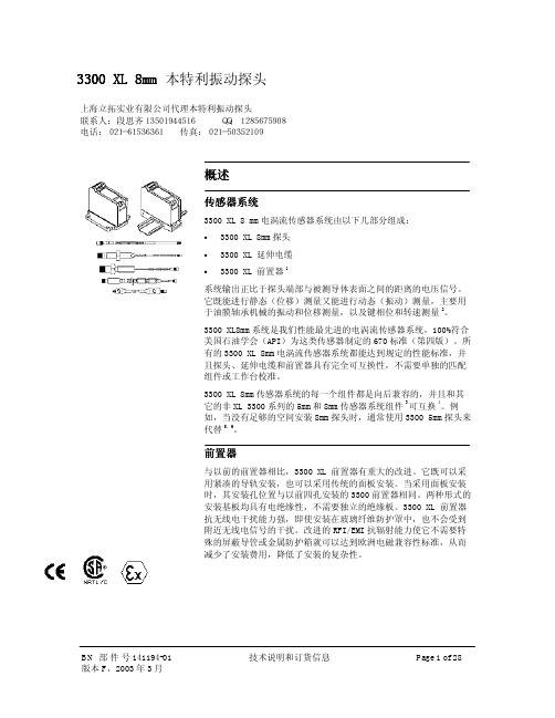
3300 XL 8mm 本特利振动探头概述传感器系统3300 XL 8 mm 电涡流传感器系统由以下几部分组成:• 3300 XL 8mm 探头 • 3300 XL 延伸电缆 •3300 XL 前置器1系统输出正比于探头端部与被测导体表面之间的距离的电压信号。
它既能进行静态(位移)测量又能进行动态(振动)测量,主要用于油膜轴承机械的振动和位移测量,以及键相位和转速测量2。
3300 XL8mm 系统是我们性能最先进的电涡流传感器系统,100%符合美国石油学会(API )为这类传感器制定的670标准(第四版)。
所有的3300 XL 8mm 电涡流传感器系统都能达到规定的性能标准,并且探头、延伸电缆和前置器具有完全可互换性,不需要单独的匹配组件或工作台校准。
3300 XL 8mm 传感器系统的每一个组件都是向后兼容的,并且和其它的非XL 3300系列的5mm 和8mm 传感器系统组件3可互换4。
例如,当没有足够的空间安装8mm 探头时,通常使用3300 5mm 探头来代替5,6。
前置器与以前的前置器相比,3300 XL 前置器有重大的改进。
它既可以采用紧凑的导轨安装,也可以采用传统的面板安装。
当采用面板安装时,其安装孔位置与以前四孔安装的3300前置器相同。
两种形式的安装基板均具有电绝缘性,不需要独立的绝缘板。
3300 XL 前置器抗无线电干扰能力强,即使安装在玻璃纤维防护罩中,也不会受到附近无线电信号的干扰。
改进的RFI/EMI 抗辐射能力使它不需要特殊的屏蔽导管或金属防护箱就可以达到欧洲电磁兼容性标准,从而减少了安装费用,降低了安装的复杂性。
上海立拓实业有限公司代理本特利振动探头联系人:段思齐13501944516 QQ:1285675908电话:021-61536361 传真:021-503521093300 XL的SpringLoc 端子带不需要特殊的安装工具即可紧固。
由于不需要螺丝紧固,不会发生松动,所以连线更坚固。
迅达电梯3300AP手册.pdf
3 进场准备, 材料接收及井道检查............................................................... 11 3-1 安装工时 ....................................................................................... 11 3-2 进场准备 ....................................................................................... 11 3-3 井道检查 ....................................................................................... 12 3-3-1 常规检查 ............................................................................ 12 3-3-2 特别检查 ............................................................................ 13 3-4 材料接收 ....................................................................................... 16 3-4-1 货物检查与存贮 ................................................................. 16 3-4-2 装箱描述 ............................................................................ 18 3-5 质量检查 ....................................................................................... 19
3300 系统用户手册

FW-3300 系统用户手册System User Manual文档编号:FW-3300-SUM-1.0发布时间:2005-11-9北京立华莱康平台科技有限公司版权所有Copyright © L&S Platform 2005. All right reserved目录0 前言(PREFACE) (3)1 FW-3300系统 (4)1.1 系统简介 (4)1.2 机箱 (4)1.2.1 1U 19英寸机箱 (4)1.2.2 桌面机箱 (5)1.3 电源 (8)2 EM-433主板 (8)2.1 EM-433 主板简介 (8)2.1.1 技术指标 (9)2.1.2布局 (10)2.2 EM-433 接口说明 (11)2.2.1 电源接口 (11)2.2.2 网络接口 (11)2.2.3 串口 (11)2.2.4 PCI接口 (12)2.3 EM-433 使用注意事项 (13)2.3.1 内存容量扩展 (13)2.3.2 Flash容量扩展 (13)2.3.3 主板供电 (13)2.3.4 主板型号 (13)3 FW-3300 软件使用方法 (14)3.1 SDK介绍 (14)3.2 编译系统(如何编译linux) (14)3.2.1编译uClinux (14)3.2.2编译Pmon (14)3.2.3编译bbload (14)3.3 系统启动与配置 (14)3.3.1更新 MAC 地址 (15)3.3.2更新 Pmon (15)3.3.3更新pmon-script (16)3.3.4更新linux (17)3.3.5 Linux下更新系统程序 (18)3.3.6 Pmon-script简介 (19)3.4 FreeSWAN下IPSEC的测试 (20)4 FW-3300测试指标 (22)4.1 路由性能 (22)4.2 IPSEC性能 (22)4.3 Cavium公司官方测试指标 (22)0 前言(PREFACE)0.1 关于本文(About this document)本手册主要描述FW-3300系统的构成,介绍系统主板EM-433的使用方法,系统软件的使用方法及系统测试指标。
LT-3300 系列 安装指南说明书
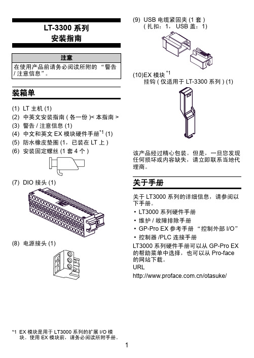
LT-3300系列安装指南装箱单(1)LT 主机(1)(2)中英文安装指南(各一份)<本指南>(3)警告/注意信息(1)(4)中文和英文EX 模块硬件手册*1(1)(5)防水橡皮垫圈(1,已装在LT 上)(6)安装固定螺丝(1套4个)(7)(8)电源接头(1)(9)USB 电缆紧固夹(1套)((10)EX 模块挂钩(仅适用于LT-3300系列) (1)该产品经过精心包装。
但是,一旦您发现任何损坏或内容缺失,请立即联系当地代理商。
关于手册关于LT3000系列的详细信息,请参阅以下手册。
•LT3000系列硬件手册•维护/故障排除手册•GP-Pro EX 参考手册“控制外部I/O ”•控制器/PLC 连接手册LT3000系列硬件手册可以从GP-Pro EX 的帮助菜单中选择,也可以从Pro-face 的网站下载。
URL/otasuke/注意在使用产品前请务必阅读所附的“警告/注意信息”。
*1EX 模块是用于LT3000系列的扩展I/O 模块。
使用EX 模块前,请务必阅读所附手册。
部件名称和功能名称描述A 状态指示灯B DIO 接口(DIO)连接外部I/O 设备的接口C 辅助模块接口/扩展模块(EXT2)用于连接附加模块(通讯功能等)。
D EX 模块接口(EXT1)用于连接Pro-face 制造的EX 模块E 电源接头F 以太网接口(10BASE-T/100BASE-TX)使用RJ-45型Modular Jack 接头(8孔)。
G USB 主机接口(USB)1接口符合USB1.1。
(TYPE-A 连接)电源电压: DC5V ± 5%输出电流: 500mA (最大)最大通讯距离是5米。
H 串口(COM1)D-Sub 9针凸型接头。
通讯方式(RS-232C/RS-422/RS-485)通过软件来切换。
正视图后视图底视图右视图颜色指示灯操作模式(绘图)程序执行模式(启用逻辑程序时)绿ON 离线运行中运行闪烁运行中停止红ON 上电时闪烁运行中严重错误橙ON 背光灯烧毁闪烁软件启动过程中一般规格电气规格环境规格电源输入电压DC24V额定电压DC19.2~28.8V 允许失电3ms 以下功耗27W 以下瞬时电流30A 以下绝缘强度AC1000V 20mA 时1分钟(电源端与FG 端子之间)绝缘电阻DC500V 10M Ω以上(电源端和FG 端子之间)物理工作环境温度0~+50°C *1*1如果在温度为40°C 以上的环境中使用并持续一段时间,人机界面屏幕对比度会有所下降。
3300八组合说明书

7.5 再次按下向右键进入画面 4,显示如下信息:
4
参数整定
项目
参数名称
1 额定电流
2 速断电流倍数
3 运行方式
4 程控前级回路
5 程控自动延时
6 另一低速回路/程控后级回路
7 程控停车延时
8 本机高速回路
9 第一低速回路
10 双速切换时间
接触器 #1 数值
A
0,0s 0,0s
0,0s
在此画面中进行参数设置:按向下或向上键选来选定 1~10 中任意一项;设置每一 项中的参数时,需按确认+向下或向上两键来实现,且操作时先按下确认 2 秒,接着 再按下向下或向上 键来整定,按确认+向下键数值递增,按确认+向上键数值递减。 各回路所需设定参数及基本含义如下表:
2-程控
当本回路为程控运行首回
路时选本回路序号
5 程控起动延时 程控工况时,前级起动 0~40.0S 后,本回路须延时起动 时间
当本回路为程控运行首回 路时选为 1
6 程控后级回路 程控工况时,其后一级 1~6 运行回路序号
另一低速回路 双机双速控制时,设定 1、3、5 另一电机的低速回路
另一高速回路 双 机 双 速 控 制 时 设 定 2、4、6 另一电机的高速回路
7.4 再次按下向右键进入画面 3,显示如下信息:
故障显示 3 漏电闭锁 短路 过载 断相 过压 欠压 通讯 其它 #1 #2 #3 #4 #5 #6 #7 #8 在此画面中,当发生故障后可以显示#1~#8 回路是哪种故障方式。故障排除后除
-6-
“短路”和“其它”两种故障方式需按复位键返回画面 1 运行状态,其余故障方式排除 后将自动返回画面 1 运行状态。 注“其它”故障为上述故障之外的故障。
戴尔 Latitude 3300 安装和规格指南说明书

Dell Latitude 3300Setup and Specifications GuideNotes, cautions, and warningsNOTE: A NOTE indicates important information that helps you make better use of your product.CAUTION: A CAUTION indicates either potential damage to hardware or loss of data and tells you how to avoid the problem.WARNING: A WARNING indicates a potential for property damage, personal injury, or death.© 2019 Dell Inc. or its subsidiaries. All rights reserved. Dell, EMC, and other trademarks are trademarks of Dell Inc. or its subsidiaries. Other trademarks may be trademarks of their respective owners.2019 - 01Rev. A001 Welcome - Getting Started (5)Product overview (5)Chassis Overview (6)Base view (6)Left view (7)Right view (7)Front view (8)Product Comparison (8)2 Technical Specifications (10)Processor (10)Memory (10)Storage (11)System board connectors (11)Media card-reader (11)Audio (11)Integrated graphics (12)Camera (12)Communication (12)Wireless (13)Ports and connectors (13)Display (13)Keyboard (14)Touchpad (14)Operating system (15)Battery (15)Power adapter (16)Dimensions and weight (16)Computer environment (17)Security (17)Security Software (17)3 System setup (19)Boot menu (19)Navigation keys (19)System setup options (20)General options (20)System configuration (21)Video screen options (22)Security (22)Secure boot (25)Intel Software Guard Extensions options (25)Performance (26)Contents3Power management (26)Post behavior (28)Virtualization support (29)Wireless options (29)Maintenance (30)System logs (30)SupportAssist System Resolution (31)Boot Sequence (32)Updating the BIOS in Windows (32)Updating your system BIOS using a USB flash drive (33)Updating the Dell BIOS in Linux and Ubuntu environments (33)System and setup password (34)Assigning a system setup password (34)Deleting or changing an existing system setup password (34)4Contents1Welcome - Getting Started Product overviewThe new Dell Latiude 3300 is next in line to the generation of Latitude 3000 series. This series delivers the highest levels of performance, newest technologies, high levels of configurability, and premium industrial design to students that run specific applications as part of their daily activities. It provides a larger screen and more powerful processor (up to Intel Kaby Lake R Core i5) enabling students to create while also providing a low price point that education customers can afford.Dell Latiude 3300 is a versatile solution that packs the power and performance of a workstation into a class leading portable form factor. The Dell Latitude 3300 is the successor of the Dell Latitude 3380.The Dell Latitude 3300 is the most powerful and feature-rich rugged notebook, that gives users desktop replacement performance in a mobile form factor. The new Latitude 3300 for education delivers the most versatile solution, with best-in-class durability, empowering students to learn.Features:•Kaby Lake U and Kaby Lake R•100% SSD, no spinning Hard Drive•13.3” HD/FHD Non-touch/touch displays•3-cell 42Whr and 4-cell 56Whr batteries•I/O: 2xUSB3.0, HDMI, micro SD 3.0, upsell 1xUSB-C•T ype-C port with Power Delivery (Optional with non-celeron base)Welcome - Getting Started5Chassis OverviewThis chapter consists of the product view features along with technical specifications. The chassis overview features calls out the different ports, connectors, and components available in the computer.Base view1System fan vent2Heatsink vent3SSD vent4Service tag5Speakers6Welcome - Getting Started1Power connector2USB T ype-C port3Network port4HDMI port5USB 3.0 portRight view1Audio port2Battery status light3microSD port4USB 3.0 port5Wedge-shaped lock slotWelcome - Getting Started71Camera2Camera status light 3Microphone4LCD Panel Product ComparisonT able 1. Product comparison with predecessor model8Welcome - Getting StartedWelcome - Getting Started9T echnical SpecificationsProcessorNOTE: Processor numbers are not a measure of performance. Processor availability is subject to change and may vary by region/country.T able 2. Processor specificationsMemoryT able 3. Memory specifications210T echnical SpecificationsStorageT able 4. Storage specificationsSystem board connectorsT able 5. System board connectorsMedia card-readerT able 6. Media-card reader specificationsAudioT able 7. Following are the audio specificationsTechnical Specifications11Integrated graphicsT able 8. Integrated graphics specificationsNOTE: Celeron CPU sku does not have the T ype-C portCameraT able 9. Camera specifications CommunicationT able 10. Communication specifications 12T echnical SpecificationsWirelessT able 11. Wireless specificationsPorts and connectorsT able 12. Following are ports and connectors specificationsDisplayT able 13. Following are the display specificationsTechnical Specifications13KeyboardT able 14. Keyboard specificationsTouchpadT able 15. Touchpad specifications14T echnical SpecificationsOperating systemT able 16. Operating systemBatteryT able 17. Battery specificationsTechnical Specifications15Power adapterT able 18. Power adapter specificationsDimensions and weight T able 19. Dimensions and weight16T echnical SpecificationsComputer environmentNOTE: Airborne contaminant level: G1 as defined by ISA-S71.04-1985.For information on Dell Product Safety, EMC and Environmental Data Sheets, see https:///learn/us/en/uscorp1/product-info-datasheets-safety-emc-environmental .T able 20. Computer environment* Measured using a random vibration spectrum that simulates user environment.† Measured using a 2 ms half-sine pulse when the hard drive is in use.‡ Measured using a 2 ms half-sine pulse when the hard-drive head is in parked position.SecurityT able 21. Security Security SoftwareT able 22. Security Software Technical Specifications 1718T echnical SpecificationsSystem setup CAUTION: Unless you are an expert computer user, do not change the settings in the BIOS Setup program. Certain changes canmake your computer work incorrectly.NOTE: Before you change BIOS Setup program, it is recommended that you write down the BIOS Setup program screen information for future reference.Use the BIOS Setup program for the following purposes:•Get information about the hardware installed in your computer, such as the amount of RAM and the size of the hard drive.•Change the system configuration information.•Set or change a user-selectable option, such as the user password, type of hard drive installed, and enabling or disabling base devices. Topics:•Boot menu•Navigation keys•System setup options•Boot Sequence•Updating the BIOS in Windows•System and setup passwordBoot menuPress <F12> when the Dell logo appears to initiate a one-time boot menu with a list of the valid boot devices for the system. Diagnostics and BIOS Setup options are also included in this menu. The devices listed on the boot menu depend on the bootable devices in the system. This menu is useful when you are attempting to boot to a particular device or to bring up the diagnostics for the system. Using the boot menu does not make any changes to the boot order stored in the BIOS.The options are:•UEFI Boot:–Windows Boot Manager••Other Options:–BIOS Setup–BIOS Flash Update–Diagnostics–Change Boot Mode SettingsNavigation keysNOTE: For most of the System Setup options, changes that you make are recorded but do not take effect until you restart the system.Keys NavigationUp arrow Moves to the previous field.3System setup19Keys NavigationDown arrow Moves to the next field.Enter Selects a value in the selected field (if applicable) or follow the link in the field.Spacebar Expands or collapses a drop-down list, if applicable.T ab Moves to the next focus area.NOTE: For the standard graphics browser only.Esc Moves to the previous page until you view the main screen. Pressing Esc in the main screen displays a message that prompts you to save any unsaved changes and restarts the system.System setup optionsNOTE: Depending on the laptop and its installed devices, the items listed in this section may or may not appear.General optionsT able 23. General20System setupSystem configuration T able 24. System ConfigurationVideo screen options T able 25. VideoSecurityT able 26. SecuritySecure bootT able 27. Secure BootIntel Software Guard Extensions options T able 28. Intel Software Guard ExtensionsPerformanceT able 29. PerformancePower management T able 30. Power ManagementPost behavior T able 31. POST BehaviorVirtualization support T able 32. Virtualization SupportWireless optionsT able 33. WirelessMaintenance T able 34. MaintenanceSystem logs T able 35. System LogsSupportAssist System ResolutionBoot SequenceBoot Sequence allows you to bypass the System Setup–defined boot device order and boot directly to a specific device (for example: optical drive or hard drive). During the Power-on Self Test (POST), when the Dell logo appears, you can:•Access System Setup by pressing F2 key•Bring up the one-time boot menu by pressing F12 keyThe one-time boot menu displays the devices that you can boot from including the diagnostic option. The boot menu options are:•Removable Drive (if available)•STXXXX DriveNOTE: XXX denotes the SATA drive number.•Optical Drive (if available)•SATA Hard Drive (if available)•DiagnosticsNOTE: Choosing Diagnostics, will display the ePSA diagnostics screen.The boot sequence screen also displays the option to access the System Setup screen.Updating the BIOS in WindowsIt is recommended to update your BIOS (System Setup), when you replace the system board or if an update is available. For laptops, ensure that your computer battery is fully charged and connected to a power outlet.NOTE: If BitLocker is enabled, it must be suspended prior to updating the system BIOS, and then re-enabled after the BIOSupdate is completed.1 Restart the computer.2 Go to /support.•Enter the Service Tag or Express Service Code and click Submit.•Click Detect Product and follow the instructions on screen.3 If you are unable to detect or find the Service T ag, click Choose from all products.4 Choose the Products category from the list.NOTE: Choose the appropriate category to reach the product page5 Select your computer model and the Product Support page of your computer appears.6 Click Get drivers and click Drivers and Downloads.The Drivers and Downloads section opens.7 Click Find it myself.8 Click BIOS to view the BIOS versions.9 Identify the latest BIOS file and click Download.10 Select your preferred download method in the Please select your download method below window, click Download File.The File Download window appears.11 Click Save to save the file on your computer.12 Click Run to install the updated BIOS settings on your computer.Follow the instructions on the screen.Updating your system BIOS using a USB flash driveIf the system cannot load into Windows but there is still a need to update the BIOS, download the BIOS file using another system and save it to a bootable USB Flash Drive.NOTE: You will need to use a bootable USB Flash drive. Please refer to the following article for further details: https:///support/article/us/en/19/sln143196/1 Download the BIOS update .EXE file to another system.2 Copy the file e.g. O9010A12.EXE onto the bootable USB Flash drive.3 Insert the USB Flash drive into the system that requires the BIOS update.4 Restart the system and press F12 when the Dell Splash logo appears to display the One Time Boot Menu.5 Using arrow keys, select USB Storage Device and click Return.6 The system will boot to a Diag C:\> prompt.7 Run the file by typing the full filename e.g. O9010A12.exe and press Return.8 The BIOS Update Utility will load, follow the instructions on screen.Figure 1. DOS BIOS Update ScreenUpdating the Dell BIOS in Linux and Ubuntu environmentsIf you want to update the system BIOS in a Linux environment such as Ubuntu, see https:///support/article/us/en/19/sln171755/.System and setup passwordT able 37. System and setup passwordYou can create a system password and a setup password to secure your computer.CAUTION: The password features provide a basic level of security for the data on your computer.CAUTION: Anyone can access the data stored on your computer if it is not locked and left unattended.NOTE: System and setup password feature is disabled.Assigning a system setup passwordYou can assign a new System or Admin Password only when the status is in Not Set.T o enter the system setup, press F2 immediately after a power-on or re-boot.1 In the System BIOS or System Setup screen, select Security and press Enter.The Security screen is displayed.2 Select System/Admin Password and create a password in the Enter the new password field.Use the following guidelines to assign the system password:• A password can have up to 32 characters.•The password can contain the numbers 0 through 9.•Only lower case letters are valid, upper case letters are not allowed.•Only the following special characters are allowed: space, (”), (+), (,), (-), (.), (/), (;), ([), (\), (]), (`).3 Type the system password that you entered earlier in the Confirm new password field and click OK.4 Press Esc and a message prompts you to save the changes.5 Press Y to save the changes.The computer reboots.Deleting or changing an existing system setup passwordEnsure that the Password Status is Unlocked (in the System Setup) before attempting to delete or change the existing System and/or Setup password. You cannot delete or change an existing System or Setup password, if the Password Status is Locked.To enter the System Setup, press F2 immediately after a power-on or reboot.1 In the System BIOS or System Setup screen, select System Security and press Enter.The System Security screen is displayed.2 In the System Security screen, verify that Password Status is Unlocked.3 Select System Password, alter or delete the existing system password and press Enter or T ab.4 Select Setup Password, alter or delete the existing setup password and press Enter or T ab.NOTE: If you change the System and/or Setup password, re-enter the new password when prompted. If you delete the System and/or Setup password, confirm the deletion when prompted.5 Press Esc and a message prompts you to save the changes.6 Press Y to save the changes and exit from System Setup.The computer reboot.。
迅达3300AP操作手册
迅达3300AP无机房3300AP(rel。
4版本),有四个按钮,分别是“ESC ↓↑OK”,四个键。
查故障:1、在标准显示状态下,按OK一次,显示”10”2、按↑键4次,显示”50"3、按OK键,显示”500”4、按↑键,显示"50 1”5、按0K键,就能查看最近的故障代码;按↓键,直到显示"E0****",再按↓显示"E1****",依次类推。
E0表示最新的故障。
6、清除故障方法:在显示”e*****"时,一直按住OK键约3秒,显示“——--——-”,说明清除故障成功。
限速器试验(刹车试验),注意:以下步骤前,先将107改为1(关闭称重),机房检修盒插上。
1、1、在标准显示状态下,按OK一次,显示102、按↑键一次,显示"20 0"3、按↑键一次,显示”20 1"4、按OK键5、显示”20 --”,同时电梯跑到最顶层,开门后,6、按↑键直到显示"20 75”,按OK键,同时显示”75 1”7、门开始关闭,之后显示”75 2"8、打机房检修,并按”下行键“,待电梯蜂鸣器长响后,按DBV键,刹车。
如果成功会显示”75 1”9、按ok键确认,显示”20 1",按↑键,显示”20 0",按OK键,显示”20“,再按”esc”退回返回主菜单。
10、刹车完后,机房检修拉起轿厢,(如果实在拉不起来,就搬走一部分砝码)11、最后,限速器开关复位操作:在主菜单上按”ok"键一次,显示”10",按OK键一次,显示”101",在按↑键直到显示125,按OK键一次,显示"125 0”,按↑键一次,显示”125 1”,按OK键一次,限速器开关就复位。
以上"*”是代表某个数字,显示屏上是不会显示的消防自学习消防板是装在基站带4个IO接口的板(SLCUX板),(仅适用于REL4。
3300组合开关说明书

使用说明书
前言
欢迎使用 QJZ 系列新一代矿用隔爆兼本质安全型组合开关。本说明书介绍了该起动器的特点和性能,以 及应用范围等内容。本起动器的操作务必在获得了用户主管部门的授权和仔细阅读了本说明书及使用手册后 方可进行。本起动器所用的保护装置的一些重要操作,如定值修改等,均设有授权密码,请用户注意,如不 按本说明书及使用手册的要求进行操作,则有可能造成不良后果。
(2)操作过电压保护;
(3)故障记忆故障查询;
(4)参数设定密码锁定功能。
12.工作定额:八小时工作制
断续周期工作制或反复短时工作制:操作频率为 300 次/小时,短时(20s 内)为 1200 次/小时。
13.显示界面:
全中文汉字液晶显示功能类别、电源电压、主回路线电流、运行状态以及各种故障。
14.组合开关保护特性
6. 主回路真空接触器性能指标
(1) 关合能力:4500A,50 次;
(2) 开断能力:3600A,25 次;
(3) 短路关合与开断能力:4500A,3 次;
(4) 电寿命:AC3、30 万次;AC4、3 万次;
7.本安插件输入电压 AC36V,输出本安参数 U0:AC21.7V, I0:128mA。远控电缆长度≤300m,分布电感≤
Q J Z — □ / 3300\1140 — □
支路数 额定工作电压 总额定电流 真空 隔爆兼本安 起动器
4.额定电压 3300V\1140V 组合开关负荷分配见下表:
组合数
进线电源数量
出线负荷数量
支路数
控制线引入装置
备注
左侧
右侧
左侧
右侧
迅达3300AP操作手册
迅达3300AP无机房3300AP(版本),有四个按钮,分别是“ESC ↓↑OK”,四个键。
查故障:1、在标准显示状态下,按OK一次,显示"10"2、按↑键 4次,显示"50"3、按OK键,显示"50 0"4、按↑键,显示 "50 1"5、按0K键,就能查看最近的故障代码;按↓键,直到显示"E0****",再按↓显示"E1****",依次类推。
E0表示最新的故障。
6、清除故障方法:在显示"e*****"时,一直按住OK键约3秒,显示“-------",说明清除故障成功。
限速器试验(刹车试验),注意:以下步骤前,先将107改为1(关闭称重),机房检修盒插上。
1、1、在标准显示状态下,按OK一次,显示102、按↑键一次,显示"20 0"3、按↑键一次,显示"20 1"4、按OK键5、显示”20 --",同时电梯跑到最顶层,开门后,6、按↑键直到显示"20 75",按OK键,同时显示"75 1"7、门开始关闭,之后显示"75 2"8、打机房检修,并按”下行键“,待电梯蜂鸣器长响后,按DBV键,刹车。
如果成功会显示"75 1"9、按ok键确认,显示"20 1",按↑键,显示"20 0",按OK键,显示”20“,再按"esc"退回返回主菜单。
10、刹车完后,机房检修拉起轿厢,(如果实在拉不起来,就搬走一部分砝码)11、最后,限速器开关复位操作:在主菜单上按"ok"键一次,显示"10",按OK键一次,显示"101",在按↑键直到显示125,按OK键一次,显示"125 0",按↑键一次,显示"125 1",按OK键一次,限速器开关就复位。
迅达3300AP操作手册

迅达3300AP无机房3300AP(rel。
4版本),有四个按钮,分别是“ESC ↓↑OK”,四个键。
查故障:1、在标准显示状态下,按OK一次,显示”10”2、按↑键4次,显示”50"3、按OK键,显示”500”4、按↑键,显示"50 1”5、按0K键,就能查看最近的故障代码;按↓键,直到显示"E0****",再按↓显示"E1****",依次类推。
E0表示最新的故障。
6、清除故障方法:在显示”e*****"时,一直按住OK键约3秒,显示“——--——-”,说明清除故障成功。
限速器试验(刹车试验),注意:以下步骤前,先将107改为1(关闭称重),机房检修盒插上。
1、1、在标准显示状态下,按OK一次,显示102、按↑键一次,显示"20 0"3、按↑键一次,显示”20 1"4、按OK键5、显示”20 --”,同时电梯跑到最顶层,开门后,6、按↑键直到显示"20 75”,按OK键,同时显示”75 1”7、门开始关闭,之后显示”75 2"8、打机房检修,并按”下行键“,待电梯蜂鸣器长响后,按DBV键,刹车。
如果成功会显示”75 1”9、按ok键确认,显示”20 1",按↑键,显示”20 0",按OK键,显示”20“,再按”esc”退回返回主菜单。
10、刹车完后,机房检修拉起轿厢,(如果实在拉不起来,就搬走一部分砝码)11、最后,限速器开关复位操作:在主菜单上按”ok"键一次,显示”10",按OK键一次,显示”101",在按↑键直到显示125,按OK键一次,显示"125 0”,按↑键一次,显示”125 1”,按OK键一次,限速器开关就复位。
以上"*”是代表某个数字,显示屏上是不会显示的消防自学习消防板是装在基站带4个IO接口的板(SLCUX板),(仅适用于REL4。
HT3300 瘦客户机 用户使用手册说明书

HT3300-瘦客户机用户使用手册文档版本01发布日期2021-10-22HT3300瘦客户机用户使用手册版本v1.0日期2021-10-22文件维护日志修改日期修改者修改内容确认2021-10-22 侯帅初稿完成目录目录目录 (4)1. 系统概述 (5)1.1. 产品简介 (5)1.2. 终端接口介绍 (6)2. 基本使用 (7)2.1. HT3300开关机、重启、注销。
(7)2.1.1. 开机 (7)2.1.2. 关机 (8)2.1.3. 重启 (9)2.1.4. 注销 (9)2.2. HT3300 UI简介 (10)2.2.1. 启动器菜单 (10)2.2.2. 浏览器 (11)2.2.3. SWTMS (12)2.2.4. 输入法配置 (12)2.2.5. 控制中心 (13)2.2.6. 云客户端 (26)2.2.7. 系统监视器 (27)2.2.8. 设备管理器 (28)2.2.9. 网络工具 (31)3. HDP云桌面 (32)3.1. 增加账号 (32)3.2. 管理账号 (33)3.3. 连接云桌面 (34)结束语 (35)1.系统概述1.1.产品简介HT3300为朝歌、统信和华为共同开发的新一代智能云终端产品。
产品采用四核64位RK3568芯片,运行UOS 20操作系统,整机平均功耗小于20W,是高性能低功耗的智能云终端。
HT3300集成了华为CloudClient云客户端,尽享云桌面高清流畅的体验。
支持1080P 视频播放。
配套SWTMS终端管理系统,可以使管理员更方便有效地管理远程终端。
产品主要应用于虚拟化多媒体培训教室、虚拟化办公、家庭娱乐等领域。
1.2. 终端接口介绍正面:编号描述1 电源按扭:关机状态下,短按开机。
2 3.5mm 耳机/Mic 二合一插孔3 1个USB3.0接口,用于接连USB 键盘、USB 鼠标等USB 设备。
41个Type-C 接口,用于连接Type-C 耳机、Type-C 接口的硬盘等设备。
罗拓克 智能定位器YT-3300 3350 3303 3301系列使用说明书
智能定位器产品手册YT-3300 / 3350 / 3303 / 3301系列YT-3300YT-3350YT-3303YT-3301Rotork YTC Limited目录1引言 (5)1.1一般用户信息 (5)1.2制造商保修 (5)1.3防爆警告(仅适用于本质安全型定位器) (6)2产品说明 (7)2.1常规信息 (7)2.2主要特点和功能 (7)2.3标签说明 (8)2.4产品代号 (14)YT-3300 / 3350 系列遵循以下后缀符号规则。
(14)YT-3303 系列遵循以下后缀符号规则。
(15)YT-3301 系列遵循以下后缀符号规则。
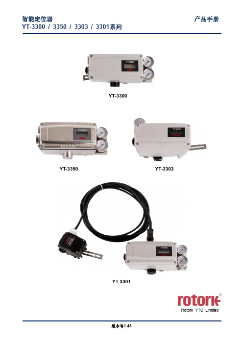
(16)2.5产品规格 (18)YT-3300 / 3303 / 3350规格 (18)YT-3301规格 (19)2.6证书 (21)2.7部件和组件 (23)YT-3300 / 3350 (23)YT-3303 (24)YT-3301 (25)2.8产品尺寸 (26)YT-3300 (26)YT-3350 (27)YT-3303 (28)YT-3301 (29)3安装 (30)3.1安全 (30)3.2安装工具 (30)3.3直行程定位器安装 (31)标准反馈杆型直行程定位器安装 (31)YT-3300L / 3350L适配器杆型的安装(无导管执行器) (37)3.4角行程定位器安装 (40)YT-3300R / 3350R组件 (40)YT-3303R组件 (41)YT-3301R远程传感器组件 (41)角行程支架信息(仅YT-3300R / 3350R / 3303R) (42)角行程定位器安装步骤 (43)4连接- 空气 (45)4.1安全 (45)4.2供给压力条件 (45)4.3管路连接 (45)4.4连接- 执行器管路 (46)单作用执行器 (46)双作用执行器 (47)5连接- 电源 (48)5.1安全 (48)5.2连接 (49)5.3接地 (51)6调节 (52)6.1限位开关调节 (52)6.2A/M开关调节 (53)6.3孔口件安装 (54)板型孔口件安装(YT-3303除外) (54)可变孔口件调节(仅YT-3303) (54)7选配型副PCB安装 (55)7.1安装步骤 (55)8维护 (57)8.1供给压力 (57)8.2密封件 (57)9自动校准和PCB操作 (58)9.1警告 (58)9.2按钮说明 (58)9.3运行模式(RUN) (58)9.4自动校准模式(AUTO CAL) (59)AUTO1校准(AUTO1) (59)AUTO2校准(AUTO2) (60)AUTO 3校准(AUTO 3) (60)AUTO HF校准(AUTO HF) (60)9.5手动模式(MANUAL) (61)9.6参数模式(PARAM) (61)死区(dEAdZONE,%) (62)P数值(KP) (62)I数值(KI) (62)D数值(Kd) (63)P_ (KP_),I_(KI_),D_ (Kd_)数值 (63)KF Up数值(KFUP) (63)KF Down数值(KFdN) (63)控制模式(CTRL) (64)9.7手动校准模式(HAND CAL) (65)阀门零点(PV ZERO)和终点(PV END) (65)发送器零点(TR ZERO)和终点(TR END) (66)正向/反向反馈信号(TR NORM / REVS) (67)正向/反向HART信号(HT NORM / REVS) (67)9.8阀门模式(VALVE) (68)作用调节(ACT RA / dA) (68)阀门流量特性调节(CHAR) (69)用户定义流量特性(USER SET) (70)用力打开(TSHUT OP) (71)用力关闭(TSHUT CL) (72)分程模式(SPLIT) (72)分程自定义零点设置模式(CST ZERO) (73)分程自定义终点设置模式(CST ENd) (73)内插模式(ITP ON / OFF,ITP USER SET) (74)作用类型(SINGLE / dOUBLE) (74)杆型(STd / AdT) (74)9.9诊断(dIAGNO) (75)PST简介 (75)PST模式(PST) (76)PST Configuration (PST CFG) (77)PST Result (PST RSLT) (80)9.10查看模式(VIEW) (81)10错误和警告代码 (83)10.1在自动校准期间显示的错误代码 (83)10.2使用产品时显示的错误代码 (84)10.3可在“查看模式”下检查的错误代码 (84)10.4可在“查看模式”下检查的警告代码 (85)11主要软件地图 (86)1 引言1.1 一般用户信息感谢您购买Rotork YTC Limited产品。
UDC3300操作手册(中文)

Honeyw ellUDC3300过程控制器中文操作手册Measur ement & Contro l北京办公室联系人:***电话:010-84583280-246传真:010-84583103手机:13801361132目录1、面板显示屏说明 (3)2、键盘功能介绍 (4)3、组态子菜单 (5)3.1 LOOP1TUNING ------ 回路1参数整定 (5)3.2 LOOP2TUNING ------ 回路2参数整定......................... ..................63.3SP RAMP, SP Rate or SP Programming ------设定点斜坡/设定点程序............................ .. (7)3.4 Accutu ne ------自适应调整设定............................................ . (9)3.5 ALGORI THM ------控制算法设定................................ (9)3.6 OUTPUT ALGORI THM ------ 输出算法.................................... . (14)3.7 INPUT1 ------ 输入1 .......................………………......................143.8 INPUT2 ------ 输入2 ...................................................................163.9 INPUT3 ------ 输入3 ...................................................................183.10 LOOP1CONTRO L ------ 回路1控制................................................203.11 LOOP2CONTRO L ------ 回路2控制................................................213.12 OPTION ------ 选项 (23)3.13 COMMUN ICATI ONS------ 通讯....................................... .. (25)3.14 ALARMSET ------ 报警设定 (26)1、面板显示屏说明2、键盘功能介绍3、组态子菜单详解3.1 LOOP1TUNING ------ 回路1参数整定3.2 LOOP2TUNING ------ 回路2参数整定3.3 SP RAMP,SP Rate or SP Programming ------ 设定点斜坡/设定点程序3.4 Accutu ne ------自适应调整设定3.5 ALGORI THM ------控制算法设定3.6 OUTPUT ALGORI THM ------ 输出算法3.7 INPUT1------ 输入13.8 INPUT2------ 输入23.9 INPUT3------ 输入33.10 LOOP1CONTRO L ------ 回路1控制3.11 LOOP2CONTRO L ------ 回路2控制3.12 OPTION ------ 选项3.13 COMMUN ICATI ONS------ 通讯3.14ALARMSET ------ 报警设定3.15 DISPLA Y ------ 显示设定3.16 CALIB------ 标定现场可重新标定输入、输出,详见产品手册第七章。
Sun Fast 3300 说明书
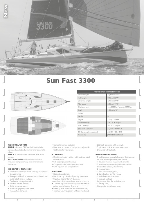
weNSun Fast 3300SALOON• T able with folding leaves,• 2 bench seats with backrest 1,95 m / 6’5" long,• S torage under bench seats and behind backrests,• 1 opening deck hatch,• C ushions and backrests have removable covers – Sunbrella ®,• Removable floorboards,• 100 L / 26 US gal water tank under saloon seating.GALLEY• Large galley to port,• Storage with countertop,• Storage and access to through-hull,• Stainless steel sink,• Pressurised cold water tap,• Storage for flatware,• 2 burners rotating hob,• 40 L / 11 US gal icebox,• H igh surrounding fiddle with stainless steel handrail,• Ergonomic moulded seat,• L arge fixed plexiglas ® window on coachroof, allowing forward and upwards view.AFT CABINS • D ouble berth 2,00 m / 6’7" long, one berth can be lifted for sleeping while heeling,• Mattresses with removable fabric covers,• 1 port opening into the cockpit per cabin,• 1 fabric hanging locker in each cabin,• Storage space underneath the berths,• Complete access to engine compartment,• Access to battery switches,• F abric cabin doors,• Fuel gauge.HEAD COMPARTMENT • Finished in GRP ,• L ightweight GRP sink with pressurised water tap,• 1 opening deck hatch with vent,• 1 marine head with manual pump,• 80 L / 21 US gal holding tank, with crusher and flush valve.FORWARD SECTION • C omposite bulkhead with through access via a watertight PVC hatch.ENGINE • D iesel engine Yanmar 2YM15 - 15 HP ,• E ngine throttle in the cockpit with removable handle,• Engine panel in the cockpit,• Sound insulation for engine compartment,• Access via removable companionway,• Shaft line transmission,• 125A alternator,• 2-blade folding propeller Flex-o-Fold,• Fuel filter,• Raw water filter,• Anti-siphon gooseneck,• 50 L / 13 US gal roto-moulded fuel tank.MISCELLANEOUS • S traight keel, mixed lead / iron with an epoxy surface treatment,• Owner’s manual,• 2 winch handles,• All through-hulls are flush-mounted,• Bilge pump.HEADROOM• Companionway: .....................1,78 m / 5’10" • Forward end of saloon: .........1,54 m / 5’1" • Aft cabins: .....................................1,88 m / 6’2"MAIN OPTIONS • R unning rigging for symmetrical spinnaker and carbon spinnaker pole, • R unning rigging for asymmetric spinnaker and long, composite bowsprit,• Removable drum genoa furler - Harken,• Headstay foil - Harken,• Harken Performa winches,• Carbon-fibre mast,• Carbon-fibre boom,• Water ballasts 2 x 200 L / 2 x 53 US gal,• S horepower, 25 Ah battery charger and 1 additional 140 Ah AGM EXIDE battery,• L ithium batteries in replacement of the complete service battery pack,• Lee cloth kit in the saloon,• Raymarine / T acktick electronics package,• 2 instrument repeaters mounted on mast,• R aymarine GPS at the chart table with Wifi router,• Raymarine autopilot,• Hydraulic LS40 autopilot linear drive,• Halyard bags in the cockpit,• 12V Fridge,• 2-bladed folding Gori racing propeller.10 20 30 40 50607080901001101201301401501601702468101214164 6 81012142466810121620253068101216202530Polar plots and data can be viewed at :JEANNEAU - 32 avenue des Sables - CS 30529 - 85505 Les Herbiers Cédex FRANCE - Tél. (33) 2 51 64 20 20Sun Fast 3300DECK HARDWARE• Forward stainless steel pulpit,• C omposite bowsprit with fitting for mounting a gennaker furler or asymmetric spinnaker,• Aft stainless steel pushpits,• 2 levels of lifelines on stainless steel stanchions with stiffeners,• 2 mooring cleats aft (on deck edge),• 2 mooring cleats forward (on deck edge),• Anchor locker,• T oerail moulded with the deck, specially shaped for crew hiking,• Mainsail traveller track on cockpit floor,• Harken deck hardware,• S pinlock line jammers on coachroof for halyards and control lines,• 2 Harken 40.2 primary winches for genoa, spinnaker and backstays,• 2 Harken 40.2 winches on coachroof for halyards and control lines,• 2 Guiding fairleads for genoa sheets,• 2 Guiding fairleads for adjustable backstays,• 2 Transversal tracks for genoa lead cars on sidedecks,• Chainplates for shrouds on hull sides,• Chainplates for backstays,• Fully equipped mast step with halyards blocks,• Stainless steel handrails on PANIONWAY • 3 steps with non-slip strips,• L ightweight entrance door lockable from inte-rior and exterior with air vents,• Sliding GRP hatch,• Ocean cover in GRP ,• R emovable composite companionway for easy access to the engine,• S tainless steel handrails on each side of com-panionway.ELECTRICAL PANEL• E lectrical panel for “Offshore” use,• USB plug,• Voltmeter for engine battery bank,• Voltmeter for house battery bank,• 1 engine battery 50 Ah EXIDE and 1 service battery 140 Ah AGM EXIDE.CHART TABLE • L arge chart table to starboard with storage, desk compatible with laptop tablet and marine computers,• Panel for electronics, with easy access to cabling,• H igh surrounding fiddle with stainless steel handrail,• Ergonomic moulded seat,• L arge fixed plexiglas ® window on coachroof, allowing forward and upwards view.Provisional specifications are non-contractual and can be changed or modified withour notice.© J.M. Liot - September 2019。
QJZ-1600/3300-8说明书

1.3.7无滴水及其它液体浸入的地方。
1.3.8安装类别为Ⅲ类。
1.4 型号组成及其代表意义
Q J Z-□ / □ -□
回路数
额定电压(V)
额定总电流(A)
真空
隔爆兼本质安全型
磁力起动器
1.5 产品执行标准
1.5.1 本系列产品符合MT111-1998《矿用隔爆型低压交流真空电磁起动器》。
五、产品使用、操作方法.....................................................................4
六、参数设定及调试.........................................................................5
十七、远控接线示意图......................................................................13
十八、电气原理图..........................................................................13
1.2 主要用途及适用范围
本系列组合开关适用于煤矿井下及其周围介质中有甲烷、煤尘等爆炸性混合物气体的环境中,在交流50Hz,额定电压至3300V,额定总电流至1600A及以下的线路中,符合GB3836.1~3和GB/T14048.4-2003、MT111-1998标准要求,组合开关作为采区及及其它工作面各种设备的启动开关,当设备出现过载、短路、过压、欠压等故障时能自动切断电源并显示故障信号,组合开关在合闸前具有漏电闭锁及试验功能,运行时能显示各支路电流值及电压值;具有欠压、过载、缺相、短路及漏电闭锁等保护。组合开关对所控电机可以实现单台控制、单机双速、双机双速控制,并在停机时通过隔离开关改变电机的相序。 对采煤机、刮板运输机、胶带输送机主电机、油泵电机、冷却风扇电机及胶带张紧电机、卷带电机、破碎机、转载机等电机进行起动、停止控制,并能对电动机及供电线路进行保护,达到采区或其它工作面供电设备自动化控制的目的。
YDC3300用户手册

2.主要特征 ................................................................................................................................... 3
2.1 2.2 概述 ...................................................................................................................................................... 3 功能和特点 .......................................................................................................................................... 3
3.安装 ............................................................................................................. 4
3.1 3.2 3.3 3.4 3.5 3.6 3.7 3.8 3.9 3.10 初步检查 .............................................................................................................................................. 4 产品外观图 .......................................................................................................................................... 4 LCD 面板 ............................................................................................................................................ 6 安装须知 .............................................................................................................................................. 6 外部保护装置 ...................................................................................................................................... 7 电源线 .................................................................................................................................................. 7 电源线连接 .......................................................................................................................................... 8 UPS 电池连接 ..................................................................................................................................... 9 并机系统 UPS 的装配 ...................................................................................................................... 10 连接计算机 .........................................................................................................................................11
3300XL8中文

BN 部 件 号 141194-01 版本 F,2003 年 3 月
技术说明和订货信息
Page 1 of 28
3300 XL 的 SpringLoc 端子带不需要特殊的 安装工具即可紧固。由于不需要螺丝紧固, 不会发生松动,所以连线更坚固。
趋近式探头和延伸电缆
3300 探头和延伸电缆与以前相比也有很大提 高。 TipLoc™专利模具技术保证了探头端部 和主体之间的牢固连接。探头电缆使用 CableLoc™专利设计安全地连接到探头端 部,能承受 330 牛(75 磅)的拉力。
0 到 10kHz:典型值为+0 到-3dB,305 米(1000 英尺)现场联线。
最小靶面尺寸:直径 15.2mm(0.6inch) (平
面靶面)
轴直径:
最小:
50.8mm (2in)
推荐最小:
76.2mm (3in)
当对直径小于 50mm(2in) 的轴进行测 量时,通常 要求径向振动或轴向位移 传感器间距很近,这将导 致因传感器的电磁场相互 干扰而发生读数错误。应
当前置器和延伸电缆温度
范围在-35°C 至+65°C (-31°F 至+149°F)、 探头温度范围在 0°C 至 +45°C(+32°F 至+113° F)时, ISF 保 持在
7.87V/mm(200mV/mil)±1 8%之内, DSL 保 持在
±0.152mm(±6mils)之 内。
大温度范围系统的性能:
技术规格
在没有另外注明时,以下关于 3300 XL8 mm 前置器、延伸电缆和探头的技术规格是在下 列条件下得到的:温度+18°C~+27°C (+64°F~+80°F°),-24Vdc 电源供电, 10KΩ负载,AISI4140 钢被测靶面,探头间隙 为 1.27mm (50mils)。 技术特性适用于完全 由 3300 XL 8mm 部件组成的系统。其精度和 可互换性指标不适用于未经本特利内华达 AISI 4140 钢靶面校准的传感器系统。
3300多回路组合开关使用说明手册

电气原理说明一.模块部分原理1.分、合闸接触器CJ合闸过程如下:在没有故障及异常情况下,保护器保护接点K2-K2K闭合,按下启动按钮或保护器程序合闸点(K3-K3K)动作,本安插件动作,本安插件输出点导通,功率继电器J吸合,J 吸合后KA继电器线圈接通控制电压,KA吸合控制真空接触器CJ 吸合,CJ常开辅助接点接通,保持本安插件控制点处于一直导通状态,CJ接触器一直处于吸合状态。
接触器分闸分两种方式,通过按钮或保护器动作分闸,其原理相同。
按下停止按钮或保护器保护点K2-K2K动作打开,本安回路断开,本安插件输出点断开,控制功率继电器J分断,KA分断,接触器CJ分断。
2.漏电检测部分对于漏电检测回路,模块上电后,高压真空继电器ZK控制线圈导通,常开点闭合,保护器漏电检测部分投入到主回路中。
模块合闸时,J功率继电器动作常闭点打开ZK线圈释放,并且在CJ吸合前漏电检测回路已从主回路中退出。
模块分闸时,为了保证操作过电压不会影响控制部分正常工作,通过KA继电器断电延时触点控制ZK在接触器分闸10秒后吸合,使漏电检测回路延时投入工作。
3.模块换向控制部分模块换向是通过保护器换向控制点K1-K1K闭合下发命令。
当下发换向命令后,K1-K1K闭合控制S1继电器吸合,S1常开点闭合当换向盘处于正向位置时,XK2动作,S2继电器吸合状态,ZJ1继电器控制线圈回路没有导通,因此ZJ2继电器吸合自保并互锁ZJ1继电器回路,控制电机旋转,当到达XK1位置时,XK1动作,换向完成。
处于反向位置时换向过程也相同。
通过电气互锁,当处于换向过程时(ZJ1或ZJ2吸合状态),接触器不吸合,同样,当接触器吸合时,换向操作同样无效。
4.模块保护器部分外部接口:AC1、AC2为保护器供电电源;IA、IB、IC、IN为电流互感器接点URW与GND为漏电检测回路接点;24V与XJ0~XJ4为反馈信号检测点,其中XJ0为接触器分、合反馈点,XJ2为正、反向反馈点,XJ3为换向到位反馈点;K1-K1K为换向控制常开点,发出换向命令后闭合时间为1SK2-K2K为故障及程序控制常开保护接点,上电自检无故障后闭合,当存在故障及进行逻辑控制及需要分断接触器时也通过该点控制;K3-K3K为程序合闸点,逻辑控制及本机控制时通过该点控制接触器吸合;485+、485-为标准RS485通讯接点,与多组合控制单元通讯。
Manitowoc 3300 Series 产品指南说明书

features •4models …3330F:8.5T (7.7mt) 3-section boom with25 ft. 2 in. (7.6m) Tip Height3330FL:8.5T (7.7mt) 3-section boom with33 ft. 6 in. (10.2m) Tip Height3339: 9.0T (8.1mt) 3-section boom with 38ft. 2 in. (11.6m) Tip Height3340B: 10.5T(9.5mt) 3-section boom with 38ft. 2 in. (11.6m)Tip Height •6ft. (1.8m)fixedextension (3330F / FL)and 12 ft. (3.6m)offsettable swingaway extension (3339 & 3340B)•70 bhp (52.2 kW) GM EFI dual fuel engine or 99 bhp (73.8 kW) Cummins diesel engine3300SeriesIndustrial Hydraulic Cranecontents235678910111213141516*Product may be shown with optional equipment.features2Standard:21 ft. (6.4m) main boom on the 3330F30 ft. (9.1m) main boom on the 3330FL32ft. 10 in. (10.0m) main boom on the 3339 &3340BOptional:Manual 4th main boom section adds 10 ft. (3.0m) additional main boom length on 3330F and3330FL only.Standard:4-wheel coordinated steer Optional:2-wheel, 4-wheel, and crab steer(std. on 3339)Standard:2-wheel, 4-wheel, and crab steer with self alignment (3340B)Standard:Open air cab shell w/overhead safety glassOptional:Closed cab with hinged door, heater, and defrosterStandard:Cummins QSB 3.3L turbo-charged diesel rated @ 99bhp (73.8kW) @ 2600 rpm.•Single position oblique style outriggers •Narrow width for inside aisle wayusage33300S e r i e sspecificationsaudible warning to the crane operator and disengages all crane functions whose movement can cause two-blocking.in conjunction with the anti-two block system to assist the operator in efficient operation of the unit within the limits of the load chart. The display panel displays the hook load and warns the operator when a preset load capacity is exceeded. Thewarning is an audible alarm. In conjunction with the load display panel (receiver), there is a wireless transmitter and load sensing pin attached to the boom head that transmits the hook load to the display panel.but stops the telescope out andboom lift down function when a load limit is exceeded. Uses a similar display panel with the addition of displaying boom angle and boom length read outs on the panel.capacity, and allows for operator in-put to set the limits based on load chart. Displays color coded light bar and audible alarm with function cutout if load exceeds entered parameters.Hydraulic driven worm gear and pinion.Maximum speed: 2.05 rpmHydraulic System3330F & 3330FL:(2) gear pumps3339 & 3340B: Variable displacement piston pump and piggyback gear pump.Combined flow:28.5gpm (107.9Lpm)Maximum system operating pressure: 3600 psi3330F & 3330FL: Six section valve bank mounted in dash panel with direct mechanical linkage for low effort lever control.3339 & 3340B: Six section valve bank chassis mounted;operated via dash mounted, pilot pressure hydraulic joysticks.Return line filter with full flow by-pass protection and service indicator.23.5 gallon (89 L) hydraulic reservoir with sight level gauge and steel side plating to guard against side impact damage.speed power up and down.3339 & 3340B: Piston motor drive w/spring applied/hydraulic released brake.Drum Diameter:3330F / FL:9.69 in. (0.24m)3339 & 3340B: 10.63 in. (0.27m)Maximum Single Line Pull:3330F / FL:10,700lb (4 854kg)3339 & 3340B: 14,000lb (6 350 kg)Maximum Single Line Speed:3330F / FL:88 FPM (26.8m / min)3339 & 3340B:120FPM (36.6m / min)Maximum Permissible Single Line Pull:3330F / FL :8,500lb (3 855 kg)(1/2” [12.7mm] Python Ultra XIPS) 3339 & 3340B: 10,000lb (4 536kg)(9/16” [14.0mm] EEIPS)Rope Length :3330F / FL: (3-section boom)97 ft. (29.6m)(4-section boom)130 ft. (39.6m)3339 & 3340B:120 ft. (36.6m)*Denotes optional equipment3300S e r i esfour corners with integral holding valves. Outrigger pads form an integral part of the beam.3340B: Hydraulic telescoping beam with oblique type jack provides extended and down and retracted and down lifting capacities. Integral holding valves on both beam and jack.which operate the beams in pairs from side to side.3340B: Two switch operation mounted on dash panel. One -3-position rocker switch to select all beams / jacks, left beams /jacks only,or right beams / jacks only. Separate -4- way toggle switch to activate beams out / in and jacks down / up. Level bubble indicator located inside operators compartment.*Independent outrigger controls available as an option.(73.8kW) @ 2600 rpm.@2600 rpm.Includes all crane functions, driving controls, and overhead safety glass. Other standard equipment include a durable weather resistant seat with seat belt, hourmeter, sight levelbubble, and fire extinguisher. The dash panel includes engine oil pressure gauge, engine water temperature gauge, fuelgauge, transmission low oil and high temperature warning lights,low battery warning light, and brake system low pressurewarning light. The LSI (load indicator) receiver is mounted to the top of the dash and provides warning for A2B and exceeded load capacity.rear glass. Hinged full door with sliding glass.Front windshield wiper and heater and defroster is included.guard against side impact.Electrical SystemOne 12V maintenance free battery, 820CCA @ 0°. Jump start connections 63 amp alternator.Front axle drive with planetary hubs and limited slip Differential.2-wheel, 4-wheel steer 3339:2-wheel, 4-wheel w/crab steer 3340B: 2-wheel, 4-wheel, and crab steer w/ electronic selfalignment.Clark synchromesh -4- speeds forward andreverse with stalk mounted forward/reverse selector.3340B:Clark powershift -4- speeds forward and reverse.Stalk mounted shifter on left side of steering column.brakes and limited slip differential.Rear: Fabricated non-drive steer with disc brakesfour wheels. A dash mounted toggle switch activates the dry disc parking brake on the transmission output yoke with a dash warning light.Rear:Rigid mounted to frame3339:57%....no load31%....12,000lb (5 443kg) load 3340B:68%....no load40%....20,000lb (9 072kg) loadG.V.W.3330F:13,400 lb. (6 078 kg)3330FL:15,180 lb (6 885 kg)3339: 15,800 lb (7 167 kg)3340B:16,600 lb (7 530 kg)Miscellaneous Standard EquipmentSingle sheave, “Quick Reeve” style hookblock.;3330F/ FL 8.5T (8.0mt); 3339: 9T (8.1mt); 3340B10.5T (10mt).Back-up alarm.*Denotes optional equipment **TheoreticalEle53300S e r i e sdimensions63300S e r i e sTHIS CHART IS ONL Y A GUIDE AND SHOULD NOT BE USED TO OPERATE THE CRANE.The individual crane’s load chart, operating instructions and other instructional plates must be read and understood prior to operating the crane.3551005101520255151025203030354010505101520253035053330FH E I G H T F R O M G R O U N D I N F E E TOPERATING RADIUS IN FEET FROM AXIS OF ROTA TIONrange diagram73300S e r i e sTHIS CHART IS ONL Y A GUIDE AND SHOULD NOT BE USED TO OPERATE THE CRANE.The individual crane’s load chart, operating instructions and other instructional plates must be read and understood prior to operating the crane.0-17000lbs2-PART 0-8500lbs 1-PART RIGGING CHARTWIRE ROPE: 1/2 inch diameter Min. breaking strength 29750 lbs.REDUCTION CHARTMAIN BOOM FROM RATINGSJIB FROM RATINGS MAIN BLOCK HOOK & BALL JIB, STOWED JIB, DEPLOYED140 lbs 100lbs 0lbs 150 lbs N/A 100lbs N/A 0lbsThe rated loads are the maximum lift capacities as determined by operating radius, boom extension and boom angle. The operating radius is the horizontal distance from a projection of the axis of rotation to thesupporting surface, before loading, tothe center of vertical hoist line or tackle with load applied.The rated loads shown on outriggers do not exceed 85% of actual tipping. The rated loads shown on rubber do not exceed 75% of actual tipping. These ratings are based on freely suspended loads with the crane leveled, standing on a firm, uniform supporting surface. Practical working loads depend on supporting surface, operating radius and other factors affecting stability. Hazardous surroundings, climatic conditions, experience of personnel and proper training must all be taken into account by the operator.The weights of all load handlingdevices such as hooks, hook blocks, slings, etc., except the hoist rope, shall be considered as part of the load. See reduction chart.Ratings on outrigggers are for either outriggers fully extended and down or fully retracted and down. Ratings for outriggers fully retracted and down will apply for any intermediate outrigger setting.Ratings on rubber depend on tirecapacity, condition of tires and proper inflation pressure (100 psi). Loads on rubber may be transported at a maximum speed of 2.5 mph on a smooth hard level surface with boom retracted to the shortest length possible and centered over front.For operating radius not shown, use load rating of next larger radius.The maximum combined total boom and deck load is 12000 lbs. Themaximum deck load only is 14000 bs.Do not induce any external side loads to boom or jib.1)5)6)7)8)2)3)4)*LIMIT RATINGS TO 11,800LBS WHEN 3RD SECTION IS EXTENDED ANY AMOUNT.JIB CAPACITY IS LIMITED BY BOTH STRUCTURAL CAPACITY CHART AND MAIN CAPACITY CHART.SHADED AREAS ARE GOVERNED BY STRUCTURAL STRENGTH, DO NOT RELY ON TIPPING.3330Fload chart83300S e r i e sdimensions3330FL93300S e r i e s3330FL355NO I T C E S 3NO I T C E S 45151025203045°30°60°400°15°55101520253035401005152030253540454545BI J '650510010152025303540451050OPERATING RADIUS IN FEET FROM AXIS OF ROTATIONH E I G H T F R O M G R O U N D I N F E E Trange diagramTHIS CHART IS ONL Y A GUIDE AND SHOULD NOT BE USED TO OPERATE THE CRANE.The individual crane’s load chart, operating instructions andother instructional plates must be read and understood prior to operating the crane.103300S e r i e sload chart0-17000lbs2-P A R T 0-8500lbs 1-P A R T R IGGI N G C H A R TW I R E R O P E :1/2inc h diameter M in. brea k in g stren g t h 29750lbs.R E D UC T I ON C H A R TM A I N B OO M F R O M R A T I N G SJ I B F R O M R A T I N G S M A I N B L O C K H OO K &B A LL J I B ,S T O W E D J I B ,D E P L O Y E D140 lbs 100 lbs 0lbs 150 lbsN /A 100 lbs N /A 0lbs8. Do not induce external side loads to boom or jib.is 14,000 lbs w it h 10:00 x 15tires. T ire in f lation at 12,000 lbs. F or dec k loads onl y ,t h e maximum load 7.T h e maximum combined total boom and dec k load is next lar g er radius.6.F or o p eratin g radius not s h o w n ,use load ratin g o f t h e on a smoot h h ard le v el sur f ace w it h boom retracted ma y be trans p orted at a maximum s p eed o f 2.5m p h tires ,and p ro p er in f lation p ressure (100 p si ).L oads on rubber 5.R atin g s on rubber de p end on tire ca p acit y ,condition o f4.R atin g s on outri gg ers are w it h outri gg ers f ull y extended. be considered as p art o f t h e load. S ee reductrion c h art. h oo k bloc k s ,slin g s ,etc.,exce p t t h e h oist ro p e ,s h all 3.T h e w ei g h ts o f all load h andlin g de v ices ,suc h as h oo k s ,p ro p er h andlin g must all be ta k en into account b y t h e H a z ardous surroundin g s ,ex p erience o f p ersonnel and P ractical w or k in g loads de p end on su pp ortin g sur f ace ,le v eled ,standin g on a f irm ,uni f orm su pp ortin g sur f ace.based on f reel y sus p ended loads w it h t h e mac h ine not exceed 75%o f actual ti pp in g .T h ese ratin g s are o f actual ti pp in g .T h e rated loads s h o w n on rubber do 2.T h e rated loads s h o w n on outri gg ers do not exceed 85%t h e su pp ortin g sur f ace ,be f ore loadin g ,to t h e center distance f rom a p rojection o f t h e axis o f rotation to o f v ertical h oist line or tac k le w it h load a pp lied.o p eratin g radius ,and ot h er f actors a ff ectin g stabilit y .o p erator.to t h e s h ortest len g t h p ossible and centered o v er f ront.at 100 p si.THIS CHART IS ONL Y A GUIDE AND SHOULD NOT BE USED TO OPERATE THE CRANE.The individual crane’s load chart, operating instructions and other instructional plates must be read and understood prior to operating the crane.113300S e r i e s3339THIS CHART IS ONL Y A GUIDE AND SHOULD NOT BE USED TO OPERATE THE CRANE.The individual crane’s load chart, operating instructions and other instructional plates must be read and understood prior to operating the crane.dimensionshorizontal123300S e r i e srange diagram333956545250484644424038363432302826242220181614121086420OPERATING RADIUS IN FEET FROM AXIS OF ROTATION6420246810 1214 16 18 20 22 24 26 28 30 32 34 36 38 40 4244 46 48H E I G H T F R O M G R O U N D I N F E E TTHIS CHART IS ONL Y A GUIDE AND SHOULD NOT BE USED TO OPERATE THE CRANE.The individual crane’s load chart, operating instructions andother instructional plates must be read and understood prior to operating the crane.133300S e r i e sload chart3339THIS CHART IS ONL Y A GUIDE AND SHOULD NOT BE USED TO OPERATE THE CRANE.The individual crane’s load chart, operating instructions andother instructional plates must be read and understood prior to operating the crane.143300S e r i e sdimensionsand the anti-two block bottomed.3340BTHIS CHART IS ONL Y A GUIDE AND SHOULD NOT BE USED TO OPERATE THE CRANE.The individual crane’s load chart, operating instructions and other instructional plates must be read and understood prior to operating the crane.153300S e r i e sTHIS CHART IS ONL Y A GUIDE AND SHOULD NOT BE USED TO OPERATE THE CRANE.The individual crane’s load chart, operating instructions and other instructional plates must be read and understood prior to operating the crane.4262081012141618222426302832463634384042444850525456H E I G H T F R O M G R O U N D I N F E E TOPERATING RADIUS IN FEET FROM AXIS OF ROTATION3340Brange diagram3300S e r i e s16load chartRATING CHARTS AND DISREGARD OF INSTRUCTIONS IS DANGEROUS AND VOIDS WARRANTY.OPERATION OF THIS EQUIPMENT IN EXCESS OFThe rated loads are the maximum lift capacities as determined by operating radius,boom extension and boom angle.The operating radius is the horizontal distance from a projection of the axis of rotation to thesupporting surface,before loading,to the center of vertical hoist line or tackle with load applied.The rated loads shown on outriggers do not exceed 85%of actual tipping.The rated loads shown on rubber do not exceed 75%of actual tipping.These ratings are based on freely suspended loads with the crane leveled,standing on a firm,uniform supporting surface.Practical working loads depend on supporting surface,operating radius and other factors affecting stability.Hazardous surroundings,climatic conditions,experience of personnel and proper training must all be taken into account by the operator.The weights of all load handlingdevices such as hooks,hook blocks,slings,etc.,except the hoist rope,shall be considered as part of the load.See reduction chart.1)Ratings on rubber depend on tirecapacity,condition of tires and proper inflation pressure (100psi).Loads on rubber may be transported at a maximum speed of 2.5mph on a smooth hard level surface with boom retracted to the shortest length possible and centered over front.For operating radius not shown,use load rating of next larger radius.Themaximum combined total boom and deck load is 12000lbs.Themaximum deck load only is 14000bs.Do not induce any external side loads to boom or jib.5)6)7)8)2)3)Ratings on outrigggers are for either outriggers fully extended and down or fully retracted and down.Ratings for outriggers fully retracted and down will apply for any intermediate outrigger setting.4)JIB CAPACITY IS LIMITED BY BOTH STRUCTURAL CAPACITY CHART AND MAIN CAPACITY CHART.SHADED AREAS ARE GOVERNED BY STRUCTURAL STRENGTH,DO NOT RELY ON TIPPING.THIS CHART IS ONL Y A GUIDE AND SHOULD NOT BE USED TO OPERATE THE CRANE.The individual crane’s load chart, operating instructions and other instructional plates must be read and understood prior to operating the crane.3340B173300S e r i esnotes183300S e r i e snotes193300S e r i e snotesConstant improvement and engineering progress make it necessary that we reserve the right to make specification, equipment and price changes without notice. Illustrations shown may include optional equipment and accessories, and may not include all standard equipment.Americas Brazil AlphavilleTel: +55 11 3103 0200Fax: +55 11 4688 2013Mexico MonterreyTel: +52 81 8124 0128Fax: +52 81 8124 0129Europe, Middle East, Africa Algeria HydraTel: +21 3 21 48 1173Fax: +21 3 21 48 1454Czech Republic NetvoriceTel: +420 317 78 9313Fax: +420 317 78 9314France BaudemontTel: +33 385 28 2589Fax: +33 385 28 0430CergyTel: +33 130 31 3150Fax: +33 130 38 6085DecinesTel: +33 472 81 5000Fax: +33 472 81 5010Germany LangenfeldTel: +49 2173 8909-0Fax: +49 2173 8909 30Hungary BudapestTel: +36 13 39 8622Fax: +36 1339 8622ItalyParabiagoTel: +390 331 49 3311Fax: +390 33149 3330Netherlands BredaTel: +31 76 578 3999 Fax: +31 76 578 3978Poland WarsawTel: +48 22 843 3824Fax: +48 22 843 3471Portugal AlfenaTel: +351 229 69 8840Fax: +351 229 69 8848LisbonTel: +351212109 340Fax: +351 212 109 349Russia MoscowTel: +7 495 641 2359Fax: +7 495 641 2358U.A.E.DubaiTel: +97143381861Fax: +971 4 3382 343U. K.MiddlesexTel: +44 1 895 43 0053Fax: +44 1 895 45 9500SunderlandTel: +44 191 522 2000Fax: +44 191 522 2052Asia – Pacific Australia MelbourneTel: +6139336 1300Fax: +61 3 9 336 1322SydneyTel: +61 2 9 896 4433Fax: +61 2 9 896 3122China BeijingTel: +86 10 58674761Fax: +86 10 58674760Xi’anTel: +86 29 87891465Fax: +86 29 87884504Korea SeoulTel: +82 2 3439 0400Fax: +82 2 3439 0405Philippines Makati CityTel: +63 2 844 9437Fax: +63 2 844 4712Factories BrazilAlphavilleChinaZhangjiagangFranceCharlieu La Clayette MoulinsGermanyWilhelmshavenIndiaCalcutta PuneItalyNiella TanaroPortugalBaltar FânzeresSlovakiaSarisU.S.A.ManitowocPort Washington Shady GroveRegional OfficesAmericasManitowoc, Wisconsin, USATel: +1 920 684 6621Fax: +1 920 683 6278Shady Grove, Pennsylvania, USATel: +1 717 597 8121Fax: +1 717 597 4062Europe, Middle East, Africa Ecully, FranceTel: +33 472 18 2020Fax: +33 472 18 2000Asia – Pacific Shanghai, ChinaTel: +86 21 51113579Fax: +86 21 51113578SingaporeTel: +65 6264 1188Fax: +65 6862 4142Regional Headquarters©2008 MANITOWOC Printed in USAForm No. 3300 SeriesPart No. 08-006 / 0208 / 2M。
