光收说明书(机架和台式)
DX-XXXS带宽控制光纤收发器说明书V1.4
一 概述 ................................................................................................................................................................................ 2
六 指示灯状态说明和工作状态设置................................................................................................................................. 5
6.1 指示灯说明................................................................................................................................................................ 5 6.2 工作状态设置............................................................................................................................................................ 6
WR8602JL光接收机说明书(带反向通道)
WR8602JL光接收机说明书WR8602JL是我公司最新推出的高档二输出CA TV网络光接收机,本机前级采用全砷化镓MMIC放大,后级为砷化镓模块放大器,优化的线路设计,加上本公司十多年专业的设计经验,而使本机的达到了较高的性能指标。
单片机控制数码显示各项参数,使工程调试格外方便,是构建CATV网络的主流机型。
一、性能特点■高响应度PIN光电转换管。
■线路优化设计,SMT工艺生产,优化整机信号通道,光电信号传输更流畅。
■专业的射频衰减芯片,射频衰减和均衡线性好,精度高。
■砷化镓放大器件,功率倍增输出,增益高、失真低。
■单片机控制整机工作,数码显示各项参数,操作方便直观,性能稳定。
■优良的AGC特性,输入光功率-9~+2dBm时,输出电平保持不变,CTB、CSO基本不变。
■预留数据通讯接口,可以配接Ⅱ类网管应答器,接入网管系统二、技术参数备注:以上给出的正向射频指标是在末级使用砷化镓25dB功率倍增模块时的参数,如果用户指定使用其他模块时,指标会有所不同。
三、原理框图四、输入光功率与CNR关系表五、功能显示及操作说明Mode: 当前控制模式选择按钮,共七种工作模式▲:为up按钮,在A TT或EQ模式时增加衰减量或均衡量。
▼:为down按钮,在A TT或EQ模式时减少衰减量或均衡量。
以下做详细图示说明:六、构示意图1、光纤引入口2、光纤法兰盘3、输出口1过流插片4、输出口2过流插片5、输出分支或分配器6、射频输出口17、-20dB输出射频检测口8、射频输出口2 9、反向射频衰减器1 10、-20dB反向射频检测口11、反向低通滤波器12、反向射频衰减器2 13、反向射频均衡器14、-20dB反向射频检测口15、反向射频输出口16、主板电源输入插座17、状态显示数码管18、控制模式选择按钮19、参数调节按钮up 20、参数调节按钮down 21、网管应答器数据接口22、反向射频输出/反向光发输出切换插片23、AC60V输入口说明:本机可以配接Ⅱ类网管应答器接入网管系统,网管应答器为本机的选配件,用户可根据实际需要选择是否使用。
14口光纤收发器盒体插拔式机架用户说明书
14口光纤收发器 盒体插拔式机架用户说明书深圳信渝达科技开发有限公司型号:XTR-0201014一、 内容简介本手册描述了14槽机架的使用方法,功能特点、操作指南。
希望用户在使用此机架之前,仔细阅读本手册,并按照使用步骤仔细安装使用,以免对机器造成不必要的伤害。
二、 核对清单在您开始使用14槽机架之前,请对照装箱清单进行清点。
— 14槽光纤收发器机架— 电源线(220VAC供电用)或电源线接头(-48VDC供电用)— 固定收发器在机架上的组件14个、旋钮6颗、前面小挡板一块 — 用户手册一本三、 系统概述14槽机架是一个高集成度的设备集成中心,可将多个快速以太网光纤收发器集成在机架上,使用更加方便。
外置电源收发器除了可以单机工作外,借助14槽机架也可以集中上架使用,便于管理和供电。
此机架最多可安装14个快速以太网收发器。
支持热插拔,具有后备电源,能为网络系统提高可靠、高效经济的解决方案。
四、 安装方法1. 对单电源而言:将二端三芯电源线的一端插在开关电源的220V处,此二端三芯电源线的另一端则插到220V的交流供电插孔处(-48VDC则接在-48VDC的支流电源上)。
工作时,将开关电源上的开关ON/OFF拨至ON处,此时电源指示灯呈绿色。
机架两侧风扇开始转动。
2. 如果是双电源同时工作。
则同时打开开关电源上的电源开关,将两个开关电源的开关均拨到ON/OFF的ON处。
此时,开关电源上的指示灯亮(绿色),机架即开始工作。
同时机架两侧风扇开始转动。
3. 开关电源断开电,取下机架上的前面板,把要使用的光纤收发器插入机架上,按上述步骤2,打开开关电源,此时,光纤收发器的POWER灯亮(绿色),然后按照光纤收发器的使用方法操作即可。
五、 规格说明性能1. 十四槽标准十九英寸2U机箱,可安装在机房机架中,便于统一管理和维护;2. 采用无源背板总线结构,可提供稳定的电源输入;3. 支持每台收发器的热插拔操作;4. 电源进行了充分屏蔽,防止了电源产生的电磁信号干扰模块组的正常运行;5. 选用开关电源,能够持续稳定的长时间工作,同时提供过压、过流保护,电源输出纹波小于20mV;6. 机架为局端的以太网光纤收发器提供最大限度的可靠性保证;电源要求:输入:交流工作电压 85-265VAC/50Hz 输出:直流工作电压 +5VAC纹波:≤20mv噪声:≤50mv环境要求工作温度范围 0-50℃储存温度范围 -20-65℃相对湿度 5%-65无凝结尺寸:435×230×90mm(长×宽×高) 19英寸2U高。
以太网光纤收发器 以太网光纤收发器机架 说明书
以太网光纤收发器 以太网光纤收发器机架 说明书(使用前先阅本说明书) 简介:感谢您购买千兆光纤收发器!该千兆光纤收发器支持IEEE802.3Z/AB 1000Base-SX/LX协议,支持全双工或半双工工作模式,自适应直通线与交叉线功能。
本手册适用于1000 Base-T 自适应各型号的光纤收发器,请用户购买时按需要参照以下订购指南选购。
光纤收发器订购指南:型号 规格说明NT-2100 1000M,多模500米NT-2100S-10 1000M,单模0-10公里NT-2100S-20 1000M,单模0-20公里NT-2100S-50 1000M,单模0-50公里NT-2100S-80 1000M,单模0-80公里NT-2100F 卡式铝合金外壳1000M,多模500米NT-2100F-10 卡式铝合金外壳1000M,单模0-10公里NT-2100F-20 卡式铝合金外壳1000M,单模0-20公里NT-2100F-50 卡式铝合金外壳1000M,单模0-50公里NT-2100F-80 卡式铝合金外壳1000M,单模0-80公里NT-2100P 卡式1000M,多模500米NT-2100P-10 卡式1000M,单模0-10公里NT-2100P-20 卡式1000M,单模0-20公里NT-2100P-50 卡式1000M,单模0-50公里NT-2100P-80 卡式1000M,单模0-80公里NT-S2100-10 单纤双向1000M,单模0-10公里NT-S2100-20 单纤双向1000M,单模0-20公里NT-S2100-40 单纤双向1000M,单模0-40公里NT-S2100P10 卡式单纤双向1000M,单模0-10公里NT-S2100P20 卡式单纤双向1000M,单模0-20公里NT-S2100P50 卡式单纤双向1000M,单模0-50公里包装清单在安装收发器前,请确认包装内是否有以下物品。
MAX3969 光电接收器限幅器说明书
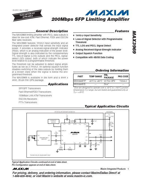
General DescriptionThe MAX3969 limiting amplifier with PECL data outputs is ideal for low-cost ATM, Fast Ethernet, FDDI and ESCON fiber optic receivers.The MAX3969 features 1mV P-P input sensitivity and an integrated power detector that senses the input signal power. It provides a received-signal-strength indicator (RSSI), which is an analog indication of the power level.Signal strength is also indicated by the complementary TTL loss-of-signal (LOS) outputs and the PECL signal-detect (SD) output, both of which indicate the power level relative to a programmable threshold.The threshold can be adjusted to detect signal ampli-tudes as low as 2.7mV P-P . An optional squelch function disables switching of the data outputs by holding them at a known state when the signal is below the pro-grammed threshold.The MAX3969 is available in die form and a 4mm x 4mm, 20-pin thin QFN package.ApplicationsSFP/SFF TransceiversFast Ethernet/FDDI Transceivers 155Mbps LAN ATM Transceivers ESCON Receivers FTTx TransceiversFeatures♦1mV P-P Input Sensitivity♦Loss-of-Signal Detector with Programmable Threshold ♦TTL LOS and PECL Signal Detect♦Analog Received-Signal-Strength Indicator ♦Output Squelch Function♦Compatible with 4B/5B Data CodingMAX3969200Mbps SFP Limiting Amplifier________________________________________________________________Maxim Integrated Products1Ordering InformationTypical Application CircuitsFor pricing, delivery, and ordering information,please contact Maxim/Dallas Direct!at 1-888-629-4642, or visit Maxim’s website at .temperature (T J ) range, but are tested and guaranteed only at T A = +25°C.Typical Application Circuits continued at end of data sheet.Pin Configuration appears at end of data sheet.M A X 3969200Mbps SFP Limiting Amplifier 2_______________________________________________________________________________________ABSOLUTE MAXIMUM RATINGSStresses beyond those listed under “Absolute Maximum Ratings” may cause permanent damage to the device. These are stress ratings only, and functional operation of the device at these or any other conditions beyond those indicated in the operational sections of the specifications is not implied. Exposure to absolute maximum rating conditions for extended periods may affect device reliability.Power-Supply Voltage Range (V CC , V CCO )..........-0.5V to +7.0V Voltage at FILTER, RSSI, IN+, IN-, CZP, CZN, SQUELCH,INV, V TH ..................................................-0.5V to (V CC + 0.5V)TTL Output Current (LOS, LOS ).........................................±9mA PECL Output Current (OUT+, OUT-, SD).........................±50mA Differential Voltage Between CZP and CZN..........-1.5V to +1.5V Differential Voltage Between IN+ and IN-.............-1.5V to +1.5VContinuous Power Dissipation (T A = +85°C)20-Pin Thin QFN (derate 16.9mW/°C above +85°C)....1099mW Operating Junction Temperature Range (die).....-40°C to +150°C Die Attach Temperature...................................................+400°C Storage Temperature Range.............................-50°C to +150°C Lead Temperature (soldering, 10s).................................+300°CELECTRICAL CHARACTERISTICS(V CC = +2.97V to +5.5V, PECL outputs terminated with 50Ωto V CC - 2V, R1 = 100k Ω, T A = -40°C to +85°C, unless otherwise noted.Typical values are at V CC = +3.3V, T A = +25°C.) (Note 1)LOS-DEASSERT LOS-ASSERT Note 3:Relative to supply voltage (V CCO ).Note 4:AC characteristics are guaranteed by design and characterization.Note 5:Input < LOS threshold (LOS = HIGH), V LOS = 2.4V.Note 6:Pulse-width distortion = [(width of wider pulse) - (width of narrower pulse)] / 2, measured with 100Mbps 1-0 pattern.MAX3969200Mbps SFP Limiting Amplifier_______________________________________________________________________________________3Typical Operating Characteristics(V CC = +3.3V, PECL outputs terminated with 50Ωto V CC - 2V, R1 = 100k Ω, T A = +25°C, unless otherwise noted.)SUPPLY CURRENT vs. TEMPERATURE(PECL OUTPUTS OPEN)AMBIENT TEMPERATURE (°C)S U P P L Y C U R R E N T (m A )603510-15510152025303540455055600-40851ns/divOUTPUT EYE DIAGRAM(V IN = 2mV P-P , 155Mbps, 223 - 1 PRBS)200mV/div MAX3969 toc021ns/divOUTPUT EYE DIAGRAM(V IN = 1500mV P-P , 155Mbps, 223 - 1 PRBS)200mV/divMAX3969 toc03TRANSFER FUNCTIONM A X 3969 t o c 04DIFFERENTIAL INPUT VOLTAGE (mV P-P )D I F FE R E N T I A L O U T P U T V O L T A G E (m V P -P )10001001010.1800100012001400160018006000.0110,000BIT ERROR RATIO vs. DIFFERENTIALINPUT VOLTAGEDIFFERENTIAL INPUT VOLTAGE (mV P-P )B I T E R R O R R A T I O0.410-03010-0410-0510-0610-0710-0810-0910-1010-1110-120.10.20.30.50.60.70.8RSSI VOLTAGE vs. DIFFERENTIALINPUT VOLTAGEDIFFERENTIAL INPUT VOLTAGE (mV P-P )V R S S I (V )100101.201.401.601.802.002.202.402.602.803.001.00110001.41.61.51.91.81.72.22.12.02.3-4020-20406080100RSSI VOLTAGE vs. TEMPERATURE (LOS LOW, RSSI LOAD > 10k Ω)AMBIENT TEMPERATURE (°C)V R S S I (V )POWER-DETECT THRESHOLD vs. R2(R1 = 100k Ω)R2 (k Ω)D I F FE R E N T I A L I N P U T V O L T A G E (m V P -P )1101009080706050403020101001000110120032145678910-4010-15356085LOSS-OF-SIGNAL HYSTERESISvs. TEMPERATUREAMBIENT TEMPERATURE (°C)20l o g (V D E A S S E R T / V A S S E R T ) (d B )M A X 3969200Mbps SFP Limiting Amplifier10μs/div POWER-DETECT TIMING WITH SQUELCH (INPUT = 12mV P-P , C FILTER = 0.01μF,R2 = 15k Ω, 155Mbps, 223 - 1 PRBS)INMAX3969 toc10OUTLOSSDPULSE-WIDTH DISTORTION vs. DIFFERENTIAL INPUT VOLTAGEDIFFERENTIAL INPUT VOLTAGE (mV P-P )P U L S E -W I D T H D I S T O R T I O N (p s )1000100101020304050607080901000110,00000.20.40.60.81.01.21.41.6-40-1510356085DATA OUTPUT TRANSITION TIMEvs. TEMPERATUREM A X 3969 t o c 12AMBIENT TEMPERATURE (°C)T R A N S I T I O N T I M E (n s )Typical Operating Characteristics (continued)(V CC = +3.3V, PECL outputs terminated with 50Ωto V CC - 2V, R1 = 100k Ω, T A = +25°C, unless otherwise noted.)MAX3969200Mbps SFP Limiting Amplifier_______________________________________________________________________________________5Pin DescriptionFigure 1. Functional DiagramDetailed DescriptionThe MAX3969 contains a series of limiting amplifiers and power detectors, offset correction, data-squelch circuitry, TTL buffers for LOS outputs, and PECL output buffers for signal detect (SD) and data outputs. See Figure 1 for the functional diagram.Gain Stages and Offset CorrectionA cascade of limiting amplifiers provides approximately 65dB of combined small-signal gain. The large gain makes the amplifier susceptible to small DC offsets in the signal path. To correct DC offsets, the amplifier has an internal feedback loop that acts as a DC autozerocircuit. By correcting the DC offsets, the limiting amplifi-er sensitivity and power-detector accuracy are improved.The offset correction is optimized for data streams with a 50% duty cycle. A different average duty cycle results in increased pulse-width distortion and loss of sensitivi-ty. The offset-correction circuitry is less sensitive to vari-ations of input duty cycle (for example, the 40% to 60%duty cycle encountered in 4B/5B coding) when the input is less than 30mV P-P .The data inputs must be AC-coupled for the offset cor-rection loop to function properly. Differential input impedance is >5k Ω.M A X 3969Power DetectorEach amplifier stage contains a logarithmic FWD, which indicates the RMS input signal power. The FWD outputs are summed together at the FILTER pin where the sig-nal is filtered by an external capacitor (C FILTER ) con-nected between FILTER and V CC . The FILTER signal generates the RSSI output voltage (V RSSI ), which is proportional to the input power in decibels. When LOS is low, V RSSI is approximated by the following equation:V RSSI (V) = 1.2V + 0.5log (V IN )where, V IN is the data input voltage measured in mV P-P .This relation translates to a 25mV increase in V RSSI for every 1dB increase in V IN . The RSSI output is reduced approximately 120mV when LOS is high.Typically the RSSI output is connected to an A/D con-verter for diagnostic monitoring. This output can be left open if not required in the application. The RSSI output is designed to drive a minimum load resistance of 10k Ωto ground, and a maximum capacitance of 10pF. A 10k Ωseries resistor is required to buffer loads greater than 10pF.Signal-Strength ComparatorA comparator is used to indicate the input signal strength relative to a user-programmable threshold.One of the comparator inputs is connected to the RSSI output signal, and the other is connected to the thresh-old voltage (V TH ), which is set externally and provides a trip point for signal-strength indication. When the sig-nal strength is above the threshold, the SD output asserts high and the LOS output deasserts low.Likewise, when the signal strength falls below the threshold, SD deasserts low and LOS asserts high. To ensure chatter-free operation, the comparator is designed with approximately 5dB of hysteresis.SquelchThe squelch function disables the data outputs by forc-ing OUT- low and OUT+ high when the input signal is below the programmed threshold. This function ensures that when there is a loss of signal, the limiting amplifier and all downstream devices do not respond to input noise. Connect SQUELCH to GND or leave it unconnected to disable squelch. Connect SQUELCH to V CC to enable squelch.PECL OutputsThe data outputs (OUT+, OUT-) and signal-detect out-put (SD) are supply-referenced PECL outputs. See Figure 2 for the equivalent output circuit.Both data outputs must be terminated for proper opera-tion, but the SD output can be left open if not required in the application. The proper termination for a PECL output is 50Ωto (V CC - 2V), but other standard termina-tion techniques can be used. For more information on PECL terminations and how to interface with other logic families, refer to Maxim Application Note HFAN-01.0:Introduction to LVDS, PECL, and CML.TTL OutputsThe LOS outputs (LOS, LOS ) are implemented with open-collector, Schottky-clamped, ESD-protected, TTL-compatible outputs. See Figure 3 for the equivalent out-put circuit. The LOS outputs require external pullup resistors for proper operation. Resistor values between 4.7k Ωand 10k Ωare recommended.If the LOS outputs are not required for the application,they can be left open.Design ProcedureProgram the Power-Detect ThresholdThe suggested procedure for setting the power-detect threshold is given below and is illustrated in Figure 4.1)Determine the maximum receiver sensitivity(RX_MAX) in dBm and the PIN-TIA responsivity (G)in V/W.2)Calculate the differential voltage swing (VIN_SEN) atthe MAX3969 inputs while operating at sensitivity.V IN_SEN = 10(RX_MAX / 10)x 2 x G3)Calculate the threshold voltage (V IN_TH ) at whichLOS must be low (SD must be high) by allowing 3.6dB (1.8dB optical) margin for power-detector accuracy.V IN_TH = V IN_SEN x 0.664)Use V IN_TH and the line labeled (SD H IGH / LOSLOW) in the Power-Detect Threshold vs. R2 graph in the Typical O perating Characteristics to deter-mine the value of R2. Select R1=100k Ω.200Mbps SFP Limiting Amplifier 6_______________________________________________________________________________________Select C FILTERFor SFP/SFF, FDDI, 155Mbps ATM LAN, Fast Ethernet,and ESCON receivers, Maxim recommends C FILTER =0.01µF. This capacitor value ensures chatter-free LOS/SD and provides a typical assert/deassert time of 10µs. For other applications, the value of C FILTER can be calculated using the following equation:C FILTER = τ/ 825Ωwhere τis the desired time constant of the power detector.Select C AZ and C INExternal-coupling capacitors (C IN ) are required on the data inputs for the offset correction loop to function properly. The offset correction loop bandwidth is deter-mined by the external capacitor (C AZ ) connected between CZP and CZN. The poles associated with C IN and C AZ must work together to provide a flat response at the lower -3dB corner frequency. For SFP/SFF, FDDI,155Mbps ATM LAN, Fast Ethernet, and ESCON receivers, Maxim recommends the following:C IN = 4700pF C AZ = 1µFMAX3969200Mbps SFP Limiting Amplifier_______________________________________________________________________________________7Figure 2. Equivalent PECL Output CircuitFigure 3. Equivalent TTL Output CircuitFigure 4. Signal Levels for Power-Detect ThresholdM A X 3969Applications InformationWire BondingFor high-current density and reliable operation, the MAX3969 uses gold metalization. For best results, use gold-wire ball-bonding techniques. Use caution if attempting wedge bonding. Die pad size is 4 mils x 4mils. Die thickness is 16 mils.Table 1 lists the bond pad coordinates for the MAX3969.The origin for pad coordinates is defined as the bottom left corner of the bottom left pad. All pad locations are referenced from the origin and indicate the center of the pad where the bond wire should be connected. Refer to Maxim Application Note H FAN-08.0.1: Understanding Bonding-Coordinates and Physical Die Size for detailed information.200Mbps SFP Limiting Amplifier 8_______________________________________________________________________________________Pin ConfigurationChip InformationTRANSISTOR COUNT: 915SUBSTRATE CONNECTED TO GND PROCESS: Silicon Bipolar DIE THICKNESS: 16 milsMAX3969200Mbps SFP Limiting Amplifier_______________________________________________________________________________________9Chip TopographyM A X 3969200Mbps SFP Limiting Amplifier 10______________________________________________________________________________________Typical Application Circuits (continued)MAX3969200Mbps SFP Limiting AmplifierMaxim cannot assume responsibility for use of any circuitry other than circuitry entirely embodied in a Maxim product. No circuit patent licenses are implied. Maxim reserves the right to change the circuitry and specifications without notice at any time.Maxim Integrated Products, 120 San Gabriel Drive, Sunnyvale, CA 94086 408-737-7600 ____________________11©2006 Maxim Integrated Products Printed USAis a registered trademark of Maxim Integrated Products, Inc.Package Information(The package drawing(s) in this data sheet may not reflect the most current specifications. For the latest package outline information, go to /packages.)。
关于光纤收发器的基础知识解析

关于光纤收发器的基础知识解析光纤收发器是网络数据传输中必不可缺少的一种设备,那么什么是光纤收发器呢,光纤收发器的分类是怎样,光纤收发器有怎样的特点,以及光纤收发器的连接方式和发展趋势是怎样的呢?下面就让我们一一来解析光纤收发器的基础知识吧。
光纤收发器光纤收发器,是一种将短距离的双绞线电信号和长距离的光信号进行互换的以太网传输媒体转换单元,在很多地方也被称之为光电转换器(Fiber Converter)。
产品一般应用在以太网电缆无法覆盖、必须使用光纤来延长传输距离的实际网络环境中,且通常定位于宽带城域网的接入层应用;同时在帮助把光纤最后一公里线路连接到城域网和更外层的网络上也发挥了巨大的作用。
一、分类目前国外和国内生产光纤收发器的厂商很多,产品线也极为丰富。
为了保证与其他厂家的网卡、中继器、集线器和交换机等网络设备的完全兼容,光纤收发器产品必须严格符合10Base-T、100Base-TX、100Base-FX、IEEE802.3和IEEE802.3u等以太网标准,除此之外,在EMC防电磁辐射方面应符合FCC Part15.时下由于国内各大运营商正在大力建设小区网、校园网和企业网,因此光纤收发器产品的用量也在不断提高,以更好地满足接入网的建设需要。
1,按光纤性质分类单模光纤收发器:传输距离20公里至120公里多模光纤收发器:传输距离2公里到5公里如5公里光纤收发器的发射功率一般在-20~-14db之间,接收灵敏度为-30db,使用1310nm的波长;而120公里光纤收发器的发射功率多在-5~0dB之间,接收灵敏度为-38dB,使用1550nm的波长。
,2,按所需光纤分类单纤光纤收发器:接收发送的数据在一根光纤上传输双纤光纤收发器:接收发送的数据在一对光纤上传输顾名思义,单纤设备可以节省一半的光纤,即在一根光纤上实现数据的接收和发送,在光纤资源紧张的地方十分适用。
这类产品采用了波分复用的技术,使用的波长多为1310nm 和1550nm.但由于单纤收发器产品没有统一国际标准,因此不同厂商产品在互联互通时可能会存在不兼容的情况。
光纤区别-单模和多模-光端机和光纤收发器的区别-总结贴
光纤区别-单模和多模-光端机和光纤收发器的区别-总结贴按光在光纤中的传输模式可分为:单模光纤和多模光纤um=1微米=0.001毫米多模光纤的纤芯直径为50~62.5μm,包层外直径125μm,单模光纤的纤芯直径为8.3μm,包层外直径125μm。
光纤的工作波长有短波长0.85μm、长波长1.31μm和1.55μm。
光纤损耗一般是随波长加长而减小,0.85μm的损耗为2.5dB/km,1.31μm的损耗为0.35dB/km,1.55μm的损耗为0.20dB/km,这是光纤的最低损耗,波长1.65μm以上的损耗趋向加大。
由于OHˉ的吸收作用,0.90~1.30μm和1.34~1.52μm范围内都有损耗高峰,这两个范围未能充分利用。
80年代起,倾向于多用单模光纤,而且先用长波长1.31μm。
多模光纤多模光纤(Multi Mode Fiber):中心玻璃芯较粗(50或62.5μm),可传多种模式的光。
但其模间色散较大,这就限制了传输数字信号的频率,而且随距离的增加会更加严重。
例如:600MB/KM的光纤在2KM时则只有300MB 的带宽了。
因此,多模光纤传输的距离就比较近,一般只有几公里。
单模光纤单模光纤(Single Mode Fiber):中心玻璃芯很细(芯径一般为9或10μm),只能传一种模式的光。
因此,其模间色散很小,适用于远程通讯,但还存在着材料色散和波导色散,这样单模光纤对光源的谱宽和稳定性有较高的要求,即谱宽要窄,稳定性要好。
后来又发现在1.31μm波长处,单模光纤的材料色散和波导色散一为正、一为负,大小也正好相等。
这就是说在1.31μm波长处,单模光纤的总色散为零。
从光纤的损耗特性来看,1.31μm处正好是光纤的一个低损耗窗口。
这样,1.31μm波长区就成了光纤通信的一个很理想的工作窗口,也是现在实用光纤通信系统的主要工作波段。
1.31μm常规单模光纤的主要参数是由国际电信联盟ITU-T在G652建议中确定的,因此这种光纤又称G652光纤二、单模和多模的技术是同时产生的吗?是不是哪个更先进多模先谈不上那个更先进,一般距离近的用多模,远的只有用单模的,因为多模光纤的收发器比单模的便宜很多三、单模光纤用于长途的传输,多模光纤用于室内数据传输吧长途只能用单模,但是室内数据传输不一定都要用多模四、服务器和存储设备用的光纤是单模还是多模的多半用的是多模,因为偶只是搞通讯光纤对这个问题不是太清楚。
室内光接收机使用使用说明

目录一、光接收机概述 (2)二、特点 (2)三、光接收机方框图 (3)四、面板示意图 (3)五、调试和安装 (3)六、光接收机技术指标 (5)七、故障排除 (6)八、装箱清单 (7)九、型号说明 (7)十、附光纤活动接头清洁维护方法.................................................. .. (8)一、光接收机概述BLR100-RAL系列室内光接收机是珠海柏卫宽带电子有限公司出品的HFC网络的光节点设备。
工作波长兼容1310nm和1550nm,供电方式为高可靠性220V开关电源,采用19"1U高度标准机架外壳。
二、特点1、适用于有线电视及通信行业的图像、语言和数据(压缩数据)信号的远距离光纤传输。
2、采用进口优质高灵敏度PIN光检波器或PHILIPS光电一体化接收模块和PHILIPS射频放大模块(可选砷化镓模块),确保了产品的性能指标和可靠性;3、19"1U高度标准机架外壳,前面板六阶LED接收光功率指示;光功率电平指示灯,从-5dBm、-3dBm、-2dBm、-1dBm、0dBm、+1dBm逐级显示, 方便工程人员及时了解接收光功率的大小;从而方便工程人员进行网络调试;4、1310nm和1550nm双工作窗口,正向带宽47-750MHz、47-862MHz可选。
5、光功率接收范围:-7-+3dBm。
6、内置插件式反向光发射组件接口,可以方便的安装回传光发射模块组件;回传发射模块功率为1mW-3mW,FC/APC和SC/APC两种光接口形式,以备选用;7、前面板加装输出测试口,方便工程人员测试设备输出电平(输出测试口的值相对于射频输出口的值低20dB)。
8、外置可调均衡器及可调衰减器调节,方便使用。
9、输出一路和二路端口可选。
10、各种不同的输出电平规格92dB--102dB(-1dBm光功率接收,3.8%光调制度),客户可以根据输出电平不同向我公司订购相应的产品;三、原理框图BLR100-RAL光接收机原理框图四、面板示意图BLR100-RAL光接收机前面板示意图BLR100-RAL光接收机后面板示意图五、调试和安装(一)安装1、开箱检查请先检查外包装,如发现外包装或设备已经损坏,请保存外包装并通知货运公司,未确认设备完好前,请勿通电。
机架1×16光开关使用说明
>> FSW-1×161U机架1×16光开关使用说明1、产品简介光开关是一种光路控制器件,起着控制光路和转换光路的作用。
在光通信应用中具有重要作用。
光开关主要应用于:光传输系统中的多路光监控、LAN多光源/探测器自动换接以及光传感多点动态监测系统;光测试系统中用于光纤、光器件、网络和野外工程光缆测试;光器件装调。
2、产品特点(1)、具有插入损耗小,切换速度快等特点。
(2)、采用LCD显示屏,非常直观的显示数据,方便用户的操作。
(3)、可设置自动扫描,最大切换间隔时间为99小时59分钟59秒;还可以对扫描的“起始通道”和“结束通道”进行设置。
(4)、可设置“设备地址”,方便用户能在串口资源紧张的情况下,用一个串口控制多台光开关仪器。
(5)、可根据实际情况设置串口通信的波特率,可设的波特率有1200、2400、4800、9600、19200、57600六种。
3出厂设置●设备按键使用权限:允许●初始界面的通道切换:允许●扫描通道为:1 ~ N (N为总通道数)●设备地址:01●串口设置为:9600波特,8位数据位,1位停止位,无奇偶校验。
●IP地址:192.168.0.178 ;工作方式:TCP Server ;工作端口:4001注:用户有特殊要求的除外。
>> FSW-1×164、使用说明4.1 结构示意说明 4.1.1 面板说明前面板(1)、LCD 显示屏:设备地址、当前通道和相关信息的显示。
(2)、RJ45以太网接口、RS-232(或RS-485)串口:设备监控数据信息的通信接口。
(3)、电源指示灯Power1、Power2:工作电源指示。
(4)、▲——上移键;▼——下移键;Enter ——确定键;Esc ——取消键。
(5)、光接口说明:设备面板上的I/O 口为公共端口,1、2、3、……、16分别为各通道号。
4.2、设备连接说明4.2.1 内部光路连接示意说明1×N 光开关内部光路示意图4.2.2 通信接口连接说明 (1)、RS-232接口设备与计算机连接时,应该使用两端都是孔式DB9的串口交叉线。
光纤收发器与光猫

LAN系列光纤收发器
北京银驼铃通信技术有限公司生产的光纤收发器主 要有以下几个系列: 智能型以太网光纤收发器GTT LAN 10/100M 4端口交换式光纤收发器LAN 4-10/100M 流量控制系列光纤收发器 1000M系列光纤收发器 8端口隔离式光纤收发器
LAN系列光纤收发器
4E1 FX光猫
技术指标 2.1、E1接口 速率:2.048Mbps,允许频偏±50ppm 阻抗:75Ω不平衡 HDB3编码:符合ITU-T G.703建议 抖动容限符合G.823标准 输出抖动小于0.05UI 2.2、光接口(双纤) 波 长:1310nm(标准机型)或1550nm 发送功率:≥-12dBm 接收灵敏度:≤-37dBm(BER≤10-11) 接口方式:FC(标准机型)或SC以及单纤 光接口速率为155M
4E1 FX光猫
1、主要特点 提供4个E1接口; 提供1个100M光接口(与光纤收发器对通); 提供双电源(220V与-48V供电); 1.2、 E1接口: E1接口符合ITU-T G.703、G.704和G.823 支持GFP-F 封装格式 支持虚级联(VCAT)及链路容量调整规范(LCAS),符合ITU-T G.7042 标准 支持收发双向E1 序号非对应以及E1 数量不对称应用 支持HDB3 / NRZ 两种码型 支持1-4条E1电路的可用性检测和故障自动处理 E1线路误码率实时监视,并能够根据线路传输性能进行通道保护光接口速率为 155M
1. 智能型以太网光纤收发器 GTT LAN 10/100M
性能特点: ●支持100Base-FX光纤传输标准,可与其他产品互通,10/100Mbps自适应,全双工 /半双工自适应; ●自动协商和连接识别,端口速率绑定; ●支持单纤双向传输模式,为用户节省光纤资源; ●采用1310/1550nm双波长WDM器件设计; ●支持spanning Tree构造容错网络; ●支持超长帧传输,最长可支持2016Byte超长帧; ●传输距离为20-120km; ●提供局端机型,十六槽灵活配置。
光纤收发器光通信产品简单介绍

输媒体转换单位。 ❖ 订购信息示例:10/100M 单模双纤 1310nm 20KM SC接口 外置电源
AC220V (备注:电源类型 包装要求 运输方式)
产品规格对应表
10/100M Auto-sensing fiber media converterv dual fiber (external power supply) 10/100M 自适应,多模,单模双纤,外置电源 5V1A
10/100/1000M single Bi-Di fiber media converter (ExternalPower Supply) 10/100/1000M 自适应,单纤双向-WDM,外置电源 5V2A
10/100/1000M, MM,2km, SC connector,1310/1550nm 多模单纤 10/100/1000M, SM,20km, SC connector, 1310/1550nm 10/100/1000M, SM,40km, SC connector, 1310/1550(FP)nm 35km内 10/100/1000M, SM,40km, SC connector, 1310/1550(DFB)nm 10/100/1000M, SM60km, SC connector, 1310/1550(DFB)nm 10/100/1000M, SM,80km, SC connector, 1490(DFB)/1550(DFB)nm
徐开旺光纤通信产品知识讲座
光纤收发器(Media converter)
一、分类(按结构分): 1.外置光纤收发器 (电源外置) external power supply 2.内置光纤收发器 internal power supply 3.插卡式光纤收发器 Media Converter Card Type 4收发器用户卡 5.机架式光纤收发器 (14槽机架和16槽机架) 14-Slot Media Converter Chassis
光纤收发器机架使用说明

光纤收发器机架使用说明一.产品简介本机架系光纤收发器配套产品,共有三款:14槽机架、16槽插卡式机架和17槽插卡式机架。
14槽机架可将整台外置收发器带铁壳一起插入使用,一台机架最多可插14台收发器,而16槽机架和17槽机架需用配套的卡式收发器插入使用,可分别对应插入16块收发器卡;17槽机架可用于带网管的收发器机架,其中1个插槽用于安装网管卡。
图1 17槽卡式机架面板图本机架用来对多台光纤收发器集中供电,从而减少了连接线,简化了结构;具有工作稳定、适应电源电压范围大、供电容量大、操作方面、便于管理、易于维护等显著优点,适用于要求高可靠性、高容量、高集成度及高性能的工作环境。
本机架支持热插拔,可先用单电源或双电源供电方式,供电电压AC220V或DC48V可选,对机架电源进行维护和更换时不需要拔出光纤收发器,也不需要从机柜中拆下本机架,维护极为方便快捷,能为光纤网络系统提供高可靠性、高效率、易操作、易维护、经济实用的光纤网络中心解决方案。
用户在使用本机架前请仔细阅读本说明书,按照安装步骤作使用,以免对机架和收发器造成损害。
二.安装步骤1. 开箱后按装箱单清点机架和配件。
2. 将机架装入19"标准机柜固定。
3. 对14槽机架:将外置光纤收发器外壳靠RJ45插座这一边的侧面二颗固定螺丝拧下,将随机所附的小固定条用螺丝固定在收发器侧面,大头螺丝向前面。
将收发器后面的电源插座对准机架内插头板的插头,将收发器插入机架,完全插入后,将固定条上的大头螺丝拧紧在机架上。
然后依次将要装入机架的收发器按同样方法装好,将空余的插槽前面用挡板挡住。
然后进行第5步。
4. 对16槽机架:将配套的收发器卡插入选定槽的导轨,大头螺丝向上,待收发器板的金手指完全插入机架插座板的插座后,拧紧大头螺丝。
然后依次将要装入机架的收发器板按同样的方法装好,将空余的插槽前面用挡板挡住。
然后进行第5步。
5. 双绞线和光纤插入收发器前面机应的插座,然后将机架背面电源插座的AC(或DC)电源线插入接好,再开通机架电源上的电源开关,此时机架电源上的绿色指示灯亮,(14槽机架电源指示灯在背面,16槽机架电源指示灯前、后都有)。
光纤收发器分类_光纤收发器ab端的区别

光纤收发器分类_光纤收发器ab端的区别光纤收发器,是一种将短距离的双绞线电信号和长距离的光信号进行互换的以太网传输媒体转换单元,在很多地方也被称之为光电转换器(Fiber Converter)。
产品一般应用在以太网电缆无法覆盖、必须使用光纤来延长传输距离的实际网络环境中,且通常定位于宽带城域网的接入层应用;如:监控安全工程的高清视频图像传输;同时在帮助把光纤最后一公里线路连接到城域网和更外层的网络上也发挥了巨大的作用。
光纤收发器分类性质分类单模光纤收发器:传输距离20公里至120公里多模光纤收发器:传输距离2公里到5公里如5公里光纤收发器的发射功率一般在-20~-14db之间,接收灵敏度为-30db,使用1310nm 的波长;而120公里光纤收发器的发射功率多在-5~0dB之间,接收灵敏度为-38dB,使用1550nm的波长。
所需分类单纤光纤收发器:接收发送的数据在一根光纤上传输双纤光纤收发器:接收发送的数据在一对光纤上传输顾名思义,单纤设备可以节省一半的光纤,即在一根光纤上实现数据的接收和发送,在光纤资源紧张的地方十分适用。
这类产品采用了波分复用的技术,使用的波长多为1310nm 和1550nm。
但由于单纤收发器产品没有统一国际标准,因此不同厂商产品在互联互通时可能会存在不兼容的情况。
另外由于使用了波分复用,单纤收发器产品普遍存在信号衰耗大的特点。
工作层次/速率100M以太网光纤收发器:工作在物理层10/100M自适应以太网光纤收发器:工作在数据链路层按工作层次/速率来分,可以分为单10M、100M的光纤收发器、10/100M自适应的光纤收发器和1000M光纤收发器以及10/100/1000自适应收发器。
其中单10M和100M的收发器。
WR8602JL-CM光接收机说明书(带反向通道)
WR8602JL-CM光接收机说明书WR8602JL-CM是我公司最新针对CATV+CMTS网络推出的高档二输出CATV网络光接收机,本机前级采用全砷化镓MMIC放大,后级为砷化镓模块放大器,预留专用的CM接口.优化的线路设计,加上本公司十多年专业的设计经验,而使本机的达到了较高的性能指标。
单片机控制数码显示各项参数,使工程调试格外方便,是构建CATV网络的主流机型。
一、性能特点■高响应度PIN光电转换管。
■线路优化设计,SMT工艺生产,优化整机信号通道,光电信号传输更流畅。
■专业的射频衰减芯片,射频衰减和均衡线性好,精度高。
■前级采用砷化镓MMIC器件,高增益砷化镓放大模块输出,功耗低、失真小。
■单片机控制整机工作,数码显示各项参数,操作方便直观,性能稳定。
■优良的AGC特性,输入光功率-9~+2dBm时,输出电平保持不变,CTB、CSO基本不变。
■预留数据通讯接口,可以配接Ⅱ类网管应答器,接入网管系统。
■预留专用的CM接口,可以方便对接Ⅱ类网管应答器。
二、技术参数.反向光发射部分光学参数光发射波长nm 1310±10输出光功率dBm 1 ~ 5光连接器类型FC/APC、SC/APC或由用户指定射频参数频率范围MHz 5 ~ 65(或由用户指定)带内平坦度dB ±1输入电平dBμV 85 ~ 90输出阻抗Ω75一般特性电源电压V A:AC(150~265)V;B:AC(35~90)V工作温度℃-40~60储存温度℃-40~65相对湿度% 最大95%无冷凝功耗V A ≤ 30外形尺寸mm 240(L)╳ 240(W)╳ 150(H)备注:以上给出的正向射频指标是在末级使用砷化镓25dB功率倍增模块时的参数,如果用户指定使用其他模块时,指标会有所不同。
三、原理框图四、输入光功率与CNR关系表五、功能显示及操作说明Mode: 当前控制模式选择按钮,共七种工作模式▲:为up按钮,在A TT或EQ模式时增加衰减量或均衡量。
光纤收发器说明书NTS

产品名称: N-net 10/100M 自适应以太网光纤收发器N-net 10/100M 自适应以太网光纤收发器产品说明:N-net 10/100M 自适应以太网光纤收发器概述NT-1100/NT-1100S 10/100M 自适应以太网光纤收发器,可以将10/100Base-TX 的双绞线电信号和100Base-FX 的光信号进行相互转换。
它将网络的传输距离极限从铜线的100米扩展到100 公里(单模光纤)。
典型应用是以太网距离互连,例如小区机房与城域网的连接。
由于具有自适应的功能,在与交换机连接时,交换机不需要任何设置。
新增防雷功能,保证了设备的安全性。
外置电源、内置电源可选交流220V、直流-48V 可选N-net 10/100M 自适应以太网光纤收发器产品特性:自适应NT-1100/NT-1100S 具有10/100M 速率自适应,全/ 半双工自适应功能。
在网络升级时极大保护了原有的网络投资。
大容量缓存独有的缓存技术可以保证您的网络在数据传输及多媒体应用时表现得更为出色,缓存为2M。
N-net 10/100M 自适应以太网光纤收发器性能:N-net 10/100M 自适应以太网光纤收发器骨干特性符合:10Base-T 标准符合:100Base-TX/FX 标准符合:标准N-net 10/100M 自适应以太网光纤收发器端口传输速率光口:100Mbps 电口:10/100Mbps交叉线与直通线自动识别NT-1100/NT-1100S 与交换机或服务器等设备相连时,既可以使用交叉线也可以用直通线。
TX LINK/ACT 灯亮,表示链路连通正确。
N-net 10/100M 自适应以太网光纤收发器双工支持NT-1100/NT-1100S 支持全/半双工自适应,10/100M 自适应。
N-net 10/100M 自适应以太网光纤收发器网络线缆10/100Base-TX UTP 5 类线100Base-FX:多模光纤50/125 ,125 或100/140 μ m单模光纤125,125,9/125 或10/125 μmN-net 10/100M 自适应以太网光纤收发器传输距离10/100Base-TX :100 米100Base-FX : 2 公里(多模),25/40/60/100 公里(单模)N-net 10/100M 自适应以太网光纤收发器光接口特性:波长:1310nm(25公里、40公里、2 公里)1550nm(100 公里)1310nm(多模 2 公里)N-net 10/100M 自适应以太网光纤收发器LED显示:PWR:电源指示灯FX LINK/ACT :光链路连接/ 活动状态指示灯TX LINK/ACT :电链路连接/ 活动状态指示灯FX100:光口速率指示灯TX100:电口速度指示灯FDX:全、半双工指示灯N-net 10/100M 自适应以太网光纤收发器端口配置:1个RJ45 10/100Base-TX 端口1个SC/ST 多模/单模双工连接头N-net 10/100M 自适应以太网光纤收发器电源要求:外置电源:5VDC 1A 功耗:<5W内置电源:220VAC、-48VDC功耗:<5WN-net 10/100M 自适应以太网光纤收发器环境要求:工作温度范围:0℃~60℃储存温度范围:-40℃~85℃相对湿度:5%~90%尺寸:电源外置式:26mm×71mm× 94mm 电源内置式:40mm× 110mm× 140mm以太网光纤收发器以太网光纤收发器机架说明书(使用前先阅本说明书)目录第一章10/100M 光纤收发器说明书简介感谢您购买N-net 快速以太网光纤收发器!该收发器支持FX, 支持全双工或半双工工作模式,本手册适用于非网管型和可网管型10/100M 自适应多模/ 单模光纤收发器。
Pioneer KD-S611 光力数据接收器说明书

KD-S611For installation and connections, refer to the separate manual.Für den Einbau und die Anschlüsse siehe das eigenständige Handbuch.Pour l’installation et les raccordements, se référer au manuel séparé.Bijzonderheden over de installatie en aansluiting van het apparaat vindt u in de desbetreffende handleiding.CD RECEIVERCD-RECEIVERRECEPTEUR CDCD-RECEIVERCOMPACTDIGITAL AUDIOCaution:This product contains a laser component of higher laser class than Class 1.personnel.4.CAUTION: This CD player uses invisible laser radiation and is equipped with safety switches to prevent radiation emission when unloading CDs. It is dangerous to defeat the safety switches.5.CAUTION: Use of controls, adjustments or performance of procedures other than those specified herein may result in hazardous radiation exposure.BEFORE USE *For safety....•Do not raise the volume level too much, as this will block outside sounds, making driving dangerous.•Stop the car before performing any complicated operations.* Temperature inside the car....If you have parked the car for a long time in hot or cold weather, wait until the temperature in the car becomes normal before operating the unit.RADIO OPERATIONS...................................................5Listening to the radio .....................................................................5Storing stations in memory (6)FM station automatic preset:SSM ...............................................6Manual preset (7)Tuning into a preset station ...........................................................8Other convenient tuner functions . (9)Scanning broadcast stations .......................................................9Selecting FM reception sound .. (9)CD OPERATIONS ......................................................10Playing a CD .................................................................................10Locating a track or a particular portion on a CD .....................11Selecting CD playback modes .....................................................12Prohibiting CD ejection ...............................................................12SOUND ADJUSTMENTS.............................................13Adjusting the sound......................................................................13Turning on/off the loudness function...............................................14Using the Sound Control Memory (SCM). (15)Selecting and storing the sound modes ....................................15Recalling the sound modes . (16)Canceling Advanced SCM ...........................................................17Storing your own sound adjustments .. (18)OTHER MAIN FUNCTIONS.........................................19Setting the clock............................................................................19Selecting the level display ............................................................20Detaching the control panel.........................................................21MAINTENANCE ........................................................22Handling CDs................................................................................22TROUBLESHOOTING .................................................23SPECIFICATIONS . (24)1Turn on the power.2Select the source.To operate the tuner, see pages 5 – 9.To operate the CD player, see pages 10 – 12.3Adjust the volume.4Adjust the sound as you want (see pages 13 – 18).To drop the volume in a momentPress briefly while listening to any source. “ATT” starts flashing on the display,and the volume level will drop in a moment.To resume the previous volume level , press the button briefly again.To turn off the powerPress and hold for more than 1 second.Note:When you use this unit for the first time, set the built-in clock correctly, see page 19.Note on One-Touch Operation:When you select a source in step 2 below, the power automatically comes on.You do not have to press this button to turn on the power.Volume level indicatorStart searching a station.When a station is received, searching stops.To stop searching before a station is received, press the same button you have pressed for searching.To tune in a particular frequency without searching:1Select the band (FM or AM).Press FM or AM.2Press and hold ¢ or 4 until “M” starts flashing on the display.Now you can manually change the frequency while “M” is flashing.3Press ¢ or 4 repeatedly until the frequency you want is reached.•If you hold down the button, the frequency keeps changing (in 50 kHz intervals for FM and 9 kHz intervals for AM – MW/LW) until you release the button.1Select the band (FM1, FM2, FM3 or AM).You can select any one of FM1, FM2 and FM3 to listen to an To search stationsof higherfrequencies.To search stations of lower frequencies.Volume level indicator1Select the FM band number (FM1, FM2 or FM3) you want to store FM stations into.2Press and hold the both buttons for more than 2 seconds.Local FM stations with the strongest signals are searched and stored automatically in the band number you have selected (FM1, FM2 or FM3). These stations are preset in the number buttons — No. 1 (lowest frequency) to No. 6 (highest frequency).When automatic preset is over, the station stored in number button 1 will be automatically tuned in.You can use one of the following two methods to store broadcasting stations in memory.•Automatic preset of FM stations: SSM (Strong-station Sequential Memory)•Manual preset of both FM and AM stationsFM station automatic preset: SSMYou can preset 6 local FM stations in each FM band (FM1, FM2, and FM3).automatic preset is over21Select the FM1 band.2Tune into a station of 88.3 MHz.See page 5 to tune into a station.3Press and hold the button for more than 2seconds.4Repeat the above procedure to store other stations into other preset numbers.Notes:•A previously preset station is erased when a new station is stored in the same preset number.•Preset stations are erased when the power supply to the memory circuit is interrupted (for example,during battery replacement). If this occurs, preset the stations again.Manual presetYou can preset up to 6 stations in each band (FM1, FM2, FM3 and AM) manually.EXAMPLE:Storing an FM station of 88.3 MHz into the preset number 1 of the FM1 band“P1” flashes for a few seconds.12Select the number (1 – 6) for the preset station you want.You can easily tune into a preset station.Remember that you must store stations first. If you have not stored them yet, see pages 6and 7.Scanning broadcast stationsWhen you press RPT/SCAN while listening to the radio, station scanning starts. Each time a broadcast is tuned in, scanning stops for about 5 seconds (tuned frequency number flashes on the display), and you can check what program is now being broadcast.If you want to listen to that program, press the same button again to stop scanning.Selecting FM reception soundWhen an FM stereo broadcast is hard to receive:Press MO/RND (Mono/Random) while listening to an FM stereo broadcast. The sound you hear becomes monaural but reception will be improved.To restore the stereo effect, press the same button again.MO/RNDLights up when receiving an FM broadcast in stereoA1Insert a disc into the loading slot.The unit turns on, draws a CD and starts playback automatically.•When a CD is inserted upside down, “EJECT” appears on the display and the CD automatically ejects.To stop play and eject the CDPress 0.CD play stops and the CD automatically ejects from the loading slot. The source changes to the tuner (you will hear the last received station).If you change the source to AM or FM, the CD play also stops (without ejecting the CD this time).•If the ejected disc is not removed for about 15 seconds, the disc is automatically inserted again into the loading slot to protect it from dust. (CD play will not start this time.)•Total track number of the inserted discTotal playing time of the inserted discElapsed playing timeCurrent trackCAUTION on Volume SettingCDs produces very little noise compared with other sources. If the volume level is adjusted for the tuner, for example, the speakers may be damaged by the sudden increase in the output level. Therefore, lower the volume before playing a CD and adjust it as required during playback.Note on One-Touch Operation:When a CD is already in the loading slot, pressing CD turns on the unit and starts playback automatically.A A789101112¢4Number buttonsTo fast forward or reverse the track¢, while playing a CD, to fast forward the track.4, while playing a CD, to reverse the track.To go to the next track or the previous track¢ briefly, while playing a CD, to go ahead to the beginning 4 briefly, while playing a CD, to go back to the beginning of the current track. Each time you press the button consecutively, the beginning of the previous tracks is located and played back.To go to a particular track directlyPress the number button corresponding to the track number to start its playback.•To select a track number from 1 – 6:Press 1 (7) – 6 (12) briefly.•To select a track number from 7 – 12:Press and hold 1 (7) – 6 (12) for more than 1 second.To play back tracks at random (Random Play)You can play back all tracks on the CD at random.Each time you press MO/RND (Mono/Random) while playing a CD, CDrandom play mode turns on and off alternatively.When the random mode is turned on, the RND indicator lights up on thedisplay and a track randomly selected starts playing.To play back tracks repeatedly (Repeat Play)You can play back the current track repeatedly.Each time you press RPT(Repeat)/SCAN while playing a CD, CD repeatplay mode turns on and off alternatively.When the repeat mode is turned on, the RPT indicator lights up on thedisplay.Track number of the currently playing trackRPT/SCANMO/RNDYou can prohibit the CD ejection and can “lock” a CD in the loading slot.Press and hold CD and0for more than 2 seconds.“EJECT” flashes on the display for about 5 seconds, and the CD is “locked.”To cancel the prohibition and “unlock” the CD, press and hold CD and 0 for more than 2 seconds again. “EJECT” appears on the display, and the CD ejects from the loading slot.You can adjust the sound characteristics to your preference.Equalization pattern indicator1Select the item you want to adjust.Indication To do:RangeBAS Adjust the bass –06 (min.) — +06 (max.)(Bass)TRE Adjust the treble–06 (min.) — +06 (max.)(Treble)FAD Adjust the front and rear speaker R06 (rear only) — F06 (front only)(Fader)*balanceBALAdjust the left and right speaker L06 (left only) — R06 (right only)(Balance)balanceVOLAdjust the volume00 (min.) — 50 (max.)(Volume)Note:*If you are using a two-speaker system, set the fader level to “00”Adjust the level.Normally the + and – buttons work as the volume control buttons.So you do not have to select “VOL” to adjust the volume level.The human ear is less sensitive to low and high frequencies at low volumes.The loudness function can boost these frequencies to produce a well-balanced sound at low volume levels.Each time you press LOUD, the loudness function turns on/off alternatively.AYou can select and store a preset sound adjustment suitable to each playback source.(Advanced SCM )Selecting and storing the sound modesOnce you select a sound mode, it is stored in memory, and will be recalled every time you select the same source. A sound mode can be stored each of the following sources — FM1,FM2, FM3, AM and CD.•If you do not want to store the sound mode separately for each playback source, but want to use the same sound mode for all the sources, see “Canceling Advanced SCM” on page 17.1Select the sound mode you want.Each time you press the button, the sound mode changes as follows.•When “SCM LINK” is set to “LINK ON”, the selected sound mode can be stored in memory for the current source and the effect applies only to the current source. Each time you change the playback source, the SCM indicator flashes on the display.•When “SCM LINK” is set to “LINK OFF”, the selected sound mode effect applies to any source.Indication For:Preset values BassTreble Loudness SCM OFF (Flat sound)0000On BEAT Rock or disco music +0200On SOFT Quiet background music +01–03Off POPLight music+04+01OffEqualization pattern indicator“SCM” indicator/sound mode indicatorRecalling the sound modes1Select the source while the “SCM” indicatoris lit on the display.The “SCM” indicator starts flashing, and the sound modestored in memory for the selected source is recalled.Notes:•You can adjust each sound mode to your preference, and store it in memory.If you want to adjust and store your original sound mode, see “Storing your own sound adjustments”on page 18.•To adjust the bass and treble reinforcement levels or to turn on/off the loudness function temporarily, see page 13 and 14. (Your adjustments will be cancelled if another source is selected.)You can cancel the Advanced SCM (Sound Control Memory), and unlink the sound modes and the playback sources.When shipped from the factory, a different sound mode can be stored in memory for each source so that you can change the sound modes simply by changing the sources.LINK ON:Advanced SCM (different SCMs for different sources)LINK OFF:Conventional SCM (one SCM for all sources)1Press and hold SEL for more than 2 seconds.“CLOCK H”, “CLOCK M”, “SCM LINK” or “LEVEL” appears on the display.2Select “SCM LINK” if not shown on the display.3Select the desired mode — “LINK ON” or “LINK OFF”.4Finish the setting.1Call up the sound mode you want to adjust.Press and hold SCM until the sound modeyou have selected in step 1 flashes on thedisplay.Your setting is stored in memory.5Repeat the same procedure to store other settings.To reset to the factory settingsRepeat the same procedure and reassign the preset values listed in the table on page 15. You can adjust the sound modes (BEAT, SOFT, POP: see page 15) to your preference and store your own adjustments in memory.OTHER MAIN FUNCTIONS1Press and hold SEL for more than 2seconds.“CLOCK H”, “CLOCK M”, “SCM LINK” or “LEVEL”appears on the display.2Select “CLOCK H” if not shown on the display.3Select “CLOCK M.”Adjust the minute.4Finish the setting.To check the current clock time (changing the display mode)Press DISP repeatedly. Each time you press the button, the display mode changes as follows.•If the unit is not in use when you press DISP , the power turns on, the clock time is shown for 1.1.2,31,42,3DISPYou can select the level display according to your preference.When shipped from the factory, “VOL 2” is selected.VOL 1:Shows the volume level indicator and the equalization pattern indicator.VOL 2:Alternates “VOL 1” setting and illumination display.OFF:Erase the volume level indicator and the equalization pattern indicator.1Press and hold SEL for more than 2 seconds.“CLOCK H”, “CLOCK M”, “SCM LINK” or “LEVEL” appearson the display.2Select “LEVEL” if not shown on the display.3Select the desired mode — “VOL 1”, “VOL 2”or “OFF”.4Finish the setting.How to detach the controlpanelBefore detaching the control panel, be sureto turn off the power.1Unlock the control panel.2Lift and pull the control panelout of the unit.3How to attach the controlpanel1Insert the left side of thecontrol panel into the grooveon the panel holder.2Press the right side of thecontrol panel to fix it to thepanel holder.You can detach the control panel when leaving the car.When detaching or attaching the control panel, be careful not to damage the connectors on the back of the control panel and on the panel holder.MAINTENANCEThis unit has been designed only to reproduce the CDs bearing the mark.Other discs cannot be played back.How to handle CDsWhen removing a CD from its case, press down the center holder of the caseand lift the CD out, holding it by the edges.•Always hold the CD by the edges. Do not touch its recording surface.When storing a CD into its case, gently insert the CD around the centerholder (with the printed surface facing up).•Make sure to store CDs into the cases after use.To keep CDs cleanA dirty CD may not play correctly. If a CD does becomes dirty, wipe it with a softcloth in a straight line from center to edge.To play new CDsNew CDs may have some rough spots around the inner and outer edges. If sucha CD is used, this unit may reject the CD.To remove these rough spots, rub the edges with a pencil or ball-point pen, etc.Moisture condensationMoisture may condense on the lens inside the CD player in the following cases:•After starting the heater in the car.•If it becomes very humid inside the car.Should this occur, the CD player may malfunction. In this case, eject the CD and leave the unit turned on for a few hours until the moisture evaporates.CAUTIONS:•Do not insert 8cm (3 3/16") CDs (single CDs) into the loading slot. (Such CDs cannot be ejected.)•Do not insert any CD of unusual shape – like a heart or flower; otherwise, it will cause a malfunction.•Do not expose CDs to direct sunlight or any heat source or place them in a place subject to high temperature and humidity. Do not leave them in a car.•Do not use any solvent (for example, conventional record cleaner, spray, thinner, benzine, etc.) to clean CDs.When playing a CD-R (Recordable)You can play back your original CD-Rs on this recevier.•Before playing back CD-Rs, read their instructions or cautions carefully.•Some CD-Rs recorded on CD recorders may not be played back on this receiver because of their disc characteristics, and of the following reasons:– Discs are dirty or scratched.– Moisture condensation occurs on the lens inside the unit.– The pickup lens inside the CD player is dirty.•Use only “finalized” CD-Rs.•CD-RWs (Rewritable) cannot be played back on this recevier.About mistracking:Mistracking may result from driving on extremely rough roads. This does not damage the unit and the CD, but will be annoying.We recommend that you stop CD play while driving on such rough roads.TROUBLESHOOTINGWhat appears to be trouble is not always serious. Check the following points before calling a service center.CD PLAYER SECTIONType: Compact disc playerSignal Detection System: Non-contact opticalpickup (semiconductor laser)Number of channels: 2 channels (stereo)Frequency Response: 5 to 20 000 HzDynamic Range:96 dBSignal-to-Noise Ratio:98 dBWow and Flutter: Less than measurable limitGENERALPower RequirementOperating Voltage: DC 14.4 volts (11 to 16volts allowance)Allowable Working Temperature:0°C to +40°CGrounding System: Negative groundDimensions (W x H x D)Installation Size:182 x 52 x 150 mmPanel Size: 188 x 58 x 14 mmMass: 1.3 kg (excluding accessories)Design and specifications subject to changewithout notice.SPECIFICATIONSAUDIO AMPLIFIER SECTIONMaximum Power Output:Front:40 watts per channelRear:40 watts per channelContinuous Power Output (RMS):Front:16 watts per channel into 4 Ω, 40to 20 000 Hz at no more than 0.8%total harmonic distortion.Rear:16 watts per channel into 4 Ω, 40to 20 000 Hz at no more than 0.8%total harmonic distortion.Load Impedance: 4 Ω (4 to 8 Ω allowance)Tone Control RangeBass:±10 dB at 100 HzTreble:±10 dB at 10 kHzFrequency Response: 40 to 20 000 HzSignal-to-Noise Ratio: 70 dBLine-Out Level/Impedance: 2.0 V/20 kΩ load(full-scale)Output Impedance: 1 kΩTUNER SECTIONFrequency RangeFM:87.5 MHz to 108.0 MHzAM:(MW) 522 kHz to 1 620 kHz(LW) 144 kHz to 279 kHz[FM Tuner]Usable Sensitivity: 11.3 dBf (1.0 µV/75 Ω)50 dB Quieting Sensitivity:16.3 dBf (1.8 µV/75 Ω)Alternate Channel Selectivity (400 kHz):65 dBFrequency Response: 40 to 15 000 HzStereo Separation: 30 dBCapture Ratio: 1.5 dB[MW Tuner]Sensitivity: 20 µVSelectivity: 35 dB[LW Tuner]Sensitivity: 50 µV。
JW3201ND双通道台式光功率计说明书(嘉慧中文)
NOTICE本手册所有提及之商标与名称皆属上海嘉慧所有。
本手册解释权归属于上海嘉慧。
TrademarksAll trademarks mentioned in this manual are registered property of Joinwit.ExplanationThe content of this manual is subject to Joinwit’s explanation.目录1、概述--------------------------------------------------12、技术指标----------------------------------------------23、标准配置----------------------------------------------34、功能说明----------------------------------------------45、使用说明----------------------------------------------66、维护及保养--------------------------------------------97、质量保证----------------------------------------------101、概述双通道台式光功率计是嘉慧公司开发设计的高精度、宽量程光功率检测设备。
智能化微处理器控制,具有量程自动切换,对光探测器PIN 管在整个量程范围内,进行了分8段的线性化处理,消除了PIN管在同一波长、不同功率下,对光功率的非线性响应带来的误差,极大地提高了设备检测的准确性和可靠性。
除了具有传统光功率计的功能外,仪表还采用了新的数据采集技术,使得该功率计具有更大的信噪比、更大的动态范围。
在小信号时,内部电路采用小电阻加屏避技术,使得仪表具有更高的灵敏度,功率显示值+5~-75dBm。
OPV6000R卡式光接收机使用手册

OPV6000R L波段光接收机安装和操作手册设备上可能出现的特殊符号Danger 雷射光危险警告Danger 雷射光危险警告Danger 电击危险警告Warring 重要提示警告Danger 掉落危险警告Danger 静电损坏警告Caution 讯号中断警告重要讯息提示注意:请勿查看带电的发射器的光连接器。
不可见的激光输出会对眼睛造成伤害。
请勿损坏阻止查看光连接器的装置。
为降低触电危险,请勿拆下机盖(或后盖),机内没有可由用户操作的设备。
除安装说明和故障排除说明中阐明的维修外,切勿执行任何维修,除非您有资格执行此类维修。
所有维修必须由合格的维修人员完成。
请勿拆下机盖(或后盖)用手触摸模块内的IC器件和光电器件,这些器件都很容易被静电损坏。
为了避免火灾,只能采用具有相同额定电压的保险丝来替换原有保险丝。
本设备只在额定电压和频率下运行,无需对任何选定的开关进行手动设置。
使用不同类型的电源线组连接主电源电路,并遵照使用国家的电工规程要求。
本设备需要在电源线中有一个接地导线。
本设备使用的电源线应适用于标称220伏特的NEMA 型5-15R交流电插座。
为防止火灾或者触电,请勿使设备受到雨淋或将其置于潮湿的环境中,勿将设备置于滴水或者有液体喷洒的环境中,且禁止将盛载液体的物体置入设备上。
为了防止电击,请勿使用这种带有延长电线的(极化)插头、插座,或其他电源插座,除非插头能够完全插入,没有暴露。
为确保符合相应规范和安全要求,仅可使用推荐的电源线。
放电器。
这是为了避免雷击或其他电涌损坏设备。
本设备符合FCC法规第15部分A类数字设备的限制。
这些限制旨在提供合理的防护,防止设备在商业环境中运行时产生有害干扰。
本设备产生、使用并能发射射频能量,如果不按《安装手册》进行安装和使用,则可能对无线通信造成有害干扰。
在住宅区操作本设备可能会对无线信号导致有害的干扰。
在这种情况下,将要求用户自行承担消除此类干扰。
未经OPVISION公司明确许可的任何更改和修改将致使用户无权依照FCC规则来操作本设备。
格林威尔光纤收发器说明书

一、FT3-CFE-AAAHB卡式光纤收发器1.1.110/100M自适应光纤收发器业务盘(FT3-FE)FT3-FE业务盘是GFT2000的插卡式用户盘之一。
主要完成电口以太网到光口以太网的媒质转换。
电口提供10/100M以太网接口,光口100M全双工模式。
1.1.1.1FT3-FE前面板图5-12 FT3-FE面板1.1.1.2指示灯说明1.1.1.3FT3-FE拨码开关FT3-FE的可以通过拨码开关S1对以太网电口进行设置图5-13 拨码开关位置拨码开关含义□AutoEn/ AutoDis 拨到OFF时FT3-FE与连接设备通过自动协商确定速率和全半双工,此时开关2,3位无效。
当AutoEn/ AutoDis 拨到ON时通过2,3位开关确定FT3-FE的速率和全半双工。
□Full/Half设置以太网电接口的全双工□100M/10M设置以太网电接口的速率□Soft/ Hard拨到OFF时以太网电接口由网管软件配置,Soft/ Hard拨到ON时以太网电接口由第1-3位拨码开关配置。
注意:对于非网管型的FT3-FE第4位开关无效,以太网电接口的设置由第1-3位拨码开关配置。
拨码开关速查表1.1.1.4光接口安装FT3-FE的光口有双纤双向工作方式和单纤双向工作方式两种不同的光口,其连接方式略有不同。
双纤双向工作时,采用SC方式,其中,TX:光信号输出口;RX: 光信号输入口。
输入输出光纤不能接反,否则设备无常工作。
单纤双向工作时,采用SC直出方式,两端设备均应将光纤连接在标识为“TX”的光接口上,“RX”接口无效。
FT3-FE光接口为SC连接口。
安装时先拧下SC接口上的塑料保护帽,然后按SC接口下标注“TX”和“RX”连接相应的光纤,输入输出光纤不能接反。
光纤接头应保持清洁,否则会引入衰耗,影响设备传输距离。
如果传输光纤接头有污物,可用干净的棉花蘸无水乙醇擦拭。
注:激光对眼睛会造成伤害,安装设备时请不要正视光口和光纤插头。
- 1、下载文档前请自行甄别文档内容的完整性,平台不提供额外的编辑、内容补充、找答案等附加服务。
- 2、"仅部分预览"的文档,不可在线预览部分如存在完整性等问题,可反馈申请退款(可完整预览的文档不适用该条件!)。
- 3、如文档侵犯您的权益,请联系客服反馈,我们会尽快为您处理(人工客服工作时间:9:00-18:30)。
支持 1600 超长包 设备自带 watchdog,避免死机 有掉线自检(LFP)功能,只要线路中有光口或者电 口告警时,自动启用备用线路
6
OP-EthB 光纤收发器
10M 半双工、10M 全双工、100M 半双工、100M 全双 工、10/100M 自适应功能可选 存储方式可以设置成直通模式和存储转发模式 使用 SNMP 网管满足运营需要,实现集中管理,并可 用 SNMP 网管全程监控整条链路,可以在网管软件上 设置开启/关闭整条线路,便于业务运行
1
OP-EthB 光纤收发器
标准配件
配件列表
单位:/台
配件名称
数量
说明
220V 电源线 48V 电源线 RJ45 座 说明书
可选配件 配件名称
1
仅 220V 设备有此配件
1
仅 48V 设备有此配件
1
1
数量
说明
支架及螺丝
1 或 2 需上机柜时选配
壁挂支架
2
带壁挂功能时选配
备注:发卡式设备时电源线和支架不配,说明书
指示灯 ................................................... 8 拨码开关 ............................................... 9 五、台式后面板示意图............................ 11 电源控制开关 ................................... 11 电源输入 ........................................... 11 六、4U 机框介绍 ...................................... 11 4U 机框前面板示意图....................... 11 4U 机框后面板示意图....................... 12 七、网管功能简介 ................................... 13 八、做线方式 ........................................... 15 安装步骤 ........................................................... 16 故障诊断及排除 ............................................... 17 附页 ................................................................... 18
工作模式
10M/100M 自适应、强制模式可设置
7
网络 标准
OP-EthB 光纤收发器
工作模式 网物络理标接准口 传输距离
10M/100M 自适应、强制模式可设置 IREJE4E5802.3、IEEE802.1Q 100m
四、前面板示意图
台式面板:
机架式面板:
指示灯 前面板上共有 8 个指示灯,指示内容分别为:
一、功能简介 ............................................... 6 二、产品特点 ............................................... 6 三、技术参数 ............................................... 7 四、前面板示意图 ....................................... 8
我公司光纤收发器采用国内外知名品牌的光 模块,具有超低传输时延和线速转发能力。光接 口支持的传输距离有 2km(多模)、20km、40km、 60km 和 120km 六种;10/100M 电接口支持 10/100M 速度自适应和全双工/半双工模式自适应。
我公司生产的光纤收发器,电源内置,可根据 用户需求选择电源方式(220VAC 或-48VDC)极大地 满足了用户各种环境下高可靠、高性能的网络传 输。 声明:由于产品和技术的不断更新、完善,本说 明书中的内容可能与实际产品不完全相符,不涉 及到产品功能的更改,以实物为准!敬请谅解! 版本号:V2.00
特殊说明
1~3
4 5~6
开关 123
位置功能
以太网口工
10M 半双工 on on on
作状态设置 MODE 10M 全双工 on
on off
100M 半双工 off on on
SEL
100M 全双工 off on off
自适应 off off off
掉线自检功 开关置 OFF 时设备的掉线自检功能关闭
名称
指示灯 功能
状态
设备工作状态
电源工作指 亮 设备的电源正常工作
PWR
示
灭 无电源输入本设备
光纤连接指 亮 设备收到光信号
FL
示
灭 设备没有收到光信号
本端电口全/ 亮 本端以太网口工作在全双工
TF
半双工指示
灭 本端以太网口工作在半双工
8
OP-EthB 光纤收发器
本 端 电 口 速 亮 以太网口工作在 100M
三、技术参数
工作温度
0℃ ~ 50℃
贮存温度
-40℃ ~ +70℃
机械 特性
相对湿度 电源类型 电压波动范围
95% AC220V、DC-48V 内置式两种可选 180VAC~240VAC、-38VDC~-72DC、
设备尺寸
台式:218*155*44mm 机架(4U 机框): 483*177*171mm
8) 如用户无特殊需求,将 8 位拔码开关所有开关置 OFF。 9) 均按以上操作,但设备还是不能正常工作,请与供应
商或办事处的技术人员联系。
操作手册
一、功能简介
延长以太网传输距离,扩展以太网覆盖半径 10M 或 100M 以太网电接口和光接口之间的转换 使用 SNMP 网管满足运营需要,实现集中管理
工作模式
单/多模可选
光纤接口
单纤/双纤、FC/SC 可选
光学 特性
传输距离
0~2Km(多模)、0~20Km(单模)、 0~40Km(单模)、10~60Km(单模)、 15~120Km(单模)可选
工作波长
850nm/1300nm/1310nm/1550nm 可选
光口发射功率 >-8dBm
光口接收灵敏度 <-36dBm
4
OP-EthB 光纤收发器
i) 提供良好的通风环境。 j) 请勿在潮湿环境下操作。 k) 请勿在易爆环境中操作。 l) 保持产品表面清洁和干燥。
快速操作指南
OP-EthB 是将 10M 或 100M 的以太网电接口与光接口之 间的转换。 1) 根据后面板上电源标识接入正确电源,开机轻触电源
开关置“ON”。 2) 光纤收发器有上电自检功能,所有指示灯一起闪亮一
及正负极性。 c) 正确的连接和断开。当设备正处于上电状态时,
请勿随意连接或断开数据线。 d) 产品接地。本产品通过电源线接地导线接地。
为了防止电击,接地导体必须与地面相连,在 与本产品输入或输出终端连接前,应确保本产 品已正确接地。 e) 正确的连接。用户在连接使用时请使用出厂配 备的辅配件。如用户做特殊连接时请注意管脚 分配要求。 f) 请勿在无设备盖板时操作。如盖板或面板已卸 下,请勿操作本产品。 g) 避免接触裸露电路。产品有电时,请勿触摸裸 露的接点和部件。 h) 在有可疑的故障时,请勿操作。如怀疑本产品 有损坏,请让我公司授权的维修人员检修。
5
OP-EthB 光纤收发器
6) 如果整个通信链路用户有主用线路和备用线路两种, 将两台设备的 8 位拨码开关的第四位置 ON,当我们设 备的线路上有光口或者电口告警时,交换机会自动通 知,启用备用线路,当线路上的告警消失后自动切换 到主用线路。
7) 设备存储模式直通和存储转发可选。直通模式是设备 一收到数据,立即转发;存储转发模式是将帧收全后, 再开始转发数据。当两台设备以太网工作模式一端设 置为 10M,另一端设置为 100M 半双工,必须将设备工 作模式设置为存储转发模式。
下,完毕后只亮电源灯。设备电源正常工作时,PWR 灯始终常亮。 3) 如果是双纤的设备,将激光器的 TX 与对端设备的 RX 相连,RX 与对端设备的 TX 相连,两端都连接好以后, 两台设备的 FL 灯才会正常点亮。 4) 再根据用户需要,设置电口的工作模式(8 位拨码开 关的 1~3 位),插入任一直通或者交叉网线于以太网 口,TS 与 TF 灯会根据用户设置亮或灭。 5) 都连接完后,本端 RL、RS、RF 灯会根据对端以太网 设备的工作模式正常点亮,反映远端电口的状态信 息。 注:如果要在本端设备上反映远端电口的指示灯信息,一 定要先连光纤,再连以太网,因为设备的状态发生变化是 通过光纤传输的,如果光纤未先接入将无法识别。
RF
半双工指示
灭 远端设备的电口工作在半双工
拨码开关 功能卡上有 1 个 8 位拔码开关。
8 位拔码开关从左到右功能分别如下: 注:表格说明中,ON 有效,OFF 无效,更改以太网工作模 式或者掉线自检功能设置时,设备必须重新上电。
开关序号 具体内容
特殊说明
9
OP-EthB 光纤收发器
开关序号 具体内容
OP-EthB 光纤收发器
目录
配件列表 ............................................................... 2 前 言 ............................................................... 3 一般安全要求 ....................................................... 4 快速操作指南 ....................................................... 5 操作手册 ............................................................... 6
