实验20 VLAN之间路由
跨交换机vlan间路由实验

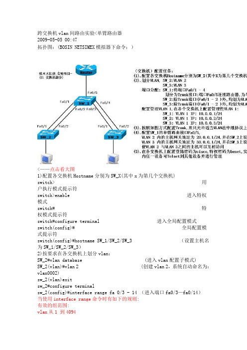
跨交换机vlan间路由实验<单臂路由器2009-05-05 00:47拓扑图:(BOSIN NETSIMEX模拟器下命令:)<——点击看大图1)配置各交换机Hostname分别为SW_X(其中x为第几个交换机)switch> 用户执行模式提示符switch>enable 进入特权模式switch# 特权模式提示符switch#configure terminal 进入全局配置模式switch(config)# 全局配置模式提示符switch(config)#hostname SW_1/SW_2/SW_3 (设置主机名为SW_1/SW_2/SW_3)2)按要求在各交换机上划分vlan:SW_2#vlan database (进入vlan配置子模式)SW_2(vlan)#vlan 2 (创建vlan 2,系统自动命名为:vlan0002)sw_2(vlan)exitsw_2#configure terminalsw_2(config)#interface range fa 0/3 - 14 (进入端口fa0/3—fa0/14)当使用interface range命令时有如下的规则:有效的组范围:vlan从1 到4094fastethernet 槽位/{first port} - {last port}, 槽位为0 gigabitethernet槽位/{first port} - {last port},槽位为0port-channel port-channel-number - port-channel-number, port-channel 号从1到64端口号之间需要加入空格,如:interface range fastethernet 0/1 – 5 是有效的,而interface range fastethernet 0/1-5 是无效的.interface range 命令只能配置已经存在的interface vlan所有在同一组的端口必须是相同类别的。
华为交换机实现VLAN间路由实例

进入所有分配的端口,将该端口分配给某VLAN
Switch(config)#interface port-number //指定欲配置接口
Switch(config-if)#switchport mode access //规定该端口为访问链路
二、案例分析
原有的两个VLAN之间不能通信,这是由于二层交换机不具备三层交换的能力,不能在VLAN之间提供路由。
如果需要为两个VLAN之间提供路由,则必须在网络中添加路由器或者三层交换机这样的路由设备。
而由于该公司主机太多,现有两个交换机已经接满,无法再连接主机,所以需要购置三层交换机来接入增加的主机,同时为两个VLAN之间提供路由能力,连通两个VLAN的主机。
下面是一个在三层交换机上为VLAN做路由的简单配置:
Router(config)#interface vlan1
Router(config-if)#ip add 192.168.1.1 255.255.255.0
Router(config-if)#interface vlan2
Router(config-if)#ip add 192.168.2.1 255.255.255.0
其中interface vlan1和interface vlan2是逻辑上的接口,从接口的名字我们也能看出其与VLAN之间的对应关系。基本上,只要在这些逻辑接口上分配了属于VLAN所对应子网的IP地 址,就可以简单的实现VLAN间的通信了。 另外,在三层交换机上需要使用如下命令打开其路由功能:
Router(config)#ip routing
[Switch3]vlan 2 //创建vlan 2
[Switch3-vlan2] port e 1/0/2
实验报告—VLAN间路由与三层交换机配置

实验:VLAN间路由配置
移动1331 43 林观科
⏹实验目的
1、掌握三层交换机的工作原理
2、学习配置三层交换机的命令和步骤
⏹实验要求
1、拓扑与地址规划;
2、三层交换机和VTP基本配置
3、验证连通性,并给出配置清单
⏹实验拓扑
⏹实验设备(环境、软件)
三层交换机1台,交换机2台,直通线7条,Pc机4台。
软件:GNS3模拟器
⏹实验设计到的基本概念和理论
将三层交换机配置成VTP的server,其他普通交换机配置成VTP CLIENT mode,从而实现各个vlan间的通信。
⏹实验过程和主要步骤
1、绘制网络拓扑和地址规划
地址规划如下:
2、Switch1的配置情况如下所示:
3、Switch2的配置情况如下所示:
4、Router1的配置情况如下所示:
5、显示路由器Router1上的路由表如下:
6、验证4个PC间通信状况
PC1到PC0的通信,PC1到PC2的通信,PC1到PC3的通信状况如下:
总结:
通过这次的实验,我懂得了如何实际地配置三层交换机的简单命令,从而实现不同vlan间的通信,同时深入的了解了路由器在不同区域间的进行通信的重要性。
知道的子接口与路由器中实际的接口的区别与联系,接口是路由器的实际物理接口,而子接口是路由器的逻辑接口(通过GNS3软件实现的),路由器在vlan间实现通信的过程,如何将信息进行传送。
此次实验的过程也不是那么的顺利,但是通过查找有关资料与仔细的看书还有和同学相互讨论才使实验顺利进行,从中了解了不少的知识。
三层交换机vlan间路由原理

三层交换机vlan间路由原理
三层交换机是一种在局域网中实现 VLAN 间路由的网络设备。
它能够在不同的 VLAN 之间提供互通的能力,实现不同子网之间的数据转发和通信。
三层交换机通过将不同 VLAN 的数据包转发到正确的目的地来实现 VLAN 间的路由。
当一个数据包从一个 VLAN 发出并传入三层交换机时,交换机根据目标IP 地址来决定数据包的下一个目的地。
它使用路由表来确定应该将数据包发送到哪个 VLAN,并相应地更新数据包的 VLAN 标签。
三层交换机还可以使用虚拟局域网接口(SVI)来进行 VLAN 间的路由。
SVI 是三层交换机上配置的虚拟接口,它代表一个 VLAN。
三层交换机可以为每个VLAN 配置一个 SVI,并通过这些 SVI 实现数据包的路由和转发。
三层交换机使用基于 IP 的路由协议,如 OSPF、EIGRP 或静态路由,来决定数据包的路由路径。
它从与其他网络设备交换的路由信息中学习到的目的地网络和最佳路径,可以有效地选择数据包的下一跳。
三层交换机还支持网络地址转换(NAT),可以将内部网络的私有 IP 地址转换为公共 IP 地址,以便实现与外部网络的通信。
这种转换确保内部数据包能够安全地进出网络边界。
总之,三层交换机通过使用 VLAN 间的路由功能,可以实现不同子网之间的互通和数据转发。
它使用路由表、SVI 和路由协议来决定数据包的路由路径,同时支持网络地址转换,为网络提供更大的灵活性和扩展性。
vlan间通信三层交换机路由实验报告.doc

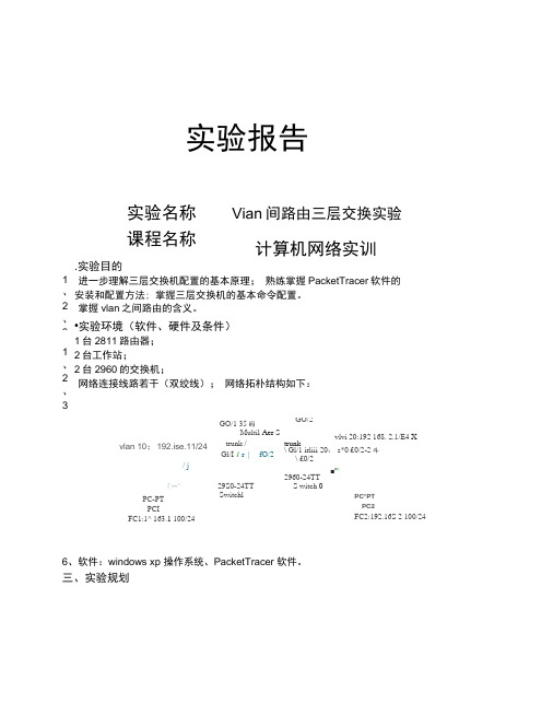
vlan间通信三层交换机路由实验报告实验报告实验名称Vlan间路由三层交换实验课程名称计算机网络实训一.实验目的1、进一步理解三层交换机配置的基本原理;2、熟练掌握PacketTracer软件的安装和配置方法;3、掌握三层交换机的基本命令配置。
4、掌握vlan之间路由的含义。
二.实验环境(软件、硬件及条件)1、1台2811路由器;2、2台工作站;3、2台2960的交换机;4、网络连接线路若干(双绞线);5、网络拓朴结构如下:6、软件:windowsxp操作系统、PacketTracer软件。
三、实验规划1、启动PacketTracer软件,选择路由器、PC 构成以上拓扑结构,画出拓扑图,然后用PacketTracer软件对此网络进行配置。
2、配置各个局域网;1)配置PC1、PC2的IP和网关,子网掩码PC1配置:选择PacketTracer软件中的Desktop,配置如图同理根据规划表和拓扑图配置好PC2机的IP地址、子网掩码和网关。
2)配置路由器的Ethernetport的以太网的IP地址、子网掩码:三层交换机3560的配置命令如下:交换机2960Switch1的配置命令如下:交换机2960Switch0的配置命令如下:4、验证。
在PC1上执行两次ping命令对PC2进行连通性检测验证,结果如下:以上结果说明PC1和PC2能正常通信,说明各交换机Switch配置正确。
五、实验分析:1、对路三层交换机路由表进行察看结果如下:交换机路由表收敛到192.168.1.0、192.168.2.0Pc1pingpc2通。
进一步说明配置成功。
六、实验心得1、进一步对认识了vlan间的路由;2、能够较熟练地利用PacketTracer软件进行简单网络拓扑结构图的绘制,以及按照拓扑图进行基本配置;3、vlan之间要进行通信必须要经过三层设备,带有路由功能的设备。
vlan间通信三层交换机路由实验报告

实验报告.实验目的进一步理解三层交换机配置的基本原理; 熟练掌握PacketTracer 软件的安装和配置方法; 掌握三层交换机的基本命令配置。
掌握vlan 之间路由的含义。
•实验环境(软件、硬件及条件) 1台2811路由器; 2台工作站; 2台2960的交换机; 网络连接线路若干(双绞线); 网络拓朴结构如下:6、软件:windows xp 操作系统、PacketTracer 软件。
三、实验规划vlan 10;192.ise.11/24GO/2 vlvi 20:192 168. 2.1/E4 Xtrunk \ Gl/1 irliii 20: s*0 £0/2-2斗\ £0/2 ■"12960-24TT S witch 0GO/1 35 码Multil Aer Strunk /Gl/I 1 r | fO/2/ j「一^29S0-24TTSwitchlPC-PT PCIFC1:1^ 163.1 100/24PC*PT PC2FC2:192.16S 2 100/24实验名称 课程名称Vian 间路由三层交换实验计算机网络实训1、 2、31、 2、 3、间路由-二层交换 1*—二层交换机:SW3560GiO/1trunkGiO/2 trunkvlan 10 192.168. L 1/24 swl fO/2-24vlan 20192.16& 2.1/24sw2 fO/2-24交换机「Swl 2960Gil/ItrunkfO/2->PCl交换机:SwO 2960Gil/1trunkfO/2->PC2IPC1: 192.168.1.100/24]PC2: 192.168. 2.100/241、启动PacketTracer 软件,选择路由器、PC 构成以上拓扑结构,画出拓扑图,vlan 10:192. 169. 1. 1/24 trunk PC-PTPCIPCI :192.16B.1 100/24然后用PacketTracer 软件对此网络进行配置。
vlan间通信实验报告

vlan间通信实验报告实验目的:本次实验旨在通过搭建虚拟局域网(VLAN)网络,掌握VLAN的基本原理和配置方法,以及学习如何在不同VLAN之间进行通信。
实验环境:1.三台计算机:PC1、PC2、PC32.三个交换机:SW1、SW2、SW33.网线若干4.路由器一台实验过程:1.配置交换机首先需要将三个交换机进行基本配置。
我们使用命令行方式进行配置。
(1)设置管理口IP地址和子网掩码SW1(config)#interface vlan 1SW1(config-if)#ip address 192.168.0.1 255.255.255.0 SW2(config)#interface vlan 1SW2(config-if)#ip address 192.168.0.2 255.255.255.0 SW3(config)#interface vlan 1SW3(config-if)#ip address 192.168.0.3 255.255.255.(2)开启交换机端口连接状态检测功能SW1(config)#spanning-tree portfast bpduguard default SW2(config)#spanning-tree portfast bpduguard default SW3(config)#spanning-tree portfast bpduguard default(3)将端口划分到不同的VLAN中在这里我们将PC1和PC2放置在VLAN10中,将PC3放置在VLAN20中。
SW1(config)#vlan 10SW1(config-vlan)#name vlan10SW1(config-vlan)#exitSW1(config)#vlan 20SW1(config-vlan)#name vlan20SW1(config-vlan)#exitSW2(config)#vlan 10SW2(config-vlan)#name vlan10SW2(config-vlan)#exitSW2(config)#vlan 20SW2(config-vlan)#name vlan20SW2(config-vlan)#exitSW3(config)#vlan 10SW3(config-vlan)#name vlan10SW3(config-vlan)#exitSW3(config)#vlan 20SW3(config-vlan)#name vlan20SW3(config-vlan)#(4)配置交换机端口我们需要将PC1和PC2的接口连接到交换机的Fa0/1和Fa0/2端口,将PC3的接口连接到交换机的Fa0/3端口。
配置VLAN之间的路由

二层交换交换上配置VLAN之间的路由拓扑图如下:要求:1.创建VLAN2 、VLAN3;2.把接口F0/2、F0/3划入VLAN2,接口F0/4、F0/5划入VLAN3;3.把F0/1配置成trunk模式;4.在route上配置合适的DHCP服务,为其所连接的PC提供IP地址服务。
5.在路由器上划分子接口使不同VLAN之间可以通信。
一、我们首先先在交换机上进行配置Switch>enableSwitch#vlan databaseSwitch#vlan 2Switch(vlan)#exitSwitch#vlan 3Switch(vlan)#exitSwitch#conf tEnter configuration commands,one per line. End with CNTL/zSwitch(config)#hostname S1S1(config)#int range f0/2-3S1(config-if-range)#switchport mode accessS1(config-if-range)#switchport access vlan 2S1(config-if-fange)#exitS1(config)#int range f0/4-5S1(config-if-range)#switchport mode accessS1(config-if-range)#switchport access vlan 3S1(config-if-range)#exitS1(config)#interface f0/1S1(config-if)#switchport mode trunkS1(config-if)#exitS1(config)#end二、在路由器上进行配置Router>enRouter#configure terminalEnter configuration commands, one per line. End with CNTL/Z.Router(config)#int f0/0Router(config-if)#no shutdownRouter(config-if)#no ip addressRouter(config-if)#int f0/0.1Router(config-subif)#encapsulation dot1Q 2Router(config-subif)#ip address 192.168.10.1 255.255.255.0Router(config-subif)#no shRouter(config-subif)#exitRouter(config)#int f0/0.2Router(config-subif)#encapsulation dot1Q 3Router(config-subif)#ip add 192.168.20.1 255.255.255.0Router(config-subif)#no shutdownRouter(config-subif)#exitRouter(config)#ip dhcp pRouter(config)#ip dhcp pool vlan2Router(dhcp-config)#network 192.168.10.0 255.255.255.0Router(dhcp-config)#default-router 192.168.10.1Router(dhcp-config)#exitRouter(config)#ip dhcp pool vlan3Router(dhcp-config)#network 192.168.20.1 255.255.255.0Router(dhcp-config)#default-router 192.168.20.1Router(dhcp-config)#exitRouter(config)#ip dhcp excluded-address 192.168.10.1Router(config)#ip dhcp excluded-address 192.168.20.1Router(config)#end三、在主机上修改IP Configuration 选择DHCP选项,自动获取IP地址。
[计算机]vlan间路由的实验报告
![[计算机]vlan间路由的实验报告](https://img.taocdn.com/s3/m/0611cbea05087632311212cf.png)
实验三 Vlan之间的路由实验报告一、实验名称:Vlan之间的路由二、实验目的:通过三层交换机,使分别属于两个Vlan的两台计算机之间能相互通信三、实验设备:三层交换机一部,二层交换机一部,计算机两部,双绞线、交叉线若干如图:四、实验过程:(一)建立拓扑1、首先,对PC0和PC1两台计算机设置如下图的网络地址;2、连接好设备,构成一个简单的拓扑结构。
现在进行一次连通性的检测;可以看出,现在两台计算机是没办法进行互相连通的;(二)两层交换机的设置1、对两层交换机switch2进行简单的基本设置,先创建两个vlan,有vlan 10和vlan 30,并把连接PC0的接口fa/1划入vlan 10,把连接PC1的接口fa/2划入vlan 30,如下图:2、输入show vlan命令查看虚拟局域网的相关信息,看出建立vlan成功了,接口的划入也成功了;(三)三层交换机的设置1、同样要对三层交换机做一些命令的设置,还是先建立两个虚拟局域网,vlan 10和vlan 30 ,见下图:2、为了能实现实验目的,接下来是要进行对三层交换机中vlan子接口IP地址的配置。
设置的关键所在是,vlan子接口的IP地址要与两台计算机配置的IP地址同属一个网络,vlan子接口的IP地址要作为计算机的网关。
3、现在查看路由的IP,输入show ip route 命令;从Gateway of last resort is not set可以得到信息,现在的网关提示说没有设置,我还需要进一步设置命令;4、查看一下虚拟局域网的信息,这个是vlan 10的基本信息,有一句写着line protocol is down,此时的连接协议是关闭的;vlan 30的信息也一样;5、此时要进行关键的配置,进入互连接口fa0/24的接口模式,在对接口fa0/24设置vlan中继之前,需要设置该接口的封装模式。
关键语句是switchport trunk encapsulation dot1q,这样line protocol变成启动了;6、再查看一次路由的ip,也可以看到能够连接上了;7、下面是查看trunk模式的信息;(三)连通性检测1、在PC0运行ipconfig命令查看网络地址,再对PC1运行ping命令;可见,现在两台计算机是可以连通的;2、查看一下MAC地址表,能看出数据的传输路线;五、实验结论:每个vlan都是独立的广播域,所以在默认情况下,不同vlan中的计算机之间无法通信,使用vlan间路由的方法可以实现连通。
VLAN的基本配置实验

虚拟局域网配置Ⅰ.实验目标:掌握VLAN技术。
Ⅱ.实验环境:WINDOWS XP 锐捷网络实验室Ⅲ.基本内容:验证在同一VLAN的计算机能相互通信、在不同VLAN的计算机不能通信Ⅳ.实验原理:VLAN交换技术Ⅴ.实验设备:交换机,计算机。
Ⅺ.实验内容:一、实验目的1.掌握划分VLAN的目的;2.掌握基于交换机端口配置VLAN的方法;3.掌握跨交换机实现VLAN的方法。
二、实验任务1.使用交换机的命令行界面;2.创建VLAN;3.将交换机端口分配到VLAN;4.查看VLAN信息。
三、实验步骤(一)交换机端口隔离1、将pc1和pc2连接到同一台交换机上如图5-1所示F0/1 F0/2VLAN 10 VLAN 20Pc1 pc2图5-12、配置好pc1和pc2的ip地址、子网掩码此时,验证两台pc可以互相ping通。
3、创建VLAN在特权模式下输入如下命令创建VLAN 10,名称为test1。
Configure terminalVlan 10Name test1同上创建VLAN 20,名称为test2。
4、显示VLAN 信息Show vlan5、将接口分配到VLANConfigure terminalInterface fastethernet 0/1Switchport access vlan 10同上将端口2加入vlan 20中。
6、验证pc1和pc2互相ping不通注意:⑴ vlan 1属于系统的默认VLAN,不可以被删除;⑵删除某个VLAN,用no命令,如:no vlan 10⑶删除当前某个VLAN时,先将属于该VLAN的端口加入别的VLAN,再删除VLAN。
(二)跨交换机实现VLAN(选做,不作统一要求)1、如图5-2所示进行网络连接A BF0/24 F0/24F0/1F0/1 F0/2VLAN 10 VLAN 20 VLAN 10PC1 PC2 PC3图5-22、配置好PC1、PC2、PC3的ip地址和子网掩码此时,验证三台pc可以互相ping通。
VLAN间的路由配置实验报告

“计算机网络实验”-实验报告实验序号:实验项目名称:VLAN之间的路由配置实验台号:三实验组号:实验时间:5月15日8:00—16:15实验成员及分工:实验目的:实验1,熟悉交换机的命令,掌握交换机的配置,学会如何划分vlan 子网。
实验2,进一步熟悉各个设备的配置,同时掌握路由控制链表的配置。
实验设备和环境:设备:两台pc,两台路由器,一台3750交换机,两台2950交换机,若干设备连接线环境:安全的网络环境实验过程及步骤:(可以另附页,给出相应的实验环境拓扑图和实验说明)实验总结:(遇到的问题、解决方法、收获和体会,可以另附页)实验器材、验收同学:实验责任人:实验记录人:报告执笔人:实验完成时间:验收同学:实验小组成员签名:指导教师签名: 成绩:一、VLAN 之间的路由配置Switch>enable Switch#config tEnter configuration commands, one per line. End with CNTL/Z. Switch(config)#hostname c3750 c3750(config)#exit c3750#00:01:19: %SYS-5-CONFIG_I: Configured from console by console c3750#vlan b00:01:25: %LINEPROTO-5-UPDOWN: Line protocol on Interface Vlan1, changed state t o upc3750#vlan basedata ^% Invalid input detected at '^' marker.c3750#vlan database% Warning: It is recommended to configure VLAN from config mode, as VLAN database mode is being deprecated. Please consult user documentation for configuring VTP/VLAN in config mode.c3750(vlan)#vlan 2 name market交换机3750IP 地址: 192.168.2.2 默认网关: 192.168.2.1交换机2950IP 地址: 192.168.3.5 默认网关: 192.168.3.1路由器2811fa1/0/24fa1/0/23fa0/24fa 0/0图9.5 采用单臂路由实现VLAN 之间的路由VLAN 2 modified:Name: marketc3750(vlan)#vlan 3 name developVLAN 3 modified:Name: developc3750(vlan)#end^% Invalid input detected at '^' marker.c3750(vlan)#exitAPPL Y completed.Exiting....c3750#config tEnter configuration commands, one per line. End with CNTL/Z.c3750(config)#inter range f0/1 -4^% Invalid input detected at '^' marker.c3750(config)#inter range f1/1 -4^% Invalid input detected at '^' marker.c3750(config)#inter range fa1/1 -4^% Invalid input detected at '^' marker.c3750(config)#interface range fa1/0/1 -4c3750(config-if-range)#switchport access vlan 2c3750(config-if-range)#interface range fa1/0/5 -8c3750(config-if-range)#switchport access vlan 3c3750(config-if-range)#exitc3750(config)#inter fa1/0/24c3750(config-if)#switchport trunk encap dot1qc3750(config-if)#switchport mode trunkc3750(config-if)#interface fa1/0/23c3750(config-if)#switchport tunk encap dot1q^% Invalid input detected at '^' marker.c3750(config-if)#switchport trunk encap dot1qc3750(config-if)#switchport mode trunkc3750(config-if)#e00:07:57: %LINEPROTO-5-UPDOWN: Line protocol on Interface FastEthernet1/0/23, changed state to downc3750(config-if)#exitc3750(config)#00:08:00: %LINEPROTO-5-UPDOWN: Line protocol on Interface FastEthernet1/0/23, changed state to upc3750(config)#% Please answer 'yes' or 'no'.Would you like to enter the initial configuration dialog? [yes/no]:% Please answer 'yes' or 'no'.Would you like to enter the initial configuration dialog? [yes/no]: noPress RETURN to get started!Router>Router>enableRouter#config tEnter configuration commands, one per line. End with CNTL/Z.Router(config)#inter f0/0Router(config-if)#no shutdownRouter(config-if)#Router(config-if)#*May 15 03:16:07.219: %LINK-3-UPDOWN: Interface FastEthernet0/0, changed state to up*May 15 03:16:10.219: %LINEPROTO-5-UPDOWN: Line protocol on Interface FastEthernet0/0, changed state to upRouter(config-if)#interf f0/0.2Router(config-subif)#encap dot1q 2Router(config-subif)#ip address% Incomplete command.Router(config-subif)#ip address 192.168.2.1 255.255.255.0Router(config-subif)#no shutdownRouter(config-subif)#inter f0/0.3Router(config-subif)#encap dot1q 3Router(config-subif)#ip address 192.168..3.1 255.255.255.0^% Invalid input detected at '^' marker.Router(config-subif)#ip address 192.168.3.1 255.255.255.0Router(config-subif)#exitRouter(config)#inter f0/0.3Router(config-subif)#no shutdownRouter(config-subif)#endRouter#*May 15 03:19:17.519: %SYS-5-CONFIG_I: Configured from console by console% Please answer 'yes' or 'no'.Would you like to enter the initial configuration dialog? [yes/no]: nPress RETURN to get started!Switch>00:13:51: %LINK-5-CHANGED: Interface Vlan1, changed state to administratively down00:13:52: %LINEPROTO-5-UPDOWN: Line protocol on Interface Vlan1, changed state to downe% Ambiguous command: "e"Switch>enableSwitch#config tEnter configuration commands, one per line. End with CNTL/Z.Switch(config)#hostname c2950c2950(config)#exitc2950#v00:14:18: %SYS-5-CONFIG_I: Configured from console by console]% Unknown command or computer name, or unable to find computer addressc2950#vlan database% Warning: It is recommended to configure VLAN from config mode,as VLAN database mode is being deprecated. Please consult user documentation for configuring VTP/VLAN in config mode.c2950(vlan)#vlan 2 name marketVLAN 2 modified:Name: marketc2950(vlan)#vlan 3 name developVLAN 3 modified:Name: developc2950(vlan)#vtp clientDevice mode already VTP CLIENT.c2950(vlan)#exitIn CLIENT state, no apply attempted.Exiting....c2950#config tEnter configuration commands, one per line. End with CNTL/Z.c2950(config)#inter range fa0/1 -4c2950(config-if-range)#switchport access vlan 2c2950(config-if-range)#inter range fa0/0/5 -8^% Invalid input detected at '^' marker.c2950(config)#inter range fa0/5 -8c2950(config-if-range)#switchport access vlan 3c2950(config-if-range)#interface f0/24c2950(config-if)#switchport mode trunkc2950(config-if)#exitc2950(config)#endc2950#00:18:36: %SYS-5-CONFIG_I: Configured from console by console二、路由访问控制列表配置未添加acl 之前 R1的配置Router>enable Router#config tEnter configuration commands, one per line. End with CNTL/Z. Router(config)#hostname ri ri(config)#inter f0/0ri(config-if)#ip address 192.168.1.1 255.255.255.0交换机2950-A交换机2950-B路由器r1路由r2IP 地址: 192.168.1.2 默认网关: 192.168.1.1S0/0/0S0/1fa0/1192.168.1.1192.168.2.1fa0/1 192.168.12.2192.168.12.1IP 地址: 192.168.2.2 默认网关: 192.168.2.1图8.20 采用交换机的路由器配置环境ri(config-if)#no shutdown%LINK-5-CHANGED: Interface FastEthernet0/0, changed state to up%LINEPROTO-5-UPDOWN: Line protocol on Interface FastEthernet0/0, changed state to upri(config-if)#inter s0/0/0^% Invalid input detected at '^' marker.ri(config-if)#exitri(config)#inter s0/0/0^% Invalid input detected at '^' marker.ri(config)#inter s0/0/1^% Invalid input detected at '^' marker.ri(config)#inter s0/0ri(config-if)#ri(config-if)#exitri(config)#interface Serial0/0ri(config-if)#ri(config-if)#exitri(config)#interface Serial0/1ri(config-if)#ri(config-if)#exitri(config)#interface Serial0/0ri(config-if)#ip address 192.168.12.1 255.255.255.0ri(config-if)#encap pppri(config-if)#clock rate 64000ri(config-if)#no shutdown%LINK-5-CHANGED: Interface Serial0/0, changed state to downri(config-if)#no shutdownri(config-if)#ri(config-if)#exitri(config)#interface Serial0/0ri(config-if)#exitri(config)#exit%SYS-5-CONFIG_I: Configured from console by consoleri#config tEnter configuration commands, one per line. End with CNTL/Z.ri(config)#router ripri(config-router)#network 192.168.1.0ri(config-router)#network 192.168.12.0ri(config-router)#end%SYS-5-CONFIG_I: Configured from console by consoleri#show ip routeCodes: C - connected, S - static, I - IGRP, R - RIP, M - mobile, B - BGPD - EIGRP, EX - EIGRP external, O - OSPF, IA - OSPF inter areaN1 - OSPF NSSA external type 1, N2 - OSPF NSSA external type 2E1 - OSPF external type 1, E2 - OSPF external type 2, E - EGPi - IS-IS, L1 - IS-IS level-1, L2 - IS-IS level-2, ia - IS-IS inter area* - candidate default, U - per-user static route, o - ODRP - periodic downloaded static routeGateway of last resort is not setC 192.168.1.0/24 is directly connected, FastEthernet0/0ri#%LINK-5-CHANGED: Interface Serial0/0, changed state to upri#show ip routeCodes: C - connected, S - static, I - IGRP, R - RIP, M - mobile, B - BGPD - EIGRP, EX - EIGRP external, O - OSPF, IA - OSPF inter areaN1 - OSPF NSSA external type 1, N2 - OSPF NSSA external type 2E1 - OSPF external type 1, E2 - OSPF external type 2, E - EGPi - IS-IS, L1 - IS-IS level-1, L2 - IS-IS level-2, ia - IS-IS inter area* - candidate default, U - per-user static route, o - ODRP - periodic downloaded static routeGateway of last resort is not setC 192.168.1.0/24 is directly connected, FastEthernet0/0ri#ri#configure terminalEnter configuration commands, one per line. End with CNTL/Z.ri(config)#interface Serial0/0ri(config-if)#ri(config-if)#exitri(config)#ri(config)#ri(config)#router ripri(config-router)#ri#%SYS-5-CONFIG_I: Configured from console by consoleri#ping 192.168.12.1Type escape sequence to abort.Sending 5, 100-byte ICMP Echos to 192.168.12.1, timeout is 2 seconds: .....Success rate is 0 percent (0/5)ri#show interFastEthernet0/0 is up, line protocol is up (connected)Hardware is Lance, address is 00e0.f9aa.eb23 (bia 00e0.f9aa.eb23) Internet address is 192.168.1.1/24MTU 1500 bytes, BW 100000 Kbit, DLY 100 usec,reliability 255/255, txload 1/255, rxload 1/255Encapsulation ARPA, loopback not setARP type: ARPA, ARP Timeout 04:00:00,Last input 00:00:08, output 00:00:05, output hang neverLast clearing of "show interface" counters neverInput queue: 0/75/0 (size/max/drops); Total output drops: 0 Queueing strategy: fifoOutput queue :0/40 (size/max)5 minute input rate 0 bits/sec, 0 packets/sec5 minute output rate 0 bits/sec, 0 packets/sec0 packets input, 0 bytes, 0 no bufferReceived 0 broadcasts, 0 runts, 0 giants, 0 throttles0 input errors, 0 CRC, 0 frame, 0 overrun, 0 ignored, 0 abort0 input packets with dribble condition detected1 packets output, 52 bytes, 0 underruns0 output errors, 0 collisions, 1 interface resets0 babbles, 0 late collision, 0 deferred0 lost carrier, 0 no carrierri#show interFastEthernet0/0 is up, line protocol is up (connected)Hardware is Lance, address is 00e0.f9aa.eb23 (bia 00e0.f9aa.eb23) Internet address is 192.168.1.1/24MTU 1500 bytes, BW 100000 Kbit, DLY 100 usec,reliability 255/255, txload 1/255, rxload 1/255Encapsulation ARPA, loopback not setARP type: ARPA, ARP Timeout 04:00:00,Last input 00:00:08, output 00:00:05, output hang neverLast clearing of "show interface" counters neverInput queue: 0/75/0 (size/max/drops); Total output drops: 0Queueing strategy: fifoOutput queue :0/40 (size/max)5 minute input rate 0 bits/sec, 0 packets/sec5 minute output rate 0 bits/sec, 0 packets/sec0 packets input, 0 bytes, 0 no bufferReceived 0 broadcasts, 0 runts, 0 giants, 0 throttles0 input errors, 0 CRC, 0 frame, 0 overrun, 0 ignored, 0 abort0 input packets with dribble condition detected1 packets output, 52 bytes, 0 underruns0 output errors, 0 collisions, 1 interface resets0 babbles, 0 late collision, 0 deferred0 lost carrier, 0 no carrier0 output buffer failures, 0 output buffers swapped outSerial0/0 is up, line protocol is down (disabled)Hardware is HD64570Internet address is 192.168.12.1/24MTU 1500 bytes, BW 128 Kbit, DLY 20000 usec,reliability 255/255, txload 1/255, rxload 1/255Encapsulation PPP, loopback not set, keepalive set (10 sec)LCP ClosedClosed: LEXCP, BRIDGECP, IPCP, CCP, CDPCP, LLC2, BACPLast input never, output never, output hang neverLast clearing of "show interface" counters never--More--%LINEPROTO-5-UPDOWN: Line protocol on Interface Serial0/0, changed state to upInput queue: 0/75/0 (size/max/drops); Total output drops: 0Queueing strategy: weighted fairOutput queue: 0/1000/64/0 (size/max total/threshold/drops)ri#show ip routeCodes: C - connected, S - static, I - IGRP, R - RIP, M - mobile, B - BGPD - EIGRP, EX - EIGRP external, O - OSPF, IA - OSPF inter areaN1 - OSPF NSSA external type 1, N2 - OSPF NSSA external type 2E1 - OSPF external type 1, E2 - OSPF external type 2, E - EGPi - IS-IS, L1 - IS-IS level-1, L2 - IS-IS level-2, ia - IS-IS inter area* - candidate default, U - per-user static route, o - ODRP - periodic downloaded static routeGateway of last resort is not setC 192.168.1.0/24 is directly connected, FastEthernet0/0R 192.168.2.0/24 [120/1] via 192.168.12.2, 00:00:08, Serial0/0C 192.168.12.0/24 is directly connected, Serial0/0R2的配置Router>enableRouter#hostname r2^% Invalid input detected at '^' marker.Router#config tEnter configuration commands, one per line. End with CNTL/Z.Router(config)#hostname r2r2(config)#interfa f0/0\^% Invalid input detected at '^' marker.r2(config)#inter f0/0r2(config-if)#ip address 192.168.2.1 255.255.255.0r2(config-if)#no shutdown%LINK-5-CHANGED: Interface FastEthernet0/0, changed state to up%LINEPROTO-5-UPDOWN: Line protocol on Interface FastEthernet0/0, changed state to upr2(config-if)#inter s0/1r2(config-if)#ip address 192.168.12.2 255.255.255.0r2(config-if)#no shutdown%LINK-5-CHANGED: Interface Serial0/1, changed state to upr2(config-if)#exitr2(config)#router ripr2(config-router)#network 192.168.12.0r2(config-router)#network 192.168.2.0r2(config-router)#end%SYS-5-CONFIG_I: Configured from console by consoler2#show ip routeCodes: C - connected, S - static, I - IGRP, R - RIP, M - mobile, B - BGPD - EIGRP, EX - EIGRP external, O - OSPF, IA - OSPF inter areaN1 - OSPF NSSA external type 1, N2 - OSPF NSSA external type 2E1 - OSPF external type 1, E2 - OSPF external type 2, E - EGPi - IS-IS, L1 - IS-IS level-1, L2 - IS-IS level-2, ia - IS-IS inter area* - candidate default, U - per-user static route, o - ODRP - periodic downloaded static routeGateway of last resort is not setC 192.168.2.0/24 is directly connected, FastEthernet0/0r2#show ip routeCodes: C - connected, S - static, I - IGRP, R - RIP, M - mobile, B - BGPD - EIGRP, EX - EIGRP external, O - OSPF, IA - OSPF inter areaN1 - OSPF NSSA external type 1, N2 - OSPF NSSA external type 2E1 - OSPF external type 1, E2 - OSPF external type 2, E - EGPi - IS-IS, L1 - IS-IS level-1, L2 - IS-IS level-2, ia - IS-IS inter area* - candidate default, U - per-user static route, o - ODRP - periodic downloaded static routeGateway of last resort is not setC 192.168.2.0/24 is directly connected, FastEthernet0/0r2#conf tEnter configuration commands, one per line. End with CNTL/Z.r2(config)#inter s0/1r2(config-if)#encap pppr2(config-if)#e%LINEPROTO-5-UPDOWN: Line protocol on Interface Serial0/1, changed state to upxitr2(config)#exit%SYS-5-CONFIG_I: Configured from console by consoler2#ping 192.168.12.1Type escape sequence to abort.Sending 5, 100-byte ICMP Echos to 192.168.12.1, timeout is 2 seconds:!!!!!Success rate is 100 percent (5/5), round-trip min/avg/max = 2/3/4 msr2#show ip routeCodes: C - connected, S - static, I - IGRP, R - RIP, M - mobile, B - BGPD - EIGRP, EX - EIGRP external, O - OSPF, IA - OSPF inter areaN1 - OSPF NSSA external type 1, N2 - OSPF NSSA external type 2E1 - OSPF external type 1, E2 - OSPF external type 2, E - EGPi - IS-IS, L1 - IS-IS level-1, L2 - IS-IS level-2, ia - IS-IS inter area* - candidate default, U - per-user static route, o - ODRP - periodic downloaded static routeGateway of last resort is not setR 192.168.1.0/24 [120/1] via 192.168.12.1, 00:00:18, Serial0/1C 192.168.2.0/24 is directly connected, FastEthernet0/0C 192.168.12.0/24 is directly connected, Serial0/1r2#标准数据包过滤ri(config)#access-list 99 deny 192.168.2.2 0.0.0.0ri(config)#access-list permit 0.0.0.0 255.255.255.255^% Invalid input detected at '^' marker.ri(config)#interf s0/0ri(config-if)#ip access-group 99 inri(config-if)#end%SYS-5-CONFIG_I: Configured from console by consoleri#show ip access-listStandard IP access list 99deny host 192.168.2.2ri#扩展ip访问链表配置ri(config)#inter s0/0ri(config-if)#no ip access-group 99 inri(config-if)#exitri(config)#access-list 110 deny tcp 192.168.2.2 0.0.0.0 192.168.12.1.0.0.0.0 eq23^% Invalid input detected at '^' marker.ri(config)#access-list 110 deny tcp 192.168.2.2 0.0.0.0 192.168.12.1.0.0.0.0 eq 23^% Invalid input detected at '^' marker.ri(config)#ri(config)#access-list 110 deny tcp 192.168.2.2 0.0.0.0 192.168.12.1 0.0.0.0 eq 23 ri(config)#inter s0/0ri(config-if)#exitri(config)#access-list 110 permit ip any anyri(config)#inter s0/0ri(config-if)#ip access-group 110 inri(config-if)#exitri(config)#exit%SYS-5-CONFIG_I: Configured from console by console ri#show ip access-listStandard IP access list 99deny host 192.168.2.2Extended IP access list 110deny tcp host 192.168.2.2 host 192.168.12.1 eq telnet permit ip any any (2 match(es))ri#。
实训名称:基于三层交换机的vlan之间路由

实训名称:基于三层交换机的vlan之间路由一、实训原理三层交换机有交换机的功能,同时又有路由器的的功能二、实训目的Vlan之间的通信三、实训步骤:拓扑图第一步:配左边的交换机第二步:配右边的交换机第三步:配核心交换机第四步:给PC机配置IP地址具体步骤:第一步:配左边的交换机EnConfVlan 2ExitInt f0/2switchport mode access switchport access vlan 2 int f0/3switchport mode access switchport access vlan 3 int f0/1switchport mode trunk 第二步:配右边的交换机EnConfVlan 4Vlan 5ExitInt f0/2switchport mode access switchport access vlan 4 int f0/3switchport mode access switchport access vlan 5 int f0/1switchport mode trunk 第三步:配核心交换机EnConfVlan 2Vlan 3Vlan 5ExitInt vlan 2Ip add 192.168.2.254 255.255.255.0Int vlan 3Ip add 192.168.3.254 255.255.255.0Int vlan 4Ip add 192.168.4.254 255.255.255.0Int vlan 5Ip add 192.168.5.254 255.255.255.0Exitint range f0/1-2switchport trunk encapsulation dot1q switchport mode trunkexitip routing第四步:给PC机配置IP地址四、实训结果从PC0 ping PC1。
Vlan间路由实验(三层交换机实现法)

今天我们来演示VLAN间路由的实验,配置方法有多种,我们首先来演示利用三层交换机实现V LAN间路由。
其实该实验还有另外一种实现方法:直接在交换机的物理接口配置IP而不用划分VLAN ,下面演示的是在交换机上划分VLAN的实现方法。
实验拓扑图:实验环境说明:1.分别启用路由器R1 、R2和交换机SW1;2.将路由器R1的Fa0/0端口的ip设为:192.168.1.2/24,关闭路由功能,用来模拟PC1,同时将默认网关设为:192.168.1.1;3.将路由器R2的Fa0/0端口的ip设为:192.168.0.2/24,关闭路由功能,用来模拟PC2,同时将默认网关设为:192.168.0.1;4.在交换机SW1上分别划分VLAN14、VLAN15两个VLAN,启用路由功能,用来充当三层交换机;5.将交换机SW1的Fa1/14端口的ip设为:192.168.0.1/24,并将该端口加入到VLAN14中;6.将交换机SW1的Fa1/15端口的ip设为:192.168.1.1/24,并将该端口加入到VLAN15中;实验结果要求:要求两台路由器可以相互ping通对方。
配置过程详解:交换机SW1的配置清单:1.开启交换机的路由功能,充当三层交换机使用SW1(config)#ip routingSW1(config)#exit2.在交换机SW1上划分VLAN:SW1#vlan dataSW1(vlan)#vlan 14SW1(vlan)#vlan 15SW1(vlan)#exit3.将交换机SW1的两个端口分别划入相应的VLAN:SW1(config)#int fa1/14SW1(config-if)#speed 100SW1(config-if)#duplex fullSW1(config-if)#switchport mod accSW1(config-if)#switchport acc vlan 14SW1(config-if)#exitSW1(config)#int fa1/15SW1(config-if)#speed 100SW1(config-if)#duplex fullSW1(config-if)#switchport mod accSW1(config-if)#switchport acc vlan 15SW1(config-if)#exit4.分别为每个VLAN设置ip:SW1(config)#int vlan 14SW1(config-if)#ip add 192.168.0.1 255.255.255.0SW1(config-if)#no shutSW1(config-if)#exitSW1(config)#int vlan 15SW1(config-if)#ip add 192.168.1.1 255.255.255.0SW1(config-if)#no shutSW1(config-if)#exit路由器R1的配置清单:R1(config)#no ip routing //关闭路由功能R1(config)#ip default-gateway 192.168.1.1 //配置默认网关R1(config)#int fa0/0 //进入端口模式R1(config-if)#speed 100 //设置速率R1(config-if)#duplex full //设为全双工模式R1(config-if)#ip add 192.168.1.2 255.255.255.0 //配置ip地址和子网掩码R1(config-if)#no shut //启动端口R1(config-if)#exit路由器R2 的配置清单:R2(config)#no ip routingR2(config)#ip default-gateway 192.168.0.1R2(config)#int fa0/0R2(config-if)#speed 100R2(config-if)#duplex fullR2(config-if)#ip add 192.168.0.2 255.255.255.0R2(config-if)#no shutR2(config-if)#exit验证实验结果:R1pingR2:R1r#ping 192.168.0.2Type escape sequence to abort.Sending 5, 100-byte ICMP Echos to 192.168.0.2, timeout is 2 seconds:!!!!!Success rate is 100 percent (5/5), round-trip min/avg/max = 120/162/216 ms R2pingR1:R2#ping 192.168.1.2Type escape sequence to abort.Sending 5, 100-byte ICMP Echos to 192.168.1.2, timeout is 2 seconds:!!!!!Success rate is 100 percent (5/5), round-trip min/avg/max = 120/137/188 ms OK ,到此VLAN间路由实验(三层交换机实现法)就圆满完成了。
交换机的vlan间的路由配置

五、层交换机的vlan间的路由配置实验课程:计算机网络工程实验项目:层交换机的vlan间的路由配置系:计算机系班级:08网络工程姓名:熊江红学号:200810803050一、实训目的和要求1、掌握交换机VLAN的概念、原理、划分方法。
2、掌握Trunking技术的概念。
4、掌握交换机配置VLAN、Trunk的方法。
二、实训内容实现多个vlan之间的通信。
三、命令格式∙定义VLAN并设置VLAN名称设置VLAN共有两个步骤,这是第一步。
VLAN的号码要从2开始,因为在默认情况下,交换机的所有端口都已经在VLAN1上。
VLAN名称由用户定义。
Switch#vlan database ………………;进入VLAN配置模式Switch(vlan)#vlan [vlan号码]name [vlan名称]………………;设置VLAN名称和号码∙将VLAN设置应用到端口设置VLAN共有两个步骤,这是第二步。
Switch(config)#int [端口号] ………………;指定VLAN适用的端口Switch(config-if)#switchport mode access ………………;设置该接口为ACCESS模式Switch(config-if)#switchportaccess [vlan号码]………………;把端口分配给VLAN ∙查看VLAN设置情况Switch#show vlan ………………;查看VLAN的设置情况∙设置VTP模式VTP 是VLAN 中继协议,用于维护全网的一致性。
共有三种工作模式:服务器模式,客户模式和透明模式。
VTP 信息宣告以多点传送的方式来进行。
VTP 服务器和客户模式下会同步最新版本的宣告信息。
VTP 信息宣告每隔5分钟或者有变化时发生(30s )。
Switch(vlan)#vtp server ……………… ;定义该交换机为VTP 的服务器模式在server 模式下,交换机具有创建VLAN 、修改VLAN 、删除VLAN 、发送/转发、信息宣告、同步、存贮于NVRAM 等功能。
实验-6.4.1:基本-VLAN-间路由

实验 6.4.1:基本 VLAN 间路由拓扑图地址表设备接口IP 地址子网掩码默认网关(主机名)99 172.17.99.11 255.255.255.0 172.17.99.1S1 VLAN99 172.17.99.12 255.255.255.0 172.17.99.1S2 VLAN99 172.17.99.13 255.255.255.0 172.17.99.1S3 VLAN0/0 172.17.50.1 255.255.255.0 不适用R1 Fa0/1 参见接口配置表不适用R1 FaPC1 网卡172.17.10.21 255.255.255.0 172.17.10.1 PC2 网卡172.17.20.22 255.255.255.0 172.17.20.1 PC3 网卡172.17.30.23 255.255.255.0 172.17.30.1 Server 网卡172.17.50.254 255.255.255.0 172.17.50.1端口分配-交换机 2端口分配网络Fa0/1 – 0/4 802.1q 中继(本征 VLAN 99)172.17.99.0 /24Fa0/5 – 0/10 VLAN 30 – Guest (Default) 172.17.30.0 /24Fa0/11 – 0/17 VLAN 10 – Faculty/Staff 172.17.10.0 /24Fa0/18 – 0/24 VLAN 20 – Students 172.17.20.0 /24接口配置表-路由器 1地址接口分配 IP Fa0/1.1 VLAN1 172.17.1.1 /24Fa0/1.10 VLAN 10 172.17.10.1 /24Fa0/1.20 VLAN 20 172.17.20.1 /24Fa0/1.30 VLAN 30 172.17.30.1 /24Fa0/1.99 VLAN 99 172.17.99.1 /24学习目标完成本实验后,您将能够:•根据拓扑图进行网络布线•清除交换机和路由器配置并将其重新加载到默认状态•在交换 LAN 和路由器上执行基本配置任务•在所有交换机上配置 VLAN 和 VLAN 中继协议 (VTP)•演示并说明创建 VLAN 对第 3 层边界的影响•配置路由器的快速以太网接口,使之支持 802.1q 中继•根据所配置的 VLAN 为路由器配置子接口•演示并说明 VLAN 间路由任务 1:准备网络步骤 1:根据拓扑图所示完成网络电缆连接。
eNSP实验:通过子接口实现子接口VLAN间互通

通过子接口实现不同vlan间互通的例子不同Vlan间互通可以通过vlanif接口来实现,也可以通过路由器的子接口来实现,下面的例子通过子接口来实现vlan 10和vlan 20之间互通,交换机的GE0/0/1接口允许通过vlan 10,vlan 20,在路由器AR1的GE0/0/0上做子接口来实现不同vlan间的互通,拓扑图如下:1. 按图配置好电脑PC1、PC2的地址PC1:IP-192.168.10.2 ,Mask-255.255.255.0,GW-192.168.10.1PC2:IP-192.168.20.2 ,Mask-255.255.255.0,GW-192.168.20.12. S5700交换机的配置如下:sysvlan batch 10 20undo info-center enableinterface vlanif 10qinterface giga 0/0/2port hybrid untagged vlan 10 //设置当前接口为hybrid模式,其中vlan10 出接口时untagged(就是去tag)port hybrid pvid vlan 10 //将Hybrid端口giga 0/0/2的默认VLAN设为10interface giga 0/0/3port hybrid untagged vlan 20port hybrid pvid vlan 20interface giga 0/0/1port link-type trunkport trunk allow-pass vlan 10 20q3. 路由器AR2220配置:在路由器的GE0/0/0接口上配置两个子接口,使子接口能够与vlan进行数据对接,配置如下sysundo info-center enableInfo: Information center is disabled.interface giga 0/0/0.10dot1q termination vid 10ip address 192.168.10.1 24arp broadcast enableinterface giga 0/0/0.20dot1q termination vid 20ip address 192.168.20.1 24arp broadcast enableq。
三层交换机路由配置实验

三层交换机路由配置一、三层交换机VLAN 间路由建立某公司有两个主要部门:某公司有两个主要部门:技术部和销售部,技术部和销售部,技术部和销售部,分处于不同的办公室,分处于不同的办公室,分处于不同的办公室,为了安全为了安全和便于管理对两个部门的主机进行了VLAN 划分,技术部和销售部分处于不同VLAN 。
现由于业务需要销售部和技术部的主机能够相互访问,获得相应资源,两个部门的交换机通过一台三层交换机进行连接。
在交换机上建立2个Vlan :Vlan10分配给技术部及Vlan20分配给销售部。
为了实现两部门的主机能够相互访问,在三层交换机上开启路由功能,并在Vlan10中设置IP 地址为192.168.10.1;在Vlan20中设置IP 地址为192.168.20.1,查看三层交换机路由表,会发现在三层交换机路由表内有2条直连路由信息,实现在不同网络之间路由数据包,从而达到2个部门的主机可以相互访问个部门的主机可以相互访问 ,拓朴图如图所示。
图如图所示。
第1步:开启三层交换机路由功能 Switch#configure terminal Switch(config)#hostname s3550 S3550-24Vlan10Vlan20Fa 0/10Fa 0/20PC1PC2192.168.10.1/24192.168.20.1/24PC1:IP IP地址:地址:地址:192.168.10.10192.168.10.10掩码:掩码:255.255.255.0255.255.255.0网关:网关:192.168.10.1192.168.10.1PC2:IP IP地址:地址:地址:192.168.20.20192.168.20.20掩码:掩码:255.255.255.0255.255.255.0网关:网关:192.168.20.1192.168.20.1S3550(conifg)#ip routing第2步:建立Vlan,并分配端口S3550(conifg)#vlan 10S3550(config-vlan)#name salesS3550(config-vlan)#exitS3550(conifg)#vlan 20S3550(config-vlan)#name technicalS3550(config-vlan)#exitS3550(conifg)#S3550(conifg)#interface fastethernet 0/10S3550(conifg-if)#switchport mode accessS3550(conifg-if)#switchport access vlan 10S3550(conifg-if)#exitS3550(conifg)# interface fastethernet 0/20S3550(conifg-if)#switchport mode accessS3550(conifg-if)#switchport access vlan 20S3550(config-vlan)#exitS3550(config)#第3步:配置三层交换机端口的路由功能S3550(config)#interface vlan 10S3550(conifg-if)#ip address 192.168.10.1 255.255.255.0 S3550(conifg-if)#no shutdownS3550(conifg-if)#exitS3550(config)#interface vlan 20S3550(conifg-if)#ip address 192.168.20.1 255.255.255.0 S3550(conifg-if)#no shutdown S3550(conifg-if)#end S3550#第4步:查看路由表 S3550#show ip route第5步:测试三层交换机Vlan 间路由功能二、三层交换机与路由器间静态路由的建立某校园局域网由若干台交换机构成,某校园局域网由若干台交换机构成,现学校需要将校园网接入互联网,现学校需要将校园网接入互联网,现学校需要将校园网接入互联网,学校学校在出口使用一台路由器连接互联网。
多端口路由VLAN实验

第二步:设置路由的默认网关
第三步:测试 PC0 到 PC5
调试 程序 过程 中发 现的 问题 及解 决办 法
1、出现与路由相连的线路一直是没有联通的 发现如果没有用命令行进行配置,路由的端口默认是关闭的 2、出现下面的情况
检查发现是在配置网关的地方出现错误 实 验 心 得 体 会 1、要搞清楚每一步配置会造成什么结果,不能只是照着配置,不然出了错自己还程名称 实 一、验证 VLAN 配置过程 验 二、验证路由接口过程 目 三、验证 VLAN 间的 IP 分组传输 的 实验 仪器 第一步:连接路线,配置 IP 与默认网关 实 验 内 容 或 上 机 调 试 程 序 局域网 实验名称 多端口路由互联 VLAN
Cisco Packer
- 1、下载文档前请自行甄别文档内容的完整性,平台不提供额外的编辑、内容补充、找答案等附加服务。
- 2、"仅部分预览"的文档,不可在线预览部分如存在完整性等问题,可反馈申请退款(可完整预览的文档不适用该条件!)。
- 3、如文档侵犯您的权益,请联系客服反馈,我们会尽快为您处理(人工客服工作时间:9:00-18:30)。
实验二十 VLAN之间的路由
本实验演示了VLAN及单臂路由的发展历史
要求:1.将交换机划成2个VLAN;
2.把后3个端口加入VLAN2;
3.把路由器的Fa0/0口加入VLAN1,Fa0/1口加入VLAN2口;
4.仅使路由器的Fa0/0与VLAN1连接,配置单臂路由。
说明:1.本实验须2900交换机一台,2621路由器一台,PC机两台
2.将2900交换机的E0/1口与PC1相连,E0/2口与路由器的F0/0相连,
E0/12与PC2相连,F0/27与路由器的F0/1相连
3.PC1的IP地址是192.168.1.2/24,网关是192.168.1.1;
PC2的IP地址是192.168.2.2/24,网关是192.168.2.1;
实验过程:
switch
en
vlan database 建立VLAN
vlan 2 name 2
vlan 3 name 3
vlan 4 name 4
apply
exit
config t
int f0/26 将端口映射到VLAN
switchport access vlan 2
exit
int f0/27
switchport access vlan 2
exit
int fa0/12
switchport access vlan 2
exit
int fa0/11
switchport access vlan 3
no switchport access vlan 3 将端口e0/11从VLAN3中删除
^z
vlan
vlan database 删除VLAN3、VLAN4
no vlan 3
no vlan 4
router
en
config t
int fa0/0
ip address 192.168.1.1 255.255.255.0
no shut
exit
int fa0/1
ip address 192.168.2.1 255.255.255.0
no shut
这时接入VLAN1的配置正确的计算机与接入VLAN2的配置正确的计算机可以正常通信,但多浪费路由器的一个接口和交换机的一个接口,方法不可行
将连接路由器端口Fa0/1与交换机的线断开,形成单臂路由
switch
config t
int E0/2
switchport mode trunk 在端口上配置中继
switchport trunk encapsulation isl 用ISL进行封装
router
config t
int fa0/0
shut
no shut
exit
int fa0/0.1
encapsulation isl 1 将子接口fa0/0设置为trunk,用ISL封装,划分到VLAN1
ip address 192.168.1.1 255.255.255.0(子接口封装后才能进行IP地址的配置) no shut
exit
int fa0/0.2
encapsulation isl 2
ip address 192.168.2.1 255.255.255.0
no shut。
