Force-Impedance Control-a new control strategy of robotic manipulators-Icram'99
机器人英语翻译
机器⼈英语翻译外⽂翻译专业⼯业⼯程学⽣姓名钱晓光班级BD机制082学号0820101205指导教师邱亚兰外⽂资料出处:Applied Mathematics and Computation 185 (2007) 1149–1159附件: 1.外⽂资料翻译译⽂2.外⽂原⽂灵活的双臂空间机器⼈捕捉物体的控制动⼒学译者:钱晓光⽂摘:在本⽂中,我们提出有效载荷的影响,来控制⼀个双臂空间机器⼈灵活的获取⼀个物体。
该拉格朗⽇公式动⼒学模型推导出了机器⼈系统原理。
源⾃初始条件的动⼒学模型模拟了整个系统的获取过程。
⼀个PD控制器设计,其⽬的是为了稳定机器⼈来捕捉对象,动态模拟执⾏例⼦:例:1.机器⼈系统不受控制发⽣撞击,仿真结果表明影响效果。
2.空间机器⼈捕获物体的成功是伟⼤的。
仿真结果表明,该机器⼈关节⾓和机械⼿的迅速程度已经达到稳定。
关键词:柔性臂;空间机器⼈;冲击;动⼒学;PD控制⽅案:圆柱型机器⼈;技能训练1.介绍空间机器⼈将成为⼈类未来在太空检验、装配和检索故障等⽇常⼯作的主要元素。
空间机器⼈满⾜宇航员额外的活动,对这些来说是很有价值的。
然⽽,⼈类⽣活配套设施的成本和时间对航员是有限制的,⾼度风险使空间机器⼈成为宇航员助⼿的选择。
增加设备的流动性, ⾃由飞⾏系统中⼀个或多个臂安装在⼀艘装有推进器⾥,然⽽,扩展推进器的使⽤却得到了极⼤的限制。
⼀个⾃由浮动的操作模式能增加系统的可操作性。
有很多的研究成果对刚性臂空间机器⼈做了研究。
考虑到空间机器⼈以下的特点:轻质量、长臂、重载荷、灵活、有效性等,切应考虑到良好的控制精度和性能。
与此同时,也存在着许多研究动态建模和单臂空间机器⼈灵活控制的成果。
作者描述了碰撞动⼒学建模⽅案的空间机器⼈和研究了多⼿臂灵活空间机器⼈。
吴中书使⽤假设模态⽅法描述了弹性变形,建⽴了动态模型,研究了拉格朗⽇公式和仿真的柔性双臂空间机械臂。
由两个特定操作阶段:影响阶段和撞击阶段。
影响阶段确定了初始条件的对象。
电气工程常见的英文缩写
电气工程常见的英文缩写缩写全称中文AC alternating current 交流电AC automatic control 自动控制ACA accident consequence assessment 事故后果评价ACB air circuit breaker 空气断路器ACC accident 故障、事故ACCUM accumulate accumulate 累计、蓄电池ACDS acourtic crack detection system 声裂纹检测系统ACT/S active side 带电部件、有功部件ACW anti-clockwise 反时针方向ACW anti-clockwise 反时针方向AD analog-digital 模拟-数字AEOD analysis and evaluation of operational data 运行数据分析和管理AFC automatic frequency control automatic following control 自动频率控制:自动跟踪控制AI artificial intelligence 人工智能ALT alternate 交变的、交替的ALTNTR alternator 同步发电机AM ammeter 电流表AMP ampere 安培AN air natural cooled 空气自然冷却AOC automatic overload control 自动过载控制APC automatic plant coordinate control automatic power control 机组自动协调控制:自动功率控制APP appendix auxiliary power plant 附录:辅助电源设备APS acessory power supply 辅助电源APU auxiliary power unit 辅助动力装置:辅助电源设备ARM armature 电枢、衔铁ASR automatic speed run up 自动升速ASU automatic synchronizing unit 自动同步系统AT auxiliary transformer 辅助变压器AUS auxiliary switch 辅助开关AUX auxiliany 辅助、备用A VL automatic voltage control 自动电压控制A VR automatic voltage regulator 自动调压器BAT battery 电池BD block decrease 闭锁减BDUC bus duct 母线导管、母线沟BDV blowdown voltage 击穿电压BF back feed 反馈BHP brake horse power 制动马力BI block increase 闭锁增BKR breaker 断路器BOS back-out system 补偿系统BOT build-operate-tranfer 建造-运行-移交BR brush 电刷、刷子BRKG breaking 断开BYC battery charger 电池充电器CA compressed air 压缩空气CAOS completely automatic operate system 全自动操作系统CAP capactty 电容、出力、容量CAP capacity 容量、功率CA TS computer-aided trouble-shooting 计算机辅助故障查寻CB control buton circuit breaker circuit board 控制钮:线路断路器:电路板CBL line circuit breaker 线路断路器CC charactevistic curve 特性曲线CCW counter-clockwise 反时针CD control desk 控制台CEMF cownta electromotive force 反电动势CG center of gravity 重心CHGR charger 充电器CKT circuit 电路、线路CKW clockwise 顺时针方向CL center line 中心线CLSG closing 关闭、合闸CMR continuous maxinum rating 连续最大功率CNDN condition 工况、参数CO con-out 关闭、切断COEF coefficient 系数CONST constans construction 常数:构造、结构CONT contact control 接点:调节、控制CP control panel 控制板CPD capacitor potential device 电容器分压器CRT cathode-ray tube 阴极射线管CRT circuit 回路CS controlled switch controll signal 控制开关:控制信号CT current transformer 电流互感器CW clockwise 顺时针方向CY cycle 循环、周期DB distribution box 配电箱DBMS data base management system 数据库管理系统DC direct current 直流电DCAS data collection and analysis system 数据收集分析系统DE digital equipment display equipment 数字元件:显示设备DELIV deliver 供给、供电/输出DG diesel generator 柴油发电机DG diesel generator 柴油发电机DHP delivered horse power 输出功率DI data input 数据输入DISC disconnect 断开DISC SW disconnect swtich 隔离开关DISTR diatribution 分散、分配、配电DL data line 数据传输线DMM digital multimeter 数字万用表DMS data management system 数据管理系统DO diesel oil 柴油DO digital output 数字输入DOS dosing 量DPDT double-pole double-throw 双刀双掷开关DPST double-pole sigle-throw 双刀单掷开关DSCH discharge 放电DSL diesel 柴油机DSL line desconnect switch 隔离开关DT dawn time 故障停机时间DTS data transimission 数据传输系统DYNA dynamic analysis 动态分析E.U engineering units 工程单位E/P electrical to pneumatic converter 电动气动转换器EAF equivalent available factor 等效可运系数ECR economical continuous rating 经济连续出力EE electrical engineer 电气工程师EFF efficiency 效率EFFT effective 有效的EHV extra-high voltage 超高压ELEC electric 电气的EMER emergency 紧急、事故EMER emergency 事故保安EMF inductive electromotive force 感应电动势EMLON emergency condition 事故状态EMP eletromechanical power 机电功率EMS emergency switch 紧急开关、事故按钮ENCL enclose 封闭、包围ENER energize 励磁、使带电ENERD energized 已励磁的、已带电的ENG engage 发动机EP extreme power 极限功率ESD emergency shutdown 事故停机ESS essential service system 主要厂用系统ETS electrical trip solenoid 电气跳闸线圈EXC exciter 励磁机、励磁EXD external device 外部设备EY voltage transducer 电压变送器FB fuse block 保险盒FC fast closing 快关F-F flip-flop 触发器FL full load 满负荷FLF flip-flop 触发器FME frequency measuring equipment 频率计FP full power 满功率FREQ frequency 频率FU fuse 保险丝、熔断器FWR full-wave rectifier 全波整流器GEN generator 发电机GIS gas-insulated metal-enclosed switch gear 全封闭组合电器GPT generator potential transformer 发电机电压互感器GRD ground 接地GRD FLT ground fault 接地故障GT grounding transformer 接地变压器HC holding coil 保持线圈HF high frequency 高频HG harmonic generator 谐波发生器HIPOT high potential test 高电压实验HLDG holding 保持HP horse power 马力HS hand switch 手动开关HT high tension 高压HTN high tension 高电压HV high voltage 高电压HV high voltage high velocity 高压:高速HVDC high voltage direct current transmission system 高压直流输电系统HVPC high voltage power supply 高电压源I/O input/output 输入/输出IC integrated circuit input circuit 集成电路:输入电路ICL incoming line 引入线IMP impedance 阻抗IMPLS impulse 脉冲、冲动INDN induction 感应INIT initial 启动、励磁INITD initiated 已励磁的、已启动的INSUL insulate 绝缘、隔热INTMT intermediate 间断的、间歇的INVR inverter 逆变器、反相器ISLN isolation 隔离开关ISOL isolation 隔离的、绝缘的JY watt transduce 有功变送器K kilo 千KW kilowatt 千瓦KWH kilowatt-hour 度L electrical power line 电线LA lightening arrester 避雷器LC load centre 负荷中心LC load center 负荷中心LDS line disconnecting switch 线路隔离开关、线路断路器LN line 线路LOC local 就地LPC linear power controller 线性功率放大器LR line relay 线性继电器LSIC large scale integrated circuit 大规模集成电路LV low voltage 低电压MAG magnet 磁铁/磁场的MAN manual 手动的MC manual control magnet contactor 人工控制:磁铁开关MCB molded case circuit breaker 模板式断路器MCC motor control centre 马达控制中心MCC motor control center 马达控制中心MCR main control room maxium capacity rating maxium continuous rating 主控室:最大额定出力:最大连续出力MDS motor disconnect switch 马达隔离开关MG motor generator 电动发电机ML mechanical loss 机械损失MNXFMR main transformor 主变压器MO motor 马达MOD motor operated disconnect 电动断开MPR motor protrelay 电机保护继电器MSTR motor starter 马达启动器MWE megawatt electric 兆瓦电MWH megawatt-hour 兆瓦小时NADVD not advanced 滞后NEG negative 阴极的、负的NET network 网络NEUT neutral 中性的NGT neutral groundong transformer 中性点接地变压器NL noload 空载、无负荷NOM nominal 额定的NRP normal rated power 额定功率O&R overhaul and repair 大小修OA operator auto mode 运行人员监控下的自动控制运行方式OL motor overload device 电机过负荷装置OP output power operating procedure 输出功率:运行规程OPER operating 操作OR operating record 停运记录OVHL overhaul 大修P.O. power output 功率输出P.U. per unit 标幺值PA power amplifier 功率放大器PAMS post-accident montoring instrumentation 事故后监测仪表PB push button 按钮开关PC power center 动力中心PCB power circuit breaker 功率继电器PCC power conditioning and control 电力调节与控制PCM pulse-code modulation 脉冲编码调制PD potenial difference power driven 电位差:电动的PE power equipment 发电综合控制PF power factor indicator 功率因数PFI power factor indicator 功率因数表PGCC power generation control complex 相位PH phase 功率输入PI power input 峰值负荷PK peak 峰值PL plate 板、极板PL peak load 峰值负荷PLD payload 有效负载PM phase midulation 调相PO power operator 电动操作POH planned outage hours 计划停运小时POOH planned overhaul outage hours 计划大修停运小时POS positive 正的、正极的POS position 位置POT potential transformer 电势、电位计PP peak power 峰值功率PPS plant protective system primary protection system 电厂保护系统:一次保护系统PS power station power supply power system 电站:电源:电力系统PSS power support stabilizer 电力系统稳定器PT potential transformer 电压互感器PT potential transformer 电压互感器PT pressure transducer 压力变送器PWR power 功率Q transistor 晶体管QA quick acting 快速动作QMQB quick-make quick-break 快通快断R rate rotor ratio 速率:转子:比率系数RA remote auto 远程自动RAM repair and maintenance 检修与维护RB run back 甩负荷RD run down 降负荷RF reserve free 备用ROT rate of turn reserve oil tank 转动速度:备用油箱RP rated power 额定功率RPM revolution per minute 转/分RPS revolution per second 转/秒RS resistor 电阻器RSV reserve 备用RTD resistance temperature device 电阻测量计RU run up 升负荷RU run up 升负荷S/C short circuit 短路SC short circuit 短路SC semi-conductor 半导体SCR silicon-controlled rectifier 可控硅整流器SECT sectional 等级、分级SEN sensor 传感元件、传感器SERV service 工作、厂用SG standby generator 备用发电机SO shut-off 停机、遮断SOE sequence of events 事故顺序记录SOH scheduled outage hours 计划停机时间SOV solenoid -operated valve 电磁阀SP single pole spare 单极:备用SPC system power control 系统电源控制SPDT single-pole double-throw 单刀双掷SR speed reguletor standard rating silicon rectifier 调速器:额定容量:硅整流器SS station service 厂用SS stopping switch 停机开关SST station service transformer 厂用变压器ST starter startup transformer 启动器:启动变压器STA stationary 固定的STA T stator 定子STBY standby 备用STBY stand by 备用STR reserve station service transformer 厂用备用变压器SUBSTA substation 变点站SUPL supervisory 供电、电源SUR surge 冲击、波动SV solenoid valve 电磁阀、滑阀SW switch 开关SW switch 开关、手把SW short wave switch 短波:开关SWBD switchboard 配电SWBD switchboard 开关板、配电盘SWC surge withstand capability 冲击电压承受能力SWGR switchyard 配电装置SWYD switchyard 开关场SY synchroscope 同步指示器SYM symmetrical system 对称系统SYNC synchronize 使---同步SYNCG synchronizing 同步SYNSCP synchroscope 同步指示器SYS system 系统SYST system 系统T&D transimission and distribution 输电与配电T&M testing and maintenance electrical trip and monitoring 实验与维修:电电气跳闸与监视系统TACH tachometer 转速表TASS technique assembly 装配工艺TB therminal board 端子板、终端板TBO time between overhaul 大修间隔TC thermocouple 热电偶TD time delay 延时TD technique data time delay 技术数据:时滞、延时TDC time delay closing 延时闭合TDD time delay on deenerization 延时失励TDE time delay energization 延时激励TDO time delay opening 延时打开TE thermoelectric test equipment 热电的:测试设备TH thermal element 热电偶、热偶元件TIS test instrumentation system thermal insulation system 测试仪表系统:绝缘系统TL total loss total load time limit 总损失:总负荷:时间限制TM time monitor 时间监视器TOT total 总共TP test point time pulse 实验点、测试点:时间脉冲TPDT triple-pole double-throw 三刀双掷开关TR test run transducer 试运行:变送器TRANS transport 运输TRC transmission and reception controller 传输及接收控制器TRIAC triode altermating current switch 三极管交流开关TRU transmit-receive unit 发送接收装置TSI turbine supervisory instrument 汽轮机监视仪表TVM transistor voltmeter 晶体管电压表U unit 机组UAT unit auxiliary transformer 厂用变压器UDF unit derating factor 机组降低出力系数UDG unit derating generation 机组降低出力少发电量UDH unit derating hours 机组降低出力小时UERS unusual event recording system 异常事故记录系统UNDH unit derating hours 机组降低出力小时UNIV universal 通用UNLD unloading 无载的、空载的UO unit operator 机组操作员UOF unplanned outage factor 非计划停运系数UOH unplanned outage hour 非计划停运小时UOR unplanned outage rate 非计划停运率UPS uninterrupted power supply 不停电电源URT unit run time 设备运行时间UST unit station service transformer 厂用变压器UV under voltage 电压不足、低电压UV 电压监察V AR variable 变量V ARHM garhour meter 无功电度表VC variable capacitor voltage comparator 可变电容:电压比较器VCB vacuum circuit breaker 真空断路器VCT voltage current transformer 电压电流互感器VENT ventilator 通风VF vriable frequency 可变频率VOLTREG voltage regularor 电压调节器VR variable resistor voltage regulator 可变电阻:稳压器VT vibration testing 振动实验VT voltage time to breakdown 击穿电压时间VTVM vacuum-tube voltmeter 真空管电压表W/O without 没有WDG winding 绕组、线圈WH watt-hour 瓦特小时WHM watthour meter 有功电度表WTR water 水WV working voltage 工作电压WZJ 绝缘监察XDCR transducer 变送器XFER transfer 转换XFMR transfoormer 变压器XMSN transmission 输电XMTR transmitter 变送器XS transfer switch 转换开关YD yard 工作场。
电机英语词汇汇总
电机英语词汇汇总发电机通常由定子、转子、端盖及轴承等部件构成。
定子由定子铁芯、线包绕组、机座以及固定这些部分的其他结构件组成。
转子由转子铁芯(或磁极、磁扼)绕组、护环、中心环、滑环、风扇及转轴等部件组成。
由轴承及端盖将发电机的定子,转子连接组装起来,使转子能在定子中旋转,做切割磁力线的运动,从而产生感应电势,通过接线端子引出,接在回路中,便产生了电流。
Belt pulley 皮带轮stator 定子rotor 转子rotor core 转子铁芯stator core 定子铁芯induction motor 感应电动机winding 绕组solt 槽cast-aluminum rotor 铸铝转子insulation 绝缘ac motor 交流环电动机alloy 合金frequency 频率revolutions per minute 转/分motoring 电动机驱动generating 发电no-load 空载full load 满载staor winding 定子绕组full-load torque 满载转矩shunt 并励series 串励modulator 调制器overhauling 检修Polyphase 多相(的)polyphase rectifier 多相整流器shunt 分路器regulator 调节器rotor (stator) winding 转子(定子绕组) rheostat 变阻器subcompact 微型汽车armature coil 电枢线圈rotating commutator 旋转(整流子)换向器 commutator-brush combination 换向器-电刷总线 mechanical rectifier 机械式整流器dc motor 直流电动机de machine 直流电机time constant 时间常数 polyphase rectifier 多相整流器 boost 增压螺丝 screw 螺杆screw螺母 nut螺帽 screw cap螺栓 bolt螺钉 boltsteel (St ) 铁stainless steel (SS ) 不锈钢Brass(Cu) Bras(Cu) 铜spring spr 弹簧 connecting-rod (rod) 连接杆 casting die是用来压铸的摸具 Die-Casting (noun) -既可以指过程(动词)也可以指结果self tapping screw自攻丝 Dynamic Balance 动平衡汽缸壁:casing wall 或cylinder wall fan motor风扇电机electric motor type 电机型号 ac motor 交流电动机armature coil 电枢线圈commutator-brush combination 换向器-电刷总线breakdown 故障brush 刷子,毛刷cable 电缆elastic ring 弹性圈gear 齿轮governor 调节器,调速器 gripper 夹具装置jig 夹具joint 接头junction valve 连接阀load 载荷lubrication 润滑lubricating unit 润滑装置 machine plane 机加工面 main bearing 主轴承maker 生产厂家,制造厂商 manhole lid 人行孔盖manifold 阀板molten metal 熔融金属CONTROL BLOCK 接线板 Current dividing coil 线圈Ventilation filter 过滤器Steel tank 水箱air valve 气阀 air vent 气孔 bore diameter 孔径 boring machine 钻机ring 环,圈ring guarder 支承环梁 rod 杆,棒spring pad 弹簧垫 spring wire 弹簧钢丝 spring washer 弹簧垫圈welding 焊接weldment 焊件 wire brush 钢丝刷 wire net 金属网 wrench 扳手terminal block 接线板 open mode shaft 轴shaft-less 无轴承的电磁开关(Solenoid Switch) push-rod 推杆properalignment 同轴度traceability 可追溯性flywheel 飞轮suppliers 供应商精车 fine turning 或 finish turning 粗车 rough turn精磨前轴凸模 punch凸凹模 punch-dier焊接 welding焊透 complete penetration carbon electrode机加工 machining多点焊机 multiple spot welder 多站电焊机 multi-operator welding set 套丝 thread chaing攻丝 thread tapping攻丝机 threading machine 万能铣床 niversal milling machine hobbing machine 钻床drilling machine 插床磷化 phosphatingbearing cap 轴承drive cover 驱动端盖 nameplate 铭牌armature 电枢axis 轴commutator 换向器induction machine 感应式电机 horseshoe magnet 马蹄形磁铁 magnetic field 磁场eddy current 涡流right-hand rule 右手定则 left-hand rule 左手定则slip 转差率rotating magnetic field 旋转磁场induced current 感生电流 time-phase 时间相位exciting voltage 励磁电压 lamination 叠片laminated core 叠片铁芯 short-circuiting ring 短路环 squirrel cage 鼠笼bronze 青铜horsepower 马力random-wound 散绕end ring 端环coil winding 线圈绕组form-wound 模绕performance characteristic 工作特性 per-unit value 标么值breakdown torque 极限转矩 breakaway force 起步阻力 wind-driven generator 风动发电机 number of poles 极数speed-torque curve 转速力矩特性曲线plugging 反向制动synchronous speed 同步转速 percentage 百分数locked-rotor torque 锁定转子转矩 prime mover 原动机inrush current 涌流magnetizing reacance 磁化电抗 line-to-neutral 线与中性点间的 leakage reactance 漏磁电抗 iron-loss 铁损complex impedance 复数阻抗 rotor resistance 转子电阻 leakage flux 漏磁通locked-rotor 锁定转子chopper circuit 斩波电路 separately excited 他励的 compounded 复励speed regulation 速度调节 armature circuit 电枢电路 optical fiber 光纤interoffice 局间的waveguide 波导波导管bandwidth 带宽light emitting diode 发光二极管 silica 硅石二氧化硅regeneration 再生, 后反馈放大 coaxial 共轴的,同轴的high-performance 高性能的 carrier 载波mature 成熟的Single Side Band(SSB) 单边带 coupling capacitor 结合电容 propagate 传导传播demodulator 解调器line trap 限波器Amplitude Modulation(AM 调幅 Frequency Shift Keying(FSK) 移频键控tuner 调谐器attenuate 衰减incident 入射的two-way configuration 二线制 generator voltage 发电机电压 dc generator 直流发电机 boost 增压time constant 时间常数forward transfer function 正向传递函数error signal 误差信号stabilizing transformer 稳定变压器 time delay 延时direct axis transient time constant 直轴瞬维修网变时间常数transient response 瞬态响应 solid state 固体buck 补偿operational calculus 算符演算 gain 增益pole 极点feedback signal 反馈信号 dynamic response 动态响应 voltage control system 电压控制系统 mismatch 失配error detector 误差检测器 excitation system 励磁系统field current 励磁电流transistor 晶体管high-gain 高增益boost-buck 升压去磁feedback system 反馈系统reactive power 无功功率feedback loop 反馈回路automatic Voltage regulator(AVR)自动电压调整器reference Voltage 基准电压magnetic amplifier 磁放大器amplidyne 微场扩流维修网发电机 self-exciting 自励的limiter 限幅器manual control 手动控制block diagram 方框图linear zone 线性区power amplifier 功率放大器compound generator 复励发电机 self – excitation process 自励过程commutation condition 换向状况 cumulatively compounded motor 积复励电动机operating condition 运行状态 equivalent T – circuit T型等值电路winding loss 绕组(铜)损耗 prime motor 原动机active component 有功分量reactive component 无功分量 electromagnetic torque 电磁转矩retarding torque 制动转矩inductive component 感性(无功)分量 armature m.m.f. wave 电枢磁势波Geometrical position 几何位置 magnetic torque 电磁转矩spatial waveform 空间波形sinusoidal – density wave 正弦磁密度 external armature circuit 电枢外电路 instantaneous electric power 瞬时电功率 instantaneous mechanical power 瞬时机械功率effects of saturation 饱和效应 reluctance 磁阻电机英语词汇汇总induction machine 感应式电机 horseshoe magnet 马蹄形磁铁 magnetic field 磁场eddy current 涡流right-hand rule 右手定则 left-hand rule 左手定则 slip 转差率induction motor 感应电动机 rotating magnetic field 旋转磁场 winding 绕组stator 定子rotor 转子induced current 感生电流 time-phase 时间相位exciting voltage 励磁电压 solt 槽lamination 叠片laminated core 叠片铁芯 short-circuiting ring 短路环 squirrel cage 鼠笼rotor core 转子铁芯cast-aluminum rotor 铸铝转子 bronze 青铜horsepower 马力random-wound 散绕insulation 绝缘ac motor 交流环电动机end ring 端环alloy 合金coil winding 线圈绕组form-wound 模绕performance characteristic 工作特性frequency 频率revolutions per minute 转/分 motoring 电动机驱动generating 发电per-unit value 标么值breakdown torque 极限转矩 breakaway force 起步阻力 overhauling 检修wind-driven generator 风动发电机 revolutions per second 转/秒 number of poles 极数speed-torque curve 转速力矩特性曲线plugging 反向制动synchronous speed 同步转速percentage 百分数locked-rotor torque 锁定转子转矩 full-load torque 满载转矩 prime mover 原动机inrush current 涌流magnetizing reacance 磁化电抗 line-to-neutral 线与中性点间的 staor winding 定子绕组leakage reactance 漏磁电抗 no-load 空载full load 满载Polyphase 多相(的)iron-loss 铁损complex impedance 复数阻抗 rotor resistance 转子电阻 leakage flux 漏磁通locked-rotor 锁定转子chopper circuit 斩波电路 separately excited 他励的 compounded 复励dc motor 直流电动机de machine 直流电机speed regulation 速度调节 shunt 并励series 串励armature circuit 电枢电路 optical fiber 光纤interoffice 局间的waveguide 波导波导管bandwidth 带宽light emitting diode 发光二极管 silica 硅石二氧化硅regeneration 再生, 后反馈放大 coaxial 共轴的,同轴的high-performance 高性能的 carrier 载波mature 成熟的Single Side Band(SSB) 单边带 coupling capacitor 结合电容 propagate 传导传播modulator 调制器demodulator 解调器line trap 限波器shunt 分路器Amplitude Modulation(AM 调幅 Frequency Shift Keying(FSK) 移频键控tuner 调谐器attenuate 衰减incident 入射的two-way configuration 二线制 generator voltage 发电机电压 dc generator 直流发电机 polyphase rectifier 多相整流器 boost 增压time constant 时间常数 forward transfer function 正向传递函数error signal 误差信号regulator 调节器stabilizing transformer 稳定变压器 time delay 延时direct axis transient time constant 直轴瞬维修网变时间常数transient response 瞬态响应 solid state 固体buck 补偿operational calculus 算符演算 gain 增益pole 极点feedback signal 反馈信号 dynamic response 动态响应 voltage control system 电压控制系统mismatch 失配error detector 误差检测器 excitation system 励磁系统 field current 励磁电流transistor 晶体管high-gain 高增益boost-buck 升压去磁feedback system 反馈系统 reactive power 无功功率 feedback loop 反馈回路 automatic Voltage regulator(AVR)自动电压调整器reference Voltage 基准电压 magnetic amplifier 磁放大器 amplidyne 微场扩流发电机 self-exciting 自励的limiter 限幅器manual control 手动控制 block diagram 方框图linear zone 线性区power amplifier 功率放大器compound generator 复励发电机 rheostat 变阻器self – excitation process 自励过程commutation condition 换向状况cumulatively compounded motor 积复励电动机 operating condition 运行状态equivalent T – circuit T型等值电路rotor (stator) winding 转子(定子绕组) winding loss 绕组(铜)损耗prime motor 原动机active component 有功分量reactive component 无功分量electromagnetic torque 电磁转矩retarding torque 制动转矩inductive component 感性(无功)分量 abscissa axis 横坐标induction generator 感应发电机 synchronous generator 同步发电机automatic station 无人值守电站 hydropower station 水电站process of self – excitation 自励过程 auxiliary motor 辅助电动机technical specifications 技术条件 voltage across the terminals 端电压 steady – state condition 瞬态暂态 reactive in respect to 相对….呈感性 active in respect to 相对….呈阻性 synchronous condenser 同步进相(调相)机coincide in phase with 与….同相 synchronous reactance 同步电抗algebraic 代数的algorithmic 算法的biphase 双相的bilateral circuit 双向电路bimotored 双马达的corridor 通路shunt displacement current 旁路位移电流 leakage 泄漏lightning shielding 避雷harmonic 谐波的potential transformer 电压互感器 stabilization network 稳定网络stabilizer 稳定器air-gap flux 气隙磁通saturation effect 饱和效应saturation curve 饱和曲线flux linkage 磁链per unit value 标么值shunt field 并励磁场magnetic circuit 磁路load-saturation curve 负载饱和曲线 air-gap line 气隙磁化线polyphase rectifier 多相整流器 circuit components 电路元件 circuit parameters 电路参数 electrical device 电气设备electric energy 电能primary cell 原生电池energy converter 电能转换器 conductor 导体heating appliance 电热器direct-current 直流time invariant 时不变的self-inductor 自感mutual-inductor 互感the dielectric 电介质storage battery 蓄电池e.m.f = electromotive fore 电动势 unidirectional current 单方向性电流 circuit diagram 电路图load characteristic 负载特性 terminal voltage 端电压external characteristic 外特性 conductance 电导volt-ampere characteristics 伏安特性 carbon-filament lamp 碳丝灯泡ideal source 理想电源internal resistance 内阻active (passive) circuit elements 有(无)源电路元件leakage current 漏电流circuit branch 支路P.D. = potential drop 电压降 potential distribution 电位分布 r.m.s values = root mean square values 均方根值effective values 有效值steady direct current 恒稳直流电 sinusoidal time function 正弦时间函数 complex number 复数Cartesian coordinates 笛卡儿坐标系 modulus 模real part 实部imaginary part 虚部displacement current 位移电流 trigonometric transformations 瞬时值epoch angle 初相角phase displacement 相位差 signal amplifier 小信号放大器 mid-frequency band 中频带 bipolar junction transistor (BJT) 双极性晶体管field effect transistor (FET) 场效应管 electrode 电极电焊条polarity 极性gain 增益isolation 隔离分离绝缘隔振 emitter 发射管放射器发射极 collector 集电极base 基极self-bias resistor 自偏置电阻 triangular symbol 三角符号 phase reversal 反相infinite voltage gain 无穷大电压增益 feedback component 反馈元件differentiation 微分integration 积分下限impedance 阻抗fidelity 保真度summing circuit 总和线路反馈系统中的比较环节Oscillation 振荡inverse 倒数admittance 导纳transformer 变压器turns ratio 变比匝比ampere-turns 安匝(数) mutual flux 交互(主)磁通 vector equation 向(相)量方程 power frequency 工频capacitance effect 电容效应 induction machine 感应电机 shunt excited 并励series excited 串励separately excited 他励 self excited 自励field winding 磁场绕组励磁绕组 speed-torque characteristic 速度转矩特性dynamic-state operation 动态运行 salient poles 凸极excited by 励磁field coils 励磁线圈air-gap flux distribution 气隙磁通分布direct axis 直轴armature coil 电枢线圈rotating commutator 旋转(整流子)换向器 commutator-brush combination 换向器-电刷总线 mechanical rectifier 机械式整流器 armature m.m.f. wave 电枢磁势波 Geometrical position 几何位置magnetic torque 电磁转矩spatial waveform 空间波形sinusoidal – density wave 正弦磁密度 external armature circuit 电枢外电路 instantaneous electric power 瞬时电功率 instantaneous mechanical power 瞬时机械功率 effects of saturation 饱和效应reluctance 磁阻polyphase rectifier 多相整流器boost 增压time constant 时间常数forward transfer function 正向传递函数error signal 误差信号regulator 调节器stabilizing transformer 稳定变压器time delay 延时direct axis transient time constant 直轴瞬变时间常数transient response 瞬态响应solid state 固体buck 补偿operational calculus 算符演算gain 增益pole 极点feedback signal 反馈信号dynamic response 动态响应voltage control system 电压控制系统mismatch 失配error detector 误差检测器excitation system 励磁系统field current 励磁电流transistor 晶体管high-gain 高增益boost-buck 升压去磁feedback system 反馈系统reactive power 无功功率feedback loop 反馈回路automatic Voltage regulator(AVR)自动电压调整器reference Voltage 基准电压magnetic amplifier 磁放大器amplidyne 微场扩流发电机self-exciting 自励的limiter 限幅器manual control 手动控制block diagram 方框图linear zone 线性区potential transformer 电压互感器stabilization network 稳定网络stabilizer 稳定器air-gap flux 气隙磁通saturation effect 饱和效应saturation curve 饱和曲线flux linkage 磁链no-load 空载full load 满载Polyphase 多相(的)iron-loss 铁损complex impedance 复数阻抗rotor resistance 转子电阻leakage flux 漏磁通locked-rotor 锁定转子chopper circuit 斩波电路separately excited 他励的compounded 复励dc motor 直流电动机de machine 直流电机speed regulation 速度调节shunt 并励series 串励armature circuit 电枢电路optical fiber 光纤interoffice 局间的waveguide 波导波导管bandwidth 带宽light emitting diode 发光二极管silica 硅石二氧化硅regeneration 再生, 后反馈放大coaxial 共轴的,同轴的high-performance 高性能的carrier 载波mature 成熟的Single Side Band(SSB) 单边带coupling capacitor 结合电容propagate 传导传播modulator 调制器demodulator 解调器line trap 限波器shunt 分路器Amplitude Modulation(AM 调幅Frequency Shift Keying(FSK) 移频键控tuner 调谐器attenuate 衰减incident 入射的two-way configuration 二线制generator voltage 发电机电压dc generator 直流发电机 induction machine 感应式电机horseshoe magnet 马蹄形磁铁magnetic field 磁场eddy current 涡流right-hand rule 右手定则left-hand rule 左手定则slip 转差率induction motor 感应电动机rotating magnetic field 旋转磁场winding 绕组stator 定子rotor 转子induced current 感生电流time-phase 时间相位exciting voltage 励磁电压solt 槽lamination 叠片laminated core 叠片铁芯short-circuiting ring 短路环squirrel cage 鼠笼rotor core 转子铁芯cast-aluminum rotor 铸铝转子bronze 青铜horsepower 马力random-wound 散绕insulation 绝缘ac motor 交流环电动机end ring 端环alloy 合金coil winding 线圈绕组form-wound 模绕performance characteristic 工作特性frequency 频率revolutions per minute 转/分motoring 电动机驱动generating 发电per-unit value 标么值breakdown torque 极限转矩breakaway force 起步阻力overhauling 检修wind-driven generator 风动发电机revolutions per second 转/秒number of poles 极数speed-torque curve 转速力矩特性曲线plugging 反向制动synchronous speed 同步转速percentage 百分数locked-rotor torque 锁定转子转矩full-load torque 满载转矩prime mover 原动机inrush current 涌流magnetizing reacance 磁化电抗line-to-neutral 线与中性点间的staor winding 定子绕组leakage reactance 漏磁电抗 per unit value 标么值shunt field 并励磁场magnetic circuit 磁路load-saturation curve 负载饱和曲线air-gap line 气隙磁化线polyphase rectifier 多相整流器circuit components 电路元件circuit parameters 电路参数electrical device 电气设备electric energy 电能primary cell 原生电池energy converter 电能转换器conductor 导体heating appliance 电热器direct-current 直流time invariant 时不变的self-inductor 自感mutual-inductor 互感the dielectric 电介质storage battery 蓄电池e.m.f = electromotive fore 电动势unidirectional current 单方向性电流circuit diagram 电路图load characteristic 负载特性terminal voltage 端电压external characteristic 外特性conductance 电导volt-ampere characteristics 伏安特性carbon-filament lamp 碳丝灯泡ideal source 理想电源internal resistance 内阻active (passive) circuit elements 有(无)源电路元件leakage current 漏电流circuit branch 支路P.D. = potential drop 电压降potential distribution 电位分布r.m.s values = root mean square values 均方根值effective values 有效值steady direct current 恒稳直流电sinusoidal time function 正弦时间函数complex number 复数Cartesian coordinates 笛卡儿坐标系 self excited 自励field winding 磁场绕组励磁绕组speed-torque characteristic 速度转矩特性dynamic-state operation 动态运行salient poles 凸极excited by 励磁field coils 励磁线圈air-gap flux distribution 气隙磁通分布direct axis 直轴armature coil 电枢线圈rotating commutator 旋转(整流子)换向器commutator-brush combination 换向器-电刷总线mechanical rectifier 机械式整流器armature m.m.f. wave 电枢磁势波Geometrical position 几何位置magnetic torque 电磁转矩spatial waveform 空间波形sinusoidal density wave 正弦磁密度external armature circuit 电枢外电路instantaneous electric power 瞬时电功率instantaneous mechanical power 瞬时机械功率effects of saturation 饱和效应reluctance 磁阻power amplifier 功率放大器compound generator 复励发电机rheostat 变阻器self excitation process 自励过程commutation condition 换向状况cumulatively compounded motor 积复励电动机operating condition 运行状态equivalent T circuit T型等值电路rotor (stator) winding 转子(定子绕组) winding loss 绕组(铜)损耗prime motor 原动机active component 有功分量reactive component 无功分量electromagnetic torque 电磁转矩retarding torque 制动转矩inductive component 感性(无功)分量abscissa axis 横坐标induction generator 感应发电机synchronous generator 同步发电机automatic station 无人值守电站hydropower station 水电站process of self excitation 自励过程auxiliary motor 辅助电动机technical specifications 技术条件voltage across the terminals 端电压steady state condition 瞬态暂态reactive in respect to 相对文 - 汉语汉字编辑词条文,wen,从玄从爻。
XFEM中两个命令DAMAGE STABILIZATION和CONTROLS解释
XFEM*DAMAGE STABILIZATIONSpecify viscosity coefficients for the damage model for fiber-reinforced materials, surface-based cohesive behavior or cohesive behavior in enriched elements.*损伤稳定指定纤维增强材料、基于表面的粘结特性或增强单元的粘结特性的损伤模型粘度系数。
This option is used to specify viscosity coefficients used in the viscous regularization scheme for the damage model for fiber-reinforced materials, surface-based traction-separation behavior in contact or cohesive behavior in enriched elements. For fiber-reinforced materials, you can use this option in conjunction with the *DAMAGE INITIATION, CRITERION=HASHIN and *DAMAGE EVOLUTION options; for surface-based traction-separation behavior, you can use this option in conjunction with the *DAMAGE INITIATION, CRITERION=MAXS, MAXE, QUADS, or QUADE and *DAMAGE EVOLUTION options.这个选项是用来指定损伤模型的粘度系数用于粘性正规化,损伤模型包括纤维增强材料,基于表面的粘结特性或增强单元的粘结特性。
USBCABLE的基本知识介绍

USB 線材的介紹USB全名為Universal Serial Bus,其意思為通用序列匯流排。
為了使終端使用者能簡化電腦周邊配備連接與規划的過程,所以有USB 線材的產生,以下將從不同的角度來介紹USB線材。
2.1 USB的主要特性經濟性:USB提供低價位的連接周邊裝置方案,一次最多可以連結127個裝置。
熱插拔及Plug & Play的功能:USB自動偵測裝置連結,軟體會自動將其規划,以供立刻使用。
此過程中,不需要使用者介入。
線纜供電:USB支援兩種傳輸速率,可分為低速(Low Speed)1.5Mb/s及高速(Full Speed)12Mb/s。
其中,前者使得低速/低價裝置之使用成為可能。
此乃因為纜線可被設計為不需要遮蔽因而價格降低。
周邊裝置可直接由纜線供電。
后者可提供5.0VDC的電力。
視集線器連接埠而定,電流的范圍是100mA-500mA。
免除系統資源需求:與ISA、EISA和PCI裝置不同的是,USB裝置不需要記憶體或輸出入位址空間(DMA)以及IRQ線。
錯誤偵測與復原:USB交易包含錯誤偵則機制以確保資料的正確傳遞。
當錯誤發生時,交易將被重試。
節省能源:若是經過3ms匯流排沒有動作,USB裝置會自動進入省電狀態。
此時,裝置所消耗的電流不超過500 A。
支援四種傳輸:USB定義四種傳輸型態,以支援各種不同裝置的需求。
這四種型態包括(巨量、即時、中斷及控制傳輸)。
2.2 USB的Raw Cable結構USB之纜線,见附件USB1.1/2.0, USB3.0的线材结构图.USB 2.0.pdfF:\培训教材\USBCABLE\USB 3.0.pdfPage 13其構造依結構用途的不同而詳述如下:對Full Speed Cable而言,必須有:1.一對對絞之28A WG訊號線(D+及D-)﹔2.一對不用對絞的20~28A WG電源線﹔3.65%以上之金屬遮蔽。
對Low Speed Cable而言,必須有:1.一對不用對絞之28AWG訊號線(D+及D-)﹔2.一對不用對絞的20~28A WG電源線。
压电陶瓷材料测试需要知道的13个基本参数
压电陶瓷材料测试需要知道的13个基本参数压电陶瓷材料是一种具有压电效应的材料,可将机械的压力或应力转化为电能,同时也可以将电能转化为机械的压力或应力。
因此,对于压电陶瓷材料的测试,需要关注以下13个基本参数。
1.介电常数(Dielectric constant):介电常数是指材料在电场作用下的电极化能力,是压电陶瓷材料的一个重要指标。
介电常数越大,材料的电极化能力越强。
2.电容(Capacitance):电容是指单位电压下存储的电荷量,通常以法拉(F)为单位。
对于压电陶瓷材料,电容可以用来判断材料的电性能。
3.压电系数(Piezoelectric coefficient):压电系数是指压电材料产生的电荷与施加在材料上的应力或压力之间的比例关系。
压电系数可以分为压电应力系数和压电应变系数。
4.机械耦合系数(Electromechanical coupling coefficient):机械耦合系数是指压电陶瓷材料在机械和电学特性之间的耦合程度。
该参数描述了材料将电能转化为机械能或将机械能转化为电能的能力。
5.压电应用温度范围(Operating temperature range):压电陶瓷材料在不同温度下的性能是不同的,因此需要确定材料的工作温度范围。
过高或过低的温度可能会影响材料的性能。
6.力常数(Force constant):力常数是指压电材料在单位面积上所承受的力与电压或电荷之间的比例关系。
力常数可以用来描述材料的力学特性。
7.色散(Dispersion):色散是指压电陶瓷材料的压电性能随着频率的变化而产生的变化。
了解材料的色散特性可以优化材料的应用。
8.应力-应变曲线(Stress-strain curve):应力-应变曲线描述了在施加外力或压力时,材料的应力和应变之间的关系。
通过绘制应力-应变曲线,可以获得材料的力学性能。
9.电化学稳定性(Electrochemical stability):压电陶瓷材料应具有良好的电化学稳定性,以确保其在一定电压或电流下不发生电化学反应。
LTE系统消息翻译
系统消息解析1 MIB (Master Information Block)解析MIB主要包含系统带宽、PHICH配置信息、系统帧号。
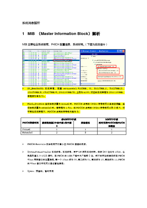
(下图为实测信令)➢DL_Bandwidth系统带宽,范围enumerate(1.4M(6RB,0),3M(15RB,1),5M(25RB,2),10M(50RB,3),15M(75RB,4),20M(100RB,5)),上图为n100,对应的系统带宽为20M(100RB,带宽索引号为5)。
➢Phich_Duration当该参数设置为normal时,PDCCH占用的OFDM符号数可以自适应调整;当该参数设置为extended时,若带宽为1.4M,则PDCCH占用的OFDM符号数可以取3或4,对于其他系统带宽下,PDCCH占用的符号数只能为3。
➢PHICH-Resource该参数用于计算小区PHICH信道的资源;➢SystemFrameNumber系统帧号。
系统帧号,用于UE获取系统时钟。
实际SFN位长为10bit,也就是取值从0-1023循环。
在PBCH的MIB广播中只广播前8位,剩下的两位根据该帧在PBCH 40ms周期窗口的位置确定,第一个10ms帧为00,第二帧为01,第三帧为10,第四帧为11。
PBCH 的40ms窗口手机可以通过盲检确定。
➢Spare:预留的,暂时未用2 SIB1 (System Information Block Type1)解析SIB1上主要传输评估UE能否接入小区的相关信息及其他系统消息的调度信息。
主要包括4部分:➢小区接入相关信息(cell Access Related Info)➢小区选择信息(cell Selection Info)➢调度信息(scheduling Info List)➢TDD配置信息(tdd-Config)SIB1消息解析(UE侧):RRC-MSG..msg....struBCCH-DL-SCH-Message......struBCCH-DL-SCH-Message........message..........c1............systemInformationBlockType1..............cellAccessRelatedInfo//小区接入相关信息................plmn-IdentityList//PLMN标识列表..................PLMN-IdentityInfo....................plmn-Identity ......................mcc//460 ........................MCC-MNC-Digit:0x4 (4) ........................MCC-MNC-Digit:0x6 (6) ........................MCC-MNC-Digit:0x0 (0) ......................mnc//00 ........................MCC-MNC-Digit:0x0 (0) ........................MCC-MNC-Digit:0x0 (0) ....................cellReservedForOperatorUse:notReserved (1) ................trackingAreaCode:11100(890C)//TAC跟踪区(890C)为16进制数,转换成十进制为35084,查TAC在该消息中可以查到,此条信元重要。
常用的电气专业英语词汇

induction machine 感应式电机horseshoe magnet 马蹄形磁铁magnetic field 磁场eddy current 涡流right-hand rule 右手定则left—hand rule 左手定则slip 转差率induction motor 感应电动机rotating magnetic field 旋转磁场winding 绕组stator 定子rotor 转子induced current 感生电流time-phase 时间相位exciting voltage 励磁电压solt 槽lamination 叠片laminated core 叠片铁芯short—circuiting ring 短路环squirrel cage 鼠笼rotor core 转子铁芯cast-aluminum rotor 铸铝转子bronze 青铜horsepower 马力random-wound 散绕insulation 绝缘ac motor 交流环电动机end ring 端环alloy 合金coil winding 线圈绕组form—wound 模绕performance characteristic 工作特性 frequency 频率revolutions per minute 转/分motoring 电动机驱动generating 发电per—unit value 标么值breakdown torque 极限转矩breakaway force 起步阻力overhauling 检修wind-driven generator 风动发电机revolutions per second 转/秒number of poles 极数speed-torque curve 转速力矩特性曲线plugging 反向制动synchronous speed 同步转速percentage 百分数locked—rotor torque 锁定转子转矩 full—load torque 满载转矩prime mover 原动机inrush current 涌流magnetizing reacance 磁化电抗line-to-neutral 线与中性点间的staor winding 定子绕组leakage reactance 漏磁电抗no—load 空载full load 满载Polyphase 多相(的)iron-loss 铁损complex impedance 复数阻抗rotor resistance 转子电阻leakage flux 漏磁通locked-rotor 锁定转子chopper circuit 斩波电路separately excited 他励的compounded 复励dc motor 直流电动机de machine 直流电机speed regulation 速度调节shunt 并励series 串励armature circuit 电枢电路optical fiber 光纤interoffice 局间的wave guide 波导波导管bandwidth 带宽light emitting diode 发光二极管silica 硅石二氧化硅regeneration 再生, 后反馈放大coaxial 共轴的,同轴的high—performance 高性能的carrier 载波mature 成熟的Single Side Band(SSB) 单边带coupling capacitor 结合电容propagate 传导传播modulator 调制器demodulator 解调器line trap 限波器shunt 分路器Amplitude Modulation(AM 调幅Frequency Shift Keying(FSK) 移频键控tuner 调谐器attenuate 衰减incident 入射的two—way configuration 二线制generator voltage 发电机电压dc generator 直流发电机polyphase rectifier 多相整流器boost 增压time constant 时间常数forward transfer function 正向传递函数error signal 误差信号regulator 调节器stabilizing transformer 稳定变压器time delay 延时direct axis transient time constant 直轴瞬变时间常数 transient response 瞬态响应solid state 固体buck 补偿operational calculus 算符演算gain 增益pole 极点feedback signal 反馈信号dynamic response 动态响应voltage control system 电压控制系统mismatch 失配error detector 误差检测器excitation system 励磁系统field current 励磁电流transistor 晶体管high-gain 高增益boost—buck 升压去磁feedback system 反馈系统reactive power 无功功率feedback loop 反馈回路automatic Voltage regulator(A VR)自动电压调整器reference Voltage 基准电压magnetic amplifier 磁放大器amplidyne 微场扩流发电机self-exciting 自励的limiter 限幅器manual control 手动控制block diagram 方框图linear zone 线性区potential transformer 电压互感器 stabilization network 稳定网络stabilizer 稳定器air—gap flux 气隙磁通saturation effect 饱和效应saturation curve 饱和曲线flux linkage 磁链per unit value 标么值shunt field 并励磁场magnetic circuit 磁路load-saturation curve 负载饱和曲线 air-gap line 气隙磁化线polyphase rectifier 多相整流器circuit components 电路元件circuit parameters 电路参数electrical device 电气设备electric energy 电能primary cell 原生电池energy converter 电能转换器conductor 导体heating appliance 电热器direct—current 直流time invariant 时不变的self—inductor 自感mutual-inductor 互感the dielectric 电介质storage battery 蓄电池e.m.f = electromotive force 电动势发电机generator励磁excitation励磁器excitor电压voltage电流current升压变压器step-up transformer母线bus变压器transformer空载损耗:no—load loss铁损:iron loss铜损:copper loss空载电流:no—load current有功损耗:reactive loss输电系统power transmission system 高压侧high side输电线transmission line高压:high voltage低压:low voltage中压:middle voltage功角稳定angle stability稳定stability电压稳定voltage stability暂态稳定transient stability电厂power plant能量输送power transfer交流AC直流DC电网power system落点drop point开关站switch station调节regulation高抗high voltage shunt reactor并列的:apposable裕度margin故障fault三相故障three phase fault分接头:tap切机generator triping高顶值high limited value静态static (state)动态dynamic (state)机端电压控制A VR电抗reactance电阻resistance功角power angle有功(功率)active power电容器:Capacitor电抗器:Reactor断路器:Breaker电动机:motor功率因数:power-factor定子:stator阻抗:impedance功角:power—angle电压等级:voltage grade有功负载: active load PLoad档位:tap position电阻:resistor电抗:reactance电导:conductance电纳:susceptance上限:upper limit下限:lower limit正序阻抗:positive sequence impedance负序阻抗:negative sequence impedance零序阻抗:zero sequence impedance无功(功率) reactive power功率因数power factor无功电流reactive current 斜率slope额定rating变比ratio参考值reference value电压互感器PT分接头tap仿真分析simulation analysis下降率droop rate传递函数transfer function框图block diagram受端receive-side同步synchronization保护断路器circuit breaker摇摆swing阻尼damping无刷直流电机:Brusless DC motor刀闸(隔离开关):Isolator机端generator terminal变电站transformer substation永磁同步电机:Permanent-magnet Synchronism Motor异步电机:Asynchronous Motor三绕组变压器:three-column transformer ThrClnTrans双绕组变压器:double—column transformer DblClmnTrans 固定串联电容补偿fixed series capacitor compensation双回同杆并架double—circuit lines on the same tower单机无穷大系统one machine - infinity bus system励磁电流:magnetizing current补偿度degree of compensationElectromagnetic fields 电磁场失去同步loss of synchronization装机容量installed capacity无功补偿reactive power compensation故障切除时间fault clearing time极限切除时间critical clearing time强行励磁reinforced excitation并联电容器:shunt capacitor〈下降特性droop characteristics线路补偿器LDC(line drop compensation)电机学Electrical Machinery自动控制理论Automatic Control Theory电磁场Electromagnetic Field微机原理Principle of Microcomputer电工学ElectrotechnicsPrinciple of circuits 电路原理Electrical Machinery 电机学电力系统稳态分析Steady-State Analysis of Power System电力系统暂态分析Transient-State Analysis of Power System电力系统继电保护原理Principle of Electrical System's Relay Protection 电力系统元件保护原理Protection Principle of Power System ’s Element 电力系统内部过电压Past V oltage within Power system模拟电子技术基础Basis of Analogue Electronic Technique数字电子技术Digital Electrical Technique电路原理实验Lab. of principle of circuits电气工程讲座Lectures on electrical power production电力电子基础Basic fundamentals of power electronics高电压工程High voltage engineering电子专题实践Topics on experimental project of electronics电气工程概论Introduction to electrical engineering电子电机集成系统electronic machine system电力传动与控制Electrical Drive and Control电力系统继电保护Power System Relaying Protectioninduction machine 感应式电机horseshoe magnet 马蹄形磁铁magnetic field 磁场eddy current 涡流right-hand rule 右手定则left—hand rule 左手定则slip 转差率induction motor 感应电动机rotating magnetic field 旋转磁场winding 绕组stator 定子rotor 转子induced current 感生电流time—phase 时间相位exciting voltage 励磁电压solt 槽lamination 叠片laminated core 叠片铁芯short—circuiting ring 短路环squirrel cage 鼠笼rotor core 转子铁芯cast—aluminum rotor 铸铝转子bronze 青铜horsepower 马力random-wound 散绕insulation 绝缘ac motor 交流环电动机end ring 端环alloy 合金coil winding 线圈绕组form-wound 模绕performance characteristic 工作特性frequency 频率revolutions per minute 转/分motoring 电动机驱动generating 发电per-unit value 标么值breakdown torque 极限转矩breakaway force 起步阻力overhauling 检修wind-driven generator 风动发电机revolutions per second 转/秒number of poles 极数speed—torque curve 转速力矩特性曲线 plugging 反向制动synchronous speed 同步转速percentage 百分数locked-rotor torque 锁定转子转矩full-load torque 满载转矩prime mover 原动机inrush current 涌流magnetizing reacance 磁化电抗line—to—neutral 线与中性点间的staor winding 定子绕组leakage reactance 漏磁电抗no-load 空载full load 满载Polyphase 多相(的)iron-loss 铁损complex impedance 复数阻抗rotor resistance 转子电阻leakage flux 漏磁通locked-rotor 锁定转子chopper circuit 斩波电路separately excited 他励的compounded 复励dc motor 直流电动机de machine 直流电机speed regulation 速度调节shunt 并励series 串励armature circuit 电枢电路optical fiber 光纤interoffice 局间的wave guide 波导波导管bandwidth 带宽light emitting diode 发光二极管silica 硅石二氧化硅regeneration 再生,后反馈放大coaxial 共轴的,同轴的high-performance 高性能的carrier 载波mature 成熟的Single Side Band(SSB)单边带coupling capacitor 结合电容propagate 传导传播modulator 调制器demodulator 解调器line trap 限波器shunt 分路器Amplitude Modulation(AM 调幅Frequency Shift Keying(FSK)移频键控 tuner 调谐器attenuate 衰减incident 入射的two-way configuration 二线制generator voltage 发电机电压dc generator 直流发电机polyphase rectifier 多相整流器boost 增压time constant 时间常数forward transfer function 正向传递函数error signal 误差信号regulator 调节器stabilizing transformer 稳定变压器time delay 延时direct axis transient time constant 直轴瞬变时间常数 transient response 瞬态响应solid state 固体buck 补偿operational calculus 算符演算gain 增益pole 极点feedback signal 反馈信号dynamic response 动态响应voltage control system 电压控制系统mismatch 失配error detector 误差检测器excitation system 励磁系统field current 励磁电流transistor 晶体管high-gain 高增益boost—buck 升压去磁feedback system 反馈系统reactive power 无功功率feedback loop 反馈回路automatic Voltage regulator(A VR)自动电压调整器reference Voltage 基准电压magnetic amplifier 磁放大器amplidyne 微场扩流发电机self-exciting 自励的limiter 限幅器manual control 手动控制block diagram 方框图linear zone 线性区potential transformer 电压互感器stabilization network 稳定网络stabilizer 稳定器air-gap flux 气隙磁通saturation effect 饱和效应saturation curve 饱和曲线flux linkage 磁链per unit value 标么值shunt field 并励磁场magnetic circuit 磁路load—saturation curve 负载饱和曲线 air—gap line 气隙磁化线polyphase rectifier 多相整流器circuit components 电路元件circuit parameters 电路参数electrical device 电气设备electric energy 电能primary cell 原生电池energy converter 电能转换器conductor 导体heating appliance 电热器direct-current 直流time invariant 时不变的self—inductor 自感mutual-inductor 互感the dielectric 电介质storage battery 蓄电池e。
damage control
上周末我们家庭聚会,表哥喝多了,说了一些对姑姑不敬的话,不久就传到了我姑姑的耳朵里。
几乎就在同时,表哥也意识到自己犯的错,赶紧去向姑姑赔罪,还特别送了鲜花。
他这一系列及时补救的做法让我想到了一句习惯用语,那就是: damage control。
我们都知道,damage这个词本身是破坏,损坏的意思,而control,控制。
连在一起,damage control,损害控制,意思就是采取措施将造成的损害降到最低。
就像上面的例子里,my cousin told my aunt that he was sorry and sent her flowers. It's damage control. 我表哥又道歉又送花,试图把损害降到最低。
下面的例子里,我们来听听看这个叫Drake的人怎么搞砸了他的晋升:例句-1:There were some doubts about whether Drake would be an effective Union president. Then, he made a racial remark in a speech at an assembly. At first, he ignored critics. Later, he tried to make a joke of it before deciding to offer a public apology. In the end, his attempts at damage control weren't successful. He lost out on the promotion.这段话是说:大家对于德雷克能不能成为一个好的工会主席很怀疑。
就在这时候,他在一次集会发言时,说了一句带有种族歧视色彩的话。
起初,他根本不理会别人的批评。
之后他试图用玩笑来掩盖这次错误,最后实在没办法才公开道歉。
Adobe Acrobat SDK 开发者指南说明书

This guide is governed by the Adobe Acrobat SDK License Agreement and may be used or copied only in accordance with the terms of this agreement. Except as permitted by any such agreement, no part of this guide may be reproduced, stored in a retrieval system, or transmitted, in any form or by any means, electronic, mechanical, recording, or otherwise, without the prior written permission of Adobe. Please note that the content in this guide is protected under copyright law.
电机及其控制专业英语词汇
电机及其控制专业英语词汇ac motor 交流电动机active (passive) circuit elements 有(无)源电路元件active component 有功分量active in respect to 相对….呈阻性admittance 导纳air-gap flux distribution 气隙磁通分布air-gap flux 气隙磁通air-gap line 气隙磁化线algebraic 代数的algorithmic 算法的alloy 合金ampere-turns 安匝(数)amplidyne 微场扩流发电机Amplitude Modulation (AM) 调幅armature circuit 电枢电路armature coil 电枢线圈armature m.m.f. wave 电枢磁势波attenuate 衰减automatic station 无人值守电站automatic Voltage regulator(AVR)自动电压调整器auxiliary motor 辅助电动机bandwidth 带宽base 基极bilateral circuit 双向电路bimotored 双马达的biphase 双相的bipolar junction transistor (BJT) 双极性晶体管block diagram 方框图boost 增加breakaway force 起步阻力breakdown torque 极限转矩bronze 青铜buck 补偿capacitance effect 电容效应carbon-filament lamp 碳丝灯泡carrier 载波Cartesian coordinates 笛卡儿坐标系cast-aluminum rotor 铸铝转子chopper circuit 斩波电路circuit branch 支路circuit components 电路元件circuit diagram 电路图circuit parameters 电路参数coaxial 共轴的,同轴的coil winding 线圈绕组coincide in phase with 与….同相collector 集电极converter 变流器commutation condition 换向状况commutator-brush combination 换向器-电刷总线complex impedance 复数阻抗complex number 复数compound generator 复励发电机compounded 复励conductance 电导conductor 导体corridor 通路coupling capacitor 耦合电容cumulatively compounded motor 积复励电动机dc generator 直流发电机dc motor 直流电动机de machine 直流电机demodulator 解调器differentiation 微分digital signal processing 数字信号处理digital signal processor (DSP) 数字信号处理器direct axis transient time constant 直轴瞬变时间常数direct axis 直轴direct-current 直流direct torque control (DTC) 直接转矩控制displacement current 位移电流dynamic response 动态响应dynamic-state operation 动态运行e.m.f = electromotive fore 电动势eddy current 涡流effective values 有效值effects of saturation 饱和效应electric energy 电能electrical device 电气设备electrode 电极电焊条electromagnetic torque 电磁转矩emitter 发射管放射器发射极end ring 端环energy converter 电能转换器epoch angle 初相角equivalent T – circuit T型等值电路error detector 误差检测器error signal 误差信号excitation system 励磁系统excited by 励磁exciting voltage 励磁电压external armature circuit 电枢外电路external characteristic 外特性feedback component 反馈元件feedback loop 反馈回路feedback signal 反馈信号feedback system 反馈系统feedforward signal 前馈信号feedforward system 前馈系统fidelity 保真度field coils 励磁线圈field current 励磁电流field effect transistor (FET) 场效应管field oriented control (FOC) 磁场定向控制field winding 磁场绕组励磁绕组flux linkage 磁链form-wound 模绕forward transfer function 正向传递函数Frequency Shift Keying(FSK) 移频键控frequency 频率full load 满载full-load torque 满载转矩full-order observer 全阶观测器gain 增益generating 发电generator voltage 发电机电压Geometrical position 几何位置harmonic 谐波的heating appliance 电热器high frequency 高频high-gain 高增益high-performance 高性能的horsepower (HP) 马力horseshoe magnet 马蹄形磁铁hydropower station 水电站ideal source 理想电源imaginary part 虚部impedance 阻抗incident 入射的induced current 感生电流induction generator 感应发电机induction machine 感应电机induction machine 感应式电机induction motor 感应电动机inductive component 感性(无功)分量infinite voltage gain 无穷大电压增益inrush current 涌流instantaneous electric power 瞬时电功率instantaneous mechanical power 瞬时机械功率insulation 绝缘integration 积分下限internal resistance 内阻interoffice 局间的inverse 倒数inverter 逆变器iron-loss 铁损isolation 隔离分离绝缘隔振laminated core 叠片铁芯lamination 叠片leakage current 漏电流leakage flux 漏磁通leakage reactance 漏磁电抗leakage 泄漏left-hand rule 左手定则light emitting diode 发光二极管lightning shielding 避雷limiter 限幅器line trap 限波器linear zone 线性区line-to-neutral 线与中性点间的load characteristic 负载特性load-saturation curve 负载饱和曲线locked-rotor torque 锁定转子转矩locked-rotor 锁定转子magnetic amplifier 磁放大器magnetic circuit 磁路magnetic field 磁场magnetic torque 电磁转矩magnetizing reacance 磁化电抗manual control 手动控制mature 成熟的mechanical rectifier 机械式整流器micro-controller 微控制器mid-frequency band 中频带mismatch 失配model reference adaptive control (MRAS) 模型参考自适应控制model reference adaptive system (MRAS) 模型参考自适应系统modulator 调制器modulus 模motoring 电动机驱动mutual flux 交互(主)磁通mutual-inductor 互感no-load 空载number of poles 极数observer 观测器operating condition 运行状态operational calculus 算符演算optical fiber 光纤Oscillation 振荡overhauling 检修P.D. = potential drop 电压降per unit value 标么值percentage 百分数performance characteristic 工作特性permanent magnet 永磁permanent magnet synchronous motor 永磁同步电机per-unit value 标么值phase displacement 相位差Phase Modulation (PM) 相位调制phase reversal 反相plugging 反向制动polarity 极性pole 极点polyphase rectifier 多相整流器polyphase rectifier 多相整流器Polyphase 多相(的)potential distribution 电位分布potential transformer 电压互感器power amplifier 功率放大器power frequency 工频primary cell 原生电池prime motor 原动机prime mover 原动机process of self – excitation 自励过程propagate 传导传播r.m.s values = root mean square values 均方根值random-wound 散绕reactive component 无功分量reactive in respect to 相对….呈感性reactive power 无功功率real part 实部rectifier 整流器reference Voltage 基准电压regeneration 再生, 后反馈放大regulator 调节器reluctance 磁阻retarding torque 制动转矩revolutions per minute 转/分revolutions per second 转/秒rheostat 变阻器right-hand rule 右手定则rotating commutator 旋转(整流子)换向器rotating magnetic field 旋转磁场rotor (stator) winding 转子(定子绕组)rotor core 转子铁芯rotor resistance 转子电阻rotor 转子salient poles 凸极saturation curve 饱和曲线saturation effect 饱和效应self–excitation process 自励过程self excited 自励self-bias resistor 自偏置电阻self-exciting 自励的self-inductor 自感self-sensing 位置自检测sensorless 无传感器的separately excited 他励的series excited 串励series 串励shaft 轴shaft-less 无轴承的short-circuiting ring 短路环shunt displacement current 旁路位移电流shunt excited 并励shunt field 并励磁场shunt 并励shunt 分路器signal amplifier 小信号放大器silica 硅石二氧化硅Single Side Band(SSB) 单边带sinusoidal – density wave 正弦磁密度sinusoidal time function 正弦时间函数slip 转差率solid state 固体solt 槽spatial waveform 空间波形spectral 频谱的spectrum 频谱speed regulation 速度调节speed-torque characteristic 速度转矩特性speed-torque curve 转速力矩特性曲线squirrel cage 鼠笼stabilization network 稳定网络stabilizer 稳定器stabilizing transformer 稳定变压器staor winding 定子绕组stator 定子steady–state condition 稳态条件steady direct current 恒稳直流电storage battery 蓄电池summing circuit 总和线路反馈系统中的比较环节synchronous condenser 同步进相(调相)机synchronous generator 同步发电机synchronous reactance 同步电抗synchronous reluctance motor (SRM) 同步磁阻电机synchronous speed 同步转速technical specifications 技术条件terminal voltage 端电压the dielectric 电介质time constant 时间常数time delay 延时time invariant 时不变的time-phase 时间相位transformer 变压器transient response 瞬态响应transistor 晶体管triangular symbol 三角符号trigonometric transformations 瞬时值tuner 调谐器turns ratio 变比匝比two-way configuration 二线制unidirectional current 单方向性电流variable frequency drive (VFD) 变频器vector equation 矢量方程vector control 矢量控制voltage across the terminals 端电压voltage control system 电压控制系统volt-ampere characteristics 伏安特性waveguide 波导波导管wind-driven generator 风动发电机winding loss 绕组(铜)损耗winding 绕组。
英汉词典

接合座 自适应总线-digital data highway to which(almost) any number of inputs 地址-electronic code identifying each part of computer memory,each address bit or information unit being routed to different address adhesion 粘接 adhesive tape 粘胶带 adjacent to 邻近的 可调水平安定面-horizontal stabilizer of an airplane which may be adjustable stabilizer adjusted in flight to trim the airplane for hands-off mode in flight admittance 导纳-in AC circui,reciprocal of impedance advance drawing 图纸先行更改通知 change notice(ADCN) advanced 先进的-new sophisticated and typifying latest technology advanced switch 步进电门 adverse effect 不利影响;严重后果 advisory circular(AC) 咨询通报 advisory Message 咨询信息 aerodynamic 空气动力的 aerodynamic smoother 空气动力平滑胶 aeroelastic torsion 气动弹性扭曲 aeronautical 航空的 aerosol 烟雾,浮质-colloid of finely divided solid or liquid disperesed in aft looking forward 从后向前看 afterbody drag 后体阻力 afterburner 加力燃烧室 尾喷管喷火-sometimes called torching,a condition resulting from afterfiring unburrnt fuel being ignited in the exhaust nozzle age-hardening 时效,硬化 ageing=aging 时效处理 aging 老龄的 agent 试剂 aileron 付翼 aileron authority 付翼效能 付翼传动力限制器-electro-mechanical device for limiting the control aileron force limiter wheel movement by the autopilot during autopilot operation aileron programmer 付翼程序器-convert central lateral control actuator motion to control air bleed valve 放气活门 减速板;阻力板-a plate or series of plates that may be projected into air brake airport's slipstream to provide turbulence and drag to slow the air carrier 航空营运者-any company which provides commercial air transportation air conditioning 空调 空气循环机;涡轮冷却器-a compressor & turbine on a common shaft for air cycle machine cooling air in an air conditioning system 大气数据计算机-one which produces air data air data computer information(altitude,airspeed ect) based on pressure and temperature 中断飞行-a change from original flight plan due to a known or air interruption suspected malfunction&/ defect during flight air lock 气锁,气塞-a trapped pocket of air that blocks the flow of fluid 空气封严件;气密封圈;气封严-usually thin rotating or staionary rims air seal designed to act as air DAMS to reduce airflow leakage air ground 起落架位置传感器;空地传感器-an electrical device operated by the sensor landing gear for transmitting airport position for systems operation air tapping 抽气管座 空中返航-return of airplane to airplane of origin as a result of air turnback malfunction or suspected defect of any item on airplane airborne 空中飞行的;机载的
ControlinRobotics:控制机器人

Mark W. Spong and Masayuki FujitaIntroductionThe interplay between robotics and control theory has a rich history extending back over half a century. We begin this section of the report by briefly reviewing the history of this interplay, focusing on fundamentals—how control theory has enabled solutions to fundamental problems in robotics and how problems in robotics have motivated the development of new control theory. We focus primarily on the early years, as the importance of new results often takes considerable time to be fully appreciated and to have an impact on practical applications. Progress in robotics has been especially rapid in the last decade or two, and the future continues to look bright.Robotics was dominated early on by the machine tool industry. As such, the early philosophy in the design of robots was to design mechanisms to be as stiff as possible with each axis (joint) controlled independently as a single-input/single-output (SISO) linear system. Point-to-point control enabled simple tasks such as materials transfer and spot welding. Continuous-path tracking enabled more complex tasks such as arc welding and spray painting. Sensing of the external environment was limited or nonexistent.Consideration of more advanced tasks such as assembly required regulation of contact forces and moments. Higher speed operation and higher payload-to-weight ratios required an increased understanding of the complex, interconnected nonlinear dynamics of robots. This requirement motivated the development of new theoretical results in nonlinear, robust, and adaptive control, which in turn enabled more sophisticated applications.Today, robot control systems are highly advanced with integrated force and vision systems. Mobile robots, underwater and flying robots, robot networks, surgical robots, and others are playing increasing roles in society. Robots are also ubiquitous as educational tools in K-12 and college freshman experience courses.The Early YearsThe first industrial robot in the United States was the Unimate, which was installed in a General Motors plant in 1961 and used to move die castings from an assembly line and to weld these parts on auto bodies (Fig. 1). Full-scale production began in 1966. Another company with early robot products was Cincinnati Milacron, with companies in Japan and Europe also entering the market in the 1970s. Prior to the 1980s, robotics continued to be focused on manipulator arms and simple factory automation tasks: materials handling, welding, and painting.From a control technology standpoint, the primary barriers to progress were the high cost of computation, a lack of good sensors, and a lack of fundamental understanding of robot dynamics. Given these barriers, it is not surprising that two factors were the primary drivers in the advancement of robot control in these early days. First, with the realization of the close connection between robot performance and automatic control, a community developed that focused on increasing fundamental understanding of dynamics, architecture, and system-level design. In retrospect, we can see that thiswork had some significant limitations:control schemes were mostly based onapproximate linear models and did notexploit knowledge of the naturaldynamics of the robot, vision and forcecontrol were not well integrated intothe overall motion control architecture,and mechanical design and controlsystem design were separate.The second factor was exogenous toboth the controls and roboticscommunities, namely, Moore’s Law.The increasing speed and decreasingcost of computation have been keyenablers for the development andimplementation of advanced, sensor-based control. for robots, and creative new ideas —Control of ManipulatorsBeginning in the mid-1980s, robot manipulatorsbecame a “standard” control application, and the synergies were widely recognized and exploited in research. The earlier research on computed torque and inverse dynamics control [1], for example,helped motivate the differential geometric method of feedback linearization that has been applied to numerous practical problems within and outside of robotics [2]. For fully actuated rigid manipulators, the feedback linearization method was put on a firmtheoretical foundation and shown to be equivalent to the inverse dynamics method [3]. The firstnontrivial application of the feedback linearizationimmediately raised. Standard Hnature of the uncertainty. A solution for the special case of second-order systems, using the small-gain theorem, was worked out in [5], and the general case was presented in [6], which subsequently led to a new area of control now known as L1-optimal control—a prime example of a robotics control contribution leading to new control theory. Several other methods of robust control, such as sliding modes and Lyapunov methods, have also been applied to the robust control problem for robot manipulators.The mid-1980s were also a time of development in adaptive control, and again the connection with robotics was pursued. The fundamental breakthrough in the adaptive control of rigid manipulators was made by Slotine and Li [7]. The key to the solution of the adaptive control problem was the recognition of two important properties of Lagrangian dynamical systems: linearity in the inertia parameters and the skew-symmetry property of the robot inertia matrix [8].Subsequently, the skew symmetry property was recognized as being related to the fundamental property of passivity. The term passivity-based control was introduced in the context of adaptive control of manipulators [9]. Passivity-based control has now become an important design method for a wide range of control engineering applications. Array independent of the time delay.A state-of-the-art teleoperated robot is theDa Vinci surgical system from IntuitiveSurgical, which integrates advances inmicromanipulators, miniature cameras, and amaster-slave control system to enable asurgeon to operate on a patient via a consolewith a 3-D video feed and foot and handcontrols. However, neither force feedbacknor remote operations are supported as yet;the surgeon’s console is typically by thepatient’s side.Mobile Robotsby Brockett’ssystems do not exist [12]. Brockett’smethods , including hybrid switching control and time-varying approaches to stabilization of nonholonomic systems.Mobile robots are now regularly used in many applications. One prominent application is aiding disaster recovery efforts in mines and after earthquakes. Military uses, such as for roadside bomb detection, form another broad category. Recently, products have been developed for consumer applications, such as the Roomba® and other robots from iRobot. Finally, wheeled mobile robots are exploring Mars and are poised to return to the moon.Market Sizes and InvestmentThe robotics industry was slow getting started. Unimation did not show its first profit until 1975, almost a decade after it began full-scale production of its pioneering Unimate robot. Today, the Robotic Industries Association estimates that more than one million robots are in use worldwide; Japan has the largest deployment, with the United States having the second largest.According to one recent market research report from Electronics.ca Publications, the global market for robotics was worth $17.3 billion in 2008 and is projected to increase to $21.4 billion in 2014, a compound annual growth rate (CAGR) of 4.0%. The largest segment of the market is industrial applications, worth $11.5 billion. Industrial robots, with their heavy reliance on the automotive industry, were especially hard hit with the recent global recession—2009 shipments were down 50% from year-ago levels, according to the Robotic Industry Association. Projected growth is lower for this segment than for professional service (market size of $3.3 billion in 2008) and military ($917 million) applications. Domestic services, security, and space applications constitute smaller segments, although the huge success of the Roomba floor-cleaning robot has demonstrated the enormous potential of consumer robotics.Research ChallengesUnderactuationUnderactuated robots have fewer control inputs than degrees of freedom and are a natural progression from flexible-joint and flexible-link robots. Underactuation leads naturally to a consideration of partial or output feedback linearization as opposed to full-state feedback linearization. Consideration of normal forms and zero dynamics is important in this context [13]. Energy/passivity methods are fundamental for the control of underactuated systems.Visual Servo Control and Force ControlThe idea of using imaging or video sensors for robot control is not new; it predates the availability of low-cost, high-quality digital cameras and advances in computational platforms enabling real-time processing of digital video signals. These latter developments have significantly increased interest in the topic.Visual servo control has traditionally used two methodologies, namely, position-based control and image-based control [14]. Position-based control uses vision to estimate the absolute position of the robot and uses the computed position error in the control algorithm. Image-based control, on the other hand, is based on computing the error directly in the image plane of the camera and avoids calculation of the robot position; thus, it is less sensitive to kinematic and calibration errors. Recently, bothposition-based and image-based methods have been incorporated into hybrid switching control strategies in order to take advantage of the strengths and avoid the weaknesses of both approaches. Similar to vision-based control, force control in robotics has also traditionally been divided into two fundamental strategies, in this case, called hybrid position/force control and impedance control, respectively. Hybrid position/force control is based on the observation that one cannot simultaneously control both the position of a robot and the force it imparts to the environment. Thus, the task at hand can be decomposed into “directions” along which either position or force (but not both) is controlled. Conversely, impedance control does not attempt to control or track positions and forces. Rather the “mechanical impedance,” which is the suitably defined Laplace transform of the velocity/force ratio, is the quantity to be controlled.LocomotionThe development of legged robots is motivated by the fact that wheeled robots are not useful in rough terrain or in built structures. The number of legs involved is a free parameter in this research, with robots with as few as one (hopping robots) and as many as eight having been developed by multiple research groups. Bipedal robots are a particularly popular category, both for the anatomical similarity with their creators and because of the research challenges posed by their dynamic instability. An understanding of the dynamics and control of bipedal locomotion is also useful for the development ofprosthetic and orthotic devices to aid humans with disabilities or missing limbs.Readers who have seen videos of Honda’s Asimov robots (Fig. 2) (readers who have not can check YouTube) or other humanoid robots may think that bipedal robots are “for real” now. The accomplishments of this research are indeed impressive. These robots can walk up and down ramps and stairs, counteract pushes and pulls, change gait, roll carts, play table tennis, and perform other functions. But the transition from research laboratory to commercial practice has not been made as yet. In particular, challenges remain for control engineers in the locomotion aspects specifically.Control of bipedal locomotion requires consideration of three difficult issues: hybrid nonlinear dynamics, unilateral constraints, and underactuation. The hybrid nature of the control problem results from impacts of the foot with the ground, which introduce discrete transitions between phases of continuous dynamic motion. Unilateral constraints arise from the fact that the foot can push but not pull on the ground and so the foot/ground reaction forces cannot change sign. Underactuation results again from the(Credit: Gnsin) Figure 2. Honda’s Asimov humanoid robot at Expo 2005 in Aichi, Japan.foot/ground interaction; there is no actuation torque between the foot and the ground. All these difficult issues require advanced methods of control to address them adequately. Energy/passivity methods, geometric nonlinear control, partial feedback linearization, zero dynamics, and hybrid control theory are all fundamental tools for designing rigorous control algorithms for walking [15], [16].Multi-Agent Systems and Networked ControlNetworked control systems and multi-agent systems are important recent application areas for robotics (Fig. 3). Synchronization, coordination, cooperative manipulation, flocking, and swarming combine graph theoretic methods with nonlinear control.The eme rging “hot topic” of cyber-physical systems is also closely related to networked control. Cyber-physical systems will get their functionality through massive networking. Sensors, actuators, processors, databases, and control software will work together without the need to be collocated.Figure 3. Coordinated robots competing in the international RoboCup soccercompetition in 2003. The Cornell team, led by controls researcherRaffaello D’Andrea, won the competition in 1999, 2000, 2002, and 2003.ConclusionsRobotics today is a much richer field than even a decade or two ago, with far-ranging applications. Developments in miniaturization, in new sensors, and in increasing processing power have all openedMeasurement and Control, vol. 109, pp. 310-319, Dec. 1987.[5] M.W. Spong and M. Vidyasagar. “Robust linear compensator design for nonlinear r obotic Control,” IEEE Journal of Robotics and Automation, vol. RA 3, no. 4, pp. 345-350, Aug. 1987.[6] M. Vidyasagar. “Optimal rejection of persistent bounded disturbances,” IEEE Trans. Auto. Control, vol. AC-31, no. 6, pp. 527-534, June 1986.[7] J.-J.E. Slotine and W. Li. “On the adaptive control of robot m anipulators,” Int. J. Robotics Res., vol. 6, no. 3, pp. 147-157, Fall 1987.[8] D. Koditschek. “Natural motion of robot a rms,” in Proc. IEEE Conference on Decision and Control, Las Vegas, 1984.[9] R. Ortega and M.W. Spong. “Adaptive control of robot manipulators: A tut orial,” Automatica, vol. 25, no. 6, pp. 877-888, 1989.[10] R. Anderson and M. W. Spong. “Bilateral teleoperation with time d elay,” IEEE Trans. Aut. Cont., vol. 34, no. 5, pp. 494-501, May 1989.[11] G. Niemeyer and J.-J.E. Slotine. “Stable adaptive teleoperation,” IEEE Journal of Oceanographic Engineering, vol. 16, no. 1, pp. 152–162, 1991.[12] R. W. Brockett. “Asymptotic stability and feedback stabilization,” in Differential Geometric Control Theory, R.W. Brockett, R.S. Millman, and H. J. Sussmann, eds. Boston-Basel-Stuttgart: Birkhauser, 1983, pp. 181-191.[13] A. Isidori and C.I. Byrnes. “Output regulation of nonlinear systems,”IEEE Transactions on Automatic Control, vol. 35, no. 2, pp. 131-140, 1990.[14] S. A. Hutchinson, G.D. Hager, and P.I. Corke. “A tutorial on visual servo c ontrol,” IEEE Transactions on Robotics and Automation, vol. 12, no. 5, pp. 651-670, 1996.[15] E.R. Westervelt, J.W. Grizzle, and D.E. Koditschek. “Hybrid zero dynamics of planar biped w alkers,” IEEE Transactions on Automatic Control, vol. 48, no. 1, pp. 42-56, 2003.[16] M.W. Spong and F. Bullo. “Controlled symmetries and passive w alking,” IEEE Transactions on Automatic Control, vol. 50, no. 7, pp 1025-1031, 2005.Related ContentThe Impact of Control Technology report also includes more than 40 flyers describing specific “success stories” and “grand challenges” in control engineering and science, covering a variety of application domains. The ones below are closely related to the topic of this section.Success Stories∙Dynamic Positioning System for Marine Vessels –S.S. Ge, C.Y. Sang, and B.V.E. How∙Mobile-Robot-Enabled Smart Warehouses –R. D´AndreaGrand Challenges∙Control Challenges in High-Speed Atomic Force Microscopy –S.O.R. Moheimani∙Control for Offshore Oil and Gas Platforms –S.S. Ge, C.Y. Sang, and B.V.E. HowThese flyers—and all other report content—are available at /main/IoCT-report.。
诺瓦科技无线LED控制卡LED多媒体播放器TB2详细参数说明书

Trademark
is a trademark of Xi’an NovaStar Tech Co., Ltd.
Statement
You are welcome to use the product of Xi’an NovaStar Tech Co., Ltd. (hereinafter referred to as NovaStar). This document is intended to help you understand and use the product. For accuracy and reliability, NovaStar may make improvements and/or changes to this document at any time and without notice. If you experience any problems in use or have any suggestions, please contact us via contact info given in document. We will do our best to solve any issues, as well as evaluate and implement any suggestions.
4 Software Structure ........................................................................................................................ 8
4.1 System Software .......................................................................................................................................... 8 4.2 Related Configuration Software ................................................................................................................... 8
ros_control 用法
ros_control 用法Ros_control is a crucial component in the Robot Operating System (ROS) that allows for the control of robot joints and interfaces. It provides a set of tools and capabilities for controlling robotic systems, including hardware interfaces, controllers, and real-time communication. The use of ros_control is essential for developing and implementing advanced robot control strategies, such as trajectory tracking, force control, and impedance control. It enables the integration of various sensors and actuators with the ROS ecosystem, making it easier to build and control complex robotic systems.One of the key aspects of ros_control is itsflexibility and extensibility. It provides a modular framework for implementing different types of controllers, such as PID controllers, adaptive controllers, and model-based controllers. This allows developers to choose the most suitable control strategy for their specific application and easily switch between different controllersas needed. Additionally, ros_control supports various hardware interfaces, including joint position, velocity, and effort control, as well as custom hardware interfaces for specialized robotic systems.Another important feature of ros_control is its real-time capabilities. It is designed to work in real-time environments, ensuring that control commands are executed with minimal delay and jitter. This is essential for applications that require precise and responsive control, such as robotic manipulation, mobile robotics, and legged locomotion. Ros_control leverages real-time operating system (RTOS) capabilities and hardware abstraction layers to achieve low-latency and deterministic control performance.From a practical perspective, ros_control simplifies the development and deployment of robot control software. It provides a standardized interface for interacting with robot hardware, making it easier to integrate different robotic components and systems. This simplifies the development process and reduces the time and effortrequired to build and test robot control algorithms. Additionally, ros_control integrates seamlessly with other ROS packages, such as robot_description for robot modeling and rviz for visualization, making it easier to develop and debug robot control software.In addition to its technical capabilities, ros_control has a strong community and ecosystem that provides support, documentation, and resources for developers. The ROS community is active and vibrant, with a large number of users and contributors who are willing to help and share their knowledge. This makes it easier for developers to learn ros_control and get assistance with any issues or challenges they may encounter. Furthermore, there are many open-source robot platforms and simulation environmentsthat support ros_control, making it easier to test and validate control algorithms in a virtual environment before deploying them on real hardware.Overall, ros_control is an essential tool for developing and implementing robot control software. Its flexibility, real-time capabilities, and integration withROS make it a powerful and versatile platform for controlling a wide range of robotic systems. By leveraging ros_control, developers can build advanced and reliable robot control solutions that meet the requirements of modern robotics applications. Whether it's for industrial automation, service robotics, or research and education, ros_control provides the necessary tools and capabilities to drive innovation and progress in the field of robotics.。
控制冲动 英语同义表达
控制冲动英语同义表达The Importance of Impulse Control in Daily Life.Impulse control, often referred to as self-control or self-regulation, is a crucial skill that individuals need to possess in order to function effectively in society. The ability to restrain one's impulses is what separates impulsive behavior from purposeful, considered actions. In this article, we will explore the concept of impulse control, its importance in various aspects of life, and strategies to cultivate this valuable skill.1. Defining Impulse Control.Impulse control can be defined as the ability to override or resist the urge to act impulsively in response to a stimulus. Impulses are spontaneous urges or desires that are typically driven by emotions, such as anger, happiness, or desire. While impulses can sometimes lead to positive outcomes, such as a spur-of-the-moment act ofkindness, they can also result in negative consequences, such as making rash decisions or acting out in inappropriate ways.2. The Importance of Impulse Control.Impulse control is essential for several reasons. Here are some of the key areas where impulse control plays a pivotal role:a. Emotional Regulation: Impulse control helps individuals regulate their emotions effectively. By resisting the urge to act impulsively, one can avoid behaviors that might escalate emotional reactions or lead to conflict.b. Decision-Making: Impulse control improves decision-making by allowing individuals to consider the consequences of their actions before acting. This leads to more thoughtful and well-considered decisions that are less likely to have negative outcomes.c. Social Relationships: Impulse control is crucial for maintaining healthy social relationships. By restraining oneself from acting impulsively, individuals can avoid hurting others' feelings or damaging relationships through inappropriate behavior.d. Professional Success: In the workplace, impulse control is essential for maintaining professionalism and avoiding conflicts. Employees who can control their impulses are more likely to make positive contributions to the workplace and achieve success in their careers.e. Mental Health: Impulse control is also crucial for maintaining mental health. Individuals who have difficulty controlling their impulses may be more prone to anxiety, depression, and other mental health issues.3. Strategies for Cultivating Impulse Control.Impulse control is a skill that can be cultivated through practice and effort. Here are some strategies that can help individuals improve their impulse control:a. Mindfulness: Practicing mindfulness, or being awareof one's thoughts, feelings, and surroundings, can help individuals identify impulses before they lead to impulsive behavior. By pausing and reflecting on one's actions, individuals can gain a better understanding of their urges and choose more appropriate responses.b. Meditation: Meditation is a powerful tool for developing impulse control. Through regular meditation practice, individuals can learn to calm their minds and focus their attention, reducing the likelihood of acting impulsively.c. Goal Setting: Having clear goals and plans can help individuals stay on track and avoid being swayed by impulsive urges. By setting specific, measurable goals and creating a plan to achieve them, individuals can stay focused and resist the urge to act impulsively.d. Delayed Gratification: Practicing delayed gratification, or the ability to wait for a desired outcome,can help individuals develop impulse control. By resisting the urge to act immediately and instead waiting for a more appropriate time, individuals can cultivate patience and self-control.e. Support System: Having a support system of friends, family, or professionals can provide individuals with the encouragement and support they need to work on improving their impulse control. By sharing their struggles and successes, individuals can gain valuable feedback and insights that can help them on their journey.In conclusion, impulse control is a crucial skill that individuals need to possess in order to function effectively in society. By understanding the importance of impulse control and implementing strategies to cultivate this skill, individuals can improve their emotional regulation, decision-making, social relationships, professional success, and mental health. With practice and effort, impulse control can become a powerful tool for achieving personal growth and success.。
下肢康复机器人及其交互控制方法
第40卷第11期自动化学报Vol.40,No.11 2014年11月ACTA AUTOMATICA SINICA November,2014下肢康复机器人及其交互控制方法胡进1侯增广1陈翼雄1张峰1,2王卫群1摘要瘫痪病人的数量与日俱增,其康复训练通常是一个长期的过程.相对于传统的理疗,使用机器人辅助康复训练能够提高效率,降低成本,减少理疗师的人员和体力消耗,因此节省了康复医疗资源,并且可以完成更加多样的主被动训练策略,从而提高了康复效果.根据患者进行康复运动时的身体姿态,下肢康复机器人可分以下4类:坐卧式机器人、直立式机器人、辅助起立式机器人和多体位式机器人,坐卧式又细分为末端式和外骨骼式,直立式进一步划分为悬吊减重(Suspending body weight support,sBWS)式步态训练机器人和独立可穿戴式机器人.由于下肢康复机器人是与运动功能受损的患肢相互作用,为了给患者创造一个安全、舒适、自然的训练环境,机器人和患者之间的交互控制不可或缺.根据获取运动意图时所使用的传感器信号,交互控制可以基本分为两类:1)基于力信号的交互控制;2)基于生物医学信号的交互控制.在基于力信号的交互控制中,力位混合控制和阻抗控制是最为常用的两种方法;而在基于生物医学信号的交互控制中,表面肌电(Surface electromyogram,sEMG)和脑电(Electroencephalogram,EEG)最常被用于运动意图的推断.关键词下肢康复机器人,研究现状,交互控制,生物医学信号,发展趋势引用格式胡进,侯增广,陈翼雄,张峰,王卫群.下肢康复机器人及其交互控制方法.自动化学报,2014,40(11):2377−2390 DOI10.3724/SP.J.1004.2014.02377Lower Limb Rehabilitation Robots and Interactive Control MethodsHU Jin1HOU Zeng-Guang1CHEN Yi-Xiong1ZHANG Feng1,2WANG Wei-Qun1Abstract The number of paralytic sufferers is currently growing huge and the rehabilitation for them is usually a long-time pared to the traditional physiotherapy,rehabilitation with the assistance of robots can reduce the cost and time,and less labor intensity is required.Moreover,various training strategies are provided by robots,so that rehabilitation effect can be improved.Lower limb rehabilitation robots are categorized into horizontal exercisers, vertical locomotors,sit-to-stand aids and multi-orientation hybrids,according to the posture of patient during therapy. Horizontal exercisers are subcategorized into end effectors and exoskeletons,and vertical locomotors are further grouped as suspending body weight support(sBWS)based gait trainers and stand-alone wearables.Interactive control between mechanism and patient is required to create a secure,comfortable and natural training environment for paralytic patients. According to the signals employed to deduce the movement intention of patients,interactive control methods are classified into force-based control and biomedical-signal-based control.Two approaches that are in particular worth mentioning for force-based interactive control are hybrid force-position control and impedance control.Surface electromyogram(sEMG) and electroencephalogram(EEG)are two mostly used signals for biomedical-signal-based control.Key words Lower limb rehabilitation robot,state of the art,interactive control,biomedical signals,future development Citation Hu Jin,Hou Zeng-Guang,Chen Yi-Xiong,Zhang Feng,Wang Wei-Qun.Lower limb rehabilitation robots and interactive control methods.Acta Automatica Sinica,2014,40(11):2377−2390中风和脊髓损伤是导致下肢运动功能障碍的两大主要原因.中风又称脑卒中,是一种急性的脑血管收稿日期2013-07-05录用日期2014-07-18Manuscript received July5,2013;accepted July18,2014国家自然科学基金项目(61225017,61175076),国家国际科技合作专项项目(2011DFG13390)资助Supported by National Natural Science Foundation of China (61225017,61175076)and the International Science&Technol-ogy Cooperation Project of China(2011DFG13390)1.中国科学院自动化研究所复杂系统管理与控制国家重点实验室北京1001902.中国科学院自动化研究所精密感知与控制研究中心北京1001901.State Key Laboratory of Management and Control for Com-plex Systems,Institute of Automation,Chinese Academy of Sci-ences,Beijing1001902.Research Center of Precision Sensing and Control,Institute of Automation,Chinese Academy of Sci-ences,Beijing100190疾病,其发病突然并且难以预测.它能够造成永久性的大脑神经损伤,致残率一直居高不下,幸存的患者常常会遭受后遗症的折磨,偏瘫就是其中最为常见一种.根据卫生部的统计数据显示,2011年,在我国40岁以上的人群中,新发缺血性脑卒中的人数约为133.4万,标化发病率约为230/10万人,并且正在以每年将近9%的速率在上升;截至到2012年底,我国脑卒中标化患病率约为1.82%,40岁以上的罹患人群高达1036万人,其中65岁以下人群约占50%,年轻化趋势严重[1].在幸存的脑卒中患者中,大约有75%的人不同程度地丧失了劳动或生活自理能力,其中40%左右的患者重度致残[2].目前,脑卒中已经成为我国60岁以上人群残疾的第2378自动化学报40卷一位原因[1].脊髓损伤则通常是由严重的脊柱外伤造成,各种意外事故都有可能导致脊髓损伤的发生.和中风一样,脊髓损伤有着很高的致残率,可能导致截瘫、四肢瘫等病症,严重妨碍了患者的日常生活活动.根据2006年的统计数据显示,全世界脊髓损伤的患病率为233∼755/100万,每年的发病率为10.4∼83/100万[3].中国康复研究中心和北京卫生信息中心公布的北京市脊髓损伤发病率调查报告显示,20世纪80年代末北京市脊髓损伤发病率仅为6.8/100万,而2002年则达到了60/100万[4],在14年时间里上升了7.82倍.由于脑血管疾病的高发病率和频繁发生的各种意外事故,中国的瘫痪患者数量与日俱增.根据第二次全国残疾人抽样调查[5]和第六次全国人口普查的数据[6]推算,2013年中国的肢体残疾者数量达到了3700万,占全国人口的2.65%,平均年增长率为6.30%.然而,与庞大的康复医疗需求相矛盾的是,可用的康复医疗资源相对有限.中国现阶段需要康复治疗师约11.47万人,人才缺口达10.09万人,开设康复医学科的综合医院仅有3288家,占全国综合医院总数的24.6%,其中只有一半开设康复病区[7]. 2002年的统计数据显示,只有1.5%的脊髓损伤患者能够接受康复治疗[8].针对瘫痪患者,在经过诸如外科手术等急性期的临床处理后,康复成为主要的一种治疗手段,它能够帮助患肢恢复运动功能,重新学习日常生活活动,从而尽最大可能地帮助患者回归正常生活.这通常都是一个相当长期的持续过程,有时甚至可能贯穿患者一生的时间.在传统的康复治疗手段中,患者的运动训练主要依靠理疗师的手动辅助,一般比较耗时,成本也相对较高;并且由于主动训练难以手动实现,所以患肢的运动基本上都是被动的,训练策略比较单一;此外,在训练过程中,患肢的运动轨迹以及施加在患肢上的力度往往难以保持良好的一致性.而使用康复机器人辅助患者运动训练则可以提高效率、降低成本,并能够实现多种不同的主被动训练策略,同时机器人的运动轨迹和施加在患肢上的力度具备良好的一致性.除了上面提到的不足,传统的训练手段还很消耗患者和理疗师的体力,尤其是下肢的康复运动,因此,患者常常无法获得足够频次和强度的运动训练,每次的训练也都无法持续足够长的时间.康复机器人则可以减轻治疗过程中患者和理疗师体力负担,从而提高了康复训练的频率和持续时间.以常见的减重步行训练为例,在传统的方法中,至少需要三个理疗师才能完成一次步态训练,其中一位负责支撑患者的体重,剩下的两位各负责患者一条下肢的运动.然而,悬吊减重式步态训练机器人能够实现与传统方法几乎相同的康复效果,但却大大地降低了所需的体力付出,整个步态训练过程只需要一个理疗师进行少量的协助和在旁监护即可.显然,步态机器人可以显著地增加患者的练习次数以及每次持续的时间.因此,相对于传统理疗,使用机器人辅助瘫痪患者进行康复显然是一种更加优越的训练方法.本文系统地回顾了下肢康复机器人的发展现状以及机器人和患者之间的交互控制方法.文章后面的几个章节安排如下:在第1节中将下肢康复机器人分为了4类,分别是坐卧式机器人、直立式机器人、辅助起立式机器人和多体位式机器人,文中对每类设备的功能特点和适用范围进行了总结.此外,针对每类下肢康复机器人,选择了目前有代表性的设备,概述了它们的机械结构、训练策略和临床实验,并分析了每款机器人的优缺点.第2节综述了机器人与患者之间的交互控制方法,详细介绍了基于力信号的交互控制以及基于生物医学信号的交互控制.最后一节在总结全文的基础上,讨论了下肢康复机器人未来的发展趋势.1下肢康复机器人目前,关于下肢康复机器人的概念,还没有一个标准通用的叙述.但是根据普遍公认的理解,下肢康复机器人就是能够辅助下肢运动功能受损的瘫痪患者自动或半自动完成康复训练的机电一体化设备.它主要通过对患肢实施运动训练和功能性电刺激的方法,对患者受损的中枢神经形成反馈,刺激损伤神经的再生或者未损伤神经对损伤功能的代偿,以达到神经康复的目的.在过去十几年的时间里,由于医疗市场的广泛需求,以及机器人技术的快速发展,大量的研究机构和公司开始对下肢康复机器人进行开发研究,其中的一些研究成果已经成功地产品化.根据患者在康复训练中的身体姿态,下肢康复机器人大致分为以下4大类:坐卧式机器人、直立式机器人、辅助起立式机器人和多体位式机器人.1.1坐卧式机器人坐卧式下肢康复机器人最大的优势在于,在运动训练过程中,患者处于坐立、斜躺或平躺的姿态,无需下肢为身体提供支撑,因此它适用于运动功能完全丧失的瘫痪患者.但是对于已经能够部分自主控制下肢肌肉收缩的患者而言,坐卧的身体姿势不利于患肢步行功能的恢复.根据机构与患肢之间相互作用方式,坐卧式下肢康复机器人可以进一步细分为末端式和外骨骼式.1.1.1末端式机器人末端式机器人通常采用一对脚踏板与患者的双足相接触,除此之外机构和患者之间再无其他的相11期胡进等:下肢康复机器人及其交互控制方法2379互作用点.这类机器人成本较低,易于操作使用,但只能实现相对简单的训练策略和末端运动轨迹,属于下肢康复机器人中的低端设备,多用于缓解瘫痪带来的关节僵硬、肌肉萎缩等并发症,康复效果非常有限.电动踏车是目前最常使用的一种末端式下肢康复机器人,结构简单,单自由度驱动.在运动训练过程中,患者的双足放置于脚踏板上,进行固定轨迹的圆周运动,完成循环往复的踏车训练.目前有很多家公司都生产了相类似的踏车设备,如北京宝达华的PT-2-AXG 型自动康复机[9]、美国Restorative Therapies 的RT300Leg [10]和德国RECK-Technik GmbH &Co.KG 的MOTOmed [11]等.后两种设备不仅可以完成踏车训练,而且还集成了功能性电刺激(Functional electrical stimulation,FES),实现了运动与FES 相结合的康复策略.除了常见的踏车之外,一些研究机构还开发了其他不同形式的多自由度末端式机器人.哈尔滨工程大学研制了一款平躺式的下肢康复设备,它采用并联式的机械结构[12−13],共包含三个自由度,一个滑动关节实现两条腿循环往复的协调联动,两个旋转自由度用于调整运动训练过程中踝关节的角度.相较于踏车设备,该机器人在脚踏板处增加了两个独立驱动的旋转关节,实现了对踝关节角度的控制,但是下肢末端(脚踝处)的运动轨迹依然是固定的,并且目前只具备被动的康复训练策略.Lambda 是由瑞士洛桑联邦理工学院(Ecole Polytechnique F´e d´e rale de Lausanne)机器人系统实验室开发的末端式下肢康复机器人(图1),它采用形如λ的并联机械结构,左右两侧对称,每侧均为三自由度,包括两个平移关节和一个旋转关节[14].Lambda 是目前末端式下肢康复机器人中自由度最多的设备,能够实现下肢髋膝踝关节在矢状面内的运动,末端轨迹可以在机器人的工作空间内自由规划,但是目前该设备还只能完成被动的运动训练,尚不具备主动康复训练的功能.图1Lambda [14]Fig.1Lambda [14]1.1.2外骨骼式机器人外骨骼式下肢康复机器人的执行机构一般由两条机械腿组成,其结构类似于人体下肢,各个关节也与下肢的某些运动自由度一一对应.在训练过程中,下肢沿着机械腿并列进行安放固定,除了脚踏板与双足相接触外,在腿部也可能存在多处肢体与机构之间的交互点.外骨骼式下肢康复机器人既可以方便地实现单关节的运动,也能够完成多关节协调的训练,运动轨迹在工作空间内自由可编程,并具备多种主被动康复训练策略.Physiotherabot 是由土耳其耶尔德兹技术大学(Yıldız Technical University)机械电子工程学院开发的外骨骼式下肢康复机器人[15],它由一张躺椅和两条三自由度的机械腿组成,能够完成下肢髋关节的展收和髋膝关节的屈伸.在进行运动训练时,下肢有三个部位固定在机械腿上,分别是足部、踝关节上部以及膝关节上部,其中后两处安装了力传感器,用以检测两者之间交互作用.Physiotherabot 可以实现多种主被动训练策略,还能模拟传统的理疗师手动康复训练,并以健康人和患者为被试对象进行了实验[15−17].此外,开发者还提出了结合表面肌电信号的康复训练策略和评价方法[18],但尚未给出进一步的仿真、实验和临床研究结果.MotionMaker 是由瑞士洛桑联邦理工学院(Ecole Polytechnique F´e d´e rale de Lausanne)机器人系统实验室开发的坐卧式外骨骼下肢康复机器人(图2),并由瑞士公司Swortec 产品化后推向市场.它由一张倾斜度可调的躺椅和两条三自由度的机械腿组成,可以完成下肢髋膝踝关节的屈伸运动[19].在训练过程中,患者仅有足部与脚踏板相接触,以模拟自然情况下地面与双足的相互作用.该设备最大的特点是集成了闭环控制的FES 设备,能够实现运动训练与FES 相结合的康复策略.MotionMaker 的首次临床实验有5名脊髓损伤患者参与[20],包括4名非完全损伤患者和一名完全损伤患者,全部顺图2MotionMaker [21]Fig.2MotionMaker [21]2380自动化学报40卷利完成了压腿运动与FES相结合的康复训练.1.2直立式机器人患者在使用直立式下肢康复机器人进行康复运动时采用站立的姿态,相对于坐卧式训练,这更加贴近于日常生活中下肢的活动方式,有利于激发患者自主地为身体提供支撑,对于恢复患肢的步行功能有很大的帮助.然而,这种方式只适用于轻度损伤患者,对于下肢运动功能完全丧失的病人,直立式训练不仅康复效果甚微,而且可能会对患肢造成二次损伤.根据体重支撑方式的不同,直立式机器人进一步划分为悬吊减重式步态训练机器人和独立可穿戴式机器人.1.2.1悬吊减重式步态训练机器人步态训练对于下肢运动功能障碍是非常重要且有效的康复运动手段,传统BWSTT使用悬吊机构和挽具支撑患者的部分体重,将其直立于跑步机上,理疗师手动操控患者的下肢配合跑步机的运动节奏完成步行训练[22],该过程费时费力.相较而言,悬吊减重式步态训练机器人可以大幅降低理疗师的人员需求和体力消耗,同时确保与传统手段相当的康复效果.所谓悬吊减重,就是通过穿戴于患者腰胸部的挽具,以及连接挽具和头顶上方支架的绳索,以提拉躯干的方式实现体重支撑,保持患者的直立姿态.至于步态训练,则主要由特定的介质与患者的双足相互作用,完成下肢的交替运动,作用介质主要分为三种,分别是脚踏板、跑步机和地面.Gait Trainer GT I是由德国柏林自由大学(Freie Universit¨a t Berlin)研制的悬吊减重式步态康复机器人(图3),并由柏林康复设备公司Reha-Stim完成了产品化.该设备集成了FES系统,它根据下肢的运动状态循环有序刺激下肢肌肉,辅助患者完成步态训练[23].但由于其采用脚踏板与患者的双足进行交互,下肢得到的力觉反馈较弱,与自然行走的感觉相差较大.此外,该机器人的步态训练策略主要强调重复连续的被动运动,而忽略了患者主动参与的重要性.Gait Trainer GT I属于较早期的下肢康复设备,世界范围内有较多关于它的临床研究实验[24−28],其结果显示,该系统的康复效果至少与传统的BWSTT步态训练方式相等同,但却显著降低了理疗师的体力消耗,节省了康复医疗资源.Lokomat是由瑞士苏黎世大学医学院(Bal-grist University Hospital)、Hocoma公司、苏黎世联邦理工学院(Eidgen¨o ssische Technische Hochschule Z¨u rich)以及德国Woodway公司联合开发的步态训练机器人(图4),最终由Hocoma公司进行商业化.它主要由三个部分组成,包括一对步态矫形器、跑步机和悬吊减重系统[29],其中每条步态矫形器包含两个独立驱动的旋转自由度,对应于髋膝关节的屈伸运动,通过矫形器和跑步机的同步配合,实现下肢的步态训练.Lokomat使用跑步机与患者的双足进行交互,相比脚踏板的作用方式,下肢可以得到更接近于自然行走的体验.此外,步态矫形器的设计考虑到了下肢的个体差异,可以针对不同的患者进行结构调整,优化了运动过程中二者之间的配合.作为同类产品中的先驱,Lokomat实现了多种主被动训练策略,满足了不同患者的康复需求,同时它也是在临床实验研究中应用最为广泛的步态训练机器人[30−35].图3Gait Trainer GT I[36]Fig.3Gait Trainer GT I[36]图4Lokomat[37]Fig.4Lokomat[37]ReoAmbulator是美国的康复医疗公司HealthSouth开发的步态训练机器人,由Motorika 公司将其商业化,其在美国市场上的产品名称是AutoAmbulator.它的结构与Lokomat类似,由一对下肢矫形器、跑步机和悬吊减重系统三部分组成[38],通过下肢矫形器和跑步机的同步运动,辅助患者完成自然协调的步态康复训练.该设备同样采用跑步机与患者的双足相互作用,因此下肢在步态训11期胡进等:下肢康复机器人及其交互控制方法2381练中获得的力觉反馈较为真实自然.针对中风偏瘫患者的临床实验研究结果显示[39],ReoAmbulator 能实现省时省力、安全有效的步态康复训练.LokoHelp 是由德国Lokohelp 公司进行开发并生产的步态训练机器人[40],由腿部矫形器装置、跑步机和悬吊减重系统三部分组成.它除了能够实现基本的步态康复训练,还可以协助患者完成上下坡练习.此外,该设备采用了高度模块化的设计方法,易于组装、拆卸和调整,以实现不同坡度的运动训练.关于LokoHelp 的临床实验研究证明[40−41],该机器人系统的康复效果与传统的步态训练方法几乎相同,但却显著降低了所需的人力资源以及参与者的体力消耗.WalkTrainer 是由瑞士洛桑联邦理工学院(Ecole Polytechnique F´e d´e rale de Lausanne)机器人系统实验室研究开发的步态训练机器人(图5),与MotionMaker 同为一项名为Cyberthosis 康复工程的一部分,并同样由瑞士Swortec 公司进行了商业化.它主要由5个模块组成,包括可全方位移动的支架平台、盆骨矫形器、悬吊减重系统、腿部矫形器以及可实时控制的FES 系统[42−44].在使用Walk-Trainer 在进行步态训练时,患者的足部直接与地面相作用,相比于脚踏板和跑步机,这种方式提供给下肢的力觉反馈最接近于真实自然的步行.此外,步态训练中还结合了FES,刺激下肢肌肉规律有序地收缩,使其参与康复运动.该机器人系统的首次临床实验研究已经完成[43−44],有6名截瘫患者参与了为期三个月的步态训练,下肢运动功能得到了有效的康复.图5WalkTrainer [45]Fig.5WalkTrainer [45]KineAssist 是由美国埃文斯顿的Kinea Design 公司生产的步态训练机器人,它主要包含两个部分,可全方位移动的基座支架以及为患者提供体重支撑的悬吊减重系统.与WalkTrainer 类似,该设备同样通过地面与下肢足部进行交互[46−47],可以提供患者一个自然的行走体验.此外,KineAssist 具备7种工作模式,每种模式辅助患者完成一项特定的步态或平衡训练.在文献[48−49]中,若干名健康人和中风患者参与了KineAssist 的临床实验研究,分别评价了该系统的运动性能以及它对被试者地面行走速度的影响.1.2.2独立可穿戴式机器人在所有的下肢康复设备中,独立可穿戴式机器人最为灵活.它通过帮助患者完成日常生活活动来实现下肢的康复训练,例如直立行走、上下楼梯和上下坡等,这样既可以方便患者的日常生活,又能达到康复训练的目的.这类机器人具备与人腿结构相类似的机械矫形器,穿戴于患者下肢,同时完成体重支撑和康复训练,有时需要使用手杖来保持活动过程中患者的平衡.ReWalk 是美国Argo Medical Technologies 公司开发生产的可穿戴式下肢康复机器人(图6),可以为脊髓损伤患者提供运动训练[50].它由一套轻便的支撑骨架、可充电电池、传感器阵列以及安放在背包中的一套电脑控制系统组成,所谓支撑骨架是指左右两条对称的二自由度下肢矫形器,两个旋转关节分别对应髋膝的屈伸运动.该机器人使用倾角传感器检测患者上身所处的姿态,以此来推断下肢的运动状态,从而辅助患者完成步行和上下楼梯等日常生活活动.临床实验研究证明[51−52],ReWalk 是一款安全稳定的康复设备,可以协助瘫痪患者实现图6ReWalk [53]Fig.6ReWalk [53]2382自动化学报40卷高效率的步行活动.Hybrid Assistive Limb(HAL)是日本筑波大学(University of Tsukuba)研制的可穿戴式下肢康复机器人,并由日本公司Cyberdyne生产销售.该设备最初的设计目的是辅助下肢运动功能障碍患者完成直立行走、起立、坐下以及上下楼梯等日常生活活动[54].目前它已经发展到了第5代产品,一款全身式可穿戴机器人,可同时辅助上下肢的运动[55],其应用范围也从单纯的康复训练延伸到肢体力量及功能的加强拓展[56].此外,针对偏瘫和儿童患者, HAL分别有单腿和小尺寸版本的产品.针对偏瘫患者的临床实验研究结果显示[57],HAL能为被试者提供体重支撑,并能辅助其完成日常的步行运动.1.3辅助起立式机器人如其名称所示,辅助起立式下肢康复机器人主要是在患者起立或坐下的运动过程中提供支撑并保持平衡,训练下肢由坐到站或者由站到坐的运动功能.然而,单纯的起立训练对于下肢运动功能康复的意义并不大,因此关于该类设备的开发研究比较少.比较常见的情况是,辅助起立式机器人同时具备带驱动的可移动机械平台,在患者完成起立运动后,可以实现简单的地面行走训练.日本高知工科大学(Kochi University of Tech-nology)开发了一款单纯的辅助起立式下肢康复设备[58],它采用了一种双绳索机构,通过提拉患者躯干的方式,帮助其自然地完成坐到站的运动过程.机构中的前后两根绳索由两个独立的直流伺服电机进行驱动,分别控制训练过程中患者的位姿以及机构对患者的提拉力度.该系统能够根据力和运动传感器信号,识别出患者的主动运动意图,从而为其提供必要的支撑,相对集中地训练起立过程中最为薄弱的环节,以达到更好的康复效果.为了验证该训练系统的有效性,选择了4名正常的志愿者进行了实验,对比了有、无设备辅助两种情况下的起立训练,结果显示该机器人能够帮助被试者以安全、舒适、自然的姿态轻松地完成起立运动,有效地提高了关节的运动能力.MONIMAD是由法国的巴黎第六大学(Uni-versit´e Pierre et Marie Curie)研究开发的辅助起立式下肢康复机器人[59−60],主要由一对单自由度的机械扶手和可移动的基座平台两部分组成.它不仅可以辅助下肢运动功能障碍患者完成起立运动,而且还能够实现缓慢的地面步行训练.但是该设备仅使用一对扶手作为体重支撑机构,参加训练的患者必须要有足够的上下肢力量来维持身体的平衡,因此MONIMAD适用范围相当有限.在文献[61]中,若干名健康人和10名多发性硬化症患者使用MONIMAD顺利完成了起立运动训练.1.4多体位式机器人多体位式下肢康复机器人可以为患者提供不同体位的运动训练,典型地,以融合了坐卧式和直立式特点的机器人设备为例,在训练过程中,根据具体的需要,患者既可以采用坐姿、斜躺或平躺的姿态,也可以处于站立的状态.因此,该类设备的适用范围广泛,即能为下肢力量薄弱的患者提供训练,又能辅助轻度损伤的病人完成康复运动,进而可以针对不同患者制定出全面的渐进式训练策略.Flexbot是上海璟和技创机器人有限公司开发生产的一款多体位式下肢康复系统(图7),主要由一张床、一对二自由度的机械下肢以及一套显示系统三部分组成[62].它集合了坐卧式和直立式机器人的功能特点,可以帮助患者实现从身体姿态平躺到站立的康复运动训练.因此该设备的适用范围广泛,不同程度的下肢运动功能障碍患者,以及处于不同康复阶段的瘫痪病人都可以使用.开发者据此提出了一个4阶段的渐近式康复训练步骤,不同的患者可以根据自己的情况选择合适的康复阶段进行运动训练.此外,该系统还将康复训练与虚拟现实相结合,为患者提供了更加真实的运动感受,激发了他们参与训练的积极性.图7Flexbot[62]Fig.7Flexbot[62]2交互控制方法机器人和患者之间的交互控制是下肢康复机器人研究中非常重要的一个方面,由于下肢康复机器人是与运动功能受损的患肢相互作用,而病人是具备自主运动意识的对象,因此机器人和患者之间的交互控制不可或缺.首先,交互控制会为患者创造一个安全、舒适、自然并且具备主动柔顺性的训练环境,避免患肢由于痉挛、颤抖等异常的肌肉活动而与机器人产生对抗,保护其不会受到二次损伤.其次,交互控制会从传感器信号中获取患者的主动运动意图,鼓励患者积极参与到运动中来,实现所谓的主动训练,从而提高康复的效果.根据获取主动运动意图。
基于阻抗控制的工业机器人力控制方法
毕如奇基于阻抗控制的工业机器人力控制方法
DOI:10.19344 / j.cnki.issn1671-5276.2021.06.045
基于阻抗控制的工业机器人力控制方法
毕如奇
( 南京航空航天大学 机电学院ꎬ江苏 南京 210016)
摘 要:针对工业机器人的力控制问题ꎬ提出一种通过机器人运动轨迹补偿来间接控制接触力
轨迹修正值表达式
↓
(2m d +b d ) e( k-1) -m d e( k-2) -f e( k)
图 3 阻抗控制策略离散化方法
1.2 阻抗控制策略
m d e ( t) +b d e ( t) +k d e( t)= -f e( t)
将阻抗控制表达式离散化
( Path Offset) 的编程功能ꎬ目的是根据传感器的输入对原
有机器人路径进行在线调整ꎮ 因此ꎬ将接触力信号作为输
合控制策略将力与位置分开控制ꎬ理论明确ꎬ但实现工业
入ꎬ由阻抗控制器进行处理ꎬ得到轨迹修正值ꎬ利用轨迹修
应用有较大难度ꎮ 阻抗控制策略则将机器人和环境间的
正值作为路径偏移功能的输入ꎬ就能实时控制机器人的加
中图分类号:TP242.2 文献标志码:B 文章编号:1671 ̄5276(2021)06 ̄0178 ̄03
Force Control Method of Industrial Robot Based on Impedance Control
BI Ruqi
( College of Mechanical and Electrical Engineeringꎬ Nanjing University of Aeronautics and Astronauticsꎬ
力控ForceControl V 功能说明书
ForceControl V7.1功能说明书北京力控元通科技有限公司目录1.工程管理 (5)2.图形界面 (5)开发环境 (5)1)对象编辑及属性 (6)2)颜色风格管理 (6)3)窗口管理 (6)模板管理 (7)变量管理 (7)脚本系统 (7)复合组件 (8)4)趋势曲线 (8)5)增强型趋势曲线 (9)6)圆形记录仪 (9)7)温控曲线 (10)8)位置曲线 (10)9)饼图 (12)10)复合报警 (12)11)棒图2 (13)12)棒图 (13)13)Xy曲线 (13)14)历史报表 (14)15)专家报表 (14)16)数据浏览 (15)17)历史追忆 (15)18)本地事件 (16)19)远程事件 (16)20)幻灯片控件 (16)21)图片显示控件 (16)22)超级图灵 (16)23)动画文件播放控件 (17)24)多媒体播放器控件 (17)25)Flash播放器控件 (17)26)FTP工具 (17)后台组件 (18)27)时间调度 (18)28)系统函数 (18)29)截屏组件 (19)30)eMail组件 (19)31)语音拨号 (19)32)批次 (20)33)配方 (20)34)定时器 (21)35)逐行打印 (21)36)计时器 (21)37)ADO组件 (21)38)累计器 (22)39)历史数据中心 (22)40)报警中心 (22)41)语音报警 (22)42)手机短信报警 (23)43)ODBCRouter后台控制 (23)44)逐行打印报警 (23)45)键盘 (23)46)FTP后台工具 (24)47)HTTP协议工具 (24)48)文件查找工具 (24)运行环境 (24)3.数据库 (24)实时数据处理 (25)数据库对实时数据的变换处理 (25)i.对裸数据的处理 (25)ii.不同点类型对采集数据的特殊处理 (26)iii.自定义计算功能 (26)历史存储 (26)报警 (27)统计 (28)4.IO设备通讯 (28)5.安全管理 (29)用户访问对象管理 (29)用户系统权限配置 (30)系统安全管理 (30)工程加密 (30)6.网络功能 (31)CS (31)BS (32)冗余 (32)对外接口 (32)1.工程管理力控监控组态软件,可以对多个力控监控组态软件工程进行管理。
Force Control Module(Cat. No. 1771-QH)升级说明书

Force Control Module(Cat. No. 1771-QH)The Force Control Module has been upgraded with these features:Measures the velocity from Position Input 3Filters the measured velocityMeasured VelocityThe module measures the velocity from Position Input 3, andstores the result in system status word SYS29 as follows:Measured V elocity ]∆ PositionA veraging Interval (100ms)The module reads Position Input 3 every two milliseconds.Velocity FilterYou should filter the measured velocity according to the velocity specifiedin the profile as follows, where 1v N v 500 is the filter time constant:Make these changes to your manual and/or keep this sheet with your manual:What This Release Contains Changes to the ManualAlgeria • Argentina • Australia • Austria • Bahrain • Belgium • Brazil • Bulgaria • Canada • Chile • China, PRC • Colombia • Costa Rica • Croatia • Cyprus • Czech Republic • Denmark • Ecuador • Egypt • El Salvador • Finland • France • Germany • Greece • Guatemala • Honduras • Hong Kong • Hungary • Iceland • India •Indonesia • Israel • Italy • Jamaica • Japan • Jordan • Korea • Kuwait • Lebanon • Malaysia • Mexico • New Zealand • Norway • Oman • Pakistan • Peru • Philippines • Poland • Portugal • Puerto Rico • Qatar • Romania • Russia–CIS • Saudi Arabia • Singapore • Slovakia • Slovenia • South Africa, Republic • Spain • Switzerland •T aiwan • Thailand • The Netherlands • T urkey • United Arab Emirates • United Kingdom • United States • Uruguay • V enezuela • Y ugoslaviaW orld Headquarters, Allen-Bradley , 1201 South Second Street, Milwaukee, WI 53204 USA, T el: (1) 414 382-2000 Fax: (1) 414 382-4444Allen-Bradley has been helping its customers improve productivity and quality for 90 years.A-B designs, manufactures and supports a broad range of control and automation productsworldwide. They include logic processors, power and motion control devices, man-machineinterfaces and sensors. Allen-Bradley is a subsidiary of Rockwell International, one of thePublication 1771-6.5.94 – RN1 February 1995PN 955121-37Copyright 1995 Allen-Bradley Company, Inc. Printed in USA。
- 1、下载文档前请自行甄别文档内容的完整性,平台不提供额外的编辑、内容补充、找答案等附加服务。
- 2、"仅部分预览"的文档,不可在线预览部分如存在完整性等问题,可反馈申请退款(可完整预览的文档不适用该条件!)。
- 3、如文档侵犯您的权益,请联系客服反馈,我们会尽快为您处理(人工客服工作时间:9:00-18:30)。
Force-Impedance Control: a new control strategy ofrobotic manipulatorsFernando Almeida1, António Lopes1, Paulo Abreu11IDMEC - Pólo FEUP, Faculdade de Engenharia da Universidade do Porto,Rua dos Bragas, 4099 Porto codex, Portugal{fga, aml, pabreu}fe.up.ptAbstract. A novel control strategy of robotic manipulators is presented in thispaper: the force-impedance controller. This controller enables two kinds ofbehaviour: force limited impedance control and position limited force control.The type of behaviour only depends on the chosen manipulator trajectories.Free space error dynamics and post-contact manipulator dynamics may beindependently chosen if a new impedance control architecture is used.Simulation results of a force-impedance controlled parallel manipulator,executing tasks that involve end-effector contact with uncertain environmentsof unknown stiffness, are presented.1. IntroductionPosition control strategies have been successfully used on robotic tasks involving a null or week interaction between the manipulator and its environment. Good examples are provided by spray painting, welding and palletising tasks [1], [2], [3].On the other hand, although the set of tasks requiring a strong interaction between the manipulator and the environment is very large [1], [4], [5], the use of robots on assembly, polishing, grinding and deburring tasks, as well as on the field of medical surgery [6], is still low due to control difficulties.The two main approaches to the control of the interaction of the manipulator and its environment are [4], [7]:− Hybrid Force-Position Control [8], [9];− Impedance Control [1], [4], [10].Hybrid control is motivated by the task analysis made by Mason [11]: on each direction of the task space, the environment imposes a force or a position constraint. These natural constraints are originated by the task geometry. Only the unconstrained variables may be controlled, their reference values being artificial constraints imposed by the task execution strategy.Hybrid control enables the tracking of position and force references, the task space being decomposed into force and position controlled directions. As the decomposition is based on an ideal model of the environment, the ever present modelling errors always lead to unwanted movements along the force controlled directions andunwanted forces along position controlled directions. This problem is more acute during the transition between free space and interactive movements, necessitating the use of some kind of controller switching strategy based on contact force information. Unfortunately, the switching process may induce an unstable manipulator behaviour [12], [13], [14], [15].The impedance control objective is to control neither force nor position but their dynamic relation, the desired impedance, along each direction on the task space. Impedance controllers possess some inherent robustness to environment modelling errors [16], [17], [7]. Nevertheless, as contact forces cannot be directly imposed, they may grow in an uncontrolled manner due to modelling errors of the environment impedance.Controllers combining the hybrid and the impedance control approaches have been developed, their main objective being a robust behaviour under environment modelling errors [18].The Hybrid Impedance Controller proposed by Anderson and Spong [19] uses an inner control loop for manipulator dynamics linearization and decoupling. Impedance control substitutes for the position control used on hybrid controllers position subspace. This way, a desired manipulator dynamic behaviour is imposed.Chiaverini and Sciavicco [16] combine a PD position control loop in parallel with a PI force control loop. The controller achieves the typical robustness of an impedance controller and the ability to follow position and force references of an hybrid controller. Position and force references must be specified for each task space direction. Control action is obtained as the sum of the two parallel loops control actions. Conflicting situations, as an unexpected contact, are naturally solved as force control always rules over position control, due to the integral control action. Unfortunately this may lead to an undesirable manipulator drift, along the contact surface, in the presence of environment modelling errors.Neither of the above controllers enable the definition, over a force controlled direction, of a free space trajectory up to the contact surface without the use of some sort of force measure based switching strategy.The novel force-impedance controller presented in this paper behaves itself as an impedance (position) controller up to contact set up. Afterwards, impedance or force control is achieved. This behavioural change is performed without the use of any supervising switching strategy.Section 2 presents a new impedance controller structure that enables a definition of different free space error dynamics and post-contact impedance. The novel force-impedance controller is developed in section 3. Simulation results of an experimental parallel manipulator under force-impedance control are presented in section 4. Conclusions are drawn in section 5.2. Impedance ControlThe control objective of an impedance controller is to impose, along each direction of the task space, a desired dynamic relation between the manipulator end-effector position and the force of interaction with the environment, the desired impedance . Usually, the desired impedance is chosen linear and of second order, as in a mass-spring-damper system. Higher order impedances have a less well known behaviour and require additional state variables.In order to fulfil the task requirements, the user chooses a desired end-effector impedance that may be expressed by equation 1,()()()M x x B x x K x x f d d d d d d e −+−+−=− (1)where M d , B d and K d are constant, diagonal and positive definite matrices representing the desired inertia, damping, and stiffness system matrices. Vectors x and x d represent the actual and the desired end-effector positions, and f e represents the generalised force the environment exerts upon the end effector.If the manipulator is able to follow an acceleration reference given by()()[]x x M f B x x K x x r d d e d d d d =+⋅−+−+−−1(2)it will behave as described by equation 1. So, x r is the reference for an inner loopacceleration tracking controller, that linearizes and decouples the manipulator nonlinear dynamics.xFig. 1. Block diagram of an impedance controllerFig. 1 shows a block diagram of an impedance controller. The transfer function matrix G aa (s ) represents the non-ideal behaviour of the inner loop acceleration controller, such as finite bandwidth and incomplete decoupling. At low frequency, up to a maximum meaningful value, the acceleration controller must ensure that G aa (s )may be taken as the identity matrix, I . Hence, and without loss of generality, the force-impedance controller will be presented for a single dof system.Under these conditions, and taking all values from Fig. 1 as scalar quantities, the end-effector position on the Laplace domain, X (s ), is given by()()()()X s X s G s F s d f e =−⋅ (3)where()G s M s B s K f d d d=++12(4)represents the desired manipulator admittance.The initial error between x and x d decays to zero, in free space, according to a characteristic equation equal to the desired impedance.The desired manipulator dynamics, expressed by equation 1, may also be implemented using a new, and more general, structure presented in Fig. 2. x ∆ represents the position changes, relative to the free space trajectory, due to the contact force f e .In this case,()G s M s B s K f f f f=++⋅12 (5)This new structure enables the independent definition of free space error dynamics, and post-contact, G f (s ), manipulator dynamics. In free space, the error between x and x d decays to zero with a dynamic behaviour given by the following characteristic equation:M s B s K x x x 20++=⋅ (6)This extra degree of freedom may be used to improve free space error dynamics, without compromising the desired impedance under contact.Using the conventional structure presented in Fig. 1, a similar behaviour could only be obtained by switching controller gains (impedance). With the new control structure, the need for a supervising switching strategy is avoided.From equations 5 and 6 it is easily concluded that the impedance controller is stable as long as parameters M x , B x , K x , M f , B f and K f are chosen strictly positive. However, it should not be forgotten that the inner acceleration loop finite bandwidth (G aa (s ) ≠ I ) may lead to instability if the desired manipulator dynamics are chosen too fast.xdFig. 2. New impedance controller structure: free space error dynamics and manipulator impedance may be independently defined3. The new Force-Impedance ControllerThe force-impedance controller presented on this paper combines the robustness properties of an impedance controller with the ability to follow position and force references of an hybrid controller. The proposed controller has two cascaded control loops (see Fig. 4): an impedance controller, as the one presented on the previous section, is implemented as a inner loop controller. An integral force controller is used as an external loop controller.This force controller acts by modifying the position reference, given by xd , in orderto limit the contact force to a specified maximum value.For each task space direction the user must specify a, possible time variant, force reference, in addition to the desired position trajectory, impedance, and free space dynamics. The force reference has the meaning of a limiting value to the force the end-effector may apply to the environment.The static force-displacement relation imposed by the force-impedance controller is presented in Fig. 3. Positive force values are obtained with a “pushing” environment and the negative values with a “pulling” one. The contact force saturation behaviour is obtained by the use of limited integrators on the force control loop.While the manipulator is not interacting with the environment the controller ensures reference position tracking with the specified free space error dynamics. After contact is set up the controller behaviour may be interpreted in two different ways: − as a force limited impedance controller; − as a position limited force controller.If contact conditions are planed in such a way that the force reference (limit) is not attained, the manipulator is impedance controlled. If environment modelling errors result in excessive force, the contact force is limited to the reference value.If contact conditions are planed in order to ensure that the force reference is attainable, the manipulator is force controlled. When environment modelling errors result in excessive displacement, manipulator position is limited to its reference value. This kind of manipulator behaviour ensures a high degree of robustness to environment uncertainty.Fig. 3. Static force-displacement relation imposed by the force-impedance controllerFig. 4 shows the force-impedance controller under a contact situation with a purely elastic environment. Its contact surface is positioned at x e and presents a stiffness K e . In order to allow a choice of integrator gain, K F , that is not dependent on the desired manipulator stiffness, K f , the force error is divided by it. When the force control loop is in action the end-effector position, on the Laplace domain, is described by the next equation,()()()()()X s X s G s U s G s F s d x f e =+−() (7)where()()()[]U s F s F s K s K d e F f=−⋅⋅1 (8)and()G s K M s B s K x xx x x=++⋅2 (9)Force ControllerImpedance ControllerFig. 4. Block diagram of the novel force-impedance controller interacting with an elastic environment of stiffness K eSubstituting equations 5, 8 and 9 in equation 7 the following relation results:()()()()()()()()()()X s P s Q s X s P s Q s F s P s Q s X s X X d F X d E X e =⋅+⋅+⋅ (10) where,()()()P s K s M s B s K M s B s K X f x x x f f f =++++22 (11) ()()P s K K M s B s K F F x f f f =++2 (12) ()()()P s K K K M s B s K sK K M s B s K E F x e f f f e f x x x =+++++22 (13)()()()()()Q s K s M s B s K M s B s K K K s M s B s K K K K M s B s K X f x x x f f f f e x x x x F e f f f =++++++++++⋅2222 (14)If the desired manipulator free space error dynamics is made equal to the desiredimpedance, then M x = M f = M d , B x = B f = B d , and K x = K f = K d . Under this assumption the force-impedance controller can be simplified (see Fig. 5) and the manipulator position may be expressed as()()()()()()()()X s M sB s K ss M s B s K K s K K X s K s M s B s K K s K K F s K K sK s M s B s K K s K K X s dd d d d de F ed Fd d de F ed Fe ed d de F ee =+++++++++++++++++⋅2222 (15)If the Routh stability criteria is applied to equation 15, a maximum value of the force control loop integral gain, K F , is obtained as()K B K K M K B M F d d e d e dd<+<⋅ (16)So, K F may be chosen in a manner that is independent of the environment stiffness K e ,increasing the controller robustness to environment modelling uncertainty.A similar stability analysis for the case when different free space error dynamics and post-contact impedance are desired is still under study.Fig. 5. Force-impedance controller: same free space error dynamics and post-contact impedance4. Force-Impedance Controller Simulation ResultsA simulation of the force-impedance controller, when applied to the control of a 6 dof parallel manipulator, was performed. An experimental set-up is under construction: the Robotic Controlled Impedance Device (RCID). This is a fully parallel mini-manipulator with a Merlet platform architecture [20], [21]. The RCID is coupled to an industrial manipulator: the latter one performs the large amplitude movementswhile the RCID is only used for the fine and high bandwidth movements needed for force-impedance control.The simulation program was developed on ACSL (Advanced Continuous Simulation Language) [22] and implements a discrete time version of the controller. Fully dynamic models of the manipulator, actuators, and transducers were included. The simulation also takes into account position, acceleration, and force measurement noises, as well as input and output quantization. The inner loop acceleration controller uses a 1 kHz sampling frequency and achieves a closed loop bandwidth of 400 rad/s. The force-impedance controller runs with a 500 Hz sampling frequency and includes a velocity observer having acceleration and position as input variables.The two simulation cases that are presented next were chosen in order to enable an easy performance evaluation of the force-impedance controller.The first case shows the force-impedance controller working as a force limited impedance controller. The task includes an approach to a contact surface, followed by a contact phase and, in the end, a pull back movement. During the contact phase, theend-effector must follow the surface xe , presented in Fig. 6(a), and the contact forcemust be limited to fd = 100 N. The desired trajectory xdwas planed without taking intoaccount a 2 mm hump on the contact surface and requires the end-effector to move with a speed of 5 mm s−1.Simulation results, with impedance matrices Md = diag([200 200 200 1 1 1]) (Kg;Kg m), Bd = diag([1.2×10⁴ 1.2×10⁴ 1.2×10⁴ 40 40 40]) (N s m−1; N m s rad−1), andKd = diag([1.8×10⁵ 1.8×10⁵ 1.8×10⁵ 400 400 400]) (N m−1; N m rad−1), forcecontroller gain KF = 40 s−1 on all dof, and force environment stiffnessKe = 2×10⁶ N m−1, are presented in Fig. 6(b), position tracking error norm, andFig. 6(c), contact force.The manipulator tracks xd up to the contact surface. After impact, impedance isregulated. When the unexpected hump is attained, the contact force grows up quickly and is limited to its reference value. After the hump, and to the end of the contact phase, the controller returns to impedance control. Position tracking is regained when the end-effector goes back into free space.In the second case the force-impedance controller is used as a position limited force controller, tracking a reference force profile. After a free space approach to the contact surface, the end-effector must track a desired contact force profile and, in theend, do a pull back movement. The desired trajectory xd (Fig. 6(d)) was planned onthe basis of an uncertain model of the environment, and requires the end-effector to move with speed of 20 mm s−1.Simulation results, using the same set of parameters as on the previous case, are presented in Fig. 6(e), position tracking error norm, and Fig. 6(f), reference force profile and actual contact force. During the approach phase, the manipulator follows the desired position trajectory up to the contact surface. After impact, a short period of impedance control is observed. When the desired force becomes attainable, force control starts. The desired force profile is followed up to the beginning of the pull out movement. During the pull out phase the controller returns to impedance control, enabling the manipulator to follow the desired free space position trajectory.Fig. 6. Simulation results: (a), (b), and (c) - force limited impedance control case;(d), (e), and (f) - position limited force control case.(References are represented by dashed lines)5. ConclusionsThe novel force-impedance controller presented on this paper enables the follow up of position and force trajectories, nevertheless achieving the robustness properties inherent to impedance controllers. If the new impedance control structure is used, different free space error dynamics and post-contact dynamics may be used, without the need of a switching strategy.Force limited impedance control and position limited force control may be implemented with the proposed force-impedance controller. The type of behaviour is only dependent on the chosen trajectories and does not necessitates any other decision mechanism.The simulation of a force-impedance controlled parallel mini-manipulator, the RCID, shows that good position, impedance, and force tracking is obtained The robust behaviour of the proposed controller is also enhanced by the fact that its parameters may be fully defined without the knowledge of the environment stiffness.This research was supported by Ministério da Ciência e Tecnologia - FCT, under the project nº PBIC/C/TPR/2552/95.References1. Hogan, N.: Impedance Control: an Approach to Manipulation: Part I-III. ASME Journal ofDynamic Systems, Measurement, and Control, Vol. 107 (1985) 1-242. Hogan, N.: Stable Execution of Contact Tasks Using Impedance Control. Proc. IEEEInternational Conference on Robotics and Automation (1987) 1047-10543. Mills, J. K., Goldenberg, A. A.: Force and Position Control of Manipulators DuringConstrained Motion Tasks. IEEE Transactions on Robotics and Automation, Vol. 5, N. 1 (1989) 30-464. Kazerooni, H., Sheridan, T. B., Houpt, P. K.: Robust Compliant Motion for Manipulators:Part I-II. IEEE Journal of Robotics and Automation, Vol. 2, N. 2 (1986) 83-1055. De Schutter, J., Van Brussel, H.: Compliant Robot Motion: Part I-II. The InternationalJournal of Robotics Research, Vol. 7, N. 4 (1988) 3-336. Ho, S. C., Hibberd, R. D., Cobb, J., Davies, B. L.: Force Control for Robotic Surgery. Proc.of the International Conference on Advanced Robotics (1995) 21-317. Seraji, H., Colbaugh, R.: Force Tracking in Impedance Control. The International Journal ofRobotics Research, Vol. 16, N. 1 (1997) 97-1178. Raibert, M., Craig, J.: Hybrid Position/Force Control of Manipulators. ASME Journal ofDynamic Systems, Measurement, and Control, Vol. 102 (1981) 126-1339. Khatib, O.: A Unified Approach for Motion and Force Control of Robot Manipulators: theOperational Space Formulation. IEEE Journal of Robotics and Automation, Vol. 3, N. 1 (1987) 43-5310. Kazerooni, H.: On the Robot Compliant Motion Control. ASME Journal of DynamicSystems, Measurement, and Control, Vol. 111 (1989) 416-42511. Mason, M.: Compliance and Force Control for Computer Controlled Manipulators. IEEETransactions on Systems, Man and Cybernetics, Vol. 11, N.6 (1981) 418-43212. Whitney, D. E.: Historical Perspective and State of the Art in Robot Force Control. Proc. ofthe IEEE International Conference on Robotics and Automation (1985) 262-26813. Paul, R. P.: Problems and Research Issues Associated with the Hybrid Control of Force andDisplacement. Proc. of the IEEE International Conference on Robotics and Automation (1987) 1966-197114. Eppinger, S. D., Seering, W. P.: Understanding Banwidth Limitations in Robot ForceControl. Proc. of the IEEE Int. Conference on Robotics and Automation (1987) 904-909 15. Lu, Z., Goldenberg, A. A.: Implementation of Robust Impedance and Force Control.Journal of Intelligent and Robotic Systems, Vol. 6 (1992) 145-16316. Chiaverini, S., Sciavicco, L.: The Parallel Approach to Force/Position Control of RoboticManipulators. IEEE Transactions on Robotics and Automation, Vol. 9, N. 4 (1993) 361-373 17. Lu, Z., Goldenberg, A. A.: Robust Impedance Control and Force Regulation: Theory andExperiments. The International Journal of Robotics Research, Vol. 14, N. 3 (1995) 225-254 18. De Schutter, J., Bruyninckx, H., Zhu, W.-H., Spong, M. W.: Force Control: a bird’s eyeview. IEEE CSS/RAS International Workshop on Control Problems in Robotics and Automation: Future Directions (1997)19. Anderson, R. J., Spong, M. W.: Hybrid Impedance Control of Robotic Manipulators. IEEEJournal of Robotics and Automation, Vol. 4, N. 5 (1988) 549-55520. Merlet, J.-P., Gosselin, C.: Nouvelle Architecture pour un Manipulateur Parallele a SixDegres de Liberte. Mech. And Machine Theory, Vol. 26, N. 1 (1991) 77-9021. Lopes, A. M., Almeida, F. G.: Manipulability Optimization of a Parallel Structure RoboticManipulator. Proc. of the 2nd Portuguese Conference on Automatic Control (1996) 243-248 22. MGA Software: ACSL Reference Manual, Edition 11.1 (1995)。
