MD3000 RAID配置方法
DELL PowerVault MD3000

RAID控制器是操纵PowerVault MD3000存储盘柜内部所有活动的大脑,它能够执行必要的计算,控制I/O操 作,处理与管理应用程序和存储固件的通讯。考虑到PowerVault MD3000将应用于关键任务环境,设计时为其配 备了一对含镜像缓存的主动/主动RAID控制器,用于构建高可用性。如果一个控制器发生故障,另一个正常的控 制器将接管全部工作负载,直至故障控制器恢复正常运作。这对控制器能够提供强健可靠的性能 –实现高达 1,600MB/s的吞吐量,其镜像缓存大约每秒能够处理100,000次I/O。
谢谢观看
卓越的驱动器灵活性
PowerVault MD系列使企业可混合使用SAS和SATA驱动器,从而提供卓越的灵活性以使数据要求与驱动器功 能、速度、容量和成本相匹配,进而帮助优化您的存储环境。
详细配置
产品配置 连接性 最多支持2台高可用性(冗余数据通道)主机,或最多支持4台非高可用性(单一数据通道)主机,主机使用SAS 5/E HBA 存储控制器和RAID级别 存储控制器 双存储控制器提供故障恢复和冗余盘柜管理功能每控制器含512 MB电池供电缓存(76,提供灵活的数据保护和系统性能特性。 每磁盘组包含多达30块物理磁盘 多达256个虚拟磁盘 阵列管理软件与可选的先进软件功能
DELL PowerVault MD3000
模块化磁盘存储阵列
01 适用范围
03 详细配置
目录
02 基本介绍 04 其它存储
Dell PowerVault MD3000是模块化磁盘存储阵列,可支持2个节点的集群,最大可连接4台PowerEdge服务 器或3台PowerVault MD1000,其3U架装式机箱最多可安装15块3.5英寸SAS或SATA硬盘,可扩45块磁盘,最大磁 盘空间为90TB。
DELL MD3000磁盘阵列
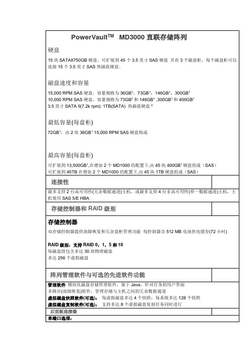
阵列管理软件与可选的先进软件功能
管理软件模块化磁盘存储管理软件,基于Java、针对任务的用户界面
多路径(故障恢复)软件,管理存储与主机之间的冗余数据通道
虚拟磁盘快照软件(可选):每虚拟磁盘多达4个快照;每系统多达128个快照
虚拟磁盘复制软件(可选):支持多达8个虚拟磁盘复制任务同时进行
PowerVaultTMMD3000直联存储阵列
硬盘
15块SATAII750GB硬盘,可扩展到45个3.5英寸SAS硬盘共有3个磁盘柜,每个磁盘柜可以连接15个3.5英寸SAS热插拔硬盘。
磁盘速度和容量
15,000 RPM SAS硬盘,容量规格为36GB1,73GB1,146GB1,300GB1
10,000 RPM SAS硬盘,容量规格为73GB1和146GB1,300GB1和400GB1
Windows 2003 32-bit 2 node clusters & R2
2 node clusters on Windows 2003 EM64T and R2
Windows Storage Server 2003 R2 & 2 node clusters
数量
单台价格
总价
保修
PowerVaultTMMD3000
每个硬盘1个双色LED状态指示灯
存储控制器
每个SAS IN/OUT端口1个双色LED状态指示灯(双端口选项共有3个,单端口选项共有2个)
电池供电高速缓存配有1个单色电池故障LED指示灯
1个单色高速缓存活动状态LED指示灯
2个单色控制器故障和控制器电源LED指示灯
2个单色LED指示灯用于指示以太网链接和速度
相对湿度
Dell PowerVault MD3000i 配置指南说明书
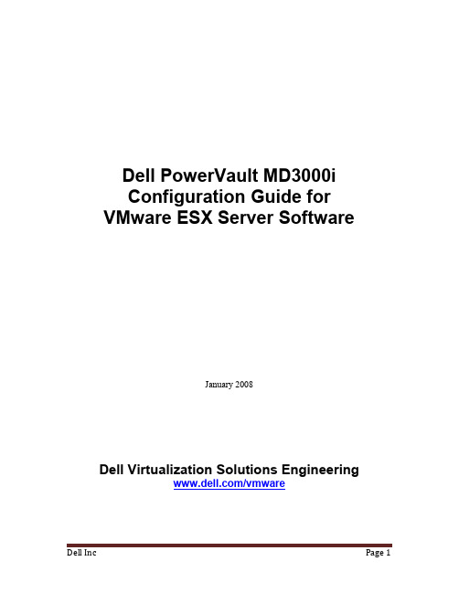
Dell PowerVault MD3000iConfiguration Guide for VMware ESX Server SoftwareJanuary 2008Dell Virtualization Solutions Engineering/vmwareTable of Contents1. Introduction (3)2. Architectural Setup (3)3. iSCSI Connectivity Support (4)4. PowerVault MD3000i Storage Setup and Configuration (4)5. iSCSI Software Initiator Configuration on ESX Server (5)6. Configure iSCSI storage on ESX Server (8)7. References (9)Dell Inc Page 31.IntroductionThe Dell ™PowerVault ™ MD3000i storage solution consists of a standard or high availability configuration. The standard model has a single controller with two 1GbE ports. It can be deployed to support up to 16 hosts non-redundantly. The high availability model has dual controllers with two 1GbE ports per controller for a total of four 1GbE ports. The dual controller option can connect up to 16 fully redundant hosts. This document provides instructions to setup the MD3000i iSCSI storage solution for usage with VMware® ESX Server ™ software.The Dell PowerVault MD3000i iSCSI storage array contains four Ethernet ports through which the VD can be accessed affording both redundancy and availability of data. Provisioning of storage on servers in a VM environment is a multiple step process starting with definition of the server names for host access. The iSCSI connection is then established from the storage subsystem, and after detection and configuration is established as a two way link with the associated ESX server(s), completing the iSCSI communication subsystem. The final step allocates the detected storage to the individual virtual machines (VM’s), where all or part of the configured storage can be assigned to individual VM’s.2. Architectural SetupThe following figure illustrates a typical high availability setup for using the MD3000i in an ESX Server farm. As a best practice, Dell recommends using a separate Gigabit Ethernet network switch to handle iSCSI storage traffic. Two servers are connected to two switches. Each switch has a path to the MD3000i via the two dual port controllers. In this base HA configuration, the servers, switches, and MD3000i ports share the same subnet. The NIC ports serving iSCSI traffic on the ESX servers are teamed.Figure 1: MD3000i High Availability ConfigurationLANESX Server 1MD3000iESX Server 2MD1000MD1000Ethernet Switches3.iSCSI Connectivity SupportOperating System Host Bus AdapterVMware ESX Server 3.5 iSCSI software initiator with ESX Server 4.PowerVault MD3000i Storage Setup and Configuration Create virtual disks on MD3000i using steps described in:/support/edocs/systems/md3000i/en/IG/PDF/IGbk0HR.pdf.After opening the Modular Disk Storage Manager and selecting the MD3000i storage array to be configured, select the Configure tab.Note: in the examples to follow the Storage array “sg23_training” is an MD3000i withvirtual disks already configured using the Create Virtual Disks selection. The new server being added to an existing host group is named “Valhalla”.From the Configure tab1. Select Configure Host Access (Manual).2. Enter the host name for the server which has the ESX Server software is installed.3. Select Linux as the host type.From the next screen, specify the iSCSI Initiator by selecting the New button (lower right on screen). On the Enter New iSCSI Initiator screen enter a name for the iSCSI initiator name. The label is auto-populated from the server name.Figure 2: iSCSI Initiator WindowHost Group configuratio n starts from the following screen titled “Configure Host Access (Manual) –Specify Host Group”. For ESX servers supporting VMotion, HA, and DRS, a host group must be defined so the MD3000i storage subsystem has a configured iSCSI path to each of the hosts.Select “Yes: This host will share access to the same virtual disks with other hosts”If a new host group is desired select the radio button for that option and enter in a namefor your host group using standard host naming conventions (e.g. no spaces etc).Should you already have one or more host groups assigned, select the radio buttonenabling selection from a drop down list of existing host groups. This option is to beused when configuring the second, third, etc. host in a group. Once the host group isselected previously configured hosts for that host group will be displayed. Note thatthese are shown as Linux hosts even though they are configured as ESX servers. Selecting Next provides a Confirmation screen in which the new server being configured is shown and the other previously configured associated hosts are named. For the first server configured in a new host group there will be no associated hosts listed under the Associated host group.Figure 3: Modular Disk Storage Manager Configure TabSelect Finish confirming the new host definition. This initiates the wizard configuration of the new host.On completion,Select Yes to proceed to the next host you wish to configure, orSelect No to end the configuration wizard.Helpful Hint: Record the MD3000i IP address for later configuration5.iSCSI Software Initiator Configuration on ESX ServerThis section lists the steps required to configure the software initiator on the VMware ESX Server. Connect to the ESX server/VirtualCenter using VI Client, and follow the below steps:1. Select Configuration->Security Profile on the ESX server.2. Click on Properties. The Firewall Properties box appears.Figure 5: Firewall Properties Window3. Check Software iSCSI Client.4. Select Configuration->Storage Adapters on the ESX server.5. Select iSCSI software adapter and click on Properties.Figure 6: iSCSI software adapter under Storage Adapters on VI client6. The iSCSI initiator Properties window appears.7. Under the general tab select Configure tab. Select the Enabled checkbox and click OK.Select Close.Figure 7: iSCSI software initiator properties window8. Select iSCSI software adapter under storage. You should now see your iSCSI Targetname listed.Figure 8: iSCSI software adapter after initial configuration9. Select Properties under storage adapters. Select Dynamic Discovery. Select Add.Provide the IP address of the MD3000i and click OK. There may be a slight delay before the process completes.Figure 9: iSCSI software initiator properties window10. Click Close.6.Configure iSCSI storage on ESX ServerConnect to the ESX server/Virtual Center using VI Client and follow the steps below.1. Go to the configuration tab and select Storage Adapters. Select the iSCSI SoftwareAdapter and click Rescan. The newly created iSCSI target and LUN should be visiblefrom the ESX server.Figure 10: iSCSI target and LUNs as visible through VI client2. Go to the configuration tab and select Storage. Click on Add Storage, select Disk/Lunand click Next. Select the newly added storage and click Next.3. Select the newly created iSCSI LUN and click Next.4. Review the disk layout and click Next.5. Provide a name for the VMFS datastore and click Next.6. Select the appropriate block size and capacity for the VMFS datastore and click Next.7. Review the disk layout and click Finish to create the VMFS datastore. The new datastoreis now ready to be used for storing virtual machine images.7. References1. Dell PowerVault MD3000i support documents:/support/edocs/systems/md3000i/2. Drivers download page for MD3000i:/support/downloads/driverslist.aspx?c=us&cs=555&l=en&s=biz&Se rviceTag=&SystemID=PWV_MD3000I&os=NAA&osl=EN3. VMware Virtual Infrastructure 3 Documentation:/support/pubs/vi_pubs.html4. Dell|VMware alliance home page: /vmwareTHIS DOCUMENT IS FOR INFORMATIONAL PURPOSES ONLY, AND MAY CONTAIN TYPOGRAPHICAL ERRORS AND TECHNICAL INACCURACIES. THE CONTENT IS PROVIDED AS IS, WITHOUT EXPRESS OR IMPLIED WARRANTIES OF ANY KIND.Microsoft and Windows are registered trademarks of Microsoft Corporation. VMware is a registered trademark and VMotion, Virtual SMP, and ESX Server are trademarks of VMware, Inc. Intel and Xeon are registered trademarks of Intel Corp. Other trademarks and trade names may be used in this document to refer to either the entities claiming the marks and names or their products. Dell disclaims proprietary interest in the marks and names of others.Copyright 2007 Dell Inc. All rights reserved. Reproduction in any manner whatsoever without the express written permission of Dell Inc. is strictly forbidden. For more information, contact Dell. Information in this document is subject to change without notice.。
计算机MD3000i配置手册

第二章MD3000i RAID 配置方法一、MD3000i 前期设置1、修改主机IP地址到192.168.128.x 网段,如192.168.128.99。
DELL MD3000i 磁盘阵列默认IP地址为192.168.128.101和192.168.128.102。
2、登陆MD3000i管理软件3、选择ISCSI 主机端口,编辑数据访问地址4、指定控制器的IP地址后点‘确定’保存设置。
MD3000i 双控制器,要为每一个端口指定唯一的IP地址,保存成功后,服务器应该可以Ping通该地址。
本例中我们使用MD3000i双控阵列,每端口IP地址分配信息如下:控制器0,0 :192.168.3.221控制器0,1 :10.10.10.3控制器1,0 :192.168.3.222控制器1,1 :10.10.10.4这里我们使用接口0,0和1,0二、配置Iscsi 发起程序1、运行Microsoft iSCSI Initiator 进入设置界面,选择‘Discovery’在此对话框中‘Target Portals‘添加一个数据访问如下图2、在Targets中配置开机自动登陆选择‘Log On‘系统弹出以下对话眶,选择’Automatically……..‘开机自动连接。
注:以上是服务器A的设置,服务器B需要进行同样的设置,只是在连接地址中输入192.168.3.222为数据传输地址,此地址是阵列控制器1,0的端口。
三、配置主机访问1、配置主机访问(手动)2、输入主机名称‘test11’,为第一台服务器的计算机名称,然后选择MSCS CLUSTER单路径3、添加主机访问,注意服务名称与ISCSI启动器名称相对应。
4、输入一个新的主机组,将Test11加入My_Cluster组中。
5、完成服务器Test11的主机访问配置6、创建服务器Test22的主机访问与Test11 基本相同,需要注意的是主机名称和ISCSI启动器的名称需要进行相应选择,最后,将Test22 同样加入My_cluster主机组中。
Dell PowerVault MD3000 RAID 存储设备 硬件说明书

Dell™ PowerVault™ MD3000RAID 存储设备硬件用户手册w w w.d e l l.c o m|s u p p o r t.d e l l.c o m注、注意和警告注:注表示可以帮助您更好地使用计算机的重要信息。
注意:注意表示可能会损坏硬件或导致数据丢失,并告诉您如何避免此类问题。
警告:警告表示可能会导致财产损失、人身伤害甚至死亡。
____________________本说明文件中的信息如有更改,恕不另行通知。
©2007Dell Inc.。
版权所有,翻印必究。
未经 Dell Inc.书面许可,严禁以任何形式进行复制。
本文中使用的商标:Dell、DELL徽标、PowerEdge和 PowerVault 是 Dell Inc. 的商标;Microsoft、Windows、Windows Server 和 MS-DOS是 Microsoft Corporation 在美国和/或其它国家和地区的商标或注册商标;Red Hat、Red Hat Enterprise Linux和Red Hat Linux是 Red Hat, Inc. 在美国和其它国家和地区的注册商标;SUSE 是 Novell, Inc. 在美国和其它国家和地区的注册商标;UNIX是 The Open Group 在美国和其它国家和地区的注册商标。
本说明文件中述及的其它商标和产品名称是指拥有相应商标和产品名称的公司或其制造的产品。
Dell Inc. 对其它公司的商标和产品名称不拥有任何所有权。
型号:AMP012007 年 2 月P/N JR475修订版 A00目录1关于系统 (7)概览 (7)存储设备配置 (7)Modular Disk Storage Manager (8)您可能需要的其它信息 (8)硬件配置 (9)存储设备挡板上的指示灯 (9)前面板指示灯和部件 (10)背面板指示灯和部件 (13)RAID 控制器模块 (13)高速缓存功能和部件 (17)电源设备和冷却风扇部件 (17)2连接 RAID 存储设备 (19)开始之前 (19)关于存储设备连接 (19)连接存储设备 (20)冗余和非冗余 (20)单 SAS 输入端口配置 (20)双 SAS 输入端口配置 (22)连接 MD1000 扩充存储设备 (27)使用先前配置的 MD1000 存储设备进行扩充 (27)使用新的 MD1000 存储设备进行扩充 (28)3使用 RAID 存储设备 (31)物理磁盘、虚拟磁盘和磁盘组 (31)物理磁盘 (31)物理磁盘状态 (31)自我监测分析和报告技术 (SMART) (32)虚拟磁盘和磁盘组 (32)目录3支持的 RAID 级别 (33)RAID 0 (33)RAID 1 (34)RAID 5 (34)RAID 10 (34)RAID 级别的使用 (34)分段大小 (34)热备用和重建 (35)全局热备用 (35)热备用操作 (35)重建 (35)介质错误和不可读扇区 (35)RAID 操作和功能 (36)虚拟磁盘操作 (36)磁盘组操作 (37)RAID 后台操作优先级 (38)虚拟磁盘迁移和磁盘漫游 (39)高级功能 (40)存储分区 (40)主机类型 (41)快照虚拟磁盘 (41)快照资源库虚拟磁盘 (42)虚拟磁盘服务 (42)卷影复制服务 (42)虚拟磁盘复制 (43)同时使用快照和磁盘复制 (44)硬件冗余和故障时转移 (44)冗余和非冗余 (44)多路径软件 (44)主机总线适配器 (45)冗余主机布线 (45)替换或卸下 RAID 控制器模块时 (47)RAID 控制器故障时转移模式 (48)RAID 存储设备导热关闭 (48)更新存储设备固件 (48)4目录RAID 控制器模块固件 (49)物理磁盘固件 (49)扩充存储设备固件 (49)4安装存储设备组件 (51)建议使用的工具 (51)卸下和装回前挡板 (51)卸下和安装物理磁盘 (52)从存储设备中卸下物理磁盘 (52)在存储设备中安装 SAS 物理磁盘 (53)卸下和安装 RAID 控制器模块 (55)卸下 RAID 控制器模块 (55)安装 RAID 控制器模块 (56)卸下和安装 RAID 控制器模块备用电池装置 (56)卸下和安装电源设备/冷却风扇模块 (57)卸下电源设备/冷却风扇模块 (58)安装电源设备/冷却风扇模块 (58)卸下和安装控制面板 (59)卸下控制面板 (59)安装控制面板 (60)卸下和安装中间板 (61)5排除存储设备故障 (63)安全第一 — 为您和您的存储设备着想 (63)启动例行程序 (63)排除外部连接故障 (63)排除受潮存储设备的故障 (63)排除受损存储设备的故障 (64)排除电源设备故障 (64)排除存储设备冷却故障 (65)排除风扇故障 (66)目录5排除 SAS 物理磁盘故障 (66)排除存储设备连接故障 (67)硬控制器故障和锁定条件 (67)无效的存储设备 (68)ECC 错误 (68)PCI 错误 (68)严重条件 (68)非严重条件 (68)6获得帮助 (71)获得帮助 (71)在线服务 (71)自动技术支持服务 (72)订单状态自动查询服务 (72)支持服务 (73)Dell 企业培训 (73)订购时遇到的问题 (73)产品信息 (73)退回项目以要求保修或信用退回 (73)致电之前 (74)与 Dell 联络 (74)词汇表 (95)索引 (101)6目录关于系统Dell™ PowerVault™ MD3000 是 3U 架装式外部独立磁盘冗余阵列 (RAID) 存储设备,它最多可以容纳 15 个 3.0 Gbps、串行连接的 SCSI (SAS) 磁盘。
DELL MD3000I 双机热备简单说明

3000I群集安装简单说明(WINDOWS)
之前看过资料做过3000的双机,其实3000I除了ISCSI,其他和3000一样。
实验用的是一台R200做AD,两台R410做SERVER1和SERVER2,一台3000I双控。
IP如下
AD 192.168.2.3
SERVER1 PRIVATE 192.168.3.1 PUBLIC 192.168.2.1
SERVER2 PRIVATE 192.168.3.2 PUBLIC 192.168.2.2
3000I除了两管理口,就只连了130.101和130.102
群集192.168.2.4
大多数配置过程和3000一样,就简单的说下自己遇到的问题吧(有什么错误还请指正)。
两个节点加入AD的时候是用的域管理员的账号和密码,并非在AD 建立的CLUSTER用户,不知道有人用CLUSTER成功过没。
PRIVATE的模式AUTO就可以使用,不象有的要手工指定,手工指定反倒是不行。
3000I配置主机访问,只有三项,选择CLUSTERED,注意主机名不能和SERVER1,2的服务器重名。
3000I的仲裁是这样的,同事之前做好多次没成功可能和这点有关。
做好之后两个服务器磁盘管理是这样的。
在群集管理器里手工移动组的时候SERVER2在我的电脑里看不到盘符号,不过在磁盘管理里可以看到,而且可以正常使用,SERVER1没
问题,其实这并不影响群集的正常使用,因为手动关闭SERVER1,登陆SERVER2一切正常,我的电脑里盘符都可以看到并且可以正常访问。
END。
MD3000 Windows下安装步骤
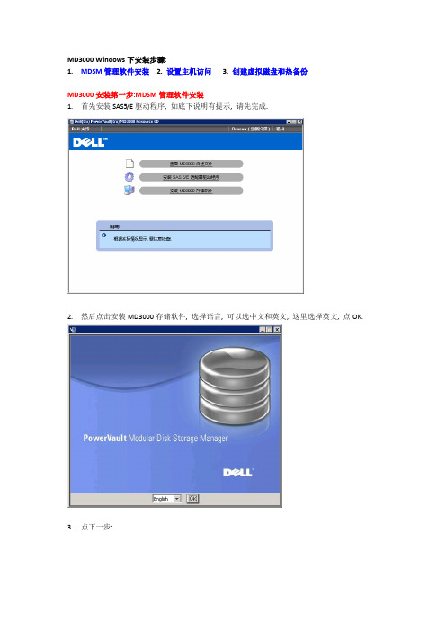
MD3000 Windows下安装步骤:1.MDSM管理软件安装2.设置主机访问3. 创建虚拟磁盘和热备份MD3000安装第一步:MDSM管理软件安装1.首先安装SAS5/E驱动程序, 如底下说明有提示, 请先完成.2.然后点击安装MD3000存储软件, 选择语言, 可以选中文和英文, 这里选择英文, 点OK.3.点下一步:4.接受协议:5.选择安装路径:6.选择安装类型, 如果不知道选什么, 请选择全安装:7.选择自动启动监视:8.提示所需空间:9.提示安装完成:10.如有提示重启请确认.MD3000安装第二步: 设置主机访问1.打开开始→程序→DELL→MD Storage Manager→Modular Disk Storage Manager Client2.选择自动, 开始搜索(手动分为带内和带外管理, 分别代表通过SAS管理和通过管理网口管理)3.一两分钟后显示搜索到的服务器和存储:4.点关闭后, 可以看到存储的大概配置信息:5.重新打开后, 可以看到带内和带外的IP地址.(带外IP地址就是两个控制器的IP地址, 默认是192.168.128.101; 192.168.128.102)6.更改网络配置(根据需要可选)更改IP地址会引起带外管理重新配置. 不影响带内管理7.配置主机访问: 先看自动配置: (手动和自动任选一项)8. 把左边可用的主机加到右边:9. 点击确定即可.10. 手动配置主机访问:11. 输入主机名, 选择主机类型:12. 点击下一步:13. 选择对应的SAS卡WWN:14. 选择创建主机或主机组(针对Cluster)15. 点击完成.MD3000安装第三步: 创建虚拟磁盘和热备份1.选择创建虚拟磁盘:2.显示没有磁盘组, 点下一步:3.手动创建:4.选择磁盘和阵列级别:5.点击计算容量:6.选择要创建的虚拟磁盘大小和IO参数:7.选择要把该虚拟磁盘分配给哪一台主机使用:8.如果有多余的磁盘, 建议配置一块热备份磁盘:9.手动配置:10.选择硬盘组合, 点分配:11.本例选了两块硬盘做热备:12.点击完成.13.打开该服务器的设备管理器, 刷新14.查看是否有MD3000开头的磁盘, 如没有, 请重启机器:15.打开磁盘管理器, 配置分区:。
MD3000i配置指南(多路径)
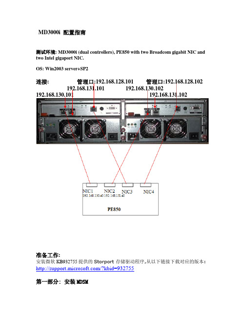
MD3000i 配置指南测试环境: MD3000i (dual controllers), PE850 with two Broadcom gigabit NIC and two Intel gigaport NIC.OS: Win2003 server+SP2连接: 管理口:192.168.128.101 管理口:192.168.128.102 192.168.131.101 192.168.130.102192.168.130.101 192.168.131.102准备工作:安装微软KB932755提供的Storport 存储驱动程序,从以下链接下载对应的版本: /?kbid=932755第一部分: 安装MDSM在服务器上安装MDSM管理软件,选择语言点击下一步安装选择安装目录选择典型安装完成安装选择自动搜索MD3000搜索到带内管理方式的MD3000,带内管理需要SM client 和SM agent 和Access Virtual Disk也可以选择手动方式,使用带外方式连接,带外需要SM client 和SM agent和网线连接192.168.128.101和192.168.128.102 带外管理方式登陆选择“配置”-“创建虚拟磁盘”,来进行RAID和VD的创建选择“手动”创建RAID配置RAID5创建虚拟磁盘(VD),指定数据块大小把VD和服务器相对应。
完成RAID和VD配置选择“配置”-“配置热备份”配置热备份硬盘手动指定热备份硬盘选择“配置”-“创建主机到虚拟磁盘的映射”,创建VD和服务器对应关系第二部分安装MS Initiator,配置Chap,启用Vlan support:1.微软提供了各个版本的initiator可供下载,这里我们安装V2.04,从随机光盘里找到该文件,直接运行:2.因为安装MDSM时已经安装了MPIO,所以这里不要选择安装MPIO:3.安装完成后,打开Initiator,选择Discovery,分别输入两个Target的IP地址: 192.168.130.104 /192.168.131.104,端口号建议使用默认:4.选择target,点击 logon,分别选中”automatically restore…”和”enable muti-path”选项,然后点击”advanced”, local adpater选择microsoft iscsi initiator,分别选择源IP(服务器网卡IP)和Target portal(该网卡连接的MD3000i的控制卡接口IP):5.再次点击logon, 分别选中”automatically restore…”和”enable muti-path”选项,然后点击”advanced”, local adpater选择microsoft iscsi initiator,分别选择源IP(服务器另一网卡IP)和Target portal(该网卡连接的MD3000i的另一块控制卡接口IP):6.这时选择Target的details查看,会看到系统启动了两个Session连接到MD3000i:7.从MDSM里的ISCSI→查看/结束ISCSI会话选项,我们也可以看到盘柜和PE850(主机statition40)建立起了两个会话:8.接下来即可创建虚拟磁盘,进行主机映射,比如下图是分配给本机2个虚拟磁盘后,在设备管理器里看到的状态:9.如果需要启用CHAP认证,那么在MDSM里,打开ISCSI→更改目标验证:10.选择CHAP,打开CHAP秘密,输入验证码:11.在Initiator里打开CHAP: 选择Target→Logon→Advanced,选中CHAP logon information,输入验证码:12.启用Vlan支持,以下只是示例,我们将服务器网卡和其对应连接的MD3000i控制卡网口配置到同一Vlan里.实际应用时不一定必须采用此方法,也可以在交换机上按所需的端口划分Vlan. 这里我们选择ISCSI 配置ISCSI主机端口,选择相应的端口,点击”高级”,在其中我们不但可以设置其Vlan,还可以开启对802.1P数据包优先级,巨型帧等支持及更改ISCSI TCP 侦听端口:13.将对应的服务器网卡加到对应的Vlan里:经过以上的配置,即可实现只有和对应MD3000i控制口相同的Vlan的initiator(网卡)才能访问的目的.附:常常有客户误删除盘柜上的Access Lun,导致无法对其进行带内管理,通过用Smcli我们可以添加Access Lun 给相应的主机:C:\Program Files\Dell\MD Storage Manager\client>SMcli 192.168.128.103 -c "set ac cessVirtualDisk logicalUnitNumber=31 host=\"station4\";"。
MD3K(二)-初始化盘柜和网络设置
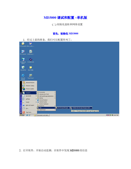
MD3000 调试和配置–单机版(二) 初始化盘柜和网络设置首先,初始化MD3000 1.经过上面的准备,我们可以配置阵列了:2.打开软件,开始自动监测,在软件中发现MD3000的信息2.如果MD3000中有残留的信息,我们可用命令行的方法,先对MD3000进行初始化。
当然,这一步也可以跳过4.首先,start---run----cmd 打开MSdos命令行5.然后,在命令行中,进入MDSM程序所在的子目录运行 cd C:\Program Files\Dell\MD Storage Manager\client\6.进入目录后,运行: SMcli 127.0.0.1 (如果是带外管理,把127.0.0.1替换成相应的控制器访问IP)注意大小写,回车,然后就进入了MD3000的命令行模式7.在命令行模式下,运行下面的命令:clear storageArray configuration;请注意大小写,还有最后的分号回车,大概5分钟后,MD3k前面板左上角的状态指示灯会变成紫色,待指示灯由紫色恢复成蓝色后,初始化完成8.完成后,MD3000就可以恢复到初始的状态了下面,来看如何设置MD3000控制器的访问IPMD3000即可以用带内方式管理(通过SAS数据线),也可以用带外方式辅助管理(通过连接控制器的网线)。
带外管理对于系统的调试和故障排查非常有用。
1.选择 modify –Network configure2.在这里可以修改控制模块的IP默认的IP :控制器0 --- 192.168.128.101 (正对机器右侧的控制器为0号)控制器1--- 192.168.128.102特别提醒:IP地址一旦忘记,需要在工厂模式下恢复,操作非常繁琐请尽量保留默认IP或妥善记录更改后的IP3.用网线连接设备,等待3-5分钟,确认可以ping通控制器IP后,就可以使用带外管理了点选阵列名称旁边的new 选项,然后让软件自动扫描一次4.可以看到两种管理方式都有了带内管理(通过SAS数据线管理): 127.0.0.1 带外管理(通过网线):192.168.128.101。
带 Microsoft Windows Server 故障转移群集的 Dell PowerVault
带 Microsoft ® Windows Server ® 故障转移群集的 Dell™ PowerVault™ MD3000 存储阵列硬件安装与故障排除指南简介群集硬件的布线准备用于群集的系统故障排除群集数据表注、注意和警告本说明文件中的信息如有更改,恕不另行通知。
© 2008 Dell Inc. 版权所有,翻印必究。
未经 Dell Inc. 书面许可,严禁以任何形式进行复制。
本文中使用的商标:Dell 、DELL 徽标、PowerEdge 、 PowerVault 和 OpenManage 是 Dell Inc. 的商标;Microsoft 、SQL Server 、Windows 、 和 Windows NT 是 Microsoft Corporation 在美国和/或其它国家和地区的商标或注册商标。
本文中述及的其它商标和产品名称是指拥有相应商标和产品名称的公司或其制造的产品。
Dell Inc. 对本公司的商标和产品名称之外的其它商标和产品名称不拥有任何专有权。
2008 年 4 月 修订版 A00注: "注"表示可以帮助您更好地使用计算机的重要信息。
注意: "注意"表示可能会损坏硬件或导致数据丢失,并告诉您如何避免此类问题。
警告: "警告"表示可能会导致财产损失、人身伤害甚至死亡。
返回目录页面群集硬件的布线带Microsoft ® Windows Server ® 故障转移群集的 Dell™ PowerVault™ MD3000 存储阵列硬件安装与故障排除指南鼠标、键盘和显示器的布线电源设备的布线公用网络和专用网络的布线存储系统的布线以下部分将帮助您将电源、网络和存储电缆连接至群集。
连接硬件组件后,本文档中的后续部分将向您提供配置群集的说明。
鼠标、键盘和显示器的布线在机架中安装群集配置时,必须安装切换器盒,以将鼠标、键盘和显示器连接至节点。
RAID配置教程详解

RAID配置教程详解
RAID是Redundant Array of Independent(or Inexpensive)
Disks(冗余硬盘阵列)的缩写,它是一种高可靠的软件磁盘阵列技术,有效地提高了硬件、软件系统的数据读写性能及存储容量。
RAID可以将多块硬盘按指定的技术拼接成一个逻辑卷,具有更高的存储效率、更低的数据损坏风险,满足系统对高可靠性、高容量、高性能的要求。
1)安装驱动:在安装RAID硬件之前,需要先装驱动,为硬件与操作系统建立桥梁。
2)安装RAID硬件:将选购的RAID硬件安装到主机上,打开服务器箱,将RAID卡安装到主板上,安装完成后,关闭服务器箱,开机前检查硬件安装状况无误,再接入硬盘、电源线、数据线。
3)初始化RAID:硬件安装完成后,即可进入RAID控制器的管理界面,将存储磁盘分为一个或多个磁盘阵列,并可设定阵列的模式,如RAID0、RAID1、RAID5等,并设置磁盘阵列镜像、检查数据可靠性、设置热备份等。
4)安装系统:RAID硬件的设置完成后,可安装系统,安装时可以选择RAID驱动,安装完成后,系统会自动识别RAID阵列、磁盘,然后可正常使用。
5)数据备份:RAID数据必须定期备份,为了能够恢复RAID阵列,应定期备份重要数据,以免发生硬件故障时,系统数据失去。
MD3000i更换RAID控制器模块说明书
WARNING: A WARNING indicates a potential for property damage, personal injury, or death.Replacing a RAID Controller Module in a Single-Controller MD3000iThis document describes how to replace a failed RAID controller module in a single-controller MD3000i. After replacing the RAID controller, you will also need to update its controller and NVSRAM firmware. These steps are described in "Updating RAID Controller and NVSRAM Firmware on the Replacement RAID Controller Module" later in this document.Replacing the RAID Controller ModuleWARNING: Always wear a wrist grounding strap when handling equipment withstatic-sensitive components. See your Product Information Guide for safetyinformation.Removing the RAID Controller Module1Power down the MD3000i enclosure.2Disconnect all cables from the failed RAID controller module.3Push up on the release tab on the left side of the module (see Figure 1).4At the same time, pull out on the release lever. When the lever is pulled out, the controller module partially ejects from the enclosure.5Remove the module from the enclosure and place it on a flat, secure surface.CAUTION: To avoid damage to the sensitive EMI (ElectroMagnetic Interference)contacts on the bottom of the controller module, do not stack or place the module on a hard surface.Figure 1.Removing and Installing a RAID Controller ModuleInstalling a Replacement RAID Controller Module1Carefully insert the replacement RAID controller module into the empty module slot.2Push the module into the back of the slot until it is firmly seated in the backplane connector (see Figure 1).3Push the release lever in (towards the enclosure) until the module is retracted into the slot and is secure.Proceed to the next section to update the RAID controller and NVSRAM firmware on the new controller.1release tab 2release leverUpdating RAID Controller and NVSRAM Firmware on the Replacement RAID Controller ModuleThe following procedure is required only if a single controller storage array enters lockdown mode after replacement of a failed controller.To update the RAID controller module and NVSRAM firmware, the following items will be required:•Server, workstation, or laptop computer with access to the management port of the RAID controller module•Single Controller Replacement UtilityUsing the Single Controller Replacement UtilityNOTE: The Single Controller Replacement Utility will not update any RAID controller that is not in lockdown mode. If your RAID controller is not in lockdown mode, use the update procedure described in the Dell TM PowerVault TM MD3000i User’s Guide.NOTE: In order to update the firmware, the RAID enclosure must contain at least two disk drives.The Single Controller Replacement Utility should be run after replacing a failed controller in a single-controller system. The utility ensures that the firmware version in the replacement controller is in sync with the firmware expected by the virtual disks. After running the utility, the storage array should return to the configuration it was in prior to the controller failure.The utility can be run from any computer with access to the management port of the storage array by following these steps:1Extract all files and folders from the utility .zip file to a temporary location. 2Navigate to the location of the extracted files.If you are using a Windows system, run the simplex.bat file.If you are using a Linux system, execute the simplex.sh file.A GUI-based wizard will guide you through the remaining steps necessary toupdate the controller.3When the wizard completes, click Finish.The update process is complete.____________________Information in this document is subject to change without notice.©2008Dell Inc.All rights reserved.Reproduction in any manner whatsoever without the written permission of Dell Inc.is strictly forbidden. Trademarks used in this text: Dell, the DELL logo, and PowerVault are trademarks of Dell Inc. Other trademarks and trade names may be used in this document to refer to either the entities claiming the marks and names or their products. Microsoft and Windows are either trademarks or registered trademarks of Microsoft Corporation in the United States and/or other countries. Dell Inc. disclaims any proprietary interest in trademarks and trade names other than its own.December 2008。
md3000磁阵安装全过程
md3000磁阵安装全过程关键字: server1、安装环境(CENTOS5.3[redhat5.1.9],+两台R900服务器+MD3000阵列)2、硬件安装安装SAS RAID卡,我们购买的MD3000后面只有两个IN口,只能做到单程双控,打开服务器盖板,我们选择右边第三个插槽安装SAS RAID卡,轻轻扳开绿色的塑料卡槽,取出贴片挡板,将卡插入卡槽中,盖上塑料卡槽,盖上服务器盖板,一台就装好了(另一台同样操作)安装SAS 4X线,由于后面只有两个IN 口,所以选择SAS RAID卡的上面的接口,都用一个SAS 4X线与服务器连接至此硬件部分安装完毕3、重新开机(REDHAT 5以上版本不需要安装SAS 5/E的硬件驱动,小于他则需要安装驱动,我们是REDHAT5.1,不需要安装)开机在自检的时候系统会有一个初始化SAS的地方,我们可以ctrl + c进去+enter ,用方向键移到SAS1068+enter 进入后再用方向键选择SAS TOPDOGY(没有拼全)+enter ,在用方向键移动到direct attach device + enter,你就能看见磁阵上的硬盘了,说明不需要安装驱动。
4、安装软件,在安装的时候请将另外一台机器关掉,放入MD3000的随机光盘,(如果要安装驱动软件,进入到/linux/RPMS/rh5的目录安装SAS5/E的驱动 rpm mptlinux包,我们这里不需要)开始安装 MD3000的管理软件,在 /linux/app目录下面,客户的 linux需要X-windows.下面有一个SMIA-LINUX……的bin安装包./SMIA-LINUX…….bin来安装他,这时后弹出一个安装的图形界面,一步一步的执行下去就可以完成安装。
选择默认的安装路径(注意管理软件的默认安装路径/opt/dell/mdstoragemanager)安装完成后会在桌面生成两个程序启动连接,点击下面那个柱装的图标,进入软件这时注意了,磁阵管理分为带内管理和带外管理,带内管理是通过SAS线内管理,带外管理是通过网线进行的的带外管理这里安装的时候很奇怪,带内管理没有WIDDOWS MSCS CLUSTER-单个路径的选项,这里我们需要用笔记本电脑通过网线进行带外管理。
DELL Dell PowerVault MD3000 Systems 说明书
Dell™ PowerVault™MD3000Systems Information UpdateNotes, Cautions, and WarningsNOTE: A NOTE indicates important information that helps you make better use of your computer.CAUTION: A CAUTION indicates potential damage to hardware or loss of data if instructions are not followed.WARNING: A WARNING indicates a potential for property damage, personalinjury, or death.____________________Information in this document is subject to change without notice.©2008–2009Dell Inc.All rights reserved.Reproduction of these materials in any manner whatsoever without the written permission of Dell Inc. is strictly forbidden.Trademarks used in this text: Dell, the DELL logo, and PowerVault are trademarks of Dell Inc.; Microsoft, Windows, and Windows Server are either trademarks or registered trademarks of Microsoft Corporation in the United States and/or other countries; SUSE is a registered trademark of Novell, Inc., in the United States and other countries; Red Hat and Red Hat Enterprise Linux are registered trademarks of Red Hat, Inc. in the United States and other countries.Other trademarks and trade names may be used in this document to refer to either the entities claiming the marks and names or their products. Dell Inc. disclaims any proprietary interest in trademarks and trade names other than its own.September 2009Rev. A02ContentsDetermining Your Firmware Version (5)Important Information Before Upgrading YourFirmware (5)Performance Affected after Upgrading to SecondGeneration Firmware (5)Virtual Disk Copy Operation on SATA Disks (6)Load Balancing in Microsoft Windows Server 2008 (6)Installing Linux Operating System (6)Battery Learn Cycle (6)Creating Host to Virtual Disk Mappings (7)Additional Disk Group and Virtual Disk ExpansionInformation (7)Storage Manager for SANs (8)Unable to Assign LUNs to Windows 2008Server (8)Array Password Reset Using Microsoft WindowsServer 2008 (8)Modular Disk Storage Manager (9)Physical Disk Migration (9)RAID Level (9)Change Disk Group RAID Level (9)RAID Level Migration Requirements (10)Contents3Under-Reported Disk Capacity (10)Configuration File Write Error (10)Limitations of NTFS-Formatted Disks (11)Password Reset Procedure (11)Updates to the MD3000 Documentation (12)Hardware Owner’s Manual (12)Command Line Interface Guide (12)Installation Guide (12)4ContentsDetermining Your Firmware VersionTo determine if your software is first generation or second generation, perform the following steps:1Connect to the system using the Dell™ PowerVault™ MD Storage Manager.2Select the Support tab.3Click Storage Array Profile.Note the firmware version:If it is 06.xx.xx.xx, it is first generation.If it is 07.xx.xx.xx, it is second generation.Important Information Before Upgrading Your FirmwarePrior to performing the firmware upgrade, perform a complete backup of the data, and use the Gather Support Information tool to save the system configuration. This recommendation applies whenever you make changes to your configuration.Performance Affected after Upgrading to Second Generation FirmwareAfter upgrading to second generation firmware, you may experience a temporary performance impact. This impact is caused by the second generation firmware, which adds smart-battery functionality to the MD3000. In order to accurately measure battery parameters, the batteries are taken through a “learn cycle” and the system’s write cache is disabled for the duration of the learn cycle. The first learn cycle starts soon after the firmware upgrade is completed and takes around 15 hours to complete. During this time, you may experience a temporary performance slowdown for certain kinds of file operations as the write cache is disabled. Once the learn cycle is complete, the write cache is automatically enabled.Future learn cycles are scheduled for every 13 weeks. Y ou can adjust the day and time of the day of future learn cycles using MD Storage Manager (click Tools and select Change Battery Settings).Information Update5Virtual Disk Copy Operation on SATA DisksA virtual disk copy operation may take much longer when a new copy is created on SATA disks. To improve the performance, first create the virtual disk. After the virtual disk is initialized, start the virtual disk copy operation. Load Balancing in Microsoft Windows Server 2008Load balancing in Microsoft® Windows Server® 2008 is provided by the MPIO driver under the MPIO tab. For information about accessing the MPIO tab, see the Installation Guide at /manuals. The following options are supported by MD3000:•Least Path Weight•Least Queue DepthInstalling Linux Operating SystemDuring a Linux operating system installation, the installer lists all the volumes that are discovered from MD3000, including virtual disks that are mapped to the host and Universal Xport. If the operating system needs to be installed on an MD3000 virtual disk, you must ensure that you select the appropriate virtual disk. The array does not respond if you select the Universal Xport disk(s) for installation.Battery Learn CycleIn second generation firmware systems, the cache offload battery undergoes a learn cycle once in every 13 weeks to ensure that the battery is in a good state. The learn cycle performs a complete discharge of the battery followed by a complete recharge. During this cycle, the system cache is disabled on all virtual disks in the system. There may be a temporary impact on the performance of the system when the battery undergoes a learn cycle. A learn cycle takes place under the following situations:•First time upgrade from first generation firmware to second generation firmware•Once in every 13 weeks6Information UpdateThe next scheduled learn cycle can be seen under Tools→Change Battery Settings in the MD Storage Manager. The learn cycle can be postponed by up to seven days at a time through the GUI. Y ou can also use the following SMcli command to postpone a learn cycle: set storageArray learnCycleDate daysToNextLearnCycle=[x]For more information, see the Command Line Interface Guide at /manuals.Creating Host to Virtual Disk MappingsY ou can create Host-to-Virtual Disk mappings to a host group or to a single host. If you have created the mapping to a host that is part of a host group, the mapped host alone will have access to the virtual disk. Additional Disk Group and Virtual Disk Expansion InformationTo expand disks groups or virtual disks, you can use the MD Storage Manager or the command line interface. It is only possible to add one disk at a time or two in the case of RAID10 to expand the disk group.To expand the virtual disk using the command line interface, type: set virtualDisk [VDname] addCapacity=sizetobeaddedFor more information, see the Command Line Interface Guide at /manuals.During disk group and virtual disk expansion operations, you have complete access to the virtual disks and disk group redundancy is maintained at all times. The impact on the performance is minimal during the operation.For more information, see the User's Guide at /manuals.Information Update7Storage Manager for SANsUnable to Assign LUNs to Windows 2008 ServerThe Windows Server 2008 Storage Manager for SANs utility can be used to create and manage virtual disks in the MD3000 from the host server. If the host server contains SAS 5/i HBAs, the SAS 5/i ports must be disabled in the Storage Manager for SANs utility to prevent issues with assigning virtual disks (LUNs) to the host server.Perform the following steps:1Click LUN Management.2Click Manage Server Connection.3Select the host server.4In the Fiber Channel Ports tab, disable all the SAS 5/i ports and leave the SAS5/e ports enabled.There are 8 SAS 5/i ports per SAS 5/i HBA in the host server. The HBA Port WWN has the following format: xx:xx:xx:xx:xx:xx:xx:00 toxx:xx:xx:xx:xx:xx:xx:07.NOTE: SAS 5/e HBAs have two ports with HBA Port WWN as follows:yy:yy:yy:yy:yy:yy:yy:00 and yy:yy:yy:yy:yy:yy:yy:04Array Password Reset Using Microsoft Windows Server 2008To reset a lost or forgotten password on an MD3000 array, a command must be issued via the serial port on either controller in the array to clear the existing password. This task is accomplished through COM port connection from a server, workstation or laptop to a controller on the MD3000 array.On most Windows operating systems, the HyperTerminal application is used to establish the COM port connection to the serial port on the controller. However, HyperTerminal is not available on Windows Server 2008 systems.8Information UpdateComplete the following steps to reset the password to an MD3000 array if your system is running the Windows Server 2008 operating system:1Obtain a terminal application capable of COM port connections.2Configure the application to use the communication settings as described on page 23 of the Dell PowerVault Modular Disk Storage Manager User’s Guide.3Proceed with the password reset procedure described on page 24 of the User’s Guide.Modular Disk Storage ManagerThe following updates apply to the Modular Disk Storage Manager(MD Storage Manager):•When the MD Storage Manager is installed on Red Hat® Enterprise Linux® systems or SUSE® Linux Enterprise Servers, or when theMD Storage Manager is running on SUSE Linux Enterprise Servers,Japanese and Simplified Chinese are not supported.Physical Disk MigrationCold power-up migration of physical disk s from one MD3000 duplex configuration to another MD3000 duplex configuration is supported only when all physical disk s are moved from one system to another. No other migrations, including partial physical disk migration and RAID controller module migration, are supported.RAID LevelChange Disk Group RAID LevelFollow these instructions to change the RAID level of a disk group as needed: 1In MD Storage Manager, click the Modify tab and click Change Disk Group RAID Level.2Select the disk group that you want to modify.3Select the new RAID level from the drop-down menu.4Click Change to start the process.Information Update910Information UpdateNOTE: Dell recommends backing up the disk group before modifying the RAIDlevel.NOTE: The number of disks in the disk group should meet its RAID level criteria. RAID1 and RAID10 require an even number of disks. On the MD3000, RAID 5requires a minimum of 3disks and RAID 6 requires a minimum of 5 disks. You may need to add free capacity to the disk group before changing the RAID level.RAID Level Migration RequirementsSuccessful RAID Level Migration (RLM) requires that the appropriate number of physical disk s are present in your disk group. To perform RLM from a RAID 1 or RAID 10 to an odd-number of physical disks (five or more) in RAID 5, first add an even number of disks to the RAID 1 or RAID 10, convert to RAID 5, then add another physical disk to make the count odd.Under-Reported Disk CapacityThe unit Gigabyte (GB) is often used to refer to calculation of both 109bytes and 230 bytes. The MD Storage Manager calculates hard disk capacity in GB using 230 bytes as compared to 109 that is used by hard disk manufacturers, and therefore displays a smaller capacity than reported by the hard drive vendor. There is no actual loss of available data capacity, and the MD3000 only reserves 512 MB (106) of space per hard disk for meta-data usage.Configuration File Write ErrorUsing the MD Storage Manager with Microsoft Windows Server 2008 or Microsoft Windows Vista can result in a Configuration File Write Error . The MD Storage Manager will be unable to save any changes to the configuration files. This error is seen when the application is run as a user without Local Administrator privileges. MD Storage Manager requires Local Administrator privileges for full functionality.Workaround: This error can be bypassed by running the MD StorageManager with local administrator privileges. This can be set by right-clicking the shortcut and clicking Run as Administrator . This setting can be made permanent by modifying the shortcut properties and enabling Always run as administrator .Limitations of NTFS-Formatted DisksThe following error may occur when formatting virtual disks larger than 2TB using the NTFS protocol:The format operation did not complete because the cluster count is higher than expected.This error is caused by the limitations of NTFS-formatted disks based on cluster size.Table 1-1.Limitations of NTFS-Formatted Disks Based on Cluster SizeCluster size Maximum NTFS Volume Size (bytes RAW)5122,199,023,255,040 (2TB)1,0244,398,046,510,080 (4TB)2,0488,796,093,020,160 (8TB)4,09617,592,186,040,320 (16TB)8,19235,184,372,080,640 (32TB)16,38470,368,744,161,280 (64TB)32,768140,737,488,322,560 (128TB)65,536281,474,976,645,120 (256TB)As seen in T able1-1, you will need to modify cluster size to format certain virtual disks. T o expand existing virtual disks beyond the limits, back up the data on any existing virtual disks and reformat the virtual disk with the new cluster size. Please refer to Microsoft KB302873 and KB814594 for additional information. Password Reset ProcedureThe password reset procedure differs slightly between the first generation and second generation controllers. Please see the latest version of theDell PowerVault MD3000 RAID Controller Password Reset on for details on the password reset procedures.Information Update11Updates to the MD3000 DocumentationHardware Owner’s ManualThe following update applies to the Dell™ PowerVault™ MD3000 RAID Enclosure Hardware Owner’s Manual:Table 1-1 and Table 1-2—Flashing amber in the enclosure status LED indicates that the solution is in a non-optimal state. See the MD Storage Manager error recovery console or contact technical support to resolve this state.Command Line Interface GuideThe following are the corrections/additions in the list of parameters described in Table 1-2:•d: Used to display the array details from the array configuration file.•V: Used along with the -d parameter to display the version of SMcli that is connected to the array.Installation GuideThe following update applies to the Dell™ PowerVault™ Modular Disk 3000 Installation Guide:•The multi-pathing MPP driver is installed directly from the CD on Linux.Step 12 of the host installation procedure should read - "Return to the CD main menu and select the Install Multi-Pathing Driver option".•The note stating that the MD3000 supports only round robin load-balancing policies is no longer applicable.12Information UpdateDell™ PowerVault™MD3000系统信息更新注、小心和警告注:“注”表示可以帮助您更好地使用计算机的重要信息。
DELL_MD3000 群集手册
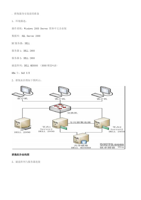
. 群集服务安装前的准备1、环境描述:操作系统:Windows 2003 Server 简体中文企业版数据库: SQL Server 2000DC服务器:DELL服务器1:DELL 2950服务器2:DELL 2950磁盘阵列:DELL MD3000 (300G硬盘*15)HBA卡:SAS 5/E2、群集拓扑图如下图所示:群集拓扑结构图2、磁盘阵列与服务器连接SAS 5/E 上面有两个接口分别为0、1,MD3000上一般有两个In接口,和一个Out接口。
接主机一般使用两个In接口。
需要注意的是:如果一台服务器的SAS卡使用了ID为“1”的接口,另一台则需要使用ID为“0”的接口。
如上图所示。
3、账号信息:本地管理员账号:administrator密码:********域管理员账号:administrator(51654874)密码:********群集管理员账号:cluster (域管理员组)密码:********SQL管理员账号:sqladmin (域管理员组)密码:********SA密码:sa4、服务器信息:域服务器服务器名:DCIP地址:192.168.2.5子网掩网:255.255.255.0网关:192.168.2.1DNS:192.168.2.5域名:Test.local域还原模式密码:******** 第一台服务器服务器名:Server1公网IP地址:192.168.2.2 子网掩网:255.255.255.0网关:192.168.2.1DNS:192.168.2.5心跳侦测地址:192.168.18.1 子网掩码:255.255.255.0第二台服务器服务器名:Server2公网IP地址:192.168.2.3 子网掩网:255.255.255.0网关:192.168.2.1DNS:192.168.2.5心跳侦测地址:192.168.18.2子网掩码:255.255.255.05、群集5.1 群集名称:data.test.local5.1虚拟IP地址:192.168.2.556、SQL Server 20006.1 虚拟服务器名称:VIRSQLCLUSTER6.2 虚拟IP地址:192.168.2.667、磁盘配置:Label DeviceC: SYSTEM 40GB | 本机D: DATA 96GB | 本机E: CDROM | 本机P: DATA 300GB | 磁盘阵列S: SHARE 剩余空间 | 磁盘阵列Q: Quorum 1GB | 磁盘阵列8、MD3000 控制器管理IP:控制器0:192.168.2.101控制器1:192.168.2.1022. 群集服务器安装及配置 2.1 硬件设备情况步骤节点1 节点2 存储注释安装配置系统上电上电断电检查所有共享总线上的存储设备是否都已经断电,给各节点上电。
MD3000集群文件共享操作方法

MD3000集群文件共享操作方法(原)一、应用目的:中心需要共享存储中心,需要的要求为能提供高可用性和高速率的课件文件的点播。
由于SAN环境成本较高,现采用磁盘阵列加存储服务器的方式向流媒体服务器和课件服务器提供NAS服务。
NAS机头采用两台服务器集群的方式。
二、环境构成:a)服务器:两台DELL 1950服务器(CPU1.6*2 4GB 146GB*2 PERC4/DC Raid1 1000M*2)b)磁盘阵列:DELL MD3000 (双口双控制卡300GBSAS*15 SAS5/E卡*4)三、操作方法:a)MD3000的配置按照DELL的建议,我们采用双机双冗余HBA卡方式构建MD3000环境。
先开启MD3000磁盘阵列柜,需要开启两个电源模块(否则工作的电源模块的风扇将会以超负荷工作,声音很响)。
然后开启所有的服务器。
登入所有1950服务器。
安装SAS卡驱动。
驱动可通过插入随机附带的MD3000的盘,会自动运行检测SAS卡的驱动,如果要安装只需根据操作进行安装即可。
安装Modular Disk Storage Manager Client。
第一次运行时使用自动选项添加存储阵列,然后再在Tools菜单栏中选择重命名,将新添的阵列命名为自己需要的。
再在Configure菜单栏中设置Host Access可以看到,1950-1(主机名为MD3000-1)和1950-2(主机名为MD3000-2)分别连接的HBA卡的物理地址,和他们的连接存储的类型(集群型)。
然后我们将需要建立集群的主机和附带的HBA卡加入一个组中,通过按Configure-Create Host Group。
在组名中键入新组名,我们设为nas,将所有左边的设备都加到右边的组中,点OK,此时在Modify的Edit Topology中我们可以看见如下图:接着进行盘柜资源的分配,一般首先设置热备盘,在Configure菜单下有Configure Hot Spares选项。
MD3K(三)虚拟磁盘的的创建

MD3000 调试和配置–单机版(三 ) 如何创建和管理虚拟磁盘首先,我们要在MD3000中创建主机1.选择 configure – create Host access ,选用手动方式2.选择创建主机的方式,这里是单机,所以选:non-cluster host name 要填写服务器的主机名,注意要大写3.选择HBA卡每块SAS5/E有两个接口,每个接口都被认为是一个独立HBA卡,这里我们连接了两个接口,将它们都选择上4.暂时不作主机组设置(在双机cluster模式中,我们要设置主机组),直接继续:5.一路继续,完成后,在 modify –Edit topology 中查看配置好的主机6.可以看到,主机下有两块HBA卡了接下来,我们要配置Virtual Lun(虚拟磁盘) 1.选择 configure --- create Vitual Disk2.Raid类型选择raid5 ,将左边选中的硬盘移动到右边3.注意,选择完硬盘后,一定要:calculate capacity (计算容量),不然逻辑磁盘无法被识别4.继续,现在Disk Group 已经建立,我们可以在DiskGroup中划出一定的空间,创建一个Virtual Lun (有时也称逻辑驱动器)注意:一个V-Lun,在window中就相当于一个独立的磁盘。
这里划出了2G的空间创建V-Lun 1,剩余空间回头还可以建立新的V-LunMD3K中单个V-Lun最大容量是2T,大于这个容量,系统会自动限制到2T5.这里可以直接把创建的 V-Lun 映射给某个主机,当然,也可以不映射先继续6.创建完Virtual-Lun,我们还可以创建一块 hotspare 热备盘选择 configure ---hot spare7.然后选择手动,在右边选择一块热备盘,放入左边的列表中8.如果要撤销 hot spare 盘,请选择下面的 unassign最后,让我们建立 Virtual Lun 和 Host 主机间的映射关系1.现在V-Lun和Host 主机我们都已经创建完成,下面需要将两者映射在一起选择:configure ---create Host to V-disk mapping2.选择要挂接V-Lun的主机3.选择目标 V-Lun。
DELL服务器双机热备实施步骤
DELL服务器双机热备实施步骤双机热备实施步骤一、双机热备概述二、安装概述三、实施前准备四、安装操作系统(Windows Server 2003 Enterprise Edition)五、配置存储(共享磁盘)六、配置网卡七、新建域(AD)、DNS八、配置群集服务(双机热备)九、测试一、双机热备概述双机热备包括广义与狭义两种。
从广义上讲,就是对于重要的服务,使用两台服务器,互相备份,共同执行同一服务。
当一台服务器出现故障时,可以由另一台服务器承担服务任务,从而在不需要人工干预的情况下,自动保证系统能持续提供服务。
从狭义上讲,双机热备特指基于active/standby方式的服务器热备。
服务器数据包括数据库数据同时往两台或多台服务器写,或者使用一个共享的存储设备。
在同一时间内只有一台服务器运行。
当其中运行着的一台服务器出现故障无法启动时,另一台备份服务器会通过软件诊测(一般是通过心跳诊断)将standby机器激活,保证应用在短时间内完全恢复正常使用。
双机热备的优点包括:• 高可用性:通双机热备,资源 (例如:磁盘驱动器和 Internet 协议 (IP) 地址) 的所有权会自动从故障服务器转移到可用的服务器。
当集群中的某个系统或应用程序发生故障时,群集软件会在可用的服务器上重新启动故障应用程序,或者将工作从故障节点分散到剩下的节点上。
因此,用户只会在瞬间感觉到服务的暂停。
• 故障恢复:当故障服务器重新回到其预定的首选所有者的联机状态时,群集服务将自动在群集中重新分配工作负荷。
该特性可配置,但默认禁用。
• 可管理性:您可以使用“群集管理器”工具 (CluAdmin.exe),将群集作为一个单一的系统进行管理,并将应用程序作为单一服务器上应用程序进行管理。
您可以将应用程序转移到群集中的其他服务器。
“群集管理器”可用于手动平衡服务器的工作负荷,并根据计划维护发布服务器。
您还可以从网络中的任何位置监控群集、所有节点及资源的状态。
MSSQL2000集群

2.5.1 MD3000 RAID配置方法一、配置主机访问:做这一步的同时,最好是单机联结MD3000,特别是多SAS卡的时候,为防止主机访问SASID造成的混乱,最好在此开一台主机,如下图,在配置中选择配置主机访问选项,手动配置主机访问。
接下来打开下一个页面如下图:输入主机名称处将服务器名输入,如果服务器上安装的是单卡的SAS卡,此时要选“Windows M SCS Cluster-单个路径”。
如果有多个SAS卡,此处就选“Windows2000/2003 Server Cluster ed”。
单击下一步,选择服务器的HBA卡的端口ID号,如下图。
如果是多路径冗余,则此处会出现两个HBA卡,此时为了路径冗余,两个HBA需要都添加到右边。
注意:主机名称一定不要跟服务器重名。
单机下一步,配置访问组如下图。
在红色标记下,可以输入你需要主机组名,如“abc”。
当然如果你已经有了主机访问组,也可以直接选取,如下图。
单击下一步完成主机访问组的设置。
说明:无论是双机还是多机,此处都需要定义一下访问组,所有群集中的服务器如需要共享同一个存储区的话,都应该在这个组中。
二、配置RAID设置1.创建RAID回到“设置”页面,选“创建虚拟磁盘”如下图。
进入配置界面后,选择“未配置的容量:创建新的磁盘组和虚拟磁盘”如下图选择下一步这一步选择“手动配置”单击下一步,选择要做的RAID级别,及使用多少块硬盘创建RAID。
本例中我们选择14块硬盘,创建一个RAID5,如下图。
选择添加,把硬盘移到右边,单击“计算容量”,此时会显示你要做的RAID的容量大小,当容量显示后,单击下一步,确认要创建的RAID。
下图是RAID的主要参数设置,包括RAID的大小,再给你要做的RAID取一个名字,当然也可以使用系统给的名字“1”。
“I/O特性”处,根据你的应用情况,选择阵列存取的段大小,对于文件系统,段越大,存取速度越快,而对于数据库,则不能选择太大,因为数据库的文件包一般较小。
- 1、下载文档前请自行甄别文档内容的完整性,平台不提供额外的编辑、内容补充、找答案等附加服务。
- 2、"仅部分预览"的文档,不可在线预览部分如存在完整性等问题,可反馈申请退款(可完整预览的文档不适用该条件!)。
- 3、如文档侵犯您的权益,请联系客服反馈,我们会尽快为您处理(人工客服工作时间:9:00-18:30)。
MD3000 RAID配置方法
一、配置主机访问:
做这一步的同时,最好是单机联结MD3000,特别是多SAS卡的时候,为防止主机访问SASI D造成的混乱,最好在此开一台主机,如下图,在配置中选择配置主机访问选项,手动配置主机访问。
接下来打开下一个页面如下图:
输入主机名称处将服务器名输入,如果服务器上安装的是单卡的SAS卡,此时要选“Windows MSCS Cluster-单个路径”。
如果有多个SAS卡,此处就选“Windows2000/2003 Server
Clustered”。
单击下一步,选择服务器的HBA卡的端口ID号,如下图。
如果是多路径冗余,则此处会出现两个HBA卡,此时为了路径冗余,两个HBA需要都添加到右边。
注意:主机名称一定不要跟服务器重名。
单机下一步,配置访问组如下图。
在红色标记下,可以输入你需要主机组名,如“abc”。
当然如果你已经有了主机访问组,也可以直接选取,如下图。
单击下一步完成主机访问组的设置。
说明:无论是双机还是多机,此处都需要定义一下访问组,所有群集中的服务器如需要共享同一个存储区的话,都应该在这个组中。
配置RAID设置
1.创建RAID
回到“设置”页面,选“创建虚拟磁盘”如下图。
进入配置界面后,选择“未配置的容量:创建新的磁盘组和虚拟磁盘”如下图
选择下一步
这一步选择“手动配置”单击下一步,选择要做的RAID级别,及使用多少块硬盘创建RAID。
本例中我们选择14块硬盘,创建一个RAID5,如下图。
选择添加,把硬盘移到右边,单击“计算容量”,此时会显示你要做的RAID的容量大小,当容量显示后,单击下一步,确认要创建的RAID。
下图是RAID的主要参数设置,包括RAID的大小,再给你要做的RAID取一个名字,当然也可以使用系统给的名字“1”。
“I/O特性”处,根据你的应用情况,选择阵列存取的段大小,对于文件系统,段越大,存取速度越快,而对于数据库,则不能选择太大,因为数据库的文件包一般较小。
如下图所示。
单击下一步,创建主机映射,创建了这一步,服务器才可以访问到你的磁盘阵列。
如下图所示。
RAID创建完成后,如果不需要再创建其它的RAID,此处选“否”,退出配置,如下图。
然后打开系统磁盘管理器,选择“重新扫描硬盘”会找到你刚创建的RAID。
如下图。
到此一步,RAID创建基本完成。
(3)、将已经创建好的RAID,映射给备用服务器。
此时,主机开机,这时候主机可以不需要关闭了,此时开备机,备机启动完成后,重新回到配置页,如下图
选择“配置主机访问(手动)”出现了如下图所示界面。
输入备机的名字,如上图,选择“Windows MSCS Cluster-单个路径”。
然后下一步,如下图。
此时出现备机的HBA卡的ID,将其添加到右边,如图。
此处很重要,如果做双机,此处一定要选同一个访问主机组,如上图。
然后单击“完成”,完成备机访问设置,此时你可以在备机访问到这块硬盘了。
