example-cpu.timer0
3、DSP28335-AD采样 原理与程序讲解

1、ADC模块构成及原理·12为ADC转换核,2个采样保持器;·同步采样模式和顺序采样模式;·模拟输入电压为0~3V,·ADCCLK最快可配置为12.5MHz;·16通道,多路复用输入,ADCINA0~ADCINA7、ADCINB0~ADCINB7;·排序器可工作在两个8状态的排序器或者级联为一个16状态的排序器;·ADC转换结果储存在16位结果寄存器中(高12位,或者低12位);结果寄存器=0,当输入模拟电压为0V时;结果寄存器=当输入模拟电压大于0V、小于3V时;结果寄存器=4095,当输入模拟电压大于等于3V时;·多触发源启动ADC转换S/W-software immediate startePWM 1-6GPIO XINT2·ADC中断请求可以在每一次ADC转换结束时,也可以每隔一次ADC转化结束时;·ePWM触发可以独立的工作在双序列模式;·采样保持时间的长度可以通过分频器控制。
·ADC模块结构图Note:·ADCENCLK使能以后,该ADCCLK才有效;·结果寄存器0-15并非与A0-A7、B0-B7一一对应,具体的对应方式由排序器决定;·ADC模块只有一个转换,所以在同一时刻只能有一个通道被送入到ADC转换模块中进行ADC转换;送入的先后顺序由排序器决定,采样的结果依次送入Result REG 0-15。
·当工作于双序列模式时,若ADC转换模块正在转换ADCB0-ADCB7中的某一通道时,ADCA0-ADCA7中的某一通道的转换信号送入ADC转换模块,则在转换结束ADCB0-ADCB7中的某一通道后再转换ADCA0-ADCA7中的某一通道;当ADCA0-ADCA7中的某一通道与ADCB0-ADCB7中的某一通道同时送入ADC转换模块,则先转换ADCA0-ADCA7中的某一通道,即A0-A7的优先级高于B0-B7;2、ADC时钟及采样频率一般将ADCCLK配置为25MHz。
_TMS320F2812_CPU 定时器

定时器的初始化和配置
void ConfigCpuTimer(struct CPUTIMER_VARS *Timer, float Freq, float Period) { Uint32 temp;
// 定时器周期初始化 // 将后两个实参的乘积作为定时器的周期值存入定时器周期寄存器 Timer->CPUFreqInMHz = Freq; Timer->PeriodInUSec = Period; temp = (long) (Freq * Period); Timer->RegsAddr->PRD.all = temp;
TMS320 F2812上的CPU 定时器
SYSCLKOUT为系统的工作时钟,一旦定时器被使能,则预 定标计数器PSC递减计数,预定标计数器产生下溢后向定时器 的32位计数器借位,最后定时器计数器产生溢出使定时器向 CPU发送中断。每次预定标PSC产生溢出后,使用TDDR中的 值重新装载,同样PRD为32位计数器提供重新装载值。
知识背景:C语言基础-结构体和联合(共用)体
结构指针 结构指针对结构成员的访问表示为: 结构指针名->结构成员 例如要给上面定义的结构中age赋值, 可以用下面语句: student->age=18; 实际上, student-> age就是(*student). age的缩写形式。 需要指出的是结构指针是指向结构的一个指针, 即结构中 第一个成员的首地址, 因此在使用之前应该对结构指针初 始化, 即分配整个结构长度的字节空间。
外设位域结构体
TMS320F2812头文件与C语言编程
知识背景:C语言基础-结构体和联合(共用)体
结构体 结构体也是一种数据类型, 可以使用结构体变量, 在使用 结构体变量时要先对其定义。定义结构体变量的一般格 式为: struct 结构名 { 类型 变量名; 类型 变量名; ... } 结构变量; 结构名是结构的标识符不是变量名。 类型可以 整型、浮点型、字符型、指针型和无值型。
DSP实验报告
DSP实验报告⼀、综合实验内容和要求1. 实验⽬的(1) 学习掌握CCS3.3编译器的使⽤;(2) 通过实验学习掌握TMS320F28335的GPIO ,浮点计算; (3) 学习并掌握A/D 模块的使⽤⽅法;(4) 学习并掌握中断⽅式和查询⽅式的串⼝通信; (5) 学习并掌握28335DSP 的定时器相关的设置与运⽤; (6) 学习信号时域分析的⽅法,了解相关波形参数的计算⽅法; (7) 了解数字滤波的⼀些基本⽅法; (8) 学习数码管的驱动及运⽤。
(9) 学习MATLAB 串⼝以及画图的运⽤。
2. 实验设计内容与要求:(1) 对给定的周期波形信号采⽤TI 公司的TMS320F28335DSP ,利⽤试验箱上的相关资源计算出波形的周期T ,波形的有效值rms V ,平均值avg V 。
其中,有效值和平均值的计算公式(数字量的离散公式)如下:rms V =1()NavgiV u i N=∑式中N 为⼀个周期采样点数,()u i 为采样序列中的第i 个采样点。
(2) 通过算法计算出波形的有效值和平均值,利⽤串⼝通信把测得的数据发送到串⼝助⼿查看,或者在MATLAB 上编写上位机程序,把发送的数据在MATLAB 上画出来。
(3) 把测得的数据实时显⽰在数码管上。
⼆、硬件电路图1为试验系统的硬件图,硬件电路主要包括TMS320F28335DSP 实验箱,SEED-XDS510仿真器,数码管,SCI,信号发⽣器,电脑,串⼝线等。
图1 硬件电路图三、实验原理本试验主要是通过程序去测量⼀个周期波形的有效值、平均值、峰值等相关参数。
计算离散数据的有效值可⽤公式rms V =平均值可⽤公式1()N avgiV u i N=∑。
所以⾸先需要测出波形的周期,然后确定每个周期需要采样的点数N ,最后去计算平均值和有效值。
v mv 1图2 理想输⼊采样波形如图2所⽰为⼀个正弦输⼊波形,m V 为输⼊波形的峰值,1V 是介于0~ m V 的⼀个值。
freertos 定时器用法

freertos 定时器用法一、简介Freertos是一种免费的嵌入式操作系统,用于开发实时和多线程的应用程序。
它提供了一组常用的硬件抽象层和任务管理工具,使得开发者能够更高效地开发嵌入式系统。
在Freertos中,定时器是一种常用的工具,用于在特定的时间间隔或延迟后执行某些任务。
二、定时器的类型Freertos提供了两种类型的定时器:1. 滴答定时器(Ticking Timer):它会按照一定的时间间隔自动增加计时值,当计时值达到预设值时,会触发一个中断或回调函数。
这种定时器适用于简单的定时需求,不需要手动重置。
2. 节拍定时器(也叫计数定时器):它按照预设的计数值计数,当计数达到预设值时,会触发一个中断或回调函数。
这种定时器适用于需要精确计时和更复杂的定时需求的情况。
三、定时器的配置和使用配置定时器需要以下步骤:1. 包含所需的头文件:包括freertos.h和timers.h。
2. 定义定时器的属性:包括计时周期、中断优先级、中断处理函数等。
3. 创建定时器实例:使用Timers_Init()函数初始化定时器,并使用Timers_Create()函数创建定时器实例。
4. 配置中断优先级:根据需要配置中断优先级,以确保定时器中断能够正常触发。
使用定时器时,需要设置相应的中断处理函数或回调函数,以在定时器触发时执行相应的操作。
可以在中断处理函数中执行需要定时执行的任务,例如更新UI、发送数据等。
四、定时器的注意事项在使用定时器时,需要注意以下几点:1. 定时器的精度和延迟时间可能受到硬件和操作系统的限制,需要根据实际情况进行调整。
2. 定时器的中断处理函数或回调函数中不要执行过于耗时的操作,以免影响系统的响应速度。
3. 定时器的使用需要与其他任务和中断协调,避免相互干扰。
4. 定时器的配置和使用需要仔细测试和调试,确保其符合实际需求。
五、示例代码以下是一个简单的Freertos定时器示例代码,用于在每两秒触发一次中断,并在中断处理函数中输出当前时间:```c#include <freertos/FreeRTOS.h>#include <freertos/timers.h>#include <stdio.h>void app_main() {// 定义定时器属性TimerHandle_t timer;TimerSettings_t timerSettings;memset(&timerSettings, 0, sizeof(TimerSettings_t));timerSettings.period = configTICK_RATE_HZ / 2; // 设置周期为两秒pare = configTICK_COUNT; // 比较值为当前时间戳减去上次计数值,用于实现滴答计数器效果timerSettings.flags = TIMER_PERIODIC |TIMER_INTERRUPTIBLE; // 设置为滴答定时器并设置中断属性 // 其他配置项...// 初始化定时器并创建实例Timers_Init();timer = Timers_Create(timerSettings); // 创建滴答定时器实例// 其他初始化工作...// 进入循环等待中断触发,不占用主线程资源while (1) { }}void timer_handler(TimerHandle_t timer) {// 在这里执行需要定时执行的任务,例如输出当前时间等操作。
F2812_F28335_DSP_在CCS4.2下各个模块的使用教程

1、CCS4(包括4.1和4.2等等)内部已经集成了XDS100V1和XDS100V2的仿真器驱动程序,所以不用安装XDS100驱动程序,而CCS3.3就必须要安装XDS100的驱动程序,这也算是CCS4比CCS3方便的一点。
2、XDS100V2仿真器需要在CCS4及以上版本(包括CCS4.1和CCS4.2等等)才能使用,不能在CCS3.3版本下使用,不管哪家生产的,只要是XDS100V2就一定如此。
3、本店的TMS320F2808开发板和TMS320F2802开发板,除了DSP芯片不同以外,一个是TMS320F2808,另外一个是TMS320F2802,其他的都一样,连DSP引脚都是兼容的。
在进行后面的实验之前,需要做好以下3个步骤:1、安装好CCS4.22、获取license上面这两个步骤在《张掌柜讲DSP系列之CCS4.2 XDS100在CCS4.2环境下仿真编程新手入门》都有详细的讲解,照做就可以了。
3、把我的光盘中的源代码文件夹“Code of TMS320F280x CCS4”拷贝到电脑中,注意一定不要把放在有中文路径的文件夹里面,包括电脑的桌面。
也不要把Code of TMS320F280x CCS4内部的某个文件夹拷贝出来再打开,比如把Buzzer这个文件夹从Code of TMS320F280x CCS4文件夹拷贝出来,然后再打开Buzzer内的project,这样是不对的,会提示缺少文件的。
4、先把DSP仿真器的JTAG线和DSP开发板的JTAG口连接起来,然后将DSP仿真器的USB口插到电脑上,最后给DSP开发板上电。
这个上电顺序是推荐的上电顺序,不代表只能这样做,你按照其他顺序上电,也不会损坏开发板的。
掉电的顺序正好跟上电顺序相反。
第一章 蜂鸣器唱歌实验(1):在界面下,打开project,如下图(2)出现浏览框,然后点(3) 浏览找到E:\Code of TMS320F280x CCS4\DSP280x_examples\BUZZER这个文件夹,然后点。
WEM系统及常见故障

Example举例: Actual weight实重=2680.5KG If bit # 14,15 lost Signal , (14,15线无信号) make value weight = 2080.5 KG. (重量显示) It differentiate about 600 KG. (少600KG)
Automatic Mode自动模式 40mSec.
X Send signal 发送信号
WEM COMPUTER OUTPUT CARD 计算机输出
Watch Dog Timer 看门狗
X
Order to Drive 驱动命令
Electric CR2
继电器
X Electric
L1 L2 L3
SSR Board (Output) 输出
STD Bus Card Cages 板箱
Trouble from Card cages板箱故障
• If the power supply is not functional :电源故障 - CPU cannot process functionally.CPU不工作 - Watch Dog timer cannot process functionally. 看门狗不工作 - Signal loss between I/O board and SSR board. I/O板和SSR板之间数据丢失
N
M
Manual Mode手动模式
SELECT AUTO on Selector Board
DSP2812-实验要求以及参考程序
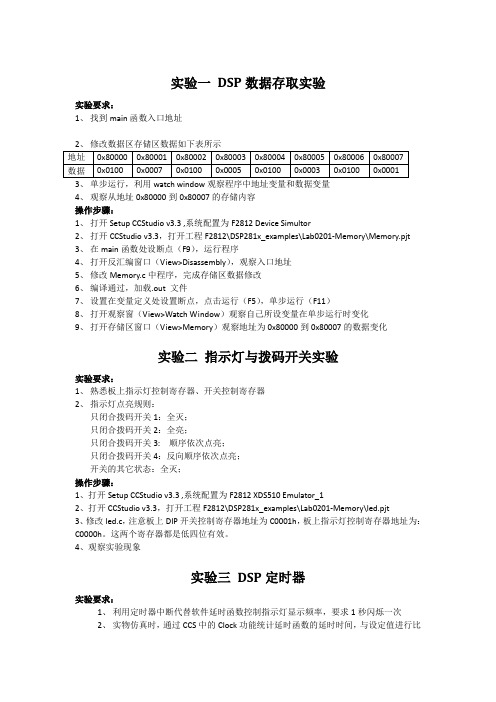
实验一DSP数据存取实验实验要求:1、找到main函数入口地址4、观察从地址0x80000到0x80007的存储内容操作步骤:1、打开Setup CCStudio v3.3 ,系统配置为F2812 Device Simultor2、打开CCStudio v3.3,打开工程F2812\DSP281x_examples\Lab0201-Memory\Memory.pjt3、在main函数处设断点(F9),运行程序4、打开反汇编窗口(View>Disassembly),观察入口地址5、修改Memory.c中程序,完成存储区数据修改6、编译通过,加载.out 文件7、设置在变量定义处设置断点,点击运行(F5),单步运行(F11)8、打开观察窗(View>Watch Window)观察自己所设变量在单步运行时变化9、打开存储区窗口(View>Memory)观察地址为0x80000到0x80007的数据变化实验二指示灯与拨码开关实验实验要求:1、熟悉板上指示灯控制寄存器、开关控制寄存器2、指示灯点亮规则:只闭合拨码开关1:全灭;只闭合拨码开关2:全亮;只闭合拨码开关3: 顺序依次点亮;只闭合拨码开关4:反向顺序依次点亮;开关的其它状态:全灭;操作步骤:1、打开Setup CCStudio v3.3 ,系统配置为F2812 XDS510 Emulator_12、打开CCStudio v3.3,打开工程F2812\DSP281x_examples\Lab0201-Memory\led.pjt3、修改led.c,注意板上DIP开关控制寄存器地址为C0001h,板上指示灯控制寄存器地址为:C0000h。
这两个寄存器都是低四位有效。
4、观察实验现象实验三DSP定时器实验要求:1、利用定时器中断代替软件延时函数控制指示灯显示频率,要求1秒闪烁一次2、实物仿真时,通过CCS中的Clock功能统计延时函数的延时时间,与设定值进行比较操作步骤:1、打开Setup CCStudio v3.3 ,系统配置为F2812 XDS510 Emulator_12、打开CCStudio v3.3,打开工程F2812\DSP281x_examples\Lab0201-Memory\time.pjt3、修改time.c程序,写一个由定时器中断产生的以1s为单位的延时函数void delay(int time);4、在菜单中选择profile>Enable\View5、在延时函数前后各设置一个断点6、清零时钟计数器(双击清零),点击Run运行程序7、计算时间t=测得值/150000000(假如系统的时钟工作在150MHZ),与设定值进行比较实验四事件管理器实验实验要求1、利用事件管理器中的16路中的PWM1,输出一段连续变化的PWM波2、驱动扬声器蜂鸣器播放一段音乐声(声音频率文件参考Speaker.pjt)操作步骤1、打开Setup CCStudio v3.3 ,系统配置为F2812 XDS510 Emulator_12、打开CCStudio v3.3,打开工程F2812\DSP281x_examples\Lab0201-Memory\PWM.pjt和F2812\DSP281x_examples\Lab0201-Memory\Speaker.pjt3、在例程Speaker.c中是使用通用定时器TIME0来连续输出频率的方波,这里要求改为用EVA中的PWM1代替之。
at32f421例程

at32f421例程
AT32F421是Atmel公司推出的一款基于ARM Cortex-M4架构的微控制器。
由于具体的例程会取决于您要实现的具体功能,因此我无法提供完整的AT32F421例程。
然而,我可以为您提供一个简单的AT32F421初始化例程,以便您开始使用该微控制器。
请注意,以下代码仅用于参考,并可能需要根据您的具体需求进行修改:
c
#include "at32f4xx.h"
void SystemClock_Config(void);
void Error_Handler(void);
void GPIO_Init(void);
int main(void)
{
HAL_Init();
SystemClock_Config();
GPIO_Init();
while (1)
{
// 在此处添加您的代码逻辑
}
}
void SystemClock_Config(void)
{
// 此处添加系统时钟配置代码
}
void GPIO_Init(void)
{
// 此处添加GPIO初始化代码
}
void Error_Handler(void)
{
while (1)
{
// 错误处理代码,例如LED闪烁或其他错误指示
}
}
这是一个基本的框架,您可以根据自己的需求添加适当的函数和逻辑。
如果您需要关于特定外设、功能或例程的更详细信息,建议您参考Atmel官方的
AT32F421数据手册和参考手册,或查找相关的开发社区和论坛以获取更多帮助。
windows void callback timerproc 传入参数-概述说明以及解释

windows void callback timerproc 传入参数-概述说明以及解释1.引言1.1 概述随着计算机技术的不断发展,定时器的应用变得越来越广泛,特别是在Windows系统中,定时器扮演着至关重要的角色。
在Windows系统中,使用定时器可以方便地实现各种定时任务,比如定时执行某个操作、定时更新界面等。
在使用定时器时,我们通常会用到回调函数来处理定时器到期时的事件。
回调函数可以是任意类型的函数,包括Void类型的回调函数。
Void 类型的回调函数在定时器到期时会被调用,用来执行特定的操作或任务。
在本文中,我们将重点介绍Windows系统中的定时器及其回调函数,以及Void Callback的概念和使用方法。
同时,我们还会深入探讨TimerProc函数的特点和传入参数,帮助读者更好地理解和应用定时器技术。
通过本文的学习,读者将能够更加熟练地运用定时器相关的知识,提高程序的效率和稳定性。
1.2 文章结构本文主要分为三个部分:引言、正文和结论。
- 引言部分包括对定时器的概述、本文结构的介绍以及研究目的的说明。
- 正文部分主要分为三个小节,分别介绍Windows中的定时器、Void Callback以及TimerProc函数相关内容。
- 在Windows中的定时器部分,将会探讨定时器的概述、实现机制以及定时器回调函数的作用。
- Void Callback部分将会详细讨论Void类型回调函数、Callback 函数的作用以及传入参数的相关内容。
- TimerProc函数部分将会介绍TimerProc函数的概述、使用方法以及传入参数的具体情况。
- 结论部分将对本文内容进行总结,探讨定时器的应用场景以及展望未来可能的发展方向。
1.3 目的本文的目的是探讨在Windows编程中使用定时器的相关知识,并重点讨论了Void Callback及TimerProc函数的使用方法和传入参数。
通过本文的学习,读者将能够深入了解Windows定时器的工作原理和使用技巧,提高对Windows编程的理解和应用能力。
KEYENCE 视觉系列 KV 系列 CPU 直连驱动器 1 系统配置指南说明书

KEYENCE CorporationVisual KV Series CPUDirect Driver1System Configuration (3)2Selection of External Device (4)3Example of Communication Setting (5)4Setup Items (6)5Cable Diagram (9)6Supported Devices (10)7Device Code and Address Code (12)8Error Messages (13)IntroductionThis manual describes how to connect the Display and the External Device (target PLC).In this manual, the connection procedure will be described by following the sections below:1System ConfigurationThis section shows the types of External Devices which can be connected and SIO type.)"1 System Configuration" (page 3)2Selection of External DeviceSelect the model (series) of the External Device to be connected and its connection method.)"2 Selection of External Device" (page 4)3Example of Communication Settings This section shows setting examples for communicating between the Display and the External Device.)"3 Example of Communication Setting" (page5)4Setup ItemsThis section describes communication setup items on the Display.Set the communication settings of the Display with GP-Pro EX or in off-line mode.)"4 Setup Items" (page 6)Operation5Cable DiagramThis section shows cables and adapters for connecting the Display and the External Device.)"5 Cable Diagram" (page 9)1System ConfigurationThe following shows the system configuration where the External Device of KEYENCE Corporation and the Display are connected.Connection Configuration•1:1 Connection•Simultaneous Port ConnectionSeriesCPU Link I/F SIO TypeSetting Example Cable Diagram Visual KV Series KV-10KV-16KV-24KV-40-RS232CSetting Example 1 (page 5)Cable Diagram 1 (page 9)•This driver cannot use IPC and PC/AT for Display.2Selection of External DeviceSelect the External Device to be connected to the Display.Setup Items Setup DescriptionMakerSelect the maker of the External Device to be connected. Select "KEYENCE Corporation".SeriesSelect the model (series) of the External Device to be connected and its connection method. Select "Visual KV Series CPU Direct".Check the External Device that can be connected in "Visual KV Series CPU Direct" in system configuration.)"1 System Configuration" (page 3)Use System AreaCheck this option to synchronize the system data area of the Display and the device (memory) of the External Device. When they are synchronized, you can use the ladder program of the External Device to switch the display or to display the window on the Display.Cf.GP Pro-EX Reference Manual "Appendix 1.4 LS Area (Direct AccessMethod)"This can also be set with GP-Pro EX or in off-line mode of the Display.Cf.GP Pro-EX Reference Manual " 5.17.6 Setting Guide of [System SettingWindow] [Main Unit Settings] Settings Guide System Area Setting"Cf.Maintenance/Troubleshooting "2.15.1 Settings common to all Displaymodels System Area Settings"PortSelect the port of the Display to be connected to the External Device.3Example of Communication SettingThe following shows examples of communication settings of the Display and the External Device, which are recommended by Pro-face.3.1Setting Example 1Settings of GP-Pro EXCommunication SettingsTo display the setting screen, select [Device/PLC Settings] from [System setting window] in workspace.Setting of External DeviceThe External Device does not require communication settings.Baud rate transmission speed is automatically changed within the range of "9600 to 57600" according to the setting on the Display.4Setup ItemsSet the communication settings of the Display with GP-Pro Ex or in off-line mode of the Display.The setting of each parameter must be identical to that of the External Device.)"3 Example of Communication Setting" (page 5)4.1Setup Items in GP-Pro EXCommunication SettingsTo display the setting screen, select [Device/PLC Settings] from [System setting window] in workspace.Setup Items Setup DescriptionSIO Type Select the SIO type for communicating with the External Device.Speed Select the communication speed between the External Device and the Display. Data Length Displays data length.Parity Displays how to check parity.Stop Bit Displays stop bit length.Flow Control Displays the communication control method to prevent overflow of transmission and reception data.Timeout Enter the time (s) for which the Display waits for the response from the External Device, from "1 to 127".Retry In case of no response from the External Device, enter how many times the Display retransmits the command, from "0 to 255".Wait To Send Enter the standby time (ms) from when the Display receives packets until it transmits the next command, from "0 to 255".RI/VCC You can switch RI/VCC of the 9th pin when you select RS232C for the SIO type.To connect to the IPC, you need to use the IPC selector switch to switch RI/5V. Please refer to the manual of the IPC for details.4.2Setup Items in Off-line ModeCommunication SettingsTo display the setting screen, touch [Device/PLC Settings] from [Peripheral Equipment Settings] in off-line mode. Touch the External Device you want to set from the list that appears.Cf.Maintenance/Troubleshooting Manual "2.2 Off-line Mode"Setup Items Setup DescriptionSIO Type Select the SIO type for communicating with the External Device.Speed Select the communication speed between the External Device and the Display.Data Length Displays data length.Parity Displays how to check parity.Stop Bit Displays stop bit length.Flow Control Displays the communication control method to prevent overflow of transmission and reception data.Timeout Enter the time (s) for which the Display waits for the response from the External Device, from "1 to 127".Retry In case of no response from the External Device, enter how many times the Display retransmits the command, from "0 to 255".Wait To SendEnter the standby time (ms) from when the Display receives packets until it transmits the next command, from "0 to 255".Option SettingsTo display the setting screen, touch [Device/PLC Settings] from [Peripheral Equipment Settings]. Touch the External Device you want to set from the list that appears, and touch [Option].Setup Items Setup DescriptionRI/VCCYou can switch RI/VCC of the 9th pin when you select RS232C for the SIO type.To connect to the IPC, you need to use the IPC selector switch to switch RI/5V . Please refer to the manual of the IPC for details.5Cable DiagramThe following cable diagram may be different from that recommended by KEYENCE Corporation. Please be assured, however, there is no operational problem in applying the cable diagram shown in this manual.•The FG pin on the External Device must be D-class grounded. Please refer to the manual of the External Device for details.•The SG and FG are connected inside the Display. If you connect the External Device to the SG, do not form any short-circuit loop in the system design.•If the communication is not stable due to noise or other factors, connect an isolation unit.Cable Diagram 1A.When using the conversion connector (OP-26486) and the connection cable (OP-26487) by KEYENCECorporationDisplay(Connection Port)CableRemarksGP (COM1)ST (COM1)A Conversion connector by KEYENCE CorporationOP-26486+Connection cable by KEYENCE CorporationOP-26487-6Supported DevicesThe following table shows the range of supported device addresses. Note that the actually supported range varies depending on the External Device to be used. Please check the actual range in the manual of your External Device.: This address can be specified as system data area.DeviceBit Address Word Address 32bitsRemarksI/O Relay00000 - 00915000 - 00907000 - 17915070 - 179Internal Auxiliary Relay01000 - 01915010 - 01903000 - 06915030 - 069Special Auxiliary Relay02000 - 02915020 - 029Timer (Contact)T000 - T249-----Counter (Contact)C000 - C249-----High-speed Counter Comparator (Contact)CTC0 - CTC3----- *1*1Write disableTimer (Current Value)-----TC000 - TC249Timer (Setting Value)-----TS000 - TS249Counter (Current Value)-----CC000 - CC249Counter (Setting Value)-----CS000 - CS249Data Memory -----DM0000 - DM1999Temporary Data Memory -----TM00 - TM31Digital Trimmer -----AT0 - AT1*1High-speed Counter (Current Value)-----CTH0 - CTH1High-speed Counter Comparator (Setting Value)-----CTC0 - CTC3•Please refer to the GP-Pro EX Reference Manual for system data area.Cf.GP-Pro EX Reference Manual "Appendix 1.4 LS Area (Direct Access Method)"•Please refer to the precautions on manual notation for icons in the table. )"Manual Symbols and Terminology"7Device Code and Address CodeUse device code and address code when you select "Device Type & Address" for the address type of the data display or other devices.DeviceDevice Name Device Code(HEX)Address CodeI/O Relay -----0080Word AddressInternal Auxiliary RelaySpecial Auxiliary RelayTimer (Current Value)TC 0060Word Address Timer (Setting Value)TS 0062Word Address Counter (Current Value)CC 0061Word Address Counter (Setting Value)CS 0063Word Address Data Memory DM 0000Word Address Temporary Data Memory TM 0001Word Address Digital Trimmer AT 0067Word Address High-speed Counter (Current Value)CTH0065Word AddressHigh-speed Counter Comparator (Setting Value)CTC 0066Word Address8Error MessagesError messages are displayed on the Display screen as follows: "No.: Device Name: Error Message (Error Occurrence Area)". Each description is shown below.Display Examples of Error Messages"RHAA035: PLC1: Error has been responded for device write command (Error Code: 2 [02H])"Error Code List of External DeviceError Code (HEX)Error Description04Accessed the device not defined as device in the External Device.*1 *1When you write to Timer (Contact/Current Value/Setting Value), Counter (Contact/Current Value/ Setting Value), High-speed Counter and High-speed Counter Comparator (Setting Value), the settingsin the ladder program is necessary in advance.。
%D2%BB%B8%F6TIMER0%B5%C4%C7%FD%B6%AF%B3%CC%D0%F2doc

一个TIMER0的驱动程序给刚做驱动的朋友一个,timer0的驱动程序,该驱动程序能够在gpb0口产生一个50khz的方波./* timer0.c* copyright (c) by tymanium from china* this is a device module file used for sbc2410* it can drive timer0, and in interrupt routine it will inverse gpb0 to generate tooth wav e. surely, it's very easy*//*usage:1. arm-linux-gcc -d__kernel__ -i/friendly-arm/kernel/include -dkbuild_badename=test -dmodu le -c -o timer0.o timer0.c2. start your sbc2410 evboard3. copy timer0.o to /lib4. in your board bash run # insmod /lib/timer0.o*/#include <linux/config.h>#include <linux/module.h>#include <linux/kernel.h>#include <linux/init.h>#include <linux/miscdevice.h>#include <linux/sched.h>#include <linux/delay.h>#include <linux/poll.h>#include <linux/spinlock.h>#include <linux/irq.h>#include <linux/delay.h>#include <asm/hardware.h>#define device_name "timer0_test" //#define ioport_major 200static unsigned char counter;static declare_wait_queue_head(timer0_wait);/*timer0 interrupt routine*/static void timer0_interrupt(int irq , void *dev_id, struct pt_regs *reg){if(irq !=irq_timer0){printk("bad irq % d in timer0 \n", irq);return;}cli();counter++;if(counter%2){write_gpio_bit(gpio_mode_out | gpio_b0, 1);}else{write_gpio_bit(gpio_mode_out | gpio_b0, 0);}wake_up_interruptible(&timer0_wait);}/*this function is called when you use insmod */static int __init timer0_init(void){int ret;counter=0;set_gpio_ctrl(gpio_b0 | gpio_pullup_en | gpio_mode_out); //set gpiob0 as general purpours e outtcfg0 &=0xffffff00;tcfg0 |=10; //set timer0 prescaler as 100tcfg1 &=0xfffffff0; //set timer0 divider as 2tcntb0=25; //here we can generate 10khz interrupt signalstcmpb0=12;tcon |=0x0e; //manually updata timer0ret=request_irq(irq_timer0,timer0_interrupt,sa_interrupt,device_name,null);if(ret){printk("s3c2410_timer0 : failed to register irq_timer0 (%d) \n",irq_timer0);return ret;}tcon &=0xfffffff8;tcon |=0x1; //start timer0return ret;}/*this function is called when you use rmmod*/static void __exit timer0_cleanup(void){free_irq(irq_timer0,timer0_interrupt);}module_init(timer0_init);module_exit(timer0_cleanup);module_license("gpl");。
MCC AVR ISO26262诊断库 v2.0.0 发布说明书

MCC AVR ISO26262 Diagnostic Library v2.0.0 ReleaseNotesWhat is the MCC AVR ISO26262 Diagnostic LibraryThe MPLAB® Code Configurator AVR ISO26262 Diagnostic Library is a suite of diagnostic tests implementing the diagnostics mechanisms described in the device's ISO 26262 functional safety manual. The library is distributedas an MPLAB® X MCC module, which allows for quick and easy configuration using graphical interfaces. MCC generates code for MPLAB® X and the MPLAB® XC8 compiler projects, based on the selections and configuration.Table of ContentsWhat is the MCC AVR ISO26262 Diagnostic Library (1)1.System Requirements (3)2.What's New? (4)3.Repairs and Enhancements (6)4.Known Issues (9)5.Supported Devices and Families (10)6.Revision History (11)The Microchip Website (12)Product Change Notification Service (12)Customer Support (12)Microchip Devices Code Protection Feature (12)Legal Notice (12)Trademarks (13)Quality Management System (13)Worldwide Sales and Service (14)System Requirements1. System Requirements1.MPLAB® X IDE v5.50 or later2.MCC v4.0.1 or later–MCC Core v5.0.0 or later3.MCC AVR® MCUs library v2.8.0 or later4.MPLAB® XC8 Compilers:–Recommended: TÜV SÜD Certified XC8 Functional Safety Compiler v2.29 or later2. What's New?•v2.0.0–Added support for AVR32DA and AVR64DA devices•AVR32DA28•AVR32DA32•AVR32DA48•AVR64DA28•AVR64DA32•AVR64DA48•AVR64DA64–Fix MISRA violations–Added the following diagnostic test for AVR-DA devices:•SW_CPU_SELF_TEST_LIB_01 - v1.0.0–Updates for the following diagnostic tests:•SW_CPU_REGISTER_TEST_01 - v1.0.2•SW_FLASH_MEMORY_CHECKSUM_CRC_TEST_01 - v1.0.2•SW_EEPROM_MEMORY_CHECKSUM_CRC_TEST_01 - v2.0.0•SW_SRAM_MARCH_TEST_01 - v1.0.1•SW_WATCHDOG_SIMPLE_TIMER_STARTUP_TEST - v1.1.0•SW_WATCHDOG_WINDOWED_TIMER_STARTUP_TEST - v1.1.0•SW_CLOCK_PERIODIC_MONITOR_01 - v1.0.1•SW_INTERRUPT_FREQUENCY_TEST_01 - v1.0.1–Deprecated the following diagnostic tests:•SW_CPU_REGISTER_RESET_STATE_CHECK_01 - v1.0.0–The new SRAM March test on AVR is destructive and must run first as outline by AoU-SRAM_MARCH_TEST-01 in the SRAM March test Assumptions of Use document. However,the cpu-reg-reset-state must also run first.–If cpu-reg-reset-state is run first, the result of the test is lost after the March test.–If the March test is run first, the cpu-reg-reset-state test will fail because not all CPU registers are 0x0.–It would be easiest to drop the cpu-reg-reset-state entirely to circumvent the issue.–Registers which were tested with cpu-reg-reset-state are already being tested with CPU Register Test and CPU Self Test.•SW_SRAM_MARCH_TEST_01 - March B and March C only–The March C algorithm has the exact same coverage as March C-, but with a longer executiontime.–March B is significantly more expensive in terms of test length and code size compared to March C- and does not fully cover all Linked Faults (LFs), while LFs are comparatively rare faults tooccur.–The ISO 26262 standard does not specify which March algorithm to implement, but mentions aset of fault models which are covered by March C-.–Various fixes and improvements (see 3. Repairs and Enhancements)•v1.2.0–Compatibility update with MCC Plugin v4.0.1 and MCC Core v5.0.1 (refer to MCC v4.0.1 Release Notes)–Renamed the library package–Added the following diagnostic tests:•SW_CLOCK_PERIODIC_MONITOR_01 - v1.0.0•SW_INTERRUPT_FREQUENCY_TEST_01 - v1.0.0–Updates, fixes, and improvements for the following diagnostic tests:•SW_CPU_REGISTER_TEST_01 - v1.0.1•SW_CPU_REGISTER_RESET_STATE_CHECK_01 - v1.0.0•SW_WATCHDOG_SIMPLE_TIMER_STARTUP_TEST - v1.0.2•SW_WATCHDOG_WINDOWED_TIMER_STARTUP_TEST - v1.0.2•SW_FLASH_MEMORY_CHECKSUM_CRC_TEST_01 - v1.0.1•SW_SRAM_MARCH_TEST_01 - v1.0.1•SW_EEPROM_MEMORY_CHECKSUM_CRC_TEST_01 - v1.0.1•v1.1.0–Added support for AVR128DAxx devices–Updates for the following diagnostic tests:•SW_WATCHDOG_SIMPLE_TIMER_STARTUP_TEST - v1.0.1•SW_WATCHDOG_WINDOWED_TIMER_STARTUP_TEST - v1.0.1•v1.0.0–Initial release with support for these Software Requirement IDs:•SW_CPU_REGISTER_TEST_01 - v1.0.0•SW_CPU_REGISTER_RESET_STATE_CHECK_01 - v1.0.0•SW_WATCHDOG_SIMPLE_TIMER_STARTUP_TEST - v1.0.0•SW_WATCHDOG_WINDOWED_TIMER_STARTUP_TEST - v1.0.0•SW_FLASH_MEMORY_CHECKSUM_CRC_TEST_01 - v1.0.0•SW_SRAM_MARCH_TEST_01 - v1.0.0•SW_EEPROM_MEMORY_CHECKSUM_CRC_TEST_01 - v1.0.03. Repairs and EnhancementsKnown Issues 4. Known IssuesSupported Devices and Families5. Supported Devices and Families•8-bit AVR Families–TinyAVR 1-series1•ATtiny2122•ATtiny2142•ATtiny4122•ATtiny4142•ATtiny4162•ATtiny4172•ATtiny814•ATtiny816•ATtiny817•ATtiny1614•ATtiny1616•ATtiny1617•ATtiny3216•ATtiny3217–AVR-DA•AVR32DA28•AVR32DA32•AVR32DA48•AVR64DA28•AVR64DA32•AVR64DA48•AVR64DA64•AVR128DA28•AVR128DA32•AVR128DA48•AVR128DA64Notes:1.These devices currently do not support SW_CPU_SELF_TEST_LIB_012.These devices have limited memory. Enabling multiple tests may result to a compilation error.Revision History 6. Revision HistoryThe Microchip WebsiteMicrochip provides online support via our website at /. This website is used to make files and information easily available to customers. Some of the content available includes:•Product Support – Data sheets and errata, application notes and sample programs, design resources, user’s guides and hardware support documents, latest software releases and archived software•General Technical Support – Frequently Asked Questions (FAQs), technical support requests, online discussion groups, Microchip design partner program member listing•Business of Microchip – Product selector and ordering guides, latest Microchip press releases, listing of seminars and events, listings of Microchip sales offices, distributors and factory representativesProduct Change Notification ServiceMicrochip’s product change notification service helps keep customers current on Microchip products. Subscribers will receive email notification whenever there are changes, updates, revisions or errata related to a specified product family or development tool of interest.To register, go to /pcn and follow the registration instructions.Customer SupportUsers of Microchip products can receive assistance through several channels:•Distributor or Representative•Local Sales Office•Embedded Solutions Engineer (ESE)•Technical SupportCustomers should contact their distributor, representative or ESE for support. Local sales offices are also available to help customers. A listing of sales offices and locations is included in this document.Technical support is available through the website at: /supportMicrochip Devices Code Protection FeatureNote the following details of the code protection feature on Microchip devices:•Microchip products meet the specification contained in their particular Microchip Data Sheet.•Microchip believes that its family of products is one of the most secure families of its kind on the market today, when used in the intended manner and under normal conditions.•There are dishonest and possibly illegal methods used to breach the code protection feature. All of these methods, to our knowledge, require using the Microchip products in a manner outside the operating specifications contained in Microchip’s Data Sheets. Most likely, the person doing so is engaged in theft of intellectual property.•Microchip is willing to work with the customer who is concerned about the integrity of their code.•Neither Microchip nor any other semiconductor manufacturer can guarantee the security of their code. Code protection does not mean that we are guaranteeing the product as “unbreakable.”Code protection is constantly evolving. We at Microchip are committed to continuously improving the code protection features of our products. Attempts to break Microchip’s code protection feature may be a violation of the Digital Millennium Copyright Act. If such acts allow unauthorized access to your software or other copyrighted work, you may have a right to sue for relief under that Act.Legal NoticeInformation contained in this publication regarding device applications and the like is provided only for your convenience and may be superseded by updates. It is your responsibility to ensure that your application meets withyour specifications. MICROCHIP MAKES NO REPRESENTATIONS OR WARRANTIES OF ANY KIND WHETHER EXPRESS OR IMPLIED, WRITTEN OR ORAL, STATUTORY OR OTHERWISE, RELATED TO THE INFORMATION, INCLUDING BUT NOT LIMITED TO ITS CONDITION, QUALITY, PERFORMANCE, MERCHANTABILITY OR FITNESS FOR PURPOSE. Microchip disclaims all liability arising from this information and its use. Use of Microchip devices in life support and/or safety applications is entirely at the buyer’s risk, and the buyer agrees to defend, indemnify and hold harmless Microchip from any and all damages, claims, suits, or expenses resulting from such use. No licenses are conveyed, implicitly or otherwise, under any Microchip intellectual property rights unless otherwise stated.TrademarksThe Microchip name and logo, the Microchip logo, Adaptec, AnyRate, AVR, AVR logo, AVR Freaks, BesTime, BitCloud, chipKIT, chipKIT logo, CryptoMemory, CryptoRF, dsPIC, FlashFlex, flexPWR, HELDO, IGLOO, JukeBlox, KeeLoq, Kleer, LANCheck, LinkMD, maXStylus, maXTouch, MediaLB, megaAVR, Microsemi, Microsemi logo, MOST, MOST logo, MPLAB, OptoLyzer, PackeTime, PIC, picoPower, PICSTART, PIC32 logo, PolarFire, Prochip Designer, QTouch, SAM-BA, SenGenuity, SpyNIC, SST, SST Logo, SuperFlash, Symmetricom, SyncServer, Tachyon, TempTrackr, TimeSource, tinyAVR, UNI/O, Vectron, and XMEGA are registered trademarks of Microchip Technology Incorporated in the U.S.A. and other countries.APT, ClockWorks, The Embedded Control Solutions Company, EtherSynch, FlashTec, Hyper Speed Control, HyperLight Load, IntelliMOS, Libero, motorBench, mTouch, Powermite 3, Precision Edge, ProASIC, ProASIC Plus, ProASIC Plus logo, Quiet-Wire, SmartFusion, SyncWorld, Temux, TimeCesium, TimeHub, TimePictra, TimeProvider, Vite, WinPath, and ZL are registered trademarks of Microchip Technology Incorporated in the U.S.A.Adjacent Key Suppression, AKS, Analog-for-the-Digital Age, Any Capacitor, AnyIn, AnyOut, BlueSky,BodyCom, CodeGuard, CryptoAuthentication, CryptoAutomotive, CryptoCompanion, CryptoController, dsPICDEM, , Dynamic Average Matching, DAM, ECAN, EtherGREEN, In-Circuit Serial Programming, ICSP, INICnet, Inter-Chip Connectivity, JitterBlocker, KleerNet, KleerNet logo, memBrain, Mindi, MiWi, MPASM,MPF, MPLAB Certified logo, MPLIB, MPLINK, MultiTRAK, NetDetach, Omniscient Code Generation, PICDEM, , PICkit, PICtail, PowerSmart, PureSilicon, QMatrix, REAL ICE, Ripple Blocker, SAM-ICE, SerialQuad I/O, SMART-I.S., SQI, SuperSwitcher, SuperSwitcher II, Total Endurance, TSHARC, USBCheck, VariSense, ViewSpan, WiperLock, Wireless DNA, and ZENA are trademarks of Microchip Technology Incorporated in the U.S.A. and other countries.SQTP is a service mark of Microchip Technology Incorporated in the U.S.A.The Adaptec logo, Frequency on Demand, Silicon Storage Technology, and Symmcom are registered trademarks of Microchip Technology Inc. in other countries.GestIC is a registered trademark of Microchip Technology Germany II GmbH & Co. KG, a subsidiary of Microchip Technology Inc., in other countries.All other trademarks mentioned herein are property of their respective companies.© 2020, Microchip Technology Incorporated, Printed in the U.S.A., All Rights Reserved.ISBN:Quality Management SystemFor information regarding Microchip’s Quality Management Systems, please visit /quality.Worldwide Sales and Service。
总结tim_itconfig函数配置流程,逐条解释代码意思

总结tim_itconfig函数配置流程,逐条解释代码意思标题: 总结tim_itconfig函数配置流程,逐条解释代码意思正文:在嵌入式系统中,定时器是常用的硬件模块,它可以用来产生精确的定时中断。
由于定时器的配置过程较为复杂,通常会提供一个配置函数来简化配置流程。
tim_itconfig函数就是这样一个配置定时器中断的函数。
下面将逐条解释代码的意思。
1. TIM_TypeDef *TIMx: 定义了一个指针TIMx,用于指向定时器的基地址。
TIM_TypeDef是一个结构体类型,它定义了定时器寄存器的地址偏移量。
2. uint16_t TIM_IT: 定义了一个16位的无符号整型变量TIM_IT,用于表示定时器中断的类型。
其中每个比特位对应一个中断类型,可以通过位掩码的方式来设置多个中断类型。
3. FunctionalState NewState: 定义了一个枚举类型变量NewState,用于表示定时器中断的使能状态。
该枚举类型有两个取值:ENABLE和DISABLE,分别表示使能和禁止。
4. assert_param(IS_TIM_ALL_PERIPH(TIMx)): 这是一个宏定义,在编译时会进行参数的合法性检查。
如果TIMx不是一个合法的定时器基地址,编译器会报错。
5. assert_param(IS_TIM_IT(TIM_IT)): 这是一个宏定义,在编译时会进行参数的合法性检查。
如果TIM_IT不是一个合法的定时器中断类型,编译器会报错。
6. assert_param(IS_FUNCTIONAL_STATE(NewState)): 这是一个宏定义,在编译时会进行参数的合法性检查。
如果NewState不是一个合法的枚举值,编译器会报错。
7. if (NewState != DISABLE):判断NewState是否为DISABLE,如果不是,则进入if语句。
8. TIMx->DIER |= TIM_IT:将TIM_IT设置到定时器的中断使能寄存器DIER中。
实验三使用中断的定时器

实验三使用中断的定时器一、实验目的1、理解C2000芯片的CPU定时器和中断系统的工作原理;2、学会使用TMS320F28027芯片的定时器实现定时;3、掌握CPU定时器和PIE外设中断控制器相关寄存器的配置与使用。
二、概述本实验的程序实现了定时器Timer0定时1秒,对应LED灯D10状态翻转,由亮到灭,在由灭到亮,一致循环下去;定时器Timer1定时2秒,对应LED灯D12状态翻转;定时器Timer2定时4秒,对应LED灯D13状态翻转。
表1 输出引脚硬件配置表3D13GPIO237Timer2对应LED图1 LED灯连接电路图三、实验内容1、按照新建工程项目的方法进行实验(参考实验二)。
2、主函数(程序流程框图见图2所示)#include"DSP28x_Project.h"// Device Headerfile and Examples Include File // Prototype statements for functions found within this file.interrupt void cpu_timer0_isr(void);interrupt void cpu_timer1_isr(void);interrupt void cpu_timer2_isr(void);void InitTimerGpio(void);void main(void){// Step 1.系统初始化Initialize System Control:// PLL, WatchDog, enable Peripheral Clocks// This example function is found in the f2802x_SysCtrl.c file.InitSysCtrl();// Step 2.GPIO初始化 Initalize GPIO:// This example function is found in the f2802x_Gpio.c file and// illustrates how to set the GPIO to it's default state.// InitGpio(); // Skipped for this exampleInitTimerGpio();// Step 3. 清除(关闭)中断并初始化外设中断向量表 Clear all interrupts and initialize PIE vector table:// 关闭CPU中断 Disable CPU interruptsDINT;// Initialize the PIE control registers to their default state.// The default state is all PIE interrupts disabled and flags// are cleared.// This function is found in the f2802x_PieCtrl.c file.InitPieCtrl();// Disable CPU interrupts and clear all CPU interrupt flags:IER = 0x0000;IFR = 0x0000;// Initialize the PIE vector table with pointers to the shell Interrupt// Service Routines (ISR).// This will populate the entire table, even if the interrupt// is not used in this example. This is useful for debug purposes.// The shell ISR routines are found in f2802x_DefaultIsr.c.// This function is found in f2802x_PieVect.c.InitPieVectTable();// Interrupts that are used in this example are re-mapped to// 设置中断向量表 ISR functions found within this file.EALLOW; // This is needed to write to EALLOW protected registers0 = &cpu_timer0_isr;1 = &cpu_timer1_isr;2 = &cpu_timer2_isr;EDIS; // This is needed to disable write to EALLOW protected registers // Step 4. 初始化CPU定时器 Initialize the Device Peripheral. This function can be// found in f2802x_CpuTimers.cInitCpuTimers(); // For this example, only initialize the Cpu Timers#if (CPU_FRQ_60MHZ)//配置CPU定时器 Configure CPU-Timer 0, 1, and 2 to interrupt every second:// 60MHz CPU Freq, 1 second Period (in uSeconds)ConfigCpuTimer(&CpuTimer0, 60, );ConfigCpuTimer(&CpuTimer1, 60, );ConfigCpuTimer(&CpuTimer2, 60, );#endif#if (CPU_FRQ_50MHZ)// Configure CPU-Timer 0, 1, and 2 to interrupt every second:// 50MHz CPU Freq, 1 second Period (in uSeconds)ConfigCpuTimer(&CpuTimer0, 50, );ConfigCpuTimer(&CpuTimer1, 50, );ConfigCpuTimer(&CpuTimer2, 50, );#endif#if (CPU_FRQ_40MHZ)// Configure CPU-Timer 0, 1, and 2 to interrupt every second:// 40MHz CPU Freq, 1 second Period (in uSeconds)ConfigCpuTimer(&CpuTimer0, 40, );ConfigCpuTimer(&CpuTimer1, 40, );ConfigCpuTimer(&CpuTimer2, 40, );#endif// To ensure precise timing, use write-only instructions to write to the entire register. Therefore, if any// of the configuration bits are changed in ConfigCpuTimer and InitCpuTimers (in F2802x_CpuTimers.h), the// below settings must also be updated..all = 0x4001; //Use write-only instruction to set TSS bit = 0.all = 0x4001; // Use write-only instruction to set TSS bit = 0.all = 0x4001; // Use write-only instruction to set TSS bit = 0// Step 5.使能用到的中断 User specific code, enable interrupts:// Enable CPU int1 which is connected to CPU-Timer 0, CPU int13// which is connected to CPU-Timer 1, and CPU int 14, which is connected// to CPU-Timer 2:IER |= M_INT1;IER |= M_INT13;IER |= M_INT14;// Enable TINT0 in the PIE: Group 1 interrupt 7R1.7 = 1;// Enable global Interrupts and higher priority real-time debug events:EINT; // Enable Global interrupt INTMERTM; // Enable Global realtime interrupt DBGM// Step 6. 设置空循环(程序进入运行状态) IDLE loop. Just sit and loop forever (optional):for(;;);}//下面是中断服务程序interrupt void cpu_timer0_isr(void){ EALLOW;ruptCount++;.GPIO0 = 1;.GPIO34 = 1;// Acknowledge this interrupt to receive more interrupts from group 1 K.all = PIEACK_GROUP1;}interrupt void cpu_timer1_isr(void){ EALLOW;ruptCount++;.GPIO1 = 1;// The CPU acknowledges the interrupt.EDIS;}interrupt void cpu_timer2_isr(void){ EALLOW;ruptCount++;.GPIO2 = 1;// The CPU acknowledges the interrupt.EDIS;}// 下面是配置GPIOvoid InitTimerGpio(void){EALLOW;X1.34 = 0;R.34 = 1;X1.0 = 0;R.0 = 1;X1.1 = 0;R.1 = 1;X1.2 = 0;R.2 = 1;EDIS;}四、课外学习任务1、进一步理解实验内容,在实验板上找到GPIO34连接的LED灯,试解读下面的程序代码:X1.34 = 0;R.34 = 1;2、总结实验内容及步骤写出实验报告。
DSP28335—cpu time0
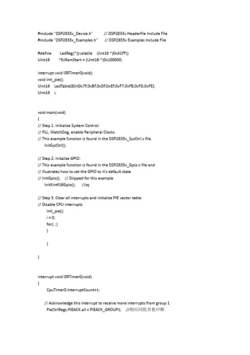
CpuTimer0Regs.TCR.bit.TIF=1; //清除定时器的中断标志位(即:手动清除外设的中断标志位)
CpuTimer0Regs.TCR.bit.TRB=1; //定时器重新转载位数
LedReg = LedTable[i];
InitSysCtrl();
// Step 2. Initalize GPIO:
// This example function is found in the DSP2833x_Gpio.c file and
// illustrates how to set the GPIO to it's default state.
InitPieVectTable(); //初始化PIE中断向量表(这里面使能了PIE向量表) ENPIE=1;
// InitPeripherals(); //初始化外设中断模块(这里是CPU定时器0模块的初始化)
EALLOW; //用于保护寄存器
PieVectTable.TINT0 = &ISRTimer0;
#defineLedReg(*((volatile Uint16 *)0x41FF))
Uint16 *ExRamStart = (Uint16 *)0x100000;
interrupt void ISRTimer0(void);
void init_pie();
Uint16 LedTable[8]={0x7F,0xBF,0xDF,0xEF,0xF7,0xFB,0xFD,0xFE};
// InitGpio(); // Skipped for this example
ConfigCpuTimer()函数
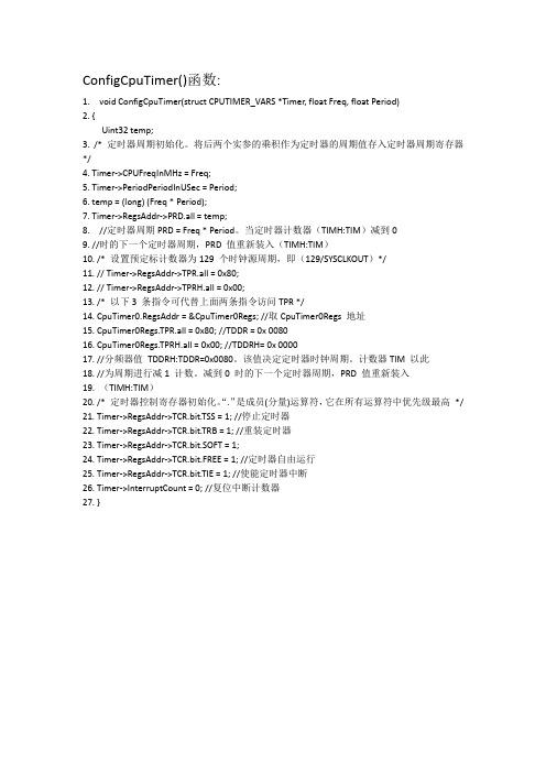
ConfigCpuTimer()函数:1. void ConfigCpuTimer(struct CPUTIMER_VARS *Timer, float Freq, float Period)2. {Uint32 temp;3. /* 定时器周期初始化。
将后两个实参的乘积作为定时器的周期值存入定时器周期寄存器*/4. Timer->CPUFreqInMHz = Freq;5. Timer->PeriodPeriodInUSec = Period;6. temp = (long) (Freq * Period);7. Timer->RegsAddr->PRD.all = temp;8. //定时器周期PRD = Freq * Period。
当定时器计数器(TIMH:TIM)减到09. //时的下一个定时器周期,PRD 值重新装入(TIMH:TIM)10. /* 设置预定标计数器为129 个时钟源周期,即(129/SYSCLKOUT)*/11. // Timer->RegsAddr->TPR.all = 0x80;12. // Timer->RegsAddr->TPRH.all = 0x00;13. /* 以下3 条指令可代替上面两条指令访问TPR */14. CpuTimer0.RegsAddr = &CpuTimer0Regs; //取CpuTimer0Regs 地址15. CpuTimer0Regs.TPR.all = 0x80; //TDDR = 0x 008016. CpuTimer0Regs.TPRH.all = 0x00; //TDDRH= 0x 000017. //分频器值TDDRH:TDDR=0x0080。
该值决定定时器时钟周期。
计数器TIM 以此18. //为周期进行减1 计数。
减到0 时的下一个定时器周期,PRD 值重新装入19. (TIMH:TIM)20. /* 定时器控制寄存器初始化。
最具参考价值的程序例程TMS320F28xx(黄书程序电子版)
第3章TMS320X28xx处理器及其应用例1、初始化锁相环及外设时钟函数//--------------------------------------------------------------------------------------------------------------------- // 初始化锁相环及外设时钟函数: InitPll://--------------------------------------------------------------------------------------------------------------------- void InitPll(Uint16 val){volatile Uint16 iV ol;if (SysCtrlRegs.PLLCR.bit.DIV != val){EALLOW;SysCtrlRegs.PLLCR.bit.DIV = val;EDIS;// 在锁相环时钟频率切换过程中,只有当锁相环稳定后CPU才会切换到新的PLL设置。
因此在设置完PLLCR后需要等待PLL稳定。
PLL的切换时间大约等于131072个输入时钟周期。
DisableDog();for(iVol= 0; iV ol< ( (131072/2)/12 ); iVol++){}}}// 为降低系统功耗,不使用的外设时钟需要屏蔽。
// 但如果使用外设必须首先使能相应的外设时钟。
void InitPeripheralClocks(void){EALLOW;// HISPCP/LOSPCP预定表寄存器设置SysCtrlRegs.HISPCP.all = 0x0001;SysCtrlRegs.LOSPCP.all = 0x0002;// 使能使用的外设时钟SysCtrlRegs.PCLKCR.bit.EV AENCLK=1;SysCtrlRegs.PCLKCR.bit.EVBENCLK=1;SysCtrlRegs.PCLKCR.bit.SCIAENCLK=1;SysCtrlRegs.PCLKCR.bit.SCIBENCLK=1;SysCtrlRegs.PCLKCR.bit.MCBSPENCLK=1;SysCtrlRegs.PCLKCR.bit.SPIENCLK=1;SysCtrlRegs.PCLKCR.bit.ECANENCLK=1;SysCtrlRegs.PCLKCR.bit.ADCENCLK=1;EDIS;}例2、.cmd格式文件举例MEMORY{PAGE 0 :/* 本例中H0分成PAGE 0和PAGE 1 *//* BEGIN is used for the "boot to HO" bootloader mode *//* 如果从XINTF Zone 7空间boot,RESET装载复位向量,*//* 其他复位矢量从BOOTROM中装载*/RAMM0 :origin = 0x000000,length = 0x000400BEGIN :origin = 0x3F8000,length = 0x000002PRAMH0 :origin = 0x3F8002,length = 0x0014FEBOOTROM :origin = 0x3FF000,length = 0x000FC0RESET :origin = 0x3FFFC0,length = 0x000002PAGE 1 :RAMM1 :origin = 0x000400,length = 0x000400L0L1RAM :origin = 0x008000,length = 0x002000DRAMH0 :origin = 0x3f9500,length = 0x000B00}SECTIONS{/* 设置"boot to H0"模式:代码起始段(DSP281x_CodeStartBranch.asm)*//* 然后重新定位用户代码开始入口。
sched_setaffinity 用法

sched_setaffinity 用法sched_setaffinity 是一个函数,其用法如下:```cint sched_setaffinity(pid_t pid, size_t cpusetsize, const cpu_set_t *mask);```参数解释:- pid:要设置 CPU 亲和力的进程的进程 ID。
传入 0 表示设置当前进程的 CPU 亲和力。
- cpusetsize:传入 cpu_set_t 数据结构的大小。
- mask:一个 cpu_set_t 结构,用于设置 CPU 亲和力。
返回值:- 成功:0- 失败:-1,错误代码存储在 errno 中。
该函数用于设置进程的 CPU 亲和力,即限制进程运行在特定的 CPU 上。
传入的 mask 参数是一个位掩码,每一位对应一个 CPU 核心。
调用该函数后,进程将只能在 mask 所指定的CPU 上运行。
注意,某些权限如 root 等可能会影响调用 sched_setaffinity 的行为。
在某些系统上,也可能需要 CAP_SYS_NICE 权限来调用该函数。
以下是此函数的一个示例用法:```c#include <stdio.h>#include <unistd.h>#include <errno.h>#include <sched.h>int main() {cpu_set_t set;CPU_ZERO(&set); // 清空 cpu_set_t 结构// 设置 CPU 亲和力,将进程限制在 CPU 0 和 CPU 1 上运行 CPU_SET(0, &set);CPU_SET(1, &set);int ret = sched_setaffinity(0, sizeof(cpu_set_t), &set);if (ret == -1) {perror("sched_setaffinity");return 1;}// 打印当前进程的 CPU 亲和力cpu_set_t get;ret = sched_getaffinity(0, sizeof(cpu_set_t), &get);if (ret == -1) {perror("sched_getaffinity");return 1;}printf("current CPU affinity: ");for (int i = 0; i < CPU_SETSIZE; i++) {if (CPU_ISSET(i, &get)) {printf("%d ", i);}}printf("\n");return 0;}```在上述示例中,CPU_ZERO 用于清空 cpu_set_t 结构,CPU_SET 用于设置 CPU 亲和力。
dsp实验报告
DSP实验报告院系名称电气与信息工程学院专业名称电气工程及其自动化班级电气1002班学生姓名苏美龙学号 10401700403 指导老师易吉良2013年11 月 6 日实验一拨码开关实验—、实验目的1.了解DSP开发系统的组成和结构2.了解IO 的基本编程方法二、实验设备计算机,CCS3.1版本软件,DSP 仿真器,E300 实验箱,2812CPU板(新的)三、实验原理8位的数字量输入(由拨码开关产生),当拨码打到靠近LED时为低。
相反为高。
通过74LS244(可读)缓冲连接到DSP 的数据总线的低8 位。
CPU 通过读指令读取到拨码开关产生的8 位输出的数字量,然后CPU通过写指令把读出的8 位数字量写入(0x0200)单元内,使连接到DSP的数据总线的低8 位的74LS273的输出端产生高低信号,此时LED 灯产生亮灭。
当对应LED 灯点亮时说明输出为低,熄灭时为高。
(器件74LS244和74LS273详细的介绍请参看数据手册)。
数字量输入输出单元的资源分配如下:基地址:0000h(当CS0为0时分配有效)数字量分配空间为数据空间地址:基地址+0x200(低8位,只读)拨码开关扩展工作原理说明:74LS244 片选号、74LS273 片选信号和74LS273 复位信号由E300 上CPLD 译码产生。
本实验使用DSP 数据总线的低8位。
本实验的程序流程框图如下:四、实验步骤1. 2812CPU板上的JUMP1的1和2脚短接,拨码开关SW1的第二位置ON。
2.E300 板上的开关SW4 的第一位置ON,其余OFF;SW5开关全部置ON;其余开关全部置OFF。
3. 运行Code Composer Studio (CCS)(ccs3.1需要“DEBUG→Connect”)4. 用“Project\Open”打开系统项目文件\e300.test \normal\DSP2801x_example\e300_02_swich\ Exampla_281_swich.pjt;5. 编译全部文件并装载\normal\DSP2801x_example\e300_02_swich\Exampla_281_swich.out;6. 单击“Debug \Go Main”跳到主程序的开始;7. 单击“Debug \RUN”运行程序8.任意拨动E300 底板上的拨动开关,观察LED和拨动开关的对应情况。
定时器0寄存器CpuTimer0Regs

CpuTimer0Regs.TPR.all = 0xFFFF;//预定标寄存器CpuTimer0Regs.TPRH.all = 0;这两句话其实是给一样的寄存器来赋值的,因为CPU定时器0的预定标计数器的寄存器是由两个构成的,一个是TPRH,一个是TPR,所以上述的两个语句中是否有一个是TPRH。
好,抛开这个问题不谈,我们来简单谈一下CPU定时器0各个寄存器之间的关系。
CPU定时器有寄存器:计数器寄存器TIMH:TIM,周期寄存器PRDH:PRD,控制寄存器TCR,预定标计数器TPRH:TPR。
这里,AH:A的形式表示是一个32位的寄存器是由两个16位的寄存器构成的,AH是高16位,A是低16位。
CPU定时器计数方式是复位时,计数器寄存器TIMH:TIM内装载周期寄存器PRDH:PRD的值,经历一个计数器时钟时,TIMH:TIM内的值就减1,一直减到0,这时产生定时器周期中断事件,并重新装载PRDH:PRD的值,开始计数。
这里就讲到了,计数器寄存器在一个计数器时钟时减1,那么计数器时钟是多少呢?或者说是每隔多少时间,定时器的计数器才会减1呢?这个就由预定标寄存器TPRH:TPR来决定了。
先来了解一下预定标寄存器的结构了,TPRH和TPR这两个寄存器都由两部分构成,高8位为定时器预定标计数器PSC,低8位是定时器分频TDDR。
也就是说,TPRH是由PSCH和TDDRH 构成,而TPR是由PSC和TDDR构成的。
这个工作的原理其实和前面的定时器计数类似的,复位时,PSCH:PSC重新装载TDDRH:TDDR的值,然后经历一个CPU时钟时,PSCH:PSC就减1,PSCH:PSC的值减为0时,重新装载TDDRH:TDDR的值,并且产生一个计数器时钟,TIMH:TIM的值减1。
如果你在System中的系统时钟倍频后设置为150M的话,Cputimer0定时时间可以这样理解ConfigCpuTimer(&CpuTimer2, 75, 1000000)中定时频率为75MHZ(即:1个计时周期计75M个系统时钟), 计时周期为1000000,系统时钟频率150M则定时时间这样计算(1/150M)*75MHZ*1000000=500000us(M对应us)=0.5s现在的学习板大多数采用30M的晶振,则当系统时钟(SYSCLKOUT)为150M时,定时一秒中断的程序为ConfigCpuTimer(&CpuTimer0, 150, 1000000)。
- 1、下载文档前请自行甄别文档内容的完整性,平台不提供额外的编辑、内容补充、找答案等附加服务。
- 2、"仅部分预览"的文档,不可在线预览部分如存在完整性等问题,可反馈申请退款(可完整预览的文档不适用该条件!)。
- 3、如文档侵犯您的权益,请联系客服反馈,我们会尽快为您处理(人工客服工作时间:9:00-18:30)。
// TI File $Revision: /main/3 $
// Checkin $Date: July 2, 2007 11:33:22 $
//########################################################################### //
// FILE: Example_281xCpuTimer.c
//
// TITLE: DSP281x Device Getting Started Program.
//
// ASSUMPTIONS:
//
// This program requires the DSP281x V1.00 header files.
// As supplied, this project is configured for "boot to H0" operation.
//
// Other then boot mode configuration, no other hardware configuration
// is required.
//
// DESCRIPTION:
//
// This example configures CPU Timer0 and increments
// a counter each time the timer asserts an interrupt.
//
// Watch Variables:
// CpuTimer0.InterruptCount
//
//########################################################################### // $TI Release: DSP281x C/C++ Header Files V1.20 $
// $Release Date: July 27, 2009 $
//###########################################################################
#include "DSP281x_Device.h" // DSP281x Headerfile Include File
#include "DSP281x_Examples.h" // DSP281x Examples Include File
// Prototype statements for functions found within this file.
interrupt void cpu_timer0_isr(void);
void main(void)
{
// Step 1. Initialize System Control:
// PLL, WatchDog, enable Peripheral Clocks
// This example function is found in the DSP281x_SysCtrl.c file.
InitSysCtrl();
// Step 2. Initalize GPIO:
// This example function is found in the DSP281x_Gpio.c file and
// illustrates how to set the GPIO to it's default state.
// InitGpio(); // Skipped for this example
// Step 3. Clear all interrupts and initialize PIE vector table:
// Disable CPU interrupts
DINT;
// Initialize the PIE control registers to their default state.
// The default state is all PIE interrupts disabled and flags
// are cleared.
// This function is found in the DSP281x_PieCtrl.c file.
InitPieCtrl();
// Disable CPU interrupts and clear all CPU interrupt flags:
IER = 0x0000;
IFR = 0x0000;
// Initialize the PIE vector table with pointers to the shell Interrupt
// Service Routines (ISR).
// This will populate the entire table, even if the interrupt
// is not used in this example. This is useful for debug purposes.
// The shell ISR routines are found in DSP281x_DefaultIsr.c.
// This function is found in DSP281x_PieVect.c.
InitPieVectTable();
// Interrupts that are used in this example are re-mapped to
// ISR functions found within this file.
EALLOW; // This is needed to write to EALLOW protected registers
PieV ectTable.TINT0 = &cpu_timer0_isr;
EDIS; // This is needed to disable write to EALLOW protected registers
// Step 4. Initialize all the Device Peripherals:
// This function is found in DSP281x_InitPeripherals.c
// InitPeripherals(); // Not required for this example
InitCpuTimers(); // For this example, only initialize the Cpu Timers
// Configure CPU-Timer 0 to interrupt every second:
// 100MHz CPU Freq, 1 second Period (in uSeconds)
ConfigCpuTimer(&CpuTimer0, 100, 1000000);
StartCpuTimer0();
// Step 5. User specific code, enable interrupts:
// Enable CPU INT1 which is connected to CPU-Timer 0:
IER |= M_INT1;
// Enable TINT0 in the PIE: Group 1 interrupt 7
PieCtrlRegs.PIEIER1.bit.INTx7 = 1;
// Enable global Interrupts and higher priority real-time debug events:
EINT; // Enable Global interrupt INTM
ERTM; // Enable Global realtime interrupt DBGM
// Step 6. IDLE loop. Just sit and loop forever (optional):
for(;;);
}
interrupt void cpu_timer0_isr(void)
{
CpuTimer0.InterruptCount++;
// Acknowledge this interrupt to receive more interrupts from group 1
PieCtrlRegs.PIEACK.all = PIEACK_GROUP1;
}
//===================================================================== ======
// No more.
//===================================================================== ======。
