荣誉EL 宽温长寿命贴片铝电解电容规格书
荣誉HU中高压贴片铝电解电容规格书

Size Part No. D×L
12.5×13.5 12.5×13.5 16×16.5 16×21.5
R.V. (V.DC)
Cap. ( μ F)
TLeakage Current ( μA ) max.
241 311 401 535
Ripple Current (mA ms.) (120Hz,105℃) max.
3.3~68 μF
静电容量允许偏差Capacitance Tolerance ±20% at 120 Hz, 20 漏电流
After 2 minutes application of rated voltage,leakage current is not more than 0.04CV+100(μΑ) 施加额定工作电压2分钟,LC≤0.04CV+100(μΑ) Measurement frequency 测试频率: 120Hz,Temperature 温度:20℃ 160 0.15 200 0.15 250 0.15 400 0.20 450 0.20 Rated voltage(V.DC) 额定工作电压 Tan
Leakage Current 漏电流 Initial specified value or less 不大于规范值
高温储存特性 Shelf Life
After leaving capacitors under no load at 105℃ for 1000 hours, they meet the specified value for load life characteristics listed above. 在105℃环境中无负荷放置1000小时后,电容器的特性符合高温负荷特性中所列的规定值。
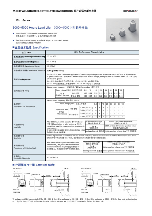
荣誉KL 5000小时长寿命贴片铝电解电容规格书
Ripple Current (mA ms) at 105℃ 120Hz
KL
规格尺寸及最大允许纹波电流 Standard size & Maximum permissible ripple current
容量 Cap(uF)
0.1 0.22 0.33 0.47 1 22 3.3 4.7 10 22 33 47 68 100 150 220 330 470 680 1000 2200
KL
(mm)
DXL A B C E±0.2 L Φ4X5.8 1.8 4.3 4.3 1.0 5.8 Φ5X8 2.1 5.3 5.3 1.3 5.8 Φ6.3X5.8 / 7.7 2.4 6.6 6.6 2.2 5.8 / 7.7 Φ8X6.2 3.3 8.3 8.3 2.2 6.2 Φ8X10.5 Φ10X10.5 / 13.5 2.9 8.3 8.3 3.1 10.5 4.7 13.0 13.0 4.4 10.5 / 13.5 Φ12.5X13.5 / 16 4.7 13.0 13.0 4.4 13.5 / 16 Φ16X16.5 / 21.5 5.5 17.0 17.0 6.7 16.5 / 21.5
30
36 50 81 (81) 125 141 290 320 320 390 480 750 (510) 800 1100
5×5.8 6.3×5.8 6.3×5.8 6.3×7.7 (8×6.2) 8×10.5 10×10.5 10×10.5 10×10.5 10×13.5 12.5×13.5 12.5×13.5 16×16.5 16×21.5
规格尺寸及最大允许纹波电流及ESR值 Standard size Maximum permissible ripple current&ESR
无极性贴片铝电解电容CN系列规格书
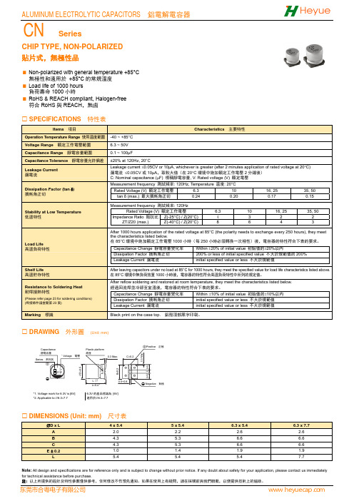
CHIP TYPE, NON-POLARIZED貼片式,無極性品Non-polarized with general temperature +85°C 無極性和適用於 +85°C 的常規溫度 Load life of 1000 hours 負荷壽命1000小時RoHS & REACH compliant, Halogen-free 符合RoHS 與REACH ,無鹵SPECIFICATIONS 特性表Items 項目Characteristics 主要特性Operation Temperature Range 使用温度範圍-40 ~ +85°C Voltage Range 額定工作電壓範圍 6.3 ~ 50V Capacitance Range 靜電容量範圍 0.1 ~ 100μFCapacitance Tolerance 靜電容量允許偏差 ±20% at 120Hz, 20°CLeakage Current 漏電流Leakage current ≤0.05CV or 10μA, whichever is greater (after 2 minutes application of rated voltage at 20°C) 漏電流 ≤0.05CV 或10μA ,取較大值(在20°C 環境中施加額定工作電壓2分鐘後) C: Nominal capacitance (μF) 標稱靜電容量, V: Rated voltage (V) 額定電壓Dissipation Factor (tan δ)損耗角正切Measurement frequency 測試頻率: 120Hz, Temperature 温度: 20°C Rated Voltage (V) 額定工作電壓 6.3 10 16, 25 35, 50 tan δ (max.) 最大損耗角正切 0.24 0.20 0.17 0.15 Stability at Low Temperature低溫特性Measurement frequency 測試頻率: 120HzRated Voltage (V) 額定工作電壓 6.3 10 16, 25 35, 50Impedance Ratio 阻抗比ZT/Z20 (max.) Z(-25°C) / Z(20°C)43 2 2 Z(-40°C) / Z(20°C)8 64 3 Load Life 高溫負荷特性After 1000 hours application of the rated voltage at 85°C (the polarity needs to exchange every 250 hours), they meetthe characteristics listed below.在85°C 環境中施加額定工作電壓1000小時(每250小時必須轉換一次極性)後,電容器的特性符合下表的要求。
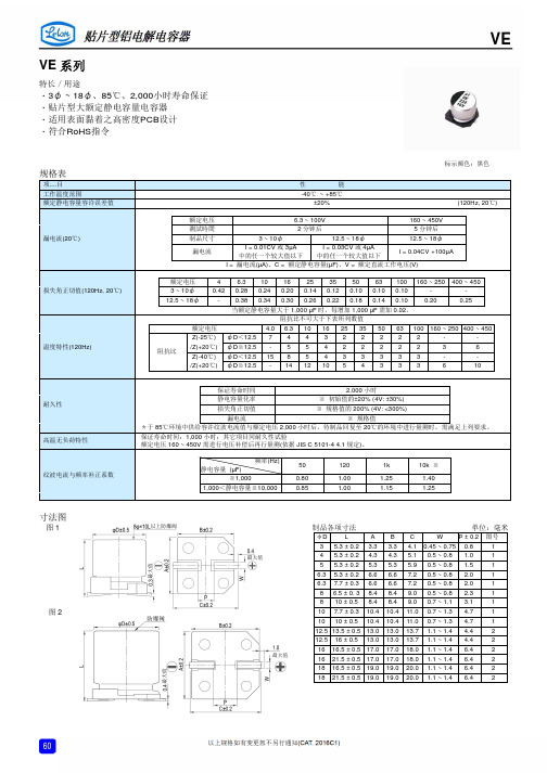
立隆---贴片型铝电 解电容规格书
-
-
12.5 ~ 18φ
- 0.38 0.34 0.30 0.26 0.22 0.18 0.14 0.10 0.20
0.25
当额定静电容量大于 1,000 µF 时,每增加 1,000 µF 需加 0.02。
阻抗比不可大于下表所列数值
额定电压
4.0 6.3 10 16 25 35 50 63 100 160 ~ 250 400 ~ 450
静电容量 (µF)
频率(Hz)
50
≦1,000
0.80
1,000<静电容量≦10,000
0.85
120
1.00 1.00
1k
10k ≦
1.25
1.40
1.15
1.25
寸法图
图1
图2
制品各项寸法
单位:毫米
φD
L
ABC
W P ± 0.2 图号
3 5.3 ± 0.2 3.3 3.3 4.1 0.45 ~ 0.75 0.8
18×16.5 16×21.5
18×21.5
1,450 1,500
1,750
16×16.5
18×16.5 16×21.5
18×21.5
1,100
1,450 1,500
1,750
18×16.5 16×21.5
1,350 1,400
10,000 103
18×21.5 2,000 18×21.5 2,000
124 175 270
6.3×7.7 8×10
124 270
8×10 10×7.7
270 270
8×10 10×10
270 370
10×10
320 12.5×13.5 500
贴片铝电解电容规格与尺寸
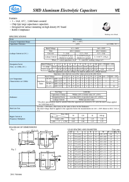
A 3.3 4.3 5.3 6.6 6.6 8.4 8.4 10.4 10.4 10.4 13.0 13.0 17.0 19.0
B 3.3 4.3 5.3 6.6 6.6 8.4 8.4 10.4 10.4 10.4 13.0 13.0 17.0 19.0
P ± 0.2 Fig. No. C W 4.1 0.45 ~ 0.75 0.8 1 5.1 0.5 ~ 0.8 1.0 1 6.1 0.5 ~ 0.8 1.5 1 7.4 0.5 ~ 0.8 2.0 1 7.4 0.5 ~ 0.8 2.0 1 9.2 0.7 ~ 1.1 3.1 1 9.2 0.7 ~ 1.1 3.1 1 11.2 0.7 ~ 1.1 4.7 1 11.2 0.7 ~ 1.1 4.7 1 11.2 0.7 ~ 1.1 4.7 1 15.0 1.1 ~ 1.4 4.4 2 15.0 1.1 ~ 1.4 4.4 2 19.0 1.1 ~ 1.4 6.4 2 21.0 1.1 ~ 1.4 6.4 2
φD×L mA
50V (1H)
φD×L 4×5.3 4×5.3 4×5.3 4×5.3 4×5.3 4×5.3 mA 3 5 6 7 10 14 17 20 35 50 65 75 75 190 190 190
63 (1J)
φD×L 4×5.3 4×5.3 4×5.3 4×5.3 4×5.3 4×5.3 5×5.3 5×5.3 6.3×5.3 8×10 8×10 10×10 10×10 10×10 mA 2 3 4 5 8 12 22 25 40 139 139 200 226 226
ห้องสมุดไป่ตู้
0R1 R22 R33 R47 010 2R2 3R3 4R7 100 220 330 470 680 101 151 221 331 471 681 102 222 332 472 682 V. DC 6.3×5.3 6.3×7.7 6.3×7.7 8×10 89 124 124 290 6.3×5.3 6.3×7.7 6.3×7.7 8×10 10×7.7 10×10 12.5×13.5 12.5×16 16×16.5 18×16.5 89 124 124 290 290 430 890 1,000 1,400 1,700 6.3×7.7 8×10 8×10 10×7.7 10×10 10×10 10×10 12.5×13.5 16×16.5 16×16.5 18×16.5 124 270 290 290 400 410 430 890 1,300 1,400 1,700 6.3×7.7 8×10 8×10 10×7.7 10×10 10×10 12.5×13.5 16×16.5 16×16.5 18×16.5 124 270 290 290 400 410 750 1,100 1,300 1,600 8×10 10×7.7 10×10 10×10 12.5×13.5 12.5×13.5 16×16.5 18×16.5 270 270 400 400 680 750 1100 1,450 3×5.3 4×5.3 4×5.3 5×5.3 5×5.3 6.3×5.3 16 31 34 58 58 89 3×5.3 4×5.3 4×5.3 4×5.3 5×5.3 5×5.3 6.3×5.3 6.3×5.3 16 26 31 34 55 58 89 89 3×5.3 4×5.3 5×5.3 4×5.3 5×5.3 6.3×5.3 5×5.3 6.3×5.3 6.3×5.3 6.3×7.7 14 26 44 31 55 75 58 89 89 109 3×5.3 4×5.3 4×5.3 5×5.3 5×5.3 5×5.3 6.3×5.3 6.3×5.3 6.3×5.3 6.3×7.7 14 26 30 44 55 55 75 89 89 109 3×5.3 4×5.3 5×5.3 5×5.3 6.3×5.3 5×5.3 6.3×5.3 6.3×5.3 6.3×7.7 6.3×7.7 6.3×7.7 14 26 44 47 59 55 67 75 98 109 109 3×5.3 4×5.3 5×5.3 5×5.3 6.3×5.3 6.3×5.3 6.3×7.7 6.3×7.7 6.3×7.7 8×10 10×7.7 8×10 10×10 10×10.3 12.5×13.5 12.5×13.5 16×16.5 18×16.5 14 26 44 47 59 67 85 98 109 252 252 270 370 400 750 680 1,100 1,450
贴片电解电容的规格

贴片电解电容的规格→贴片电解电容详细规格书选贴片电容就在东莞荣誉电子。
铝电解电容器的工作介质为通过阳极氧化的方式在铝箔表面生成一层极薄的三氧化二铝(Al2O3),此氧化物介质层和电容器的阳极结合成一个完整的体系,两者相互依存,不能彼此独立;我们通常所说的电容器,其电极和电介质是彼此独立的。
电解电容器的阳极铝箔、阴极铝箔通常均为腐蚀铝箔,实际的表面积远远大于其表观表面积,这也是铝质电解电容器通常具有大的电容量的一个原因。
由于采用具有众多微细蚀孔的铝箔,通常需用液态电解质才能更有效地利用其实际电极面积。
贴片电解电容技术:1 影响大型铝电解电容器耐纹波电流能力的因素通常情况下纹波电流Ir为Ir=(1)式中:α为散热系数;Δt为电容芯包温度与环境温度差(温升);A为电容外表面积。
从式(1)中可知,纹波电流Ir与和成正比。
散热系数α,它包括幅射散热和对流散热,它不仅与产品表面的温度差、直径大小、直立或横卧有关,而且与芯包结构、电容器内的导热情况、热流方向、芯包固定方式等密切相关。
由铝电解电容器等效电路可知tanδ=ωCR(2)式中:R为等效串联电阻,它由三部分所组成,即R=R1+R2+R3(3)式中:R1是氧化膜介质损耗所代表的等效串联电阻;R3是极板、导电层的欧姆电阻以及其间的接触电阻;R2是电解质所代表的等效串联电阻,即R2=φ·ρ·d/2s(4)式中:φ为电解纸的渗透系数;ρ为工作电解液的电阻率(Ω·cm);d为电解纸的厚度(cm);s为阳极箔的外观几何尺寸(cm2)。
由以上分析可知,选用氧化膜介质损耗小的铝箔,选择渗透系数小、厚度薄的电解纸,降低工作电解液的电阻率和粘度,改进产品结构等都可明显降低产品的tanδ。
通过降低tanδ,增大产品的散热系数,都可提高产品耐纹波电流的能力,从而保证产品达到寿命长等要求。
2 变频器对大型铝电解电容器的技术要求变频器的简单工作原理图如图1所示。
贴片铝电解电容低阻抗长寿命FZ系列规格书

CHIP TYPE, LONG LIFE WITH EXTRA LOWER IMPEDANCE貼片式,長壽命極低阻抗品Extra lower impedance with temperature range -55~+105°C 極低阻抗和適用於 -55~+105°C 的溫度範圍 Load life of 2000~5000 hours 負荷壽命2000~5000小時Impedance 5~25% less than KZ series 阻抗值比KZ 系列低5~25%RoHS & REACH compliant, Halogen-free 符合RoHS 與REACH ,無鹵SPECIFICATIONS 特性表Items 項目Characteristics 主要特性Operation Temperature Range 使用温度範圍-55 ~ +105°C Voltage Range 額定工作電壓範圍 6.3 ~ 100V Capacitance Range 靜電容量範圍 3.3 ~ 8200μF Capacitance Tolerance 靜電容量允許偏差±20% at 120Hz, 20°CLeakage Current 漏電流Leakage current ≤0.01CV or 3μA (∅4~∅10), whichever is greater (after 2 minutes application of rated voltage at 20°C)Leakage current ≤0.03CV or 4μA (∅12.5~∅18), whichever is greater (after 1 minute application of rated voltage at 20°C)漏電流 ≤0.01CV 或3μA (∅4~∅10),取較大值(在20°C 環境中施加額定工作電壓2分鐘後) 漏電流 ≤0.03CV 或4μA (∅12.5~∅18),取較大值(在20°C 環境中施加額定工作電壓1分鐘後) C: Nominal capacitance (μF) 標稱靜電容量, V: Rated voltage (V) 額定電壓Dissipation Factor (tan δ) 損耗角正切Measurement frequency 測試頻率: 120Hz, Temperature 温度: 20°C Rated Voltage (V) 額定工作電壓 6.3 10 16 25 35 50 63~80100tan δ (max.) 最大損耗角正切 ∅4~∅100.26 0.19 0.16 0.14 0.12 0.10 0.08 0.07 ∅12.5~∅180.26 0.19 0.18 0.16 0.14 0.10 0.08 0.07 Stability at Low Temperature 低溫特性Measurement frequency 測試頻率: 120HzRated Voltage (V) 額定工作電壓6.3 ~ 1625 ~ 100Impedance Ratio阻抗比 ZT/Z20 (max.) Z(-25°C) / Z(20°C) 2 2 Z(-40°C) / Z(20°C) 3 3 Z(-55°C) / Z(20°C)43Load Life 高溫負荷特性After 5000 hrs. (2000 hrs. for ∅4~∅6.3×5.8) application of the rated voltage at 105°C, they meet the characteristics listed below.在105°C 環境中施加額定工作電壓5000小時(∅4~∅6.3×5.8為2000小時)後,電容器的特性符合下表的要求。
贴片电解电容规格

After storage for 1000 hours at +105 °C±2 °C with no voltage applied and then being stabilized at +20 °C, capacitors shall meet the limits specified in Endurance. (With voltage treatment) After reflow soldering and then being stabilized at +20 °C, capacitor shall meet the following limits.
Endurance : 105 °C 1000 h
Min. Packaging Q'ty Reflow Taping (pcs) 2000 2000 2000 1000 1000 1000 1000 900 500 500 500 500 500 2000 2000 1000 1000 1000 1000 900 500 500 500 500 2000 2000 1000 1000 1000 1000 1000 900 500 500 500 500 500 500 500
S
■ Specifications
Category Temp. Range Rated W.V. Range Nominal Cap. Range Capacitance Tolerance DC Leakage Current tan δ W.V. (V) Characteristics at Low Temperature Z(–25 °C)/Z(+20 °C) Z(–40 °C)/Z(+20 °C) 6.3 4 8 10 3 6 –40 °C to +105 °C 6.3 V.DC to 100 V.DC 0.1 µF to 1500 µF ±20 % (120 Hz/+20 °C) I < 0.01 CV or 3 (µA) After 2 minutes (Whichever is greater) Please see the attached standard products list 16 2 4 25 2 4 35 2 3 50 2 3 63 3 4 100 3 4 (Impedance ratio at 120 Hz)
贴片铝电解电容长寿命KL系列规格书
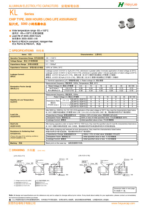
CHIP TYPE, 5000 HOURS LONG LIFE ASSURANCE 貼片式,5000小時長壽命品Wide temperature range -55~+105°C 適用於 -55~+105°C 的寬溫範圍 Load life of 3000~5000 hours 負荷壽命3000~5000小時RoHS & REACH compliant, Halogen-free 符合RoHS 與REACH ,無鹵SPECIFICATIONS 特性表Items 項目Characteristics 主要特性Operation Temperature Range 使用温度範圍-55 ~ +105°C Voltage Range 額定工作電壓範圍 6.3 ~ 100V Capacitance Range 靜電容量範圍 0.1 ~ 1500μF Capacitance Tolerance 靜電容量允許偏差±20% at 120Hz, 20°CLeakage Current漏電流Leakage current ≤0.01CV or 3μA (∅4~∅10), whichever is greater (after 2 minutes application of rated voltage at 20°C)Leakage current ≤0.03CV or 4μA (∅12.5~∅16), whichever is greater (after 1 minute application of rated voltage at 20°C)漏電流 ≤0.01CV 或3μA (∅4~∅10),取較大值(在20°C 環境中施加額定工作電壓2分鐘後) 漏電流 ≤0.03CV 或4μA (∅12.5~∅16),取較大值(在20°C 環境中施加額定工作電壓1分鐘後) C: Nominal capacitance (μF) 標稱靜電容量, V: Rated voltage (V) 額定電壓Dissipation Factor (tan δ) 損耗角正切Measurement frequency 測試頻率: 120Hz, Temperature 温度: 20°CRated Voltage (V) 額定工作電壓 6.3 10 16 25 35 50~100tan δ (max.) 最大損耗角正切 ∅4~∅100.28 0.24 0.20 0.16 0.13 0.12 ∅12.5~∅16 0.38 0.34 0.30 0.26 0.22 0.18 Stability at Low Temperature 低溫特性Measurement frequency 測試頻率: 120HzRated Voltage (V) 額定工作電壓6.3 10 16 25 35 50~100Impedance Ratio 阻抗比ZT/Z20 (max.) ∅4~∅10Z(-25°C) / Z(20°C)3 3 2 2 2 2 Z(-55°C) / Z(20°C)8 5 4 3 3 3 ∅12.5~∅16Z(-25°C) / Z(20°C)5 4 3 2 2 2 Z(-55°C) / Z(20°C)12 10 8 5 4 3Load Life 高溫負荷特性After 5000 hrs. (3000 hrs. for ∅4~∅6.3×5.8) application of the rated voltage at 105°C, they meet the characteristics listed below.在105°C 環境中施加額定工作電壓5000小時(∅4~∅6.3×5.8為3000小時)後,電容器的特性符合下表的要求。
贴片铝电解电容规格
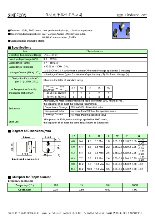
■ Multiplier for Ripple Current Frequency coefficient Frequency (Hz) Coefficient
120 0.70 1K 0.80 10K 0.90 100K 1.00
信达电子零件有限公司 www.sindecon.com 技术支持:rain@sindecon.com在线服务QQ:730381936
0.65±0.1 1.0±0.2 0.35 0.65±0.1 1.5±0.2 0.35 0.65±0.1 1.8±0.2 0.35 0.65±0.1 1.8±0.2 0.35
10.0 Max 3.4 12.0 Max 3.5
0.90±0.2 3.1±0.2 0.70 ±0.2 0.90±0.2 4.6±0.2 0.70 ±0.2
Shelf Life
After placed at 105℃without voltage applied for 1000 hours, the capacitor shall meet the same requirement as Endurance.
■ Diagram of Dimension零件有限公司 www.sindecon.com
■Case Size / tanδ/ Max Ripple Current / Impedance
Rated (Surge) Voltage Capacitance (μF) ψDxL 22 33 47 100 150 220 330 470 680 1000 1500 4x5.4 4x5.4 4x5.4 5x5.4 5x5.4 6.3x5.4 6.3x7.7 6.3x7.7 6.3x7.7 8x10.2 8x10.2 8x10.2 10x10.2 6.3(8) tanδ 0.26 0.26 0.26 0.26 0.26 0.26 0.26 0.26 0.26 0.26 0.26 0.26 0.26 RC 90 90 90 160 160 240 240 240 280 600 600 600 850 Z 1.93 1.93 1.93 1.00 1.00 0.52 0.30 0.30 0.34 0.16 0.16 0.16 0.08 ψDxL 4x5.4 4x5.4 5x5.4 6.3x5.4 6.3x5.4 6.3x7.7 6.3x7.7 8x10.2 8x10.2 10x10.2 10x10.2 10(13) tanδ 0.19 0.19 0.19 0.19 0.19 0.19 0.19 0.19 0.19 0.19 0.19 RC 90 90 160 190 190 240 280 600 600 600 850 Z 1.93 1.93 1.00 0.52 0.52 0.34 0.34 0.16 0.16 0.12 0.08 ψDxL 4x5.4 5x5.4 5x5.4 5x5.4 6.3x5.4 6.3x5.4 6.3x7.7 6.3x7.7 8x10.2 8x10.2 8x10.2 10x10.2 16(20) tanδ 0.16 0.16 0.16 0.16 0.16 0.16 0.16 0.16 0.16 0.16 0.16 0.16 RC 90 160 160 160 240 240 280 280 370 600 600 850 Z 1.93 1.00 1.00 1.00 0.52 0.52 0.34 0.34 0.22 0.16 0.16 0.08
贴片铝电解电容规格书丝印说明
贴片铝电解电容规格书丝印说明引言:贴片铝电解电容是一种常见的电子元件,广泛应用于电子设备中。
规格书丝印说明是指印在电容器表面的一些标识和文字,用于表示电容器的参数和特性。
本文将详细介绍贴片铝电解电容规格书丝印说明的含义和解读方法。
一、电容值在贴片铝电解电容规格书丝印说明中,电容值通常以uF为单位表示,例如"100uF"表示电容器的电容值为100微法。
该数值表示了电容器可以储存的电荷量,越大的电容值意味着电容器可以储存更多的电荷。
根据实际需求,可以选择合适的电容值来满足电路的要求。
二、电压值电容器的电压值也是规格书丝印说明中的重要参数之一,通常以V 或者VDC为单位表示,例如"16V"表示电容器的额定工作电压为16伏特。
电压值是指电容器可以承受的最大工作电压,超过该电压可能导致电容器损坏。
在选择电容器时,应根据电路的电压要求选择合适的电压值,以确保电容器的安全工作。
三、温度系数贴片铝电解电容规格书丝印说明中还包含了温度系数的标识,通常以字母表示,例如"E"表示温度系数为-55℃~+105℃。
温度系数是指电容值随温度变化的程度,不同的温度系数对应不同的应用环境。
在高温环境下,应选择具有较高温度系数的电容器,以保证电容值的稳定性。
四、极性贴片铝电解电容是一种极性元件,规格书丝印说明中通常会标明正负极性,例如"+"和"-"符号。
正极性表示电容器的正极,负极性表示电容器的负极,接线时应确保正确连接,否则可能导致电容器损坏。
五、尺寸和外观贴片铝电解电容的规格书丝印说明中还包含了尺寸和外观的标识,通常以数字和字母组合表示,例如"6.3×5.4"表示电容器的尺寸为6.3毫米×5.4毫米。
尺寸和外观标识有助于确定电容器的安装位置和布局,以便于电路设计和组装。
结论:贴片铝电解电容规格书丝印说明提供了关于电容器参数和特性的重要信息,正确解读规格书丝印说明对于选择和使用电容器至关重要。
贴片铝电解电容高压长寿命CP系列规格书
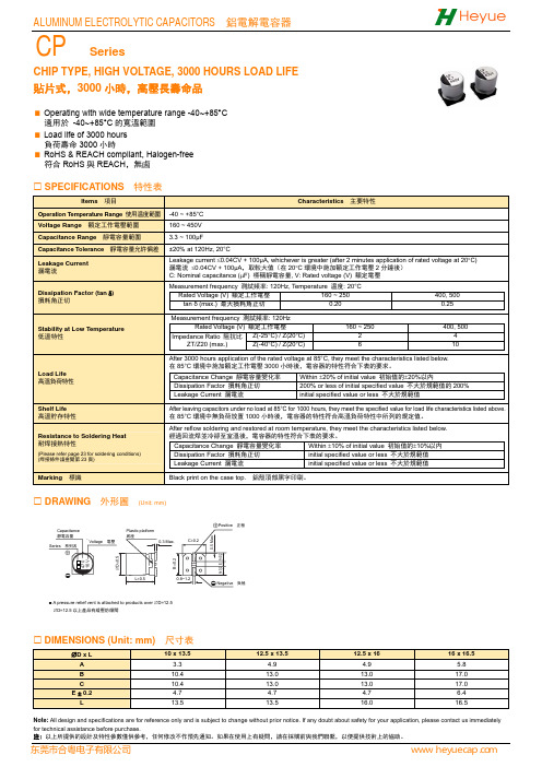
CHIP TYPE, HIGH VOLTAGE, 3000 HOURS LOAD LIFE貼片式,3000小時,高壓長壽命品Operating with wide temperature range -40~+85°C適用於 -40~+85°C的寬溫範圍Load life of 3000 hours負荷壽命3000小時RoHS & REACH compliant, Halogen-free符合RoHS與REACH,無鹵SPECIFICATIONS 特性表Items 項目Characteristics 主要特性Operation Temperature Range 使用温度範圍-40 ~ +85°CVoltage Range 額定工作電壓範圍160 ~ 450VCapacitance Range 靜電容量範圍 3.3 ~ 100μFCapacitance Tolerance 靜電容量允許偏差±20% at 120Hz, 20°CLeakage Current 漏電流Leakage current ≤0.04CV + 100μA, whichever is greater (after 2 minutes application of rated voltage at 20°C) 漏電流 ≤0.04CV + 100μA,取較大值(在20°C環境中施加額定工作電壓2分鐘後)C: Nominal capacitance (μF) 標稱靜電容量, V: Rated voltage (V) 額定電壓Dissipation Factor (tan δ) 損耗角正切Measurement frequency 測試頻率: 120Hz, Temperature 温度: 20°CRated Voltage (V) 額定工作電壓160 ~ 250 400, 500tan δ (max.) 最大損耗角正切 0.20 0.25Stability at Low Temperature 低溫特性Measurement frequency 測試頻率: 120HzRated Voltage (V) 額定工作電壓160 ~ 250400, 500Impedance Ratio 阻抗比ZT/Z20 (max.)Z(-25°C) / Z(20°C) 2 4Z(-40°C) / Z(20°C) 6 10Load Life高溫負荷特性After 3000 hours application of the rated voltage at 85°C, they meet the characteristics listed below.在85°C環境中施加額定工作電壓3000小時後,電容器的特性符合下表的要求。
贴片铝电解电容规格书丝印说明
贴片铝电解电容规格书丝印说明贴片铝电解电容规格书丝印说明尊敬的用户,非常感谢您选择使用我们的贴片铝电解电容。
为了确保您正确使用并发挥出电容的最佳性能,我们特意为您准备了这篇规格书丝印说明。
请您详细阅读以下内容,并在使用过程中遵循相关指导。
1. 规格说明:- 容量(C):我们的电容提供了多种容量选择,从微型电容到大容量电容,以满足不同应用的需求。
请在选型时仔细考虑您的具体应用场景,确保所选容量符合要求。
- 电压(V):我们提供了不同电压等级的电容。
在使用过程中,请务必确保所选电压等级高于或等于所需工作电压,防止超压损坏电容。
- 允许偏差:由于制造工艺和环境因素的影响,电容的容量和电压可能会存在一定的偏差。
这些偏差通常在规格书丝印上做了标注,请您在使用前了解并合理考虑。
2. 丝印标识:- 容量标识:容量通常以“μF”为单位进行标识,并在丝印上以数字形式显示。
例如,若丝印显示为100,则表示容量为100微法(μF)。
- 电压标识:电容的电压等级通常以“V”为单位进行标识,并在丝印上以数字形式显示。
例如,若丝印上显示为25V,则表示电容的电压等级为25伏特(V)。
- 极性标识:贴片铝电解电容通常为极性电容,正极和负极在表面上会有相应的标记。
请您在使用过程中务必将电容的正极正确连接至正极引脚,负极正确连接至负极引脚。
若连接错误,可能会导致电容损坏或运行异常。
3. 使用注意事项:- 工作温度范围:请确保您的贴片铝电解电容在指定的工作温度范围内使用,避免过高或过低温度对电容造成不可逆的损坏。
- 频率特性:贴片铝电解电容的频率特性可能会受到影响。
在设计电路时,请仔细考虑频率范围,以确保电容在所需频率下表现出稳定的性能。
- 存储条件:若您暂时不使用电容,请将其存放在低温、低湿的环境中,避免长期暴露在高温、高湿的环境下,以防电容受潮和损坏。
总之,通过仔细阅读本规格书丝印说明,并遵循所述的指导,您将能够正确选择和使用我们的贴片铝电解电容。
电解电容规格书(带封面)
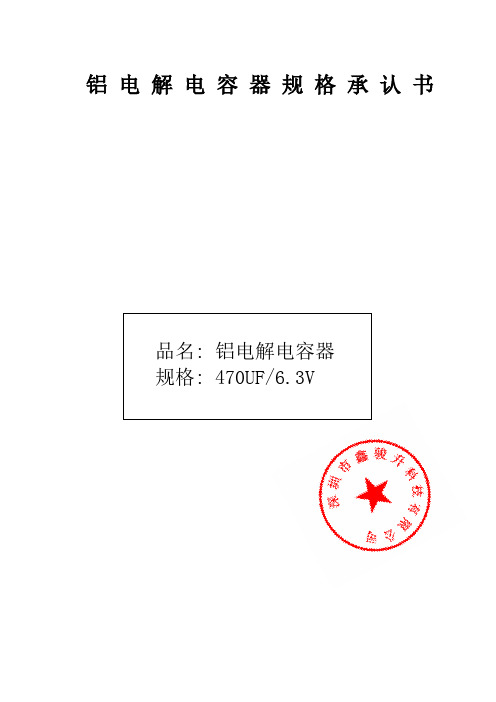
铝电解电容器规格承认书品名: 铝电解电容器规格: 470UF/6.3V5ALUMINUM ELECTROLYTIC CAPACITORS SPECIFICATION FOR APPOV AL铝电解电容器规格承认书表1:承认项目Type DimensionsTABLE1 RATING&CHARACTERISTIC.CHONG 产品系列表CHONG■NOTE:以上所提供的设计及特性参数谨供参考作用,任何修改不作预先通知.如果在使用上有疑问,请在采购前与我们联络, 以便提供技术上的协助!LEAD FREE TYPE REFLOW SOLDERING CONDITION无 铅 焊 料 产 品 的 回 流 焊 条 件● Recommended Conditions for Reflow Soldering 无铅焊料产品遵循的回流焊条件 (1) Preheat shall be made at 100℃~200℃ and for maximum 180 seconds. 100℃~200℃的预热时间不得超过180秒钟。
(2) Period that temperature at top of capacitor becomes more than 200℃and 230℃shall notexceed t and t1 seconds, respectively.电容器顶部温度高于200℃和230℃的时间,分别不得超过t 和t1所限定的时间。
(3) Temperature at top of capacitor shall not exceed T(℃).在回流焊接时,电容器顶部的最高温度不得超过T (℃)所限定的温度。
● Temperature/Time profile 回流焊温度与时间曲线图● Allowable Range of Peak Temperature 不同壳号的焊接温度及时间● Recommended Land Size 各种壳号的安装尺寸(m m)ALUMINUM ELECTROLYTIC CAPACITORS 'LIFE关于铝电解电容器的寿命T e m p e r a t u r e a t C a p a c i t o r s t o p (℃)Peak temperatureTime (second)Preheat 180sec Maxt sec Maxt1 sec MaxThe life of non-solid aluminum electrolytic capacitors is mainly dependent on environmental conditions (e.g. ambient temperature, humidity etc.) and electrical factors(e.g. operating voltage, ripple current etc.).Generally, the wear-out mechanism of non-solid aluminum electrolytic capacitors is based on evaporation of electrolyte through the rubber seal. Consequently, the factor of temperature (ambient temperature and internal heating due to ripple current) is the most critical to electrolytic capacitor life. The effect of voltage on capacitor life is negligible, especially for low voltage electrolytic capacitors. The lifetime of non-solid aluminum electrolytic capacitors can be expressed as following equations:非固体铝电解电容器的寿命主要依赖于使用环境条件(如环境温度,湿度等)和电负荷情况(如工作电压,纹波电流等)。
铝电解电容器规格承认书
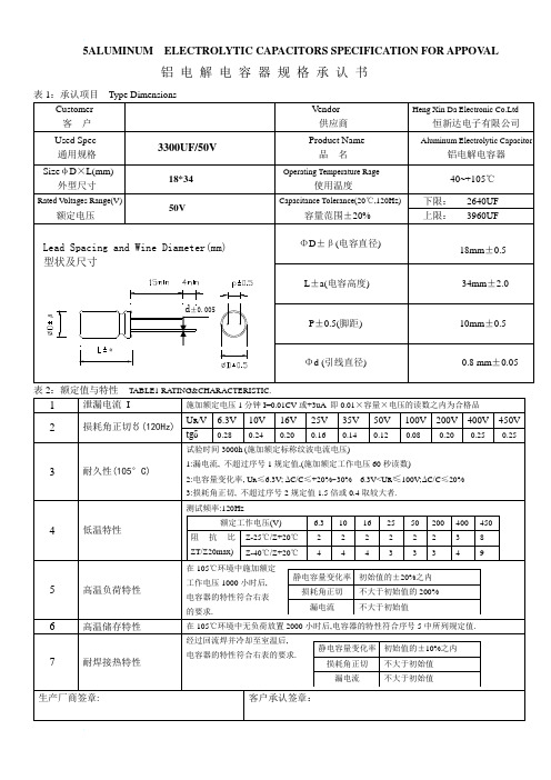
5ALUMINUM ELECTROLYTIC CAPACITORS SPECIFICATION FOR APPOV AL 铝电解电容器规格承认书TABLE1 RATING&CHARACTERISTIC.CONTENTS 产品系列表SERIESNOTE:以上所提供的设计及特性参数谨供参考作用,任何修改不作预先通知.如果在使用上有疑问,请在采购前与我们联络,以便提供技术上的协助!LEAD FREE TYPE REFLOW SOLDERING CONDITION无 铅 焊 料 产 品 的 回 流 焊 条 件● Recommended Conditions for Reflow Soldering 无铅焊料产品遵循的回流焊条件 (1) Preheat shall be made at 100℃~200℃ and for maximum 180 seconds. 100℃~200℃的预热时间不得超过180秒钟。
(2) Period that temperature at top of capacitor becomes more than 200℃and 230℃shall notexceed t and t1 seconds, respectively.电容器顶部温度高于200℃和230℃的时间,分别不得超过t 和t1所限定的时间。
(3) Temperature at top of capacitor shall not exceed T(℃).在回流焊接时,电容器顶部的最高温度不得超过T (℃)所限定的温度。
● Temperature/Time profile 回流焊温度与时间曲线图● Allowable Range of Peak Temperature 不同壳号的焊接温度及时间Size T(℃) t(second) t1(second)φ4~φ6.3 250 90 40 φ8×10.5L 240 90 30 φ10×10.5L2356030● Recommended Land Size 各种壳号的安装尺寸(m m)Size X Y a φ4 1.6 2.6 1.0 φ5 1.6 3.0 1.4 φ6.3 1.6 3.5 2.1 φ8×10.5L 2.5 3.5 3.0 φ10×10.5L2.54.04.0T e m p e r a t u r e a t C a p a c i t o r s t o p (℃)Peak temperatureTime (second)Preheat 180sec Maxt sec Maxt1 sec MaxALUMINUM ELECTROLYTIC CAPACITORS'LIFE关于铝电解电容器的寿命The life of non-solid aluminum electrolytic capacitors is mainly dependent on environmental conditions (e.g. ambient temperature, humidity etc.) and electrical factors(e.g. operating voltage, ripple current etc.).Generally, the wear-out mechanism of non-solid aluminum electrolytic capacitors is based on evaporation of electrolyte through the rubber seal. Consequently, the factor of temperature (ambient temperature and internal heating due to ripple current) is the most critical to electrolytic capacitor life. The effect of voltage on capacitor life is negligible, especially for low voltage electrolytic capacitors. The lifetime of non-solid aluminum electrolytic capacitors can be expressed as following equations:非固体铝电解电容器的寿命主要依赖于使用环境条件(如环境温度,湿度等)和电负荷情况(如工作电压,纹波电流等)。
贴片铝电解电容宽温长寿命EL系列规格书

DRAWING 外形圖 (Unit: mm)
10 16V ∅D±0.5 B±0.2
0.5 Max. A±0.2 E A±0.2
470 16V ∅D±0.5 B±0.2
0.5 Max. A±0.2 E A±0.2
(∅4~∅6.3×7.7)
Capacitance 靜電容量
Series 系列名
⊕
*1 Voltage 電壓
35
22
220 4 × 5.8
22
5 × 5.8
25
5 × 5.8
27
6.3 × 5.8
36
6.3 × 5.8
38
6.3 × 7.7
70
33
330 5 × 5.8
27
5 × 5.8
30
6.3 × 5.8
40
6.3 × 5.8
60
6.3 × 7.7
84
8 × 10.5
90
47
470 5 × 5.8
33
C: Nominal capacitance (μF) 標稱靜電容量, V: Rated voltage (V) 額定電壓
Measurement frequency 測試頻率: 120Hz, Temperature 温度: 20°C
Rated Voltage (V) 額定工作電壓
6.3
10
16
25
35
105
6.3 × 7.7
95
8 × 10.5
140
10 × 10.5 315 10 × 10.5 100
100
8 × 10.5
210
8 × 10.5
210
10 × 10.5
- 1、下载文档前请自行甄别文档内容的完整性,平台不提供额外的编辑、内容补充、找答案等附加服务。
- 2、"仅部分预览"的文档,不可在线预览部分如存在完整性等问题,可反馈申请退款(可完整预览的文档不适用该条件!)。
- 3、如文档侵犯您的权益,请联系客服反馈,我们会尽快为您处理(人工客服工作时间:9:00-18:30)。
温度范围从-55℃至+105℃
Lead-free reflow soldering is available subject to customer’s request
宽温长寿命品
Wide temperature range -55℃ to +105℃ with load life of 3000 hours
Capacitance Change 静电容量变化率 Tan 损耗角正切
Within ±10% of the initial value 初始值±10%以内 Initial specified value or less不大于规范值
Leakage Current 漏电流 Initial specified value or less不大于规范值WV 电压6.3 源自J10 1A16 1C
25 1E
35 1E
4×5.8 4×5.8 4×5.8 4×5.8 4×5.8 4×5.8 4×5.8
50 1E
1 2 3 5 10 16 16 23 35 70 (70) 90 90 100 100 250 (100) 400 650 (500)
0R1
R22 R33 R47 101 2R2 3R3 4R7 100 220 330 470 101 151 221 331 471 681 102 152 222 332 472
4×5.8 5×5.8 5×5.8 6.3×5.8 6.3×5.8 6.3×7.7 8×10.5 8×10.5 8×10.5 10×10.5 10×13.5 (10×10.5) 12.5×13.5 12.5×16 16×21.5 22 27 33 50 55 100 210 210 210 315 450 (315) 620 750 1250 5×5.8 5×5.8 6.3×5.8 6.3×5.8 (8×6.2) 6.3×7.7 8×10.5 8×10.5 10×10.5 10×10.5 10×13.5 (10×10.5) 12.5×13.5 12.5×16 (12.5×13.5) 16×16.5 16×21.5 25 30 41 53 (110) 105 210 210 315 315 360 (315) 500 650 (600) 950 1250 4×5.8 5×5.8 6.3×5.8 6.3×5.8 6.3×5.8 6.3×7.7 8×10.5 8×10.5 10×10.5 10×10.5 12.5×13.5 (10×13.5) (10×10.5) 12.5×13.5 16×16.5 16×21.5 16×21.5 18 27 40 48 60 95 210 210 315 315 450 (350) (315) 550 900 1150 1300 4×5.8 5×5.8 6.3×5.8 6.3×7.7 (8×6.2) 8×10.5 8×10.5 10×10.5 10×10.5 10×10.5 10×10.5 10×13.5 12.5×13.5 12.5×16 16×16.5 16×21.5 16×21.5 13 20 36 60 90 (91) 130 140 190 315 315 380 550 800 1000 1200 1350 16×21.5 1250 4×5.8 5×5.8 6.3×5.8 6.3×7.7 (8×6.2) 8×10.5 8×10.5 10×10.5 10×10.5 10×10.5 12.5×13.5 (10×13.5) 12.5×13.5 16×16.5 (12.5×16) 14 21 38 84 (84) 98 130 315 315 315 500 (360) 500 700 (550)
规格尺寸及最大允许纹波电流及ESR值 Standard size Maximum permissible ripple current&ESR
容量 Cap(uF)
0.1 0.22 0.33 0.47 1 2.2 3.3 4.7 10 22 33 47 100 150 220 330 470 680 1000 1500 2200 3300 4700
After leaving capacitors under no load at 105℃ for 1000 hours, they meet the specified value for load life characteristics listed above. 在105℃环境中无负荷放置1000小时后,电容器的特性符合高温负荷特性中所列的规定值。
适用标准 Applicable Standards
IEC-60384-18
*1 Voltage mark [6V] represents 6.3V for Ф4~Ф10; *2 [L±0.5] is applicable to Φ8×10.5~Ф10; *3 [L±1.0] is applicable to Φ12.5~Ф16.Re: Date code and series type —1st digit for Year; 2nd digit for Quarter, 4 quarter codes in one year are 1, 4, 7, O; 3rd character for Series; EL Series = E.
EL
DXL A B C E±0.2 L Φ4X5.8 1.8 4.3 4.3 1.0 5.8 Φ5X8 2.1 5.3 5.3 1.3 5.8 Φ6.3X5.8 / 7.7 2.4 6.6 6.6 2.2 5.8 / 7.7 Φ8X6.2 3.3 8.3 8.3 2.2 6.2 Φ8X10.5 Φ10X10.5 / 13.5 2.9 8.3 8.3 3.1 10.5 3.2 10.3 10.3 4.4 10.5 / 13.5 Φ12.5X13.5 / 16 4.7 13.0 13.0 4.4 13.5 / 16 Φ16X16.5 / 21.5 5.5 17.0 17.0 6.7 16.5 / 21.5
无铅回流焊接可按照客户的要求
项目 Item
-55 ~ +105℃
特性 Performance Characteristics
6.3
静电容量范围 Capacitance Range 静电容量允许偏差Capacitance Tolerance
50
0.1~4700 μF ±20% at 120 Hz, 20 For Φ4~Φ10,after 2 minutes’s application of rated voltage,leakagecurrent is not more than 0.01CV or 3(μΑ),whichever is greater.For Φ12.5~Φ16,after 1 minutes application of rated voltage,leakage current is not more than 0.03CV or 4(μΑ), whichever is greater. Φ4~Φ10; 施加额定工作电压2分钟,LC≤0.01CV或3(μΑ),取较大值; Φ12.5~Φ16; 施加额定工作电压1分钟,LC≤0.03CV或4(μΑ),取较大值。 Measurement frequency
10 3 5 4 10
16 2 4 3 8
25 2 3 2 5
35 2 3 2 4
50 2 3 2 3
Φ4~Φ10 Φ12.5~Φ16
Z(-25℃)/Z(20℃) Z(-55℃)/Z(20℃) Z(-25℃)/Z(20℃) Z(-55℃)/Z(20℃)
高温负荷特性 Load Life
Capacitance Change Within ±25% of the initial value After 3000 hours (2000 hours for Φ4~Φ6.3 and 静电容量变化率 初始值±25%以内 Φ8×6.2) application of rated voltage at 105℃, 200% or less of the initial specified value capacitions meet the characteristics requirements Tan 损耗角正切 初始值的±200%以内 listed at right. 在105℃环境中施加额定工作电压3000小时(Φ4~Φ Leakage Current 漏电流 Initial specified value or less不大于规范值 6.3和 Φ8×6.2为2000小时后,电容器的特性符合 右表的要求。
Φ4~Φ10 Φ12.5~Φ16
Measurement frequency 测试频率: 120Hz
低温特性 Stability at Low Temperature
Rated voltage(V.DC) 额定工作电压 Impedance ratio 阻抗比 XT/Z20(max)
6.3 3 8 5 12
300Hz
1.17 1.08 1.35 1.23
1kHz
1.36 1.20 1.57 1.34
10kHz~
1.50 1.30 2.00 1.50
Φ12.5~Φ16
100~470 680~4700
EL
Parts List (1)
Tangent of Loss Angle
(tan )
Size D ×
4×5.8 5×5.8 5×5.8 6.3×5.8 6.3×5.8 6.3×7.7 8×10.5 8×10.5 8×10.5 10×10.5 10×10.5 10×10.5 12.5×13.5 12.5×16 16×21.5 5×5.8 5×5.8 6.3×5.8 6.3×5.8 8×6.2 6.3×7.7 8×10.5 8×10.5 10×10.5 10×10.5 10×10.5 10×13.5 12.5×13.5 12.5×13.5 12.5×16 16×16.5 16×21.5 4×5.8 5×5.8 6.3×5.8 6.3×5.8 6.3×5.8 6.3×7.7 8×10.5 8×10.5 10×10.5 10×10.5 10×10.5 10×13.5
