SSDT_color_20070205
ssd1306双色中文
Ver:A
修正完成 20130326 20130522
i
金晨电子
Ver:A
内容
修正历史................................................................................................................................i 内容..................................................................................................................................... ii~iii 11.. 基本功能...............................................................................................................1~6
金晨电子
刘玉汉化,本人不会英文,以下翻译主要有谷歌翻译提供
金晨电子
产品名称: 产品ID:
OEL 显示模块
顾客:
批准
来自: 金晨电子
批准
金晨电子
修正历史
零件号码 UG-2864TMBEG01
修正 A B
内容
New
R 变更为 R IRE)参数 0XCF 变更为 0X66
1.1 显示规格 ................................................................................................................. 1 1.2 机械规格............................................................................................................ 1 1.3 有效面积 / 内存映射 & 像素结构...................................................................... 1 1.4 机械图纸.................................................................................................................... 2 1.5 引脚定义 ............................................................................................................................. 3 1.6 方框图............................................................................................................................ 5
M150XN07_07中文资料
M150XN07 V.2Product SpecificationAU OPTRONICS CORPORATIONProduct Specification15.0” XGA Color TFT-LCD ModuleModel Name: M150XN07 V.2Approved by Prepared byCC Chiu TC TsaiDDBU Marketing Division / AU Optronics corporationCustomer Checked & Approved byProduct Specification15.0” XGA Color TFT-LCD ModuleModel Name: M150XN07V.2 (u) Preliminary Specifications( ) Final Specifications Note: This Specification is subject to change without notice.Contents1.0 Handling Precautions (5)2.0 General Description (6)2.1 Display Characteristics (6)2.2 Optical Characteristics (7)3.0 Functional Block Diagram (12)4.0 Absolute Maximum Ratings (13)4.1 TFT LCD Module (13)4.2 Backlight Unit (13)4.3 Absolute Ratings of Environment (13)5.0 Electrical characteristics (14)5.1 TFT LCD Module (14)5.1.1 Power Specification (14)5.1.2 Signal Electrical Characteristics (15)5.2 Backlight Unit (16)6.0 Signal Characteristic (17)6.1 Pixel Format Image (17)6.2 The input data format (18)6.3 Signal Description (19)6.4 Interface Timing (20)6.4.1 Timing Characteristics (20)6.4.2 Timing diagram (21)6.5 Power ON/OFF Sequence (22)7.0 Connector & Pin Assignment (23)7.1 TFT LCD Module (23)7.2 Backlight Unit (24)7.3 Signal for Lamp connector (24)8.0 Reliability (25)9.0 Safety (26)9.1 Sharp Edge Requirements (26)9.2 Materials (26)9.2.1 Toxicity (26)9.2.2 Flammability (26)9.3 Capacitors (26)10.0 Other requirement (26)10.1 National Test Lab Requirement (26)10.2 Label (26)11.0 Mechanical Characteristics (27)Record of RevisionVersion and Date Page Old description New Description Remark 0.1 2005/02/14 All First Edition for Customer1.0 Handling Precautions1) Since front polarizer is easily damaged, pay attention not to scratch it.2) Be sure to turn off power supply when inserting or disconnecting from input connector.3) Wipe off water drop immediately. Long contact with water may cause discoloration or spots.4) When the panel surface is soiled, wipe it with absorbent cotton or other soft cloth.5) Since the panel is made of glass, it may break or crack if dropped or bumped on hard surface.6) Since CMOS LSI is used in this module, take care of static electricity and insure human earth whenhandling.7) Do not open nor modify the Module Assembly.8) Do not press or pat the panel surface by fingers,hand or tooling.9) Do not press the reflector sheet at the back of the module to any directions.10) In case if a module has to be put back into the packing container slot after once it was taken out from thecontainer, do not press the center of the CCFL reflector edge. Instead, press at the far ends of the CCFL reflector edge softly. Otherwise the TFT module may be damaged.11) At the insertion or removal of the Signal Interface Connector, be sure not to rotate nor tilt the InterfaceConnector of the TFT module.12) After installation of the TFT module into an enclosure (Desktop monitor Bezel, for example), do not twistnor bend the TFT Module even momentary. At designing the enclosure, it should be taken into consideration that no bending/twisting forces are applied to the TFT module from outside. Otherwise the TFT module may be damaged.2.0 General DescriptionThis specification applies to the 15.0 inch Color TFT/LCD Module M150XN07 V2.This module is designed for a display unit of personal computer.The display supports the XGA (1024 (H) x 768(V)) screen format and 16.2M colors (RGB 6-bits + FRC data). All input signals are 1 Channel LVDS interface compatible.This module does not contain an inverter card for backlight.2.1 Display CharacteristicsThe following items are characteristics summary on the table under 25 ℃condition:ITEMS Unit SPECIFICATIONSScreen Diagonal [mm] 381 (15”)Active Area [mm] 304.128 (H) x 228.096Pixels H x V 1024(x3) x 768Pixel Pitch [mm] 0.297 (per one triad) x 0.297Pixel Arrangement R.G.B. Vertical StripeDisplay Mode TN mode, Normally WhiteWhite Luminance [cd/m2] 250 (Typ) @ 8mAContrast Ratio 500 : 1 (Typ)Optical Rise Time/Fall Time [msec] 12 (Typ) (Note 1) Color Saturation 65% NTSCNominal Input Voltage VDD [Volt] +3.3 VPower Consumption(VDD line + CCFL line)[Watt] 13.3 W (Typ.) @8mA (All Black Pattern)Weight [Grams] 1100 (Typ)Min. Typ. Max.Horizatal(H) 326.0 326.5 327.0Vertical(V) 253.0 253.5 254.0Physical Size [mm]Depth(D) - - 12.0Electrical Interface 1 Channel LVDSSupport Color 16.2M colors (RGB 6-bit + FRC data)Temperature RangeOperating Storage (Shipping) [o C][o C]0 to +50-20 to +60Surface Treatment Hard-coating (3H), anti-glare treatment Note 1 :System should warm up for at least one hourmeasuring distance2.2 Optical CharacteristicsThe optical characteristics are measured under stable conditions at 25℃ (Room Temperature):Item Unit Conditions Min. Typ. Max.Note Horizontal (Right) CR = 10 (Left) TBD6565- Vertical (Up) CR = 10 (Down) TBD65 55keep total 120(Mayb e 60,60)Horizontal (Right) CR = 5 (Left) TBD TBD Viewing Angle [degree]Vertical (Up) CR = 5 (Down)TBD TBD Contrast ratioNormal Direction TBD 500 -Rising Time - TBD TBD Falling Time - TBD TBD Response Time[msec]Rising + Falling - 12 Note 1Red x 0.61 0.64 0.67 Red y0.30 0.33 0.36 Green x 0.27 0.30 0.33 Green y 0.56 0.59 0.62 Blue x 0.12 0.15 0.18 Color / Chromaticity Coordinates (CIE)Blue y0.07 0.10 0.13 White x 0.28 0.31 0.34 Color Coordinates(CIE)WhiteWhite y 0.30 0.33 0.36 White Luminance @ CCFL 8mA (center)[cd/m 2] 200 250 - Luminance Uniformity [%] 75 80 Note 2 Crosstalk (in 75Hz) [%] 1.2 1.5 Note 3 FlickerdB-20Note 4 Equipment Pattern Generator, Power Supply, Digital Voltmeter, Luminance meter (PR 880, BM-5A ,BM 7 ,CS-1000, CA210, SR_3 & EZ Contrast(ELDIM)* )Aperture1∘with 50cm viewing distanceTest Point Center (VESA point 9) Environment < 1 lux*’ EZ Contrast is different measurement tool with very close viewing distance.Note 1: Definition of Response timeThe output signals of photo detector are measured when the input signals are changed from “Black” to “White”(rising time), and from “White” to “Black ”(falling time), respectively. The response time is interval between the 10% and 90% of amplitudes.Note 2: Brightness uniformity of these 9 points is defined as below50 %90 % 90 % 50 %10 %10 %Note 3: Crosstalk is defined as below :Unit: percentage of dimension of display areal L A -L A ’ l / L A x 100%= 1.5% max., L A and L Bl L B -L B ’ l / L B x 100%= 1.5% max., L A ’ and L B ’ are brightness at location A ’ and B ’Note 4: Test Paterm: Subchecker Pattern at 127 gray levelR G B R G BR G B R G B R G B R G B1/2 1/21/61/61/2 1/21/61/6 2/3 1/3 1/3 2/3Gray Level = L127Gray Level = L0Time3.0 Functional Block DiagramThe following diagram shows the functional block of the 15.0 inches wide Color TFT/LCD Module:CWY20G – A0G16 / MSB240420 JST-BHR-03VS-1Mating Type : HRS DF14-20S-1.25C SM02(8.0)B-BHS-1-TB4.0 Absolute Maximum RatingsAbsolute maximum ratings of the module is as following:4.1 TFT LCD ModuleItem Symbol Min Max Unit Conditions Logic/LCD Drive VDD 0.3 +3.6 [Volt] Note 1,24.2 Backlight UnitItem Symbol Min Max Unit Conditions CCFL Current IRCFL - 8.5 [mA] rms Note 1,24.3 Absolute Ratings of EnvironmentItem Symbol Min Max Unit Conditions Operating Temperature TOP 0 +50 [o C] Note 3 Operating Humidity HOP 8 90 [%RH] Note 3 Storage Temperature TST -20 +60 [o C] Note 3 Storage Humidity HST 8 90 [%RH] Note 3Note 1: With in Ta (25℃)Note 2: Permanent damage to the device may occur if exceed maximum valuesNote 3:For quality perfermance, please refer to AUO IIS(Incoming Inspection Standard). Please refer the graph below for the corresponding of temperature and humidity."5.0 Electrical characteristics5.1 TFT LCD Module 5.1.1 Power SpecificationInput power specifications are as follows;Symbol Parameter Min Typ Max Units ConditionVDD Logic/LCD Drive Voltage 3.0 3.3 3.6 [Volt] ±10%IDD VDD current - 600 700 [mA] Vin=3.3V , Gray Bar Pattern, at 60HzIrush LCD Inrush Current - - 3 [A] NotePDD VDD Power 2.0 2.3 [Watt] Vin=3.3V , Gray Bar Pattern, at 60HzVDDrpAllowableLogic/LCD Drive Ripple Voltage100[mV] p-pVin=3.3V , All Black Pattern, at 75HzNote: Measurement conditions:SWVin rising time0V3.3V5.1.2 Signal Electrical CharacteristicsInput signals shall be low or Hi-Z state when Vin is offIt is recommended to refer the specifications of SN75LVDS82DGG (Texas Instruments) in detail.Each signal characteristics are as follows;Symbol Parameter Min Typ Max Units ConditionVTH Differential Input High Threshold - - 100 [mV] VICM = 1.2V NoteVTL Differential Input Low Threshold -100 -- [mV] VICM = 1.2V Note │VID │ Input DifferentialVoltage100 400 600 [mV] Note VICMDifferential Input Common ModeVoltage1.1-1.45[V]VTH/VTL = ± 100mV NoteNote: LVDS Signal Waveform5.2 Backlight UnitParameter guideline for CCFL InverterSymbol Parameter Min.Typ.Max.Unit ConditionIRCFL CCFL operation range 2.5 8 8.5 [mA]rms(Ta=25o C)Note 4ICFL CCFL Inrush current - - 20 [mA]FCFL CCFL Frequency 40 55 80 [KHz] (Ta=25o C) Note 1ViCFL(0o C) (reference) CCFL Ignition Voltage1450 - -[Volt]rms(T a=0o C) Note 3ViCF (25o C) (reference) CCFL Ignition Voltage1100 - -[Volt]rms(Ta=25o C) Note 3VCFL CCFL Discharge Voltage-620(@8mA)710(@2.5mA)[Volt]rms(Ta=25o C) Note 2PCFL CCFL Power consumption@8mA(excluding inverter)- 10 11 [Watt] (Ta=25o C) Note 2Note 1: CCFL frequency should be carefully determined to avoid interference between inverter and TFT LCD.Note 2: Calculator value for reference (IRCFLxVCFLx2=PCFL).Note 3: CCFL inverter should be able to give output a voltage more than 1450 volt. Lamp units need 1450 volt minimum for ignition.Note 4: CCFL life time is 30,000hr at 8.0mA, it’s defined as when the brightness is reduced by half. It’s recommended not to exceed 8.0mA for CCFL life time concern and it’s prohibited to exceed 8.5mA for safety concern.6.0 Signal Characteristic6.1 Pixel Format ImageFollowing figure shows the relationship of the input signals and LCD pixel format.6.2 The input data formatDE VS HS OG0OR5OR4OR3OR2OR1OR0OB0OG3OG4OG1OG2OB1OG5OB5OB3OB4OB2OR7OB7OR6OB6OG7OG6CLKIN+RIN0 +/-CLKIN-Rsvd Current CycleRIN1 +/-RIN2 +/-RIN3 +/-Note1: Please follow PSWG. Note2: 8-bit inNote3: R/G/B data 7:MSB, R/G/B data 0:LSB6.3 Signal DescriptionThe module using a pair of LVDS receiver SN75LVDS82(Texas Instruments) or compatible. LVDS is a differential signal technology for LCD interface and high speed data transfer device. Transmitter shall be SN75LVDS83(negative edge sampling) or compatible. The first LVDS port(RxOxxx) transmits odd pixels while the second LVDSport(RxExxx) transmits even pixels.CWY20G-A0D1T (PTWO) or MSB240420 (STM)Pin No. Symbol Description1 VDD Power Supply, 3.3V (typical)2 VDD Power Supply, 3.3V (typical)3 VSS Ground4 VSS Ground5 Rin0-- LVDS differential data input (R0-R5, G0)6 Rin0++ LVDS differential data input (R0-R5, G0)7 VSS Ground8 Rin1-- LVDS differential data input (G1-G5, B0-B1)9 Rin1++ LVDS differential data input (G1-G5, B0-B1)10 VSS Ground11 Rin2-- LVDS differential data input (B2-B5, HS, VS, DE)12 Rin2++ LVDS differential data input (B2-B5, HS, VS, DE)13 VSS Ground14 ClkIN-- LVDS differential clock input15 ClkIN++ LVDS differential clock input16 VSS Ground17 Rin3-- LVDS differential data input (R6-R7, G6-G7,B6-B7)18 Rin3+- LVDS differential data input (R6-R7, G6-G7,B6-B7)19 VSS Ground20 VSS GroundNote: Please follow PSWG.6.4 Interface Timing6.4.1 Timing CharacteristicsBasically, interface timings described here is not actual input timing of LCD module but output timing of SN75LVDS82DGG (Texas Instruments) or equivalent.Signal Parameter Symbol MIN TYP MAX Unit Clock Timing Clock frequency clk 50 65 81 MHz Hsync TimingHorizontal active Thd 1024 1024 1024 TclkHorizontal blanking Thbl 40 320 400 TclkHorizontal period Th 1064 1344 1424 Tck Vsync TimingVertical active Tvd 768 768 768 ThVertical blanking Tvbl 8 38 75 ThVertical period Tv 776 806 843 ThNote:DE mode onlyNote: Typical value refer to VESA STANDARD6.4.2 Timing diagram6.5 Power ON/OFF SequenceVin power and lamp on/off sequence is as follows. Interface signals are also shown in the chart. Signals from any system shall be Hi-Z state or low level when Vin is off.On7.0 Connector & Pin AssignmentPhysical interface is described as for the connector on module.These connectors are capable of accommodating the following signals and will be following components.7.1 TFT LCD ModuleConnector Name / Designation Interface Connector / Interface card Manufacturer P-TWO or compatibleType Part Number CWY20G – A0G16 / MSB240420Mating Housing Part Number HRS DF14-20S-1.25CPin#Signal Name Pin#Signal Name1 VDD2 VDD3 VSS4 VSS5 Rin0-6 Rin0+7 VSS8 Rin1-9 Rin1+10 VSS11 Rin2-12 Rin2+13 VSS14 ClkIN-15 ClkIN+16 VSS17 Rin3-18 Rin3+19 VSS20 VSS7.2 Backlight UnitConnector Name / Designation For Lamp ConnectorManufacturer JST or compatibleType / Part Number BHR-03VS-1Mating Type / Part Number SM02(8.0)B-BHS-1-TB 7.3 Signal for Lamp connectorPin Symbol Description1 HV Lamp High Voltage2 NC No connection3 LV Groundu Cable length: 140 +- 5 mmu Connector-output position: right side (front view)u Lamp assembly design shall be easy for replacement and repair.8.0 ReliabilityReliability test conditionNo Test Item Test Condition1 Temperature Humidity Bias (THB) 50℃, 80%, 300hours2 High Temperature Operation (HTO) 50℃, 300hours3 Low Temperature Operation (LTO) 0℃, 300hours4 High Temperature Storage (HTS) 60℃, 300hours5 Low Temperature Storage (LTS) -20℃, 300hours6 Thermal Shock Test (TST) -20℃/30min, 60℃/30min, 100 cycles7 On/Off Test On/10sec, Off/10sec, 30,000 cycles8 Shock Test (Non-Operating) 50G, 20ms, Half-sine wave (+ X, +Y, +Z)9 Vibration Test (Non-Operating) 1.5G(10~200Hz P- P), 30 Minutes each Axis (X, Y, Z)10 ESD (ElectroStatic Discharge) Contact Discharge: ± 8KV, 150pF(330Ω ) 1sec, 8 points, 25 times/ pointAir Discharge: ± 15KV, 150pF(330Ω ) 1sec, 8 points, 25 times/ point11 Altitude Test Operation:10,000 ftNon-Operation:30,000 ft12 Drop Test The drop height is 60cm9.0 Safety9.1 Sharp Edge RequirementsThere will be no sharp edges or comers on the display assembly that could cause injury.9.2 Materials9.2.1 ToxicityThere will be no carcinogenic materials used anywhere in the display module. If toxic materialsare used, they will be reviewed and approved by the responsible AUO Toxicologist.9.2.2 FlammabilityAll components including electrical components that do not meet the flammability gradeUL94-V1 in the module will complete the flammability rating exception approval process.The printed circuit board will be made from material rated 94-V1 or better. The actual ULflammability rating will be printed on the printed circuit board.9.3 CapacitorsIf any polarized capacitors are used in the display assembly, provisions will be made to keepthem from being inserted backwards.10.0 Other requirement10.1 National Test Lab RequirementThe display module will satisfy all requirements for compliance toUL 1950, First Edition U.S.A. Information Technology EquipmentCSA C22.2 No.950-M89 Canada, Information Technology EquipmentEEC 950 International, Information Technology EquipmentEN 60 950 International, Information Processing Equipment(European Norm for IEC950)10.2 LabelThe label is on the panel as shown below:。
03_Section02_Expressions
Need a closing parenthesis
Forming arrays incorrectly
Defining a 3 x 1 array when a 1 x 3 array is expected, or the reverse. Indexing incorrectly. See the online help for ADAMS/View Function Builder for syntax examples.
S2-2
பைடு நூலகம்
EXPRESSIONS: OVERVIEW
What’s in this section:
Why Use Expressions? Expressions: Compute Values Expressions: Parameterize Syntax: Data Types Syntax: Operands Expression Builder Syntax Pitfalls
Evaluated
ADM704-705, Section 2, August 2005 Copyright 2005 MSC.Software Corporation
S2-6
EXPRESSIONS: PARAMETERIZE
Parameterize a model
Model characteristics can contain references to other data Dependencies are established One change propagates through the model Similar to defining a spreadsheet cell as a function of another cell
清华天河2007使用手册

前言一、公司简介北京京渝天河计算机软件技术有限责任公司始建于1993年,以机械CAD/CAPP/CAM/PDM/ERP的开发、销售、培训服务为主要业务,同时代理国内外CAD/CAM软件及其外围软件和设备。
天河公司现有高工级专职开发人员三十多人,常年兼职人员十余人,集国内机械CAD/CAM开发、培训、服务于一体。
本公司将紧追世界先进技术潮流,结合我国企业的具体情况,不断为国内企业开发出功能强大,性能价格比高的专业软件,为振兴民族工业,提高国内机械CAD应用水平尽自己一份力量。
天河公司拥有非常完善的产品体系:1.PCCAD系列软件:PCCAD5.0/6.0/6.5/7.0/7.1/2000/2002/2002XP/2004/2005/2006/2007版工程设计系统;2.TH-P3DM:部门级产品设计进程、数据及图档管理系统;3.THCAPP:通用计算机辅助工艺过程设计系统;4.TH-PDM:产品数据管理系统;5.TH-EDPS:通用数据处理系统;6.TH-EFC:通用公式计算器系统;7.THComRes:通用资源维护系统;8.THComDTS:通用数据转换工具;9.THComCode:通用编码系统;10. THPrintCenter:排图打印中心;11. THPCAD:天河工艺CAD;12. THsPartBuilder:系列化零件设计开发系统。
二、PCCAD及TH-P3DM的开发目的自93年宋健同志提出“在今后的五到七年内普及CAD,彻底地撤掉画图板”以来,全国各级政府(机关)、全国各地成立了很多与CAD有关的行政推广、技术咨询、技术开发等部门和公司;特别是97年以来从各个方面都加大了推广的力度,很多企业已经认识到了应用CAD技术的重要性。
但面对市场上众多CAD产品,一些企业往往不能做出正确的选择。
CAD的目的是实现整个设计过程的智能化支持,使设计人员的精力放在整个设计最具创造性的工作上。
但是,目前大多数的计算机辅助设计系统,只能支持整个产品设计周期的最后阶段(详细设计阶段),也就是说绘图一开始就必须精确定位。
Datacolor TOOLS 使用手册
Datacolor TOOLS 使用手册目录1. 运行Datacolor TOOLS (2)2. 仪器设定与校正 (2)3. 测量和输入样品 (5)3.1. 测量标准样 (5)3.2. 测量批次样 (6)3.3. 标准样或批次样的输入 (7)4. 标准样和批次样默认值设定 (8)4.1. 标准样默认值设定 (8)4.2. 批次样默认值设定 (9)5. 标准样和批次样的保存与取出 (9)5.1. 标准样的保存与取出 (9)5.2. 批次样的保存与取出 (11)6. 桌面数据管理 (12)6.1. 桌面选项 (13)6.2. 标准样选项 (13)6.3. 批次样选项 (14)7. 光源设定 (14)8. 编辑允差 (15)8.1. 编辑允差 (15)8.2. 新增允差 (16)8.3. 允差选择 (17)9. 编辑主菜单按钮 (18)10. 屏幕模板设置与保存 (19)10.1 数据栏设置 (19)10.2 绘图栏设置 (20)10.3 色块栏设置 (21)10.4 屏幕模板保存 (21)1.运行Datacolor TOOLS1.1.双击桌面Datacolor TOOLS/Datacolor TOOLS Plus图标1.2.出现如下登录界面1.3.键入用户名纺织版本用户:dci颜料版本用户:user原始密码为空白1.4.点击‘确定’,运行TOOLS程序2.仪器设定与校正2.1.在工具栏中点选仪器-> 校正2.2.弹出测色主视窗窗口,点选‘校正’,在校正条件窗口选择所需要的仪器设定镜面光泽:测色时镜面光泽的设定测色孔径:选择测色孔径自动调整:勾选自动调整选项,仪器可自动判别当前孔径UV滤镜:测色时UV含量的选定100%UV:包含UV,即不使用UV滤镜0%UV:不包含UV,即使用UV滤镜滤去400nm以下的发射光谱FL42滤镜:滤去420nm以下的发射光谱FL46滤镜:滤去460nm以下的发射光谱UV Ganz-Griesser Calibration:通过Ganz-Griesser校正后用其指定位置的UV滤镜,用于测量Ganz-Griesser白度UV CIE Whiteness D65/10:通过ISO11475校正后用其指定位置的UV滤镜,用于测量CIE白度UV CIE Whiteness C/2:通过ISO2470校正后用其指定位置的UV滤镜,用于测量CIE白度校正器:使用自定义的UV滤镜位置测量标准白板:输入仪器的标准白板值校正间隔时间:同一设定条件下的校正间隔时间2.3.设定完成后,点击‘校正’,即开始仪器校正程序2.4.弹出放置黑筒的提示,正确放置黑筒(字体向上)并点击‘继续’2.5.黑筒校正完后,弹出放置白色校正板的提示,将黑筒取下,放置白色校正板,点击‘继续’2.6.白板校正完后,弹出放置绿色诊断板的提示,将白板取下更换绿色诊断板,点击‘继续’2.7.绿板校正完后,出现下列窗口,点击‘确定’,完成校正程序3.测量和输入样品3.1.测量标准样3.1.1.在主菜单下点击‘标准样’图标3.1.2.进入测色主视窗,根据需要选择单次测色或多次测色以多次测色为例,点击‘测色’,即开始测量动作,如需要再次测量色样,按需要移动色样位置后,再点击‘测色’,如不需要再测量,则点击‘接受目前资料’结束测量。
IBM Spectrum Control Advanced Select Edition 5.2.8
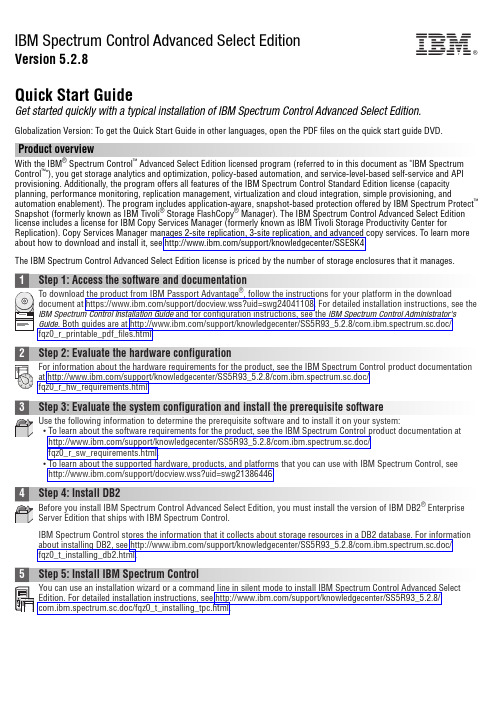
IBM Spectrum Control Advanced Select EditionVersion 5.2.8Quick Start GuideGet started quickly with a typical installation of IBM Spectrum Control Advanced Select Edition.Globalization Version: To get the Quick Start Guide in other languages, open the PDF files on the quick start guide DVD.Product overviewWith the IBM ®Spectrum Control ™Advanced Select Edition licensed program (referred to in this document as "IBM Spectrum Control ™"), you get storage analytics and optimization, policy-based automation, and service-level-based self-service and API provisioning. Additionally, the program offers all features of the IBM Spectrum Control Standard Edition license (capacity planning, performance monitoring, replication management, virtualization and cloud integration, simple provisioning, and automation enablement). The program includes application-aware, snapshot-based protection offered by IBM Spectrum Protect ™Snapshot (formerly known as IBM Tivoli ®Storage FlashCopy ®Manager). The IBM Spectrum Control Advanced Select Edition license includes a license for IBM Copy Services Manager (formerly known as IBM Tivoli Storage Productivity Center forReplication). Copy Services Manager manages 2-site replication, 3-site replication, and advanced copy services. To learn more about how to download and install it, see /support/knowledgecenter/SSESK4.The IBM Spectrum Control Advanced Select Edition license is priced by the number of storage enclosures that it manages.2Step 2: Evaluate the hardware configurationFor information about the hardware requirements for the product, see the IBM Spectrum Control product documentation at /support/knowledgecenter/SS5R93_5.2.8/com.ibm.spectrum.sc.doc/fqz0_r_hw_requirements.html.3Step 3: Evaluate the system configuration and install the prerequisite softwareUse the following information to determine the prerequisite software and to install it on your system:v To learn about the software requirements for the product, see the IBM Spectrum Control product documentation at /support/knowledgecenter/SS5R93_5.2.8/com.ibm.spectrum.sc.doc/fqz0_r_sw_requirements.html.v To learn about the supported hardware, products, and platforms that you can use with IBM Spectrum Control, see /support/docview.wss?uid=swg21386446.4Step 4: Install DB2Before you install IBM Spectrum Control Advanced Select Edition, you must install the version of IBM DB2®Enterprise Server Edition that ships with IBM Spectrum Control.IBM Spectrum Control stores the information that it collects about storage resources in a DB2 database. For information about installing DB2, see /support/knowledgecenter/SS5R93_5.2.8/com.ibm.spectrum.sc.doc/fqz0_t_installing_db2.html.5Step 5: Install IBM Spectrum ControlYou can use an installation wizard or a command line in silent mode to install IBM Spectrum Control Advanced Select Edition. For detailed installation instructions, see /support/knowledgecenter/SS5R93_5.2.8/com.ibm.spectrum.sc.doc/fqz0_t_installing_tpc.html.IBM®6Step 6: (Optional) Install Cognos Business Intelligence reportsThe IBM Spectrum Control installation includes the option to install IBM Cognos®Business Intelligence (BI) reports andthe components that are required to produce these reports: Jazz™for Service Management and IBM Tivoli Common Reporting. Cognos BI is an optional tool for producing scheduled reports from the data that is gathered by IBM Spectrum Control. You can use the reporting features in the IBM Spectrum Control GUI to produce reports about the status,capacity, and performance of the storage resources that you want to monitor without installing Cognos BI.For more information about Cognos BI reports, see /support/knowledgecenter/SS5R93_5.2.8/ com.ibm.spectrum.sc.doc/fqz0_c_webbasedgui_rpting_ic_ov.html. For information about the components that you must install to use Cognos BI reports, see /support/knowledgecenter/SS5R93_5.2.8/com.ibm.spectrum.sc.doc/fqz0_c_jazzsm_tcr.html.7Step 7: Get startedStarting and configuring IBM Spectrum Control includes these tasks:v Start the IBM Spectrum Control GUI. See /support/knowledgecenter/SS5R93_5.2.8/com.ibm.spectrum.sc.doc/fqz0_t_starting_tpc_web_based.html.v Add resources, for example, all storage systems, servers, hypervisors, fabrics, and switches. See/support/knowledgecenter/SS5R93_5.2.8/com.ibm.spectrum.sc.doc/tpch_t_wz_adding_resources.html.v Configure communication for alerts. See /support/knowledgecenter/SS5R93_5.2.8/com.ibm.spectrum.sc.doc/fqz0_t_configuring_alerts.html.v Set conditions for triggering alerts. See /support/knowledgecenter/SS5R93_5.2.8/com.ibm.spectrum.sc.doc/fqz0_r_triggering_conditions.html.To learn more about getting started with IBM Spectrum Control, see /support/knowledgecenter/ SS5R93_5.2.8/com.ibm.spectrum.sc.doc/fqz0_r_getting_started.html .More informationFor more information, see the following resources:v Product licenses and their feature offerings: /support/knowledgecenter/SS5R93_5.2.8/com.ibm.spectrum.sc.doc/fqz0_r_product_packages.htmlv General product information: /systems/storage/software/center/index.htmlv Product support: /support/entry/portal/Overview/Software/Tivoli/Tivoli_Storage_Productivity_Centerv Connect, learn, and share with Service Management professionals at: https:///developerworks/servicemanagement/sm/index.htmlIBM Spectrum Control Advanced Select Edition Version 5.2.8 Licensed Materials - Property of IBM. © Copyright IBM Corp. 2011, 2015. US Government Users Restricted Rights - Use, duplication or disclosure restricted by GSA ADP Schedule Contract with IBM Corp.IBM, the IBM logo, and ®are trademarks or registered trademarks of International Business Machines Corp., registered in many jurisdictions worldwide. Other product and service names might be trademarks of IBM or other companies. A current list of IBM trademarks is available on the web at “Copyright and trademark information” (/legal/copytrade.shtml).Part Number:CF4HSMLPrinted in Ireland。
datacolor paint 安装指南(独立系统)说明书

Datacolor PAINT INSTALLATION GUIDESTAND-ALONE SYSTEMSDatacolor PAINT Installation Guide Stand-Alone Systems(Part No. MF 59.1 December, 2007)All efforts have been made to ensure the accuracy of the information presented in this format. However, should any errors be detected, Datacolor appreciates your efforts to notify us of these oversights.Changes are periodically made to this information and are incorporated into forthcoming versions. Datacolor reserves the right to make improvements and/or changes in the product(s) and/or program(s) described in this material at any time.© 2007 Datacolor. Datacolor, SPECTRUM and other Datacolor product trademarks are the property of Datacolor.Microsoft and Windows are either registered trademarks of Microsoft Corporation in the United States and/or other countries.To obtain information on local agents, contact either of the offices listed below, or visit our website at .Support Questions?If you need help with a Datacolor product, please contact one of our top-rated technical support teams located around the world for your convenience. You can find contact information below for the Datacolor office in your area.Americas+1.609.895.7465+1.800.982.6496 (toll-free)+1.609.895.7404 (fax)************************Europe+41.44.835.3740+41.44.835.3749 (fax)************************Asia Pacific+852.2420.8606+852.2420.8320 (fax)************************Or Contact Your Local RepresentativeDatacolor has representatives in over 60 countries. For a complete list, visit/locations.Manufactured by Datacolor5 Princess RoadLawrenceville, NJ 086481.609.924.2189Committed to Excellence. Dedicated to Quality. Certified to ISO 9001 in Manufacturing Centers Worldwide.CONTENTSINTRODUCTION (4)O VERVIEW (4)Product Components (4)System Requirements (4)Data Backup (5)Firewall Blocking Messages (6)New Installations (6)Instrument Driver Selection (6)Program Upgrades (6)Installation Procedure Summary (7)DATACOLOR PAINT INSTALLATION (8)O VERVIEW (8)Before You Begin (8)Installation Procedure (8)D ATACOLOR PAINT P ROGRAM I NSTALLATION (9)D ATACOLOR PAINT U PGRADE (12)O THER D ATACOLOR PAINT I NSTALLATION O PTIONS (13)Install Instrument Drivers (13)Install Dispensers (13)Visit Datacolor on the Web (14)LICENSING DATACOLOR PAINT (15)O VERVIEW (15)Demonstration Period (15)Considerations (15)S OFTWARE L ICENSING P ROCEDURE (17)IntroductionOverviewDatacolor PAINT is an in-store custom color matching program. It formulates matches to new colors,and can retrieve formulas from a formula book or from a competitor’s fandeck. Datacolor PAINT includes a correction feature that provides suggestions for correcting a mistint, and an option that allows you to store and retrieve customer formulas.Datacolor PAINT can be installed on a dedicated, stand-alone computer system, or on a terminal server that is shared by several users.This installation guide covers the following procedures:•Installing Datacolor PAINT on a new, stand-alone system.•Validating the software license for Datacolor PAINT•Upgrading an existing stand-alone system from Datacolor Paintmaker to Datacolor PAINTNotes for New InstallationsIf you have purchased your computer from Datacolor, the installation and licensing is completed at the factory.If you purchased your own computer, you must use these instructions to install and license the software on your computer.Product ComponentsDatacolor PAINT consists of the following components:•Datacolor PAINT CD•Software License Number. This is found on a label on the back of the Datacolor PAINT CD.You will need this to complete the licensing procedure.System RequirementsThe system requirements shown below are the minimum configuration to ensure effective operation of the Datacolor PAINT.Component Minimum* RecommendedProcessor Pentium III 300 MHz Pentium IV 1.9 GHzMemory 128 MB 1 GBHard Drive Capacity 10 GB 40 GBVideo Resolution 800x600 16-bit 1024 x 768 True ColorVideo Memory 64 MB 128 MBCD/DVD Drive CD Reader CD WriterDiskette Drive -- 1.44MBAvailable Ports** 1 RS-2321 USB1 Parallel2 RS-232 6 USB1 ParallelOperating System Windows® 98 SE Windows® XP Homeor Pro* The minimum requirements may limit performance and the operation of some features.** The number of ports needed depends on the number of peripheral devices on the system.When selecting hardware and operating system features to support Datacolor PAINT, the followingrequirements may need to be considered:•Datacolor PAINT is supplied on a standard 650MB capacity compact disc (CD).•Datacolor spectrophotometers can be connected to either an RS-232 port or a universal serial bus (USB) port.•Instrument calibration data may be distributed on 1.44MB diskettes. The presence of this diskette drive will provide maximum operational flexibility.•Accurate on-screen color display requires a true-color video card, and the performance of monitor calibration at regular intervals. The Datacolor SPYDER2 monitor calibration devicerequires a connection to a USB port.•Printer port requirements (parallel or USB) depend on the specific printer selected.•For non-networked systems, a CD or DVD writer is recommended for use as a system backup.•Faster processors and hard drives, and larger memory capacity will significantly enhance performance.Data BackupIf you are currently using Datacolor Paintmaker or Datacolor PAINT, you should back up the data beforeperforming any type of upgrade or file conversion. The following files should be included in the backupprocedure:DatabaseFileExtensionDescriptionFormulation*.mdbfdt This database contains data that define a product line. It includesinformation about the systems, brands and colors contained in theproduct lines, along with ingredient and formula information.These files should each be copied to a new name before they areused.Illuminants*.mdbill Contains data that define the sources of illumination for use in colormatching.CustomerInformation*.mdb Contains all of the customer information that you have stored.Firewall Blocking MessagesIf you have installed a firewall on the system, you may see the dialog box below during the installation:−When this happens, you must click Unblock to continue the installation.New InstallationsDatacolor PAINT can be installed on a dedicated, stand-alone system, or on a terminal server. This guide covers the instructions required to install or upgrade Datacolor PAINT on a stand-alone system.Instrument Driver SelectionTwo instrument drivers are provided with Datacolor PAINT. The program automatically installs the Datacolor PAINT native driver. See also Datacolor PAINT User’s Guide for a discussion of the driver choices, and instructions for changing the driver used.Program UpgradesIf you are currently running Datacolor Paintmaker, Datacolor considers this an upgrade to Datacolor PAINT. This upgrade simply updates the Datacolor program. Below are some tips to keep in mind if you are upgrading from Datacolor Paintmaker to Datacolor PAINT v.1.x:•Upgrading a stand-alone system from Datacolor Paintmaker to Datacolor PAINT uses the same procedure as that used to install a new system.•If you are upgrading from Datacolor Paintmaker to Datacolor PAINT on a dedicated, stand-alone computer, you can continue using the hardware security key. In this situation you do nothave to perform the software license validation.•If you are upgrading from Paintmaker to Datacolor PAINT, and want to switch to the Datacolor SPECTRUM instrument driver, you must install the SPECTRUM driver separately. See alsoDatacolor PAINT User’s Guide, Appendix for a discussion of instrument driver choices, andinstructions to switch from the Paintmaker native driver to the Datacolor SPECTRUMinstrument driver.Installation Procedure SummaryBelow is a summary of the installation steps for both new installations and upgrades.Screen-by-screen instructions are provided in the section Installing Datacolor PAINT.New Installations1. Insert the Datacolor Paint installation CD, accept the user agreement, and make theappropriate language selection.2. You will be prompted to select the type of install you wish (Typical, or Custom). SelectTypical, and click Next. You will be prompted to restart your PC.3. You will be prompted to select a dispenser type. Make the selection, and click Next.4. When the installation is completed, you will be prompted to restart your PC. Restart thesystem, and when the PAINT installation menu displays, exit and remove the Datacolor Paint CD.5. Insert the manufacturer update CD, and follow the prompts to install.Upgrades to Datacolor Paint1. Insert the Datacolor Paint installation CD, accept the user agreement, and make theappropriate language selection.2. Once Datacolor Paint software has completed the installation, click Finish, and remove theDatacolor Paint software installation CD.3. Insert the manufacturer data/update CD. Follow the prompts to install.Datacolor PAINT InstallationOverviewYou may be installing the Datacolor PAINT program for the first time, or you may be upgrading from an existing version of Datacolor Paintmaker. This section provides screen-by-screen instructions to install the program. The program installation is the same for both new installations and for upgrades. Please follow these instructions EXACTLY, to insure successful installation of Datacolor PAINT.Before You Begin• A Windows operating system should be properly installed on your computer.•You must have Windows Administrator rights to install this software.•Close all other programs that are running.•Have the program CDs readily available. This includes the Datacolor PAINT CD, and the instrument calibration data disk. The calibration data is provided on both a diskette and a CD,and are shipped in the instrument tile box.•Backup any existing Paintmaker databases that you are currently using. See also Datacolor PAINT Upgrade in this guide for a list of the files that need to be protected.NOTEThe installation routine asks you to restart the computer several times. Be sure to restart yourcomputer whenever prompted.This guide provides instructions for installing, licensing and updating Datacolor PAINT on a stand-alone system. See also Datacolor PAINT Terminal Server Installation Instructions for a detailed explanationof the installation procedure for terminal servers.Installation ProcedureTo install the program on a stand-alone system you must complete the following steps: •Install PAINT program•License PAINT softwareDatacolor PAINT Program InstallationBelow are the instructions to install Datacolor PAINT:1. Exit all Windows programs. Insert the Paint CD into the CD-ROM drive. The installationshould begin automatically, and the Datacolor PAINT splash screen will be displayed:If the installation does not start automatically:−Go to Windows Start menu.− Select Run. The Dialog box below is displayed:Open field, enter <drive>:/Setup. The letter “d” in this example indicates that the CD is the− Indrive “d”. Your CD-Rom drive may have a different letter designation.− ClickOK.The Datacolor PAINT installation menu is displayed:Install Datacolor PAINT. The installation wizard will start and the screen below is on2. Clickdisplayed:You must have Windows Administrator Rights to install the programs:OK.3. ClickNext. The program will display a licensing agreement:4. ClickYes. The program will prompt you for a language selection:5. Click6. Click on the arrow to view the choices, and highlight a selection. Then click OK. The windowbelow is displayed:Typical Installation, and then click Next. Follow the on-screen directions. When the on7. Clickinstallation is complete, the program will prompt you to restart your computer.OK. When the computer restarts, the program prompts you again regarding your status 8. Clickas a Windows System Administrator.9. Click OK. Messages will display regarding the status of the installation. The program willthen prompt you for a dispenser selection:10. Click on the manufacturer of your automatic dispenser. If you do not have an automaticdispenser, click No Dispenser / Manual Dispenser.Next, and continue to follow the on screen instructions. The program will continue11. Clickdisplaying installation status messages, and notify you when the installation is completed. 12. Click Yes, to restart the system, and click OK.The system will restart, and the PAINT installation menu will display.Exit to close the installation menu.13. ClickDatacolor PAINT UpgradeIf you are upgrading an existing system from Datacolor Paintmaker to Datacolor PAINT, the installation procedure is the same as the New System Installation procedure. See also New System Installation for detailed instructions to complete the upgrade.NOTEIf you are upgrading, you can continue to use the hardware key. In this situation, the installation is complete. You do not need to validate the software license.Other Datacolor PAINT Installation OptionsThe Datacolor PAINT Installation Menu includes options that allow you to change the instrument driver you are using, and to add a dispenser to your system:Install Instrument DriversTwo instrument drivers are available for use with Datacolor PAINT. This option provides the ability to change the instrument driver you are currently using. See also Datacolor PAINT User’s Guide for a discussion of the instrument driver selection, and complete instructions to change the instrument driver.Install DispensersThis option enables you to connect a dispenser to the Datacolor PAINT matching system at any time.To access this option:1. Place the Datacolor PAINT in the CD drive. The Datacolor PAINT Installation Menu will bedisplayed:Install Dispenser Drivers. The installation wizard opens:2. ClickonThe program will prompt you for the type of dispenser connected to the system:3. Click in the radio button to select the dispenser. When the selection is made, click Next. Theprogram will install the correct drivers for the dispenser you have selected.When the installation is completed, the Datacolor PAINT Installation Menu will be displayed.4. Click on another i nstallation option, or click Exit to close the menu.Visit Datacolor on the WebThis option connects the user directly to the Datacolor website.Licensing Datacolor PAINTOverviewDatacolor PAINT v1.1 is protected from unauthorized use by a software license. The license is assigned to the computer, and you must license the software to use it. When the program is installed, you are given a 14-day demonstration period during which you can run the programs without a valid license. We strongly recommend that you validate all software licenses immediately after installing the software.NOTESLicenses cannot be transferred from one computer to another.If you are using a hardware key, you will not be prompted to license the software. You do not have to complete this validation procedure.If your hardware key fails, the program will immediately prompt you to validate the software license. If this happens, read this section carefully, and use the instructions in the section Software Licensing Procedure to validate the software license.Demonstration PeriodWhen the software is installed, the software license defaults to a demo configuration, which allows you program access for 14 days. The software license must be validated within the demonstration period.NOTESThe demonstration period starts when the program is launched for the first time. Please license the product immediately to avoid a work stoppage. If you fail to license the product during the demonstration period, you will not be able to run Datacolor PAINT when the demonstration period expires.During the demonstration period, Datacolor PAINT will display the Datacolor Security Client screeneach time it launches.ConsiderationsA license is validated when you enter an Unlock Response Number into the Datacolor Security Client window.This number is provided by Datacolor, and can be obtained one of three ways:web connection. If you have internet access, you can use the link provided in the • DirectDatacolor Security Client window. This procedure is documented in the Licensing Proceduresection of these instructions.•Email. For each product, send the Serial Number found on the CD label, and Computer Validation Number found on the Datacolor Security Client window, to*****************************. You will receive an Unlock Response Number via email.You must enter this into the Datacolor Security Client window.•Telephone. In the US and Canada phone toll free (1-800-982-6496) or call you local sales office. You will need the Serial Number and the Computer Validation Number for theproduct. You will be given an Unlock Response Number that you will put into the DatacolorSecurity Client window.Product Labels and Software LicensesThe Serial Number for Datacolor PAINT is supplied by Datacolor, and is found on the Datacolor PAINT CD.Shown below is a sample label for the product license Datacolor PAINT:Before You BeginYou will need the Datacolor PAINT CD case with the serial number for the product.•You will be asked for a Computer Validation Numbe r during this procedure. This number is generated by the security software and is unique to your computer. It is displayed on thevalidation screen, which is open throughout the validation procedure.•During the licensing process you will be provided with an Unlock Response Number. You will be required to input that number into this screen to complete the licensing process.NOTEWe recommend that you use the Windows Copy and Paste features to transfer the numbers from this validation screen to other input fields as required. This will eliminate licensing errors due to input errors.Upgrade Notes•If you are upgrading Datacolor PAINT, you can continue using the hardware security key.Datacolor PAINT recognizes either key. You will not be prompted to validate the softwarelicense when a hardware key is installed.•If your hardware key fails, you will immediately need to validate the software license. Contact Datacolor Support for assistance in performing this validation.Software Licensing ProcedureThe procedure detailed below is used to license the software via a direct web connection.NOTEIf you do not have an internet connection, call your Datacolor regional support office listed in the front of this guide to obtain the Unlock Response Number for your system. You must provide the serial number on the Datacolor PAINT CD case to the Datacolor personnel.1. Click on the Datacolor PAINT icon to launch the program.The Datacolor Security Client window will open:3.Click on the link to the web connection:The window below is displayed:This window provides an Internet connection to the Datacolor web validation service, and remains open during the validation procedure.− In the First Name , Last Name and Email fields, provide your contact information.In the Serial Number field, enter the product serial number again. It must match the number you entered in the previous screen.4. Click the Continue button. The window below is displayed:2. In the Serial Number field, enter the serial number for Datacolor PAINT. This is found on the CD label.NOTESThis screen remains open during the validation process. You will later be asked for theComputer Validation Number. We suggest that you return to this window, to copy and paste the Computer Validation Number . This will eliminate keyboarding errors.Selecting Continue , while in the demonstration period, will bypass the validation procedure and open the program.This window verifies that the serial number is valid, and displays information about the product.5. Click Continueto proceed. The program will prompt you for the computer validation number:6.Enter the computer validation number from the Datacolor Security Client window, and click Validate to continue. A number will be displayed in the Unlock Response Numberfield.7.Return to the Datacolor Security Client screen, and enter the Unlock Responsenumber:NOTEYou can copy the C omputer Validation number from the Datacolor Security Client screen, using the standard Windows Copy command. You can paste it here, using the Paste command.8.Return to the web validation screen. The validation process is completed, and DatacolorDatacolor PAINT is now licensed.9.To end the licensing procedure, click Close this Window.NOTEYou will receive an email confirmation containing the serial number and unlock response number for each license you validate. We recommend that you make copies of these for reference purposes.NOTEYou can copy the Unlock Response Number from the web validation screen using thestandard Windows Copy command, and paste it into this screen using the Paste command.。
msl数据集的预处理代码_示例及概述说明
msl数据集的预处理代码示例及概述说明1. 引言1.1 概述:在当今科技发展的时代,数据分析和机器学习等领域正变得越来越重要。
而在这些领域中,数据集的质量和准确性对于研究和应用的成功起着至关重要的作用。
MSL(Machine Symbolic Learning)数据集是一个被广泛使用和研究的公开数据集,其中包含了大量有关机器学习算法性能评估的信息。
本文旨在介绍MSL数据集的预处理代码示例,并提供详细说明。
通过本文,读者将能够了解如何进行MSL数据集的预处理,以及预处理过程中所需考虑的一些关键步骤和技巧。
本文还将提供一些用于数据清洗、特征工程以及标签处理等方面的代码示例,并以简洁明了的方式阐述其背后的原理。
1.2 文章结构:本文按照以下结构组织:首先,我们将在第2节介绍MSL数据集,并对其内容进行概述。
接下来,在第3节中,我们将详细介绍MSL数据集预处理过程中的第一部分步骤,并给出相关代码示例。
随后,在第4节中,我们将进一步探讨预处理过程中的第二部分步骤,同样提供相应的代码示例。
最后,在第5节中,我们将进行总结,并探讨进一步研究方向。
1.3 目的:本文的目的是为读者提供一个全面且易于理解的MSL数据集预处理指南,为从事机器学习和数据分析领域的研究人员和开发者们提供有价值的参考资料。
通过了解MSL数据集预处理过程中的关键步骤和示例代码,读者将能够更好地应用这些技术和工具来处理其他类似领域中的问题。
无论是初学者还是经验丰富的专业人士,本文都将有助于拓宽他们在数据预处理方面的知识和技能,进而在实际应用中取得更好的结果。
2. MSL数据集预处理代码示例2.1 数据集介绍在本节中,我们将介绍MSL(Mars Science Laboratory)数据集,该数据集是由NASA的Curiosity火星车通过其Mastcam仪器拍摄的一系列图像组成的。
这些图像被用于研究和探索火星表面的地质特征和环境。
2.2 预处理步骤一在本节中,我们将展示MSL数据集的预处理代码示例的第一步。
基于SSDT恢复的反恶意代码技术
基于SSDT恢复的反恶意代码技术陈萌【期刊名称】《计算机工程》【年(卷),期】2009(035)021【摘要】通过修改系统服务调度表(SSDT),恶意代码可以避免被杀毒软件或反恶意软件清除.针对SSDT挂钩技术,通过系统文件霞定位,实现基于SSDT恢复的反恶意代码技术,阐述Ntoskrnl.exe文件的重装方法和Nmskrnl.exe文件偏移比较法.实验结果证明,该技术能使恶意代码和木马程序失效,保障系统安全.%By amending System Service Dispatch Table(SSDT), the malicious code can avoid being cleared by antivirus software or anti-malice software. Aiming at SDDT hook technology, this paper realizes an anti-malicious code technology based on SSDT restoration through system file relocation. It expatiates the method of resetting Ntoskrnl.exe files and the method of shifting comparison of Ntoskml.exe files. Experimental results show that this technology can invalidate malicious codes and Trojan programs and guarantee system security.【总页数】3页(P128-130)【作者】陈萌【作者单位】宁波工程学院电子与信息工程学院,宁波,315016【正文语种】中文【中图分类】TP309.2【相关文献】1.恶意代码技术剖析 [J], 陈洁;刘克胜;单洪2.恶意代码技术剖析 [J], 陈洁;刘克胜;单洪3.Web应用程序客户端恶意代码技术研究与进展 [J], 黄玮;崔宝江;胡正名4.恶意软件治理:有始无终——访中国互联网协会反恶意软件协调工作组组长杨君佐 [J], 褚德坤;杨晨5.基于多态变形的恶意代码技术与检测方法 [J], 李榕因版权原因,仅展示原文概要,查看原文内容请购买。
MSI Planet Antenna File Format
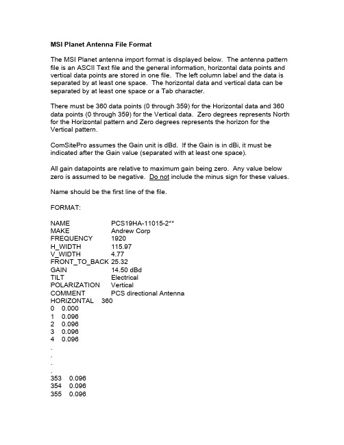
MSI Planet Antenna File FormatThe MSI Planet antenna import format is displayed below. The antenna pattern file is an ASCII Text file and the general information, horizontal data points and vertical data points are stored in one file. The left column label and the data is separated by at least one space. The horizontal data and vertical data can be separated by at least one space or a Tab character.There must be 360 data points (0 through 359) for the Horizontal data and 360 data points (0 through 359) for the Vertical data. Zero degrees represents North for the Horizontal pattern and Zero degrees represents the horizon for the Vertical pattern.ComSitePro assumes the Gain unit is dBd. If the Gain is in dBi, it must be indicated after the Gain value (separated with at least one space).All gain datapoints are relative to maximum gain being zero. Any value below zero is assumed to be negative. Do not include the minus sign for these values. Name should be the first line of the file.FORMAT:NAME PCS19HA-11015-2**MAKE Andrew CorpFREQUENCY 1920H_WIDTH 115.97V_WIDTH 4.77FRONT_TO_BACK 25.32GAIN 14.50 dBdTILT ElectricalPOLARIZATION VerticalCOMMENT PCS directional AntennaHORIZONTAL 3600 0.0001 0.0962 0.0963 0.0964 0.096....353 0.096354 0.096355 0.096356 0.096 357 0.096 358 0.096 359 0.096 VERTICAL 3600 1.4011 0.3002 0.0003 0.4004 1.8955 4.0966 8.2017 10.006....350 17.924 351 17.393 352 19.494 353 21.514 354 23.479 355 24.437 356 20.000 357 13.979 358 7.494 359 3.098。
Color iMatch操作手册

X—rite Color iQC/iMatch 电脑测配色系统操作手册杭州三锦科技有限公司2010年1月序言Color iQC/iMatch软件是美国爱色丽(X—Rite)企业颜色管理计划下主要组件之一,以工业用户为基础,提供合适的软/硬件工具,为大小客户及供应链提供精确简易的色彩管理方案。
此软件已得到包括Wal—Mart、Target、Ann Taylor、JCPenny、M&S等在内的国内外诸多大公司的认可,并指定其作为他们电子数据提交的有效途径。
爱色丽(X-Rite)公司成立与1958年,公司总部位于美国密歇根州大激流市,经过近五十年的发展,其产品和服务已覆盖全球100多个国家,在收购GretagMacbeth后,主要产品有CE7000A、Color i7、Color i5、SP系列、500系列等,广泛应用于纺织、印刷、塑料、涂料、包装、设计、汽车、摄影、视频、牙齿护理及医疗等行业。
其发展历程:1915 麦克贝斯(Macbeth)人工日光公司在纽约开业,向市内零售商提供日光照明设施。
1918 孟塞尔(Munsell)颜色公司在波士顿成立,生产带孟塞尔颜色体系标识的颜色标准. 1946 格灵达(Gretag)公司在瑞士成立。
1958 爱色丽(X-Rite)公司在美国密歇根州格兰维尔市成立。
1961 爱色丽开发出早期市场化产品,X射线记录条.1984 格灵达颜色控制系统研发出便携式分光光度仪。
1986 爱色丽在美国纳斯达克上市。
1993 爱色丽香港公司成立,开拓中国及亚洲业务。
1997 格灵达与麦克贝斯合并成为格灵达·麦克贝斯GretagMacbeth2001 格灵达麦克贝斯成为Amazys控股公司的子公司。
爱色丽上海公司成立。
2003 爱色丽中国维修服务中心在上海成立.2006 爱色丽收购Amazys (格灵达麦克贝斯的母公司)。
2007 爱色丽收购彩通(Pantone)公司。
电脑测配色系统染料数据库的建立及实践_李永光
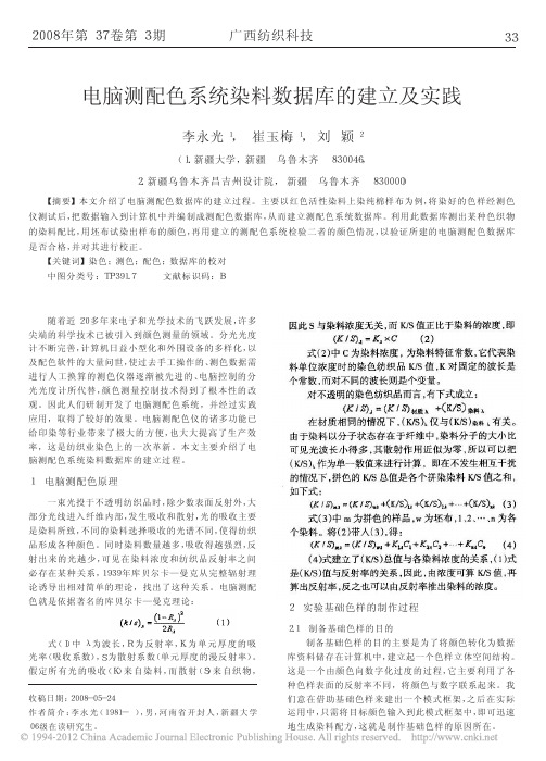
广西纺织科技
33
电脑测配色系统染料数据库的建立及实践
李永光 1, 崔玉梅 1, 刘 颖 2
( 1. 新疆大学, 新疆 乌鲁木齐 830046,
2. 新疆乌鲁木齐昌吉州设计院, 新疆 乌鲁木齐 830000)
【摘要】本文介绍了电脑测配色数据库的建立过程。主要以红色活性染料上染纯棉样布为例, 将染好的色样经测色
实验室中活性染料染色时采用低温染色。染色期间 要注意的是, 当采用同一种染料对布样分别进行不同浓 度梯度的上染时, 必须采用相同的工艺流程和染色温度。 2.4.1 活性染料上染工艺流程
本文所采用的染色工艺为浸染法, 其上染工艺流程 为, 在常温下上染 30min, 之后升温至 80℃并恒温保持 60min。之间在开始上 染 15min 后向染液中 加入助染 剂 NaCl, 在 升 至 80℃时 向 染 液 中 加 入 固 色 剂 Na3PO4, 加 入 NaCl 的量 应根据染色 深度、浴比、染 料 溶 解 度 和 染 料 的 亲和力等因素来决定, 而加入碱的量应根据染料的反应 性和染料用量来决定, 染料反应性强或用量低时可用较 少的碱。染色期间要每隔 2 ̄3min 搅拌染液一次, 以防坯 布染花, 在向染液加入盐、碱时要先将坯布取出, 加入盐、 碱并充分搅拌均匀后, 再将坯布放入染液当中, 并继续搅 拌。活性染料染色工艺流程图见图 1。
采用大孔测量, 必须保证色样将测量孔完全覆盖; 每块织物取着色均匀的 4 个不同位置测色, 取平均 值, 若是无正反面之分的织物, 两面各测两处, 有纹路的织 物测正面, 放置时纹路方向与实际目测对样方向一致; 测量时要对仪器进行正确的校验工作; 测色过程中, 测量口径处被测织物表面状态很重要, 要求尽量平整有序无褶皱, 同时要避开色花点和不均匀 处。 3.1 测配色数据库的建立过程 3.1.1 建立数据库的前期工作 首先打开电脑测配色仪预热 3min, 之后选择大孔径 进行测色, 选择大孔径是因为纺织品表面通常都较粗糙, 光线反射不规则, 因此要用较大的测量面积来测。 3.12 数据输入 数据输入按照以下步骤进行: 第一, 输入基础资料。在测配色仪器上测出一块空白 棉样的相关数据, 用做基础资料。 第二, 选择染料种类。在系统界面中选择实验室所用 的“染料种类”, 并为此染料起名, 如“reaction huoxing”。 第三, 录入数据。对各个染料浓度梯度下的布样分别 测色、记录并保存。填好布样的基本信息后, 将色样放在 测配色仪上测色, 再将生成 K/S 曲线图保存下来。同一染 料的各浓度梯度所对应的色样测完之后, 将会自动生成 一个含有颜色浓度由低到高排列的对话框。 第四, 选择加工程序。在系统主界面中选择“加工程 序”, 并为试验上染布样所采用的上染工艺起上名称。 第五, 创建染色组。点击系统主界面上的“染色组”对 象, 在出现的染色组窗体中填写好相关信息, 如: 名称、染 料 种 类 、主 要 加 工 程 序 等 等 并 保 存 。 第六, 设置混纺 比。 在系统 主 界 面 中 点 击“混 纺 比
一种改进的快速归一化积相关图像匹配算法
一种改进的快速归一化积相关图像匹配算法程红;陈文剑;孙文邦【摘要】The normalized cross correlation algorithm is a classic image matching algorithm. The method is simple and has a high matching probability. However, its disadvantage is enormous computation, which is difficult to meet the requirements of real-time. In this paper, first, a method for reducing the computation is proposed. By constructing two searching matrix from the reference image, the searching path of the real-time image is simplified. It completes the matching just along one translation direction and can avoid repetitious computation of the image energy easily based on an iterative operation between the two adjacent sub-based images. Then, the fast matching algorithm is proposed by combining the method and the bounded partial correlation (BPC) algorithm. It improves the computational speed of the algorithm by reducing computation from two aspects. Final, the experiment results show the superiorities of the algorithm.% 归一化积相关算法是一种经典的图像匹配算法,具有操作简单、匹配概率高等优点,其不足之处主要在于计算量大,难以满足实时性要求。
- 1、下载文档前请自行甄别文档内容的完整性,平台不提供额外的编辑、内容补充、找答案等附加服务。
- 2、"仅部分预览"的文档,不可在线预览部分如存在完整性等问题,可反馈申请退款(可完整预览的文档不适用该条件!)。
- 3、如文档侵犯您的权益,请联系客服反馈,我们会尽快为您处理(人工客服工作时间:9:00-18:30)。
RAL 6034 RAL 4003 RAL 6021 RAL 4006
● ● ●
SGM E10 SGM E11 SMC D162
Pastel green beige
RAL 6019 RAL 1001 RAL 5015
blue
2.2
body and GA tooling unique tooling
●
RAL 5024 松绿色 紫罗兰 暗绿色 紫色 粉绿色 米色 蓝色
● ● ● ●
L- Notch Back Die L-Hatch Back Die L-Station Wagon L-SGM618
Pastel turquoise Heather violet pale green traffic purple
blue
common tooling L-Plateform L-NB, L-HB L-SW L-SGM618
Pastel turquoise
●
松绿色 以松绿色为 底,不同的定 位夹紧处,涂 相应的颜色区 分
RAL 6034 RAL 6034 RAL 4003 RAL 3012 RAL 4006
Page 1
Pastel turquoise Heather violet pale green traffic purple
RAL 6034 RAL 4003 RAL 6021 RAL 4006
● ● ●
SGM E10 SGM E11 SMC D162
Pastel green beige
RAL 6019 RAL 1001 RAL 5015
2
Tooling Colors
Object
工装颜色
标识物 Die SGM-18模具 L-四门三厢车模具 L-五门二厢车模具 L-面包车模具 L-四门三厢改型车 L-四门三厢改型车 L-四门三厢改型车 SUV 焊接工装 专用工装 SGM-18工装
Color
颜色
Code
Remark
2.1 ●
模具 SGM-18 Die
●
SGM E10 SGM E11
以粉绿色为 底,不同的定 位夹紧处,涂 相应的颜色区 分
RAL 6019 RAL 1001
Page 2
备注
Page 3
Page 4
SGM-18 tooling
turquoise bule
青绿色 松绿色 紫罗兰 暗绿色 紫色 粉绿色 米色 蓝色
RAL 5018
● ● ● ●
L- Notch Back tooling L-四门三厢车工装 L-Hatch Back tooling L-Station Wagon L-SGM618 L-五门二厢车工装 L-面包车工装 L-四门三厢改型车 L-四门三厢改型车 L-四门三厢改型车 SUV 共用工装 L-平台 L-轿车系列 L-面包车系列
