TIM7785-8SL中文资料
7805中文资料
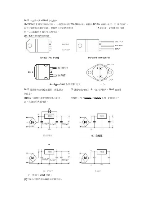
7805中文资料/LM7805中文资料LM7805是常用的三端稳压器, 一般使用的是TO-220封装,能提供DC 5V 的输出电压,应 用范围广,内含过流和过载保护电路。
带散热片时能持续提供 1A 的电流,如果使用外围器件,它还能提供不通的电压和电流。
LM7805引脚图(管脚图)(An^Type) 78W 系列管脚定义 十6=7805是常用的三端稳压器件,顾名思义05就是输出电压为 5v ,还可以微调,7805输出波纹很小。
(1)集成三端稳压器根据稳定电压的正、负极性分为78XXX, 79XXX 系列。
附图给出了正、负稳压的典型电路。
〈正、负稳压 7805电路〉(2)三端稳压器的型号规格和管脚分布。
VI»值)正霜压VII医I 正稳压 负稍压TO*220 (An/ T^pej 二OUTPUT二GROUMOau TPUTGROUND ISFUTGN JTO^20FF*rrO-22flFMOUTPUTINP芮MH F 0.1 A10 AI7MMfD3K FDlf7»M^3附表1 -17三端稳压器输出电流字母表示法萤寅祂示输出电圧雷字St?世册■出量£艷就(ft (MS 1-17)SV 右屣示正.熒电區硯対例如:78M05三端稳压器可输出+5 V 、0.5 A 的稳定电压;7912三端稳压器可输出 12V 、1A的稳定电压。
(3)外形及管脚分布,如附图 1-25所示。
由7805,7905,7812组成的特殊的线性稳压电源 如图所示为一种特殊的电源电路。
该电路虽然简单,但可以从两个相同的次级绕组中产生出三组直流电压:+5V 、-5V 和+12V 。
其特点是:D2、D3跨接在E2、E3这两组交流电源之 间,起着全波整流的作用。
人出A 出—输岀7812VoutGK D*12VVI竺出人输地输 人岀AC22O V50H^V QLI I;£Hx xS 02IO-2JQX【—轴人IXPUT ―地・GND3 v'lf'M orm r。
FLM7785-8F中文资料

C-Band Internally Matched FETFujitsu recommends the following conditions for the reliable operation of GaAs FETs:1. The drain-source operating voltage (V DS ) should not exceed 10 volts.2. The forward and reverse gate currents should not exceed 32.0 and -4.4 mA respectively with gate resistance of 100Ω.G.C.P.: Gain Compression Point, S.C.L.: Single Carrier LevelDESCRIPTIONThe FLM7785-8F is a power GaAs FET that is internally matched for standard communication bands to provide optimum power and gain in a 50 ohm system.Eudyna’s stringent Quality Assurance Program assures the highest reliability and consistent performance.FEATURES• High Output Power:P 1dB = 39.5dBm (Typ.)• High Gain:G 1dB = 8.5dB (Typ.)• High PAE:ηadd = 34% (Typ.)• Low IM 3= -46dBc@Po = 28.5dBm • Broad Band:7.7 ~ 8.5GHz• Impedance Matched Zin/Zout = 50Ω• Hermetically SealedC-Band Internally Matched FETPOWER DERATING CURVE20403010050100150200Case Temperature (°C)T o t a l P o w e r D i s s i p a t i o n (W)OUTPUT POWER & IM 3 vs. INPUT POWERV DS =10V f 1 = 8.5 GHz f 2 = 8.51 GHz 2-tone test141618202422Input Power (S.C.L.) (dBm)S.C.L.: Single Carrier Level242628303234-50-40-30-20O u t p u t P o w e r (S .C .L .) (d B m )IM 3P outI M 3 (d B c )OUTPUT POWER vs. FREQUENCYPin=31.5dBm29.5dBm27.5dBm25.5dBm 7.97.78.18.38.5Frequency (GHz)37383940413635O u t p u t P o w e r (d B m )V DS =10V P1dBV DS =10V f = 8.1 GHzOUTPUT POWER vs. INPUT POWER222426283032Input Power (dBm)363840423432303045150O u t p u t P o w e r (d B m )ηaddP outηa d d (%)C-Band Internally Matched FETS-PARAMETERSV DS = 10V , I DS = 2200mAFREQUENCY S11S21S12S22(MHZ)MAGANGMAGANGMAGANGMAGANG7500.402153.9 3.423133.7.094106.1.33195.47600.428137.7 3.344119.5.09193.1.34088.57700.440123.0 3.271105.2.09079.1.34382.87800.440110.3 3.21990.5.08964.6.34877.77900.42897.9 3.19675.9.08851.4.34572.88000.39586.5 3.20460.8.08739.0.34767.18100.34273.5 3.24444.5.08821.9.35461.18200.25761.1 3.29926.9.091 6.3.35252.68300.13246.2 3.3457.5.093-11.8.33141.78400.038-156.8 3.324-14.4.095-33.4.28427.28500.248-171.2 3.168-38.6.091-56.7.1860.08600.462169.6 2.817-63.6.083-81.0.069-59.78700.634150.62.337-87.2.068-104.4.147-164.20-j50S 0°S 21S 12C-Band Internally Matched FETEudyna Devices Inc. products contain gallium arsenide(GaAs) which can be hazardous to the human body and the environment. For safety, observe the following procedures:CAUTION• Do not put this product into the mouth.• Do not alter the form of this product into a gas, powder, or liquidthrough burning, crushing, or chemical processing as these by-products are dangerous to the human body if inhaled, ingested, or swallowed.• Observe government laws and company regulations when discarding this product. This product must be discarded in accordance with methods specified by applicable hazardous waste procedures.For further information please contact:Eudyna Devices USA Inc.2355 Zanker Rd.San Jose, CA 95131-1138, U.S.A.TEL:(408) 232-9500FAX:(408) 428-9111Eudyna Devices Europe Ltd.Network House Norreys DriveMaidenhead, Berkshire SL6 4FJ United KingdomTEL:+44 (0) 1628 504800FAX:+44 (0) 1628 504888Eudyna Devices Asia Pte Ltd.Hong Kong BranchRm.1101, Ocean Centre, 5 Canton Rd.Tsim Sha Tsui, Kowloon, Hong Kong TEL:+852-2377-0227FAX:+852-2377-3921Eudyna Devices Inc.Sales Division1, Kanai-cho, Sakae-kuY okohama, 244-0845, Japan TEL:+81-45-853-8156FAX:+81-45-853-8170Eudyna Devices Inc.reserves the right to change products and specifications without notice.The information does not convey any license under rights of Eudyna Devices Inc.or others.©2004 Eudyna Devices USA Inc.Printed in U.S.A.。
78,79系列三端稳压器器件资料

7805 790578XX系列集成稳压器的典型应用电路如下图所示,这是一个输出正5V直流电压的稳压电源电路。
IC采用集成稳压器7805,C1、C2分别为输入端和输出端滤波电容,RL为负载电阻。
当输出电较大时,7805应配上散热板。
下图为提高输出电压的应用电路。
稳压二极管VD1串接在78XX稳压器2脚与地之间,可使输出电压Uo得到一定的提高,输出电压Uo为78XX稳压器输出电压与稳压二极管VC1稳压值之和。
VD2是输出保护二极管,一旦输出电压低于VD1稳压值时,VD2导通,将输出电流旁路,保护7800稳压器输出级不被损坏。
下图为输出电压可在一定范围内调节的应用电路。
由于R1、RP电阻网络的作用,使得输出电压被提高,提高的幅度取决于R P与R1的比值。
调节电位器RP,即可一定范围内调节输出电压。
当RP=0时,输出电压Uo等于78XX稳压器输出电压;当RP逐步增大时,Uo也随之逐步提高。
下图为扩大输出电流的应用电路。
VT2为外接扩流率管,VT1为推动管,二者为达林顿连接。
R1为偏置电阻。
该电路最大输出电流取决于VT2的参数。
下图为提高输入电压的应用电路。
78XX稳压器的最大输入电压为35V(7824为40V),当输入电压高于此值时,可采用下图所示的电路。
VT、R1和VD组成一个预稳压电路,使得加在7800稳压器输入端的电压恒定在VD的稳压值上(忽略VT的b-e结压降)。
Ui端的最大输入电压仅取决于VT的耐压。
集成稳压器还可以用作恒流源。
下图为78XX稳压器构成的恒流源电路,其恒定电流Io等于78XX稳压器输出电压与R1的比值。
79XX系列集成压器是常用的固定负输出电压的三端集成稳压器,除输入电压和输出电压均为负值外,其他参数和特点与78XX系列集成稳压器相同。
79XX系列集成稳压的三个引脚为:1脚为接地端,2脚为输入端,3脚为输出端。
79XX系列集成稳压器的应用电路也很简单。
下图所示为输出-5V直流电压的稳压电源电路,IC采用集成稳压器7905,输出电流较大时应配上散热板。
东芝功放管资料

38
TIM1414-5-252
5
TIM1414-5L TIM1414-4UL NEW TIM1414-4LA TIM1414-4-252
TIM8596-4 TIM0910-4
NEW
TIM1213-4L TIM1011-4L TIM1011-4UL
NEW
36
TIM1213-4UL
TIM1011-2UL TIM8596-2 TIM0910-2 TIM1011-2L TIM1112-2
7
8
9
4
Output Power at 1dB Gain Compression (dBm)
40 Output Power at 1dB Gain Compression (W)
46
X-, Ku-band Internally Matched Power GaAs FETs/GaN HEMTs Pout vs. Frequency Map
5
■ GaN HEMTs
C-band Internally Matched Power GaN HEMT
BIAS CONDITIONS FREQUENCY BAND (GHz) 7.7-8.5
NEW 7-AA06A 7-AA04A
(Ta = 25 °C)
RF PERFORMANCE SPECIFICATIONS ABSOLUTE MAXIMUM RATINGS ELECTRICAL CHARACTERISTICS (TYP.) Tch (°C) 250 VGSoff (V) – 4.0 PACKAGE CODE IDS (@Pin = 44.0 dBm) (A) TYP. 10.0 MAX. 12.0 G✽✽ (dB) MAX. ±0.8 Tch✽ (°C) MAX. 140 50 – 10 18.0
TIM7785-16SL中文资料
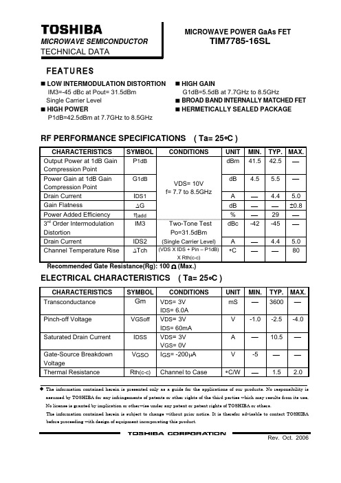
MICROWAVE POWER GaAs FETMICROWAVE SEMICONDUCTOR TIM7785-16SLTECHNICAL DATAFEATURESLOW INTERMODULATION DISTORTION HIGH GAINIM3=-45 dBc at Pout= 31.5dBm G1dB=5.5dB at 7.7GHz to 8.5GHz Single Carrier Level BROAD BAND INTERNALLY MATCHED FET HIGH POWERHERMETICALLY SEALED PACKAGEP1dB=42.5dBm at 7.7GHz to 8.5GHzRF PERFORMANCE SPECIFICATIONS ( Ta= 25°C )CHARACTERISTICS SYMBOL CONDITIONS UNITMIN. TYP.MAX. Output Power at 1dB Gain Compression PointP 1dB dBm 41.5 42.5⎯Power Gain at 1dB Gain Compression Point G 1dB dB 4.5 5.5 ⎯ Drain Current I DS1 A⎯4.45.0 Gain Flatness ΔGdB ⎯ ⎯±0.8 Power Added Efficiency ηadd VDS= 10V f= 7.7 to 8.5GHz% ⎯ 29 ⎯3rd Order Intermodulation Distortion IM3 dBc -42 -45 ⎯ Drain Current IDS2 Two-Tone Test Po=31.5dBm(Single Carrier Level) A ⎯4.45.0 Channel Temperature Rise ΔTch (VDS X IDS + Pin – P1dB)X Rth(c-c)°C ⎯ ⎯80 Recommended Gate Resistance(Rg): 100 Ω (Max.)ELECTRICAL CHARACTERISTICS ( Ta= 25°C )CHARACTERISTICS SYMBOL CONDITIONSUNITMIN. TYP.MAX.TransconductanceGm V DS = 3V I DS = 6.0AmS ⎯ 3600⎯ Pinch-off Voltage V GSoff V DS = 3VI DS = 60mAV -1.0 -2.5-4.0 Saturated Drain Current I DSS V DS = 3VV GS = 0VA⎯10.5⎯ Gate-Source Breakdown Voltage V GSO I GS = -200μA V -5 ⎯ ⎯Thermal Resistance R th(c-c) Channel to Case°C/W⎯1.52.0The information contained herein is presented only as a guide for the applications of our products. No responsibility is assumed by TOSHIBA for any infringements of patents or other rights of the third parties which may results from its use, No license is granted by implication or otherwise under any patent or patent rights of TOSHIBA or others.The information contained herein is subject to change without prior notice. It is therefor advisable to contact TOSHIBA before proceeding with design of equipment incorporating this product.ABSOLUTE MAXIMUM RATINGS ( Ta= 25°C )CHARACTERISTICS SYMBOL UNITRATINGDrain-Source Voltage V DS V 15 Gate-Source Voltage V GS V -5 Drain CurrentI DS A 14.0 Total Power Dissipation (Tc= 25 °C) P T W 75 Channel Temperature T ch °C 175 Storage TemperatureT stg°C-65 to +175PACKAGE OUTLINE (2-16G1B)Unit in mm (1) Gate (2) Source (3) DrainHANDLING PRECAUTIONS FOR PACKAGE MODELSoldering iron should be grounded and the operating time should not exceed 10 seconds at 260°C.RF PERFORMANCEOutput Power (Pout) vs. Frequency43 42 41 P o u t (d B m )407.77.98.18.38.5Frequency (GHz)Output Power(Pout) vs. Input Power(Pin)4544 43 PoutηaddPin(dBm)4241 40 39 38 37 36P o u t (d B m )80 70 ηa d d (%)60 50 40 30 201029 31 33 35 37 39POWER DISSIPATION vs. CASE TEMPERATURE906030 0 0 40 80 120 160 200Tc (°C)P T (W )IM3 vs. Output Power Characteristicsf=5MHz27-10-20 -30-40 -50 -60 I M 3(d B c )29 31 33 35 37 Pout(dBm) @Single carrier level。
LM7805中文资料

内部结构框图
绝对最大参数值
参数 输入电压(V0=5V~18V)(V0=24V)
热敏电阻接线外壳(Junction cases)(TO-220) 热敏电阻空气接头(Junction-Air) 工作温度范围 存储温度范围
符号 VI VI
RθJC RθJC TOPR TSTG
数值 35 40 5 65 0~+125 -65~+150
4.8 5.0 5.2
V
4.75 5.0 5.25
15W
VI = 7V ~ 20V
电压调整率
Regli TJ=+25 ℃ ne
Vo=7V~25V VI=8V~12V
- 4.0 100 mV - 1.6 50
负载调整率
Regl TJ=+25℃ aod
Io = 5.0mA ~1.5A
-
9 100 mV
Io=250mA
的脉冲测试使用的是负载。
电气特性(MC7806)
(涉及测试电路,0℃< TJ < 125℃, Io= 500mA,VI =11V, CI= 0.33μF,CO= 0.1μF,除非另有说
明)
参数
符号
状态
MC7806
单位
最 Typ 最
小
大
值
值
输出电压
VO TJ=+25℃
5.7 6.0 6.2
V
5.0mA ≤Io≤ 1.0A, PO≤15W,
5
5
5.7 6.0 6.3
VI = 8.0V ~ 21V
电压调整率 Regline TJ=+25℃ VI=8V~25V
- 5 120 mV
VI=9V~13V
ADE7758中文

斯美国模拟器件公司(ADI)ADE7758三相多功能电能计量IC (含各相信息)目录特征概述功能模块技术指标时序特征时序图表极限参数静电放电(ESD)警告引脚配置和功能描述术语典型性能特征测试电路工作原理防混叠滤波器模拟输入电流通道模数转换器(ADC)di/dt电流传感器和数字积分器峰值电流检测过载电流检测中断电压通道模数转换器(ADC)过零检测相位补偿周期测量线电压骤降(SAG)检测骤降电平设定峰值电压检测相序检测电源监视基准电路温度测量有效值计量有功功率计算无功率计算视在功率计算电能寄存比例波形采样模式校准校验和寄存器中断与MCU配合使用中断中断时序串行接口串行写入操作串行读取操作访问片内寄存器寄存器通讯寄存器操作模式寄存器(0x13)测量模式寄存器(1×14)波形模式寄存器(0×15)计算模式寄存器(0×16)线循环累加模式寄存器(0×17)中断屏蔽寄存器(0×18)中断状态寄存器(0×19)/复位中断状态寄存器(0×1A)外部尺寸定购指南历史修改记录2005年11月由版本A修改为版本B2004年9月由版本0修改为版本A修改表1 修改十六进制计数法修改图23的标题修改特征表修改电流波形增益寄存器部分修改规格表修改di/dt电流感应器和数字积分器部分修改图25修改相位补偿部分增加模拟输入部分的内容修改图57 增加图36-37,后面的图片重新排序修改图60 修改周期测量部分修改温度测量部分和有效值测量部分修改峰值电压检测部分插入表6 增加图60修改电流有效值偏移补偿部分修改电流有效值偏移补偿部分,编辑有功功率频率输出部分插入表7 增加图68,后面的图片重新排序增加公式17 修改无功功率频率输出部分修改电能累加模式部分增加图73,后面的图片重新排序修改无功功率计算部分修改使用脉冲输出进行增益校准例子增加公式32 修改公式37修改电能累加模式部分修改使用脉冲输出进行相位A的样本对相位校准修改无功功率频率输出部分修改公式56-57修改视在电能计算部分增加ADE7758中断部分修改校准部分修改有效值偏移样本对校准部分修改图76-图84 增加表20的内容修改表15修改表16修改定购指南特点高准确度:支持IEC60687,IEC61036,, IEC 61268, IEC 62053-21, IEC 62053-22, 和IEC 62053-23标准。
LM7805C中文资料

TO-3 Package K TO-220 Package T
150˚C 150˚C −65˚C to +150˚C
300˚C 230˚C
Electrical Characteristics LM78XXC (Note 2)
VO
Output Voltage
Tj = 25˚C, 5 mA ≤ IO ≤ 1A
4.8 5 5.2 11.5 12 12.5 14.4 15 15.6
PD ≤ 15W, 5 mA ≤ IO ≤ 1A
4.75
5.25 11.4
12.6 14.25
15.75
VMIN ≤ VIN ≤ VMAX
(7.5 ≤ VIN ≤ 20)
25
60
75
∆VIN
(8 ≤ VIN ≤ 12) (16 ≤ VIN ≤ 22) (20 ≤ VIN ≤ 26)
∆VO
Load Regulation Tj = 25˚C 5 mA ≤ IO ≤ 1.5A
10 50
12 120
12 150
250 mA ≤ IO ≤ 750 mA
25
60
75
5 mA ≤ IO ≤ 1A, 0˚C ≤ Tj ≤ +125˚C
LM78XX Series Voltage Regulators
元器件交易网
May 2000
LM78XX Series Voltage Regulators
General Description
The LM78XX series of three terminal regulators is available with several fixed output voltages making them useful in a wide range of applications. One of these is local on card regulation, eliminating the distribution problems associated with single point regulation. The voltages available allow these regulators to be used in logic systems, instrumentation, HiFi, and other solid state electronic equipment. Although designed primarily as fixed voltage regulators these devices can be used with external components to obtain adjustable voltages and currents.
LHI778中文资料
产品描述
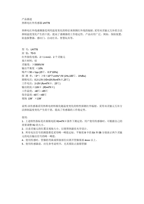
热释电红外传感器LHI778
热释电红外线感测器是利用温度变化的特征来探测红外线的辐射,采用双灵敏元互补的方法抑制温度变化产生的干扰,提高了感测器的工作稳定性。
产品应用广泛,例如,保险装置,防盗报警器,感应门,自动灯具,智慧玩具等。
型号:LHI778
封装:TO-5
红外接收电极:2×1 mm2,2个灵敏元
基片材料:硅
灵敏度:≥3300V/W
输出平衡度<10%
噪声≤50μVpp (25℃,0.3^10Hz)
探测率:(D*)≥5×10^7 cmHz^/W (1Hz,100℃,1HzBw)
源极电压:0.2-1.5V (VD=10V,Rs=47kΩ,25℃)
工作电压:2-15V (Rs=47KΩ,25℃)
输出阻抗:≤10KΩ(RS=47KΩ)
工作温度:-40℃- +85℃
保存温度: -40℃- +85℃
视场139°×139°
说明:该传感器采用热释电材料极化随温度变化的特性探测红外辐射,采用双灵敏元互补方法抑制温度变化产生的干扰,提高了传感器的工作稳定性。
使用:
1、上述特性指标是在源极电阻R2=47KΩ条件下测定的,用户使用传感器时,可根据自己的需要调整R2的大小。
2、注意灵敏元的位置及视场大小,以便得到最佳光学设计。
3、所有电压信号的测量都是采用峰一峰值定标。
平衡度B中的EA和EB分别表示两个灵敏元的电压输出信号的峰一峰值。
4、使用传感时,管脚的弯曲或焊接部位应离开管脚基部4mm以上。
5、使用传感器前,应先参考说明书,尤其要防止接错管脚。
QS7785中文资料
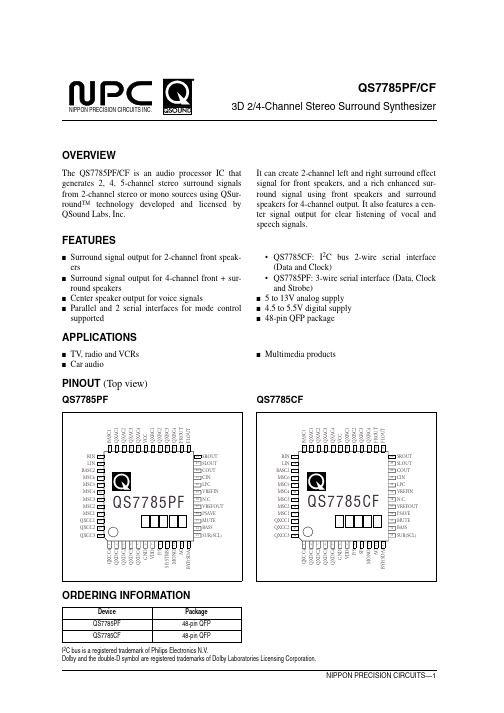
BYP(SDA) 12
ORDERING INFORMATION
Device QS7785PF QS7785CF
Package 48-pin QFP 48-pin QFP
I2C bus is a registered trademark of Philips Electronics N.V. Dolby and the double-D symbol are registered trademarks of Dolby Laboratories Licensing Corporation.
–
SCL
BASS
MUTE
PSAVE
VREFOUT
NC
VREFIN
LPC
CIN
COUT
SLOUT
SROUT
FLOUT
FROUT
QXBC4
QXBC3
QXBC2
QXBC1
VCC
QXAC4
QXAC3
QXAC2
QXAC1
BASC1
QS7785PF/CF
I/O
Description
O QEXPANDER C capacitor 4 I QEXPANDER D capacitor 1 O QEXPANDER D capacitor 2 I QEXPANDER D capacitor 3 O QEXPANDER D capacitor 4 – Ground – 4.5 to 5.5V digital supply I Input mode control (HIGH: parallel, LOW: serial) I Enhancement control (HIGH: high spread, LOW: low spread) I Serial data strobe (not applicable to QS7785CF) I Mono-to-stereo convert select (HIGH: mono to stereo mode, LOW: normal mode) I Center output control (HIGH: center on, LOW: center off) I Bypass control (HIGH: bypass, LOW: Qsurround) I/O Serial data input (also serves as ACK signal output for I2C bus) I Surround speaker control (HIGH: surround speaker on, LOW: off) I Serial clock signal input I Bass boost mode control (HIGH: bass boost on, LOW: bass boost off) I Mute signal control (HIGH: mute on, LOW: mute off) I Power save control (HIGH: power save on, LOW: power save off) O VCC/2 reference voltage output – No connection I VCC/2 reference voltage output (biased internally to VCC/2) I Center output lowpass filter I COUT output signal feedback input for front-channel output O Center signal output O Surround left-channel signal output O Surround right-channel signal output O Front left-channel signal output O Front right-channel signal output O QEXPANDER B capacitor 4 I QEXPANDER B capacitor 3 O QEXPANDER B capacitor 2 I QEXPANDER B capacitor 1 – 5 to 13V DC analog supply O QEXPANDER A capacitor 4 I QEXPANDER A capacitor 3 O QEXPANDER A capacitor 2 I QEXPANDER A capacitor 1 I Bass boost right-channel signal input
LM7805ACT中文资料

Regline
TJ = 25qC
VI = 8V to 25V VI = 9V to 13V
–
5.0
120
mV
–
1.5
60.0
Load Regulation (Note 4)
Regload
TJ = 25qC
IO = 5mA to 1.5mA
–
IO = 250mA to 750mA
–
9.0
120
mV
VO = 7V to 25V VI = 8V to 12V
–
4.0
100
mV
–
1.6
50.0
Load Regulation
Regload
TJ = 25qC
IO = 5mA to 1.5mA
–
IO = 250mA to 750mA
–
9.0
100
mV
4.0
50.0
Quiescent Current
IQ
Note 1: Absolute maximum ratings are those values beyond which damage to the device may occur. The datasheet specifications should be met, without exception, to ensure that the system design is reliable over its power supply, temperature, and output/input loading variables. Fairchild does not recommend operation outside datasheet specifications.
MT7885规格书-中文 _Rev1.15
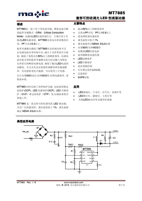
应用
LED球泡灯,日光灯,信号灯,景观灯等 LED舞台灯,蜡烛灯,玉米灯等 其他LED驱动应用及通用恒流源
典型应用电路
B7 Vin_ac R3 C1 F1 C12 Rst21 R1 Rst22 Rst1 L1 R4 CO
VLED+ VLED-
D1
MT7885
4 TM 3 VCC 2 OVP 1
D1 Rst21 R1 Rst22
MT7885
4 TM 3 VCC 2 OVP 1
DRAIN DRAIN NC CS
5 6 7 8 Rcs
C2
R2GNDU1源自开路保护的设置要注意几点: 1) 为方便设计,需使电阻由Rst21和Rst22相 等,即Rst21=Rst22,以达到平均分摊采样电压的 作用, 用于过压保护OVP值的设定。 Rst21和Rst22 的取值在150K欧姆~400K欧姆之间。如果需要支 持的母线电压偏低,则电阻Rst21和Rst22取值要 小;反之,则可以大一些,以提高系统效率。 2) 受分压电阻串R1, R2的精度影响, 以及芯 片内部参考电平的精度影响,公式(6)计算得到 的OVP阈值与实际的OVP阈值有一定的误差。准 确的OVP值可以通过调节R2的阻值来达到。OVP 值偏低,应该减小R2阻值;反之,则应加大R2的 阻值。建议R2初值取4.7K欧姆左右,用公式(6) 来确定R1的阻值,然后微调R2来精确确定OVP 值。 3) 建议将开路保护阈值设置在系统最大的
管脚描述
管脚名称 GND OVP VCC TM DRAIN NC CS 管脚号 1 2 3 4 5/6 7 8 芯片地 开路保护设置引脚及线电压采样补偿引脚 芯片电源,内部限压 15.5V 测试引脚,应用时必须悬空。 内部高压功率MOS管漏极 悬空脚 电流采样端,接采样电阻到地 描述
UTCLM7805中文资料

UTC LM78XXLINEAR INTEGRATED CIRCUITUTC UNISONIC TECHNOLOGIES CO., LTD.1QW-R101-006,C3-TERMINAL 1A POSITIVE VOLTAGE REGULATORDESCRIPTIONThe UTC 78XX family is monolithic fixed voltageregulator integrated circuit. They are suitable for applications that required supply current up to 1 A.FEATURES*Output current up to 1.5 A*Fixed output voltage of 5V, 6V, 8V, 9V, 10V, 12V, 15V ,18V and 24V available*Thermal overload shutdown protection *Short circuit current limiting*Output transistor SOA protection1: Input 2: GND 3: OutputTEST CIRCUITINPUTZ1UTC LM78XXLINEAR INTEGRATED CIRCUITUTC UNISONIC TECHNOLOGIES CO., LTD.2QW-R101-006,CABSOLUTE MAXIMUM RATINGS( Operating temperature range applies unless otherwise specified )PARAMETER SYMBOL RATING UNITInput voltage(for Vo=5~18V)(for Vo=24V) V I 35 40V V Output CurrentI o 1 A Power DissipationPD Internally Limited W Operating Junction Temperature RangeT OPR-20+150°CStorage Temperature Range T STG -55+150 °C UTC LM7805 ELECTRICAL CHARACTERISTICS( VI=10V, Io=0.5A, Tj= 0°C - 125°C, C1=0.33uF, Co=0.1uF, unless otherwise specified )(Note 1)PARAMETERSYMBOLTEST CONDITIONSMINTYP MAX UNITTj=25°C, I O =5mA - 1.0A4.805.0 5.20 VOutput Voltage VoV I =7.5V to 20V, I O =5mA - 1.0A,PD<15W4.755.25 V Load Regulation∆Vo Tj =25°C,I O =5mA - 1.5A 50 mVTj=25°C,I O =0.25A - 0.75A 25 mVLine regulation ∆Vo V I =7V to 25V,Tj=25°C 50 mVV I =7.5V to 20V,Tj=25°C,Io=1A 50 mV Quiescent Current Iq Tj=25°C, I O =<1A 8.0 mAQuiescent Current Change ∆Iq V I =7.5V to 20V 1.0 mA∆Iq I O =5mA - 1.0A 0.5 mA Output Noise Voltage V N 10Hz<=f<=100kHz 40 µV Temperature coefficient of Vo ∆Vo/∆T Io =5mA -0.6mV/°C Ripple Rejection RR V I =8V - 18V,f=120Hz,Tj=25°C 6280 dB Peak Output Current I PK Tj=25°C 1.8 A Short-Circuit Current I SC VI=35V, Tj=25°C 250 mA Dropout Voltage Vd Tj=25°C 2.0 VUTC LM7806 ELECTRICAL CHARACTERISTICS( VI=11V, Io=0.5A, Tj= 0°C - 125°C, C1=0.33uF, Co=0.1uF, unless otherwise specified )(Note 1)PARAMETERSYMBOLTEST CONDITIONSMINTYP MAX UNITTj=25°C, I O =5mA - 1.0A5.766.0 6.24 V Output VoltageVoV I =8.5V to 21V,I O =5mA - 1.0A, PD<15W5.706.30 VLoad Regulation∆Vo Tj =25°C,I O =5mA - 1.5A 60 mVTj=25°C,I O =0.25A - 0.75A 30 mVLine regulation ∆Vo V I =8V to 25V,Tj=25°C 60 mVV I =8.5V to 21V,Tj=25°C,Io=1A 60 mV Quiescent Current Iq Tj=25°C, I O =<1A 8.0 mAQuiescent Current Change ∆Iq V I =8.5V to 21V 1.0 mA∆Iq I O =5mA - 1.0A 0.5 mA Output Noise Voltage V N 10Hz<=f<=100kHz 45 µV Temperature coefficient of Vo ∆Vo/∆T Io =5mA -0.7mV/°C Ripple RejectionRR V I =9V - 19V,f=120Hz,Tj=25°C 5975 dBUTC LM78XXLINEAR INTEGRATED CIRCUITUTC UNISONIC TECHNOLOGIES CO., LTD.3QW-R101-006,CPARAMETERSYMBOLTEST CONDITIONSMINTYP MAX UNITPeak Output Current I PK Tj=25°C 1.8 AShort-Circuit Current I SCVI=35V, Tj=25°C 250 mA Dropout Voltage VdTj=25°C 2.0 VUTC LM7808 ELECTRICAL CHARACTERISTICS( VI=14V, Io=0.5A, Tj= 0°C - 125°C, C1=0.33uF, Co=0.1uF, unless otherwise specified )(Note 1)PARAMETERSYMBOL TEST CONDITIONSMINTYP MAX UNITTj=25°C, I O =5mA - 1.0A 7.688.0 8.32 V Output VoltageVoV I =10.5V to 23V,I O =5mA - 1.0A, PD<15W7.608.40 VLoad Regulation ∆Vo Tj =25°C,I O =5mA - 1.5A 80 mVTj=25°C,I O =0.25A - 0.75A 40 mVLine regulation ∆Vo V I =10.5V to 25V,Tj=25°C 80 mVV I =10.5V to 23V,Tj=25°C,Io=1A 80 mV Quiescent Current Iq Tj=25°C, I O =<1A 8.0 mAQuiescent Current Change ∆Iq V I =10.5V to 23V 1.0 mA ∆Iq I O =5mA - 1.0A 0.5 mAOutput Noise Voltage V N 10Hz<=f<=100kHz 58 µVTemperature coefficient of Vo ∆Vo/∆T Io =5mA -0.9mV/°C Ripple Rejection RR V I =11.5V to 21.5V, f=120Hz,Tj=25°C 5672 dBPeak Output Current I PK Tj=25°C 1.8 A Short-Circuit Current I SC VI=35V, Tj=25°C 250 mA Dropout Voltage Vd Tj=25°C 2.0 VUTC LM7809 ELECTRICAL CHARACTERISTICS( VI=15V, Io=0.5A, Tj= 0°C - 125°C, C1=0.33uF, Co=0.1uF, unless otherwise specified )(Note 1)PARAMETERSYMBOLTEST CONDITIONSMINTYP MAX UNITTj=25°C, I O =5mA - 1.0A8.649.0 9.36 VOutput Voltage VoV I =11.5V to 24V, I O =5mA - 1.0A,PD<15W8.55 9.45 V Load Regulation ∆Vo Tj =25°C,I O =5mA - 1.5A 90 mVTj=25°C,I O =0.25A - 0.75A 45 mVLine regulation ∆Vo V I =11.5V to 25 V, Tj=25°C, PD<15W90 mVV I =11.5V to 24V,Tj=25°C, Io<=1A90 mV Quiescent Current Iq Tj=25°C, I O =<1A 8.0 mAQuiescent Current Change ∆Iq V I =11.5V to 24V 1.0 mA∆Iq I O =5mA – 1.0A 0.5 mA Output Noise Voltage V N 10Hz<=f<=100kHz 58 µV Temperature coefficient of Vo ∆Vo/∆T Io =5mA -1.1 mV/°C Ripple Rejection RR V I =12.5V to 22.5V, f=120Hz,Tj=25°C 5672 dBPeak Output Current I PK Tj=25°C 1.8 A Short-Circuit Current I SC VI=35V, Tj=25°C 250 mA Dropout Voltage Vd Tj=25°C 2.0 VUTC LM78XXLINEAR INTEGRATED CIRCUITUTC UNISONIC TECHNOLOGIES CO., LTD.4QW-R101-006,CUTC LM7810 ELECTRICAL CHARACTERISTICS( VI=16V, Io=0.5A, Tj= 0°C - 125°C, C1=0.33uF, Co=0.1uF, unless otherwise specified )(Note 1) PARAMETERSYMBOLTEST CONDITIONSMINTYP MAX UNITTj=25°C, I O =5mA - 1.0A9.6010.0 10.40 V Output Voltage Vo VI =12.5V to 25V,I O =5mA - 1.0A,PD<=15W9.5010.50 VLoad Regulation ∆Vo Tj =25°C,I O =5mA - 1.5A 100 mVTj=25°C,I O =0.25A - 0.75A 50 mVLine regulation ∆Vo VI =13V to 25V,Tj=25°C 100 mVVI =13V to 25V, Tj=25°C,Io<=1A 100 mVQuiescent Current Iq Tj=25°C, I O =<1A 8.0 mAQuiescent Current Change ∆Iq VI =12.6V to 25V 1.0 mA ∆Iq I O =5mA - 1.0A 0.5 mAOutput Noise Voltage V N 10Hz<=f<=100kHz 58 µVTemperature coefficient of Vo ∆Vo/∆T Io =5mA -1.1mV/°C Ripple Rejection RR VI =13V - 23V,f=120Hz,Tj=25°C 5672 dBPeak Output Current I PK Tj=25°C 1.8 A Short-Circuit Current I SC VI=35V, Tj=25°C 250 mA Dropout Voltage Vd Tj=25°C 2.0 VUTC LM7812 ELECTRICAL CHARACTERISTICS( VI=19V, Io=0.5A, Tj= 0°C - 125°C, C1=0.33uF, Co=0.1uF, unless otherwise specified )(Note 1)PARAMETER SYMBOLTEST CONDITIONS MIN TYP MAX UNITTj=25°C, I O =5mA - 1.0A 11.5212.0 12.48 VOutput Voltage VoV I =14.5V to 27V,I O =5mA - 1.0A,PD<15W11.40 12.60 V Load Regulation∆Vo Tj =25°C,I O =5mA - 1.5A 120 mVTj=25°C,I O =0.25A - 0.75A 60 mVLine regulation ∆Vo V I =14.5V to 30V,Tj=25°C 120 mVV I =14.6V to 27V,Tj=25°C, Io=1A120 mV Quiescent Current Iq Tj=25°C, I O =<1A 8.0 mAQuiescent Current Change ∆Iq V I =14.5V to 30V 1.0 mA∆Iq I O =5mA - 1.0A 0.5 mA Output Noise Voltage V N 10Hz<=f<=100kHz 75 µV Temperature coefficient of Vo ∆Vo/∆T Io =5mA -1.5mV/°C Ripple Rejection RR V I =15V - 25V,f=120Hz,Tj=25°C 5572 dB Peak Output Current I PK Tj=25°C 1.8 A Short-Circuit Current I SC VI=35V, Tj=25°C 250 mA Dropout Voltage Vd Tj=25°C 2.0 VUTC LM78XXLINEAR INTEGRATED CIRCUITUTC UNISONIC TECHNOLOGIES CO., LTD.5QW-R101-006,CUTC LM7815 ELECTRICAL CHARACTERISTICS( VI=23V, Io=0.5A, Tj= 0°C - 125°C, C1=0.33uF, Co=0.1uF, unless otherwise specified )(Note 1)PARAMETERSYMBOLTEST CONDITIONSMINTYP MAX UNITTj=25°C, I O =5mA - 1.0A14.4015.0 15.60 V Output VoltageVoV I =17.5V to 30V,I O =5mA - 1.0A,PD<15W 14.2515.75 VLoad Regulation ∆Vo Tj =25°C,I O =5mA - 1.5A 150 mVTj=25°C,I O =0.25A - 0.75A 75 mVLine regulation ∆Vo V I =18.5V to 30V,Tj=25°C 150 mVV I =17.7V to 30V, Tj=25°C, I O =1A 150 mV Quiescent Current Iq Tj=25°C, I O =<1A 8.0 mAQuiescent Current Change ∆Iq V I =17.5V to 30V 1.0 mA ∆Iq I O =5mA - 1.0A 0.5 mAOutput Noise Voltage V N 10Hz<=f<=100kHz 90 µVTemperature coefficient of Vo ∆Vo/∆T Io =5mA -1.8mV/°C Ripple Rejection RR V I =18.5V to 28.5V f=120Hz,Tj=25°C5470 dBPeak Output Current I PK Tj=25°C 1.8 A Short-Circuit Current I SC VI=35V, Tj=25°C 250 mA Dropout Voltage Vd Tj=25°C 2.0 VUTC LM7818 ELECTRICAL CHARACTERISTICS( VI=27V, Io=0.5A, Tj= 0°C - 125°C, C1=0.33uF, Co=0.1uF, unless otherwise specified )(Note 1)PARAMETERSYMBOLTEST CONDITIONSMINTYP MAX UNITTj=25°C, I O =5mA - 1.0A17.2818.0 18.72 VOutput Voltage VoV I =21V to 33V,I O =5mA - 1.0A 17.1018.90 V Load Regulation∆Vo Tj =25°C,I O =5mA - 1.5A 180 mVTj=25°C,I O =0.25A - 0.75A 90 mVLine regulation ∆Vo V I =21V to 33V,Tj=25°C 180 mVV I =21V to 33V,Tj=25°C, I O =<1A,PD<15W 180 mV Quiescent Current Iq Tj=25°C, I O =<1A 8.0 mAQuiescent Current Change ∆Iq V I =21.5V to 33V 1.0 mA∆Iq I O =5mA - 1.0A 0.5 mA Output Noise Voltage V N 10Hz<=f<=100kHz 110 µV Temperature coefficient of Vo ∆Vo/∆T Io =5mA -2.2mV/°C Ripple Rejection RR V I =22V - 32V,f=120Hz,Tj=25°C 5369 dB Peak Output Current I PK Tj=25°C 1.8 A Short-Circuit Current I SC VI=35V, Tj=25°C 250 mA Dropout Voltage Vd Tj=25°C 2.0 VUTC LM78XXLINEAR INTEGRATED CIRCUITUTC UNISONIC TECHNOLOGIES CO., LTD.6QW-R101-006,CUTC LM7824 ELECTRICAL CHARACTERISTICS( VI=33V, Io=0.5A, Tj= 0°C - 12°C, C1=0.33uF, Co=0.1uF, unless otherwise specified )(Note 1)PARAMETERSYMBOLTEST CONDITIONSMINTYP MAX UNITTj=25°C, I O =5mA - 1.0A23.0424.0 24.96 VOutput VoltageVoV I =27V to 38V,I O =5mA - 1.0A 22.8025.20 V Load Regulation ∆Vo Tj =25°C,I O =5mA - 1.5A 240 mVTj=25°C,I O =0.25A - 0.75A 120 mVLine regulation ∆Vo V I =27V to 38V,Tj=25°C 240 mVV I =27V to 38V,Tj=25°C,Io=1A 240 mV Quiescent Current Iq Tj=25°C, I O =<1A 8.0 mAQuiescent Current Change ∆Iq V I =28V to 38V 1.0 mA ∆Iq I O =5mA - 1.0A 0.5 mAOutput Noise Voltage V N 10Hz<=f<=100kHz 170 µVTemperature coefficient of Vo ∆Vo/∆T Io =5mA -2.8mV/°C Ripple Rejection RR V I =28V - 38V,f=120Hz,Tj=25°C 5066 dB Peak Output Current I PK Tj=25°C 1.8 A Short-Circuit Current I SC VI=35V, Tj=25°C 250 mA Dropout Voltage Vd Tj=25°C 2.0 VNote 1: The Maximum steady state usable output current are dependent on input voltage, heat sinking, lead lengthof the package and copper pattern of PCB. The data above represents pulse test conditions with junction temperatures specified at the initiation of test.Note 2: Power dissipation<0.5WAPPLICATION CIRCUITNote 1: To specify an output voltage, substitute voltage value for "XX".Note 2: Bypass capacitors are recommended for optimum stability and transient response and should be located asclose as possible to the regulators.。
AD7755中文资料

元器件交易网
AD7755–SPECIFICATIONS
Parameter ACCURACY Measurement Error1 on Channel 1 Gain = 1 Gain = 2 Gain = 8 Gain = 16 Phase Error1 Between Channels V1 Phase Lead 37° (PF = 0.8 Capacitive) V1 Phase Lag 60° (PF = 0.5 Inductive) AC Power Supply Rejection1 Output Frequency Variation (CF) DC Power Supply Rejection1 Output Frequency Variation (CF) ANALOG INPUTS Maximum Signal Levels Input Impedance (DC) Bandwidth (–3 dB) ADC Offset Error1, 2 Gain Error1 Gain Error Match1 REFERENCE INPUT REFIN/OUT Input Voltage Range Input Impedance Input Capacitance ON-CHIP REFERENCE Reference Error Temperature Coefficient CLKIN Input Clock Frequency LOGIC INPUTS3 SCF, S0, S1, AC/DC, RESET, G0 and G1 Input High Voltage, V INH Input Low Voltage, VINL Input Current, IIN Input Capacitance, CIN LOGIC OUTPUTS3 F1 and F2 Output High Voltage, V OH 4.5 Output Low Voltage, V OL 0.5 CF and REVP Output High Voltage, V OH 4 Output Low Voltage, V OL 0.5
AD7785BRUZ;AD7785BRUZ-REEL;EVAL-AD7785EBZ;中文规格书,Datasheet资料

3-Channel, Low Noise, Low Power, 20-Bit ∑-ΔADC with On-Chip In-Amp and ReferenceAD7785Rev. 0Information furnished by Analog Devices is believed to be accurate and reliable. However , no responsibility is assumed by Analog Devices for its use, nor for any infringements of patents or other rights of third parties that may result from its use. Specifications subject to change without notice. No license is granted by implication or otherwise under any patent or patent rights of Analog Devices. T rademarks and registered trademarks are the property of their respective owners.One Technology Way, P.O. Box 9106, Norwood, M A 02062-9106, U.S.A.Tel: 781.329.4700 Fax: 781.461.3113 ©2007 Analog Devices, Inc. All rights reserved.FEATURESUp to 20 bits effective resolution RMS noise40 nV @ 4.17 Hz 85 nV @ 16.7 HzCurrent: 400 μA typicalPower-down: 1 μA maximumLow noise programmable gain instrumentation amp Band gap reference with 4 ppm/°C drift typical Update rate: 4.17 Hz to 470 Hz 3 differential inputs Internal clock oscillatorSimultaneous 50 Hz/60 Hz rejection Programmable current sources On-chip bias voltage generator Burnout currentsPower supply: 2.7 V to 5.25 V–40°C to +105°C temperature range Independent interface power supply 16-lead TSSOP package Interface3-wire serialSPI®, QSPI™, MICROWIRE™, and DSP compatible Schmitt trigger on SCLKAPPLICATIONSThermocouple measurements RTD measurementsThermistor measurements Gas analysisIndustrial process control InstrumentationPortable instrumentation Blood analysis Smart transmittersLiquid/gas chromatography 6-digit DVMGENERAL DESCRIPTIONThe AD7785 is a low power, low noise, complete analog front end for high precision measurement applications. The AD7785 contains a low noise 20-bit ∑-Δ ADC with three differential analog inputs. The on-chip, low noise instrumentation amplifier means that signals of small amplitude can be interfaced directly to the ADC. With a gain setting of 64, the rms noise is 40 nV when the update rate equals 4.17 Hz.The device contains a precision low noise, low drift internal band gap reference and can accept an external differential reference. Other on-chip features include programmableexcitation current sources, burnout currents, and a bias voltage generator. The bias voltage generator sets the common-mode voltage of a channel to AV DD /2.The AD7785 can be operated with either the internal clock or an external clock. The output data rate from the device is software-programmable and can be varied from 4.17 Hz to 470 Hz. The device operates with a power supply from 2.7 V to 5.25 V . It consumes a current of 400 μA typical and is housed in a 16-lead TSSOP package.FUNCTIONAL BLOCK DIAGRAM067AIN1(+)AIN1(–)AIN2(+)AIN2(–)Figure 1.AD7785Rev. 0 | Page 2 of 32TABLE OF CONTENTSFeatures..............................................................................................1 Applications.......................................................................................1 General Description.........................................................................1 Functional Block Diagram..............................................................1 Revision History...............................................................................2 Specifications.....................................................................................3 Timing Characteristics.....................................................................6 Timing Diagrams..........................................................................7 Absolute Maximum Ratings............................................................8 ESD Caution..................................................................................8 Pin Configuration and Function Descriptions.............................9 Output Noise and Resolution Specifications..............................11 External Reference......................................................................11 Internal Reference......................................................................12 Typical Performance Characteristics...........................................13 On-Chip Registers..........................................................................14 Communications Register.........................................................14 Status Register.............................................................................15 Mode Register.............................................................................15 Configuration Register..............................................................17 Data Register...............................................................................18 ID Register...................................................................................18 IO Register...................................................................................18 Offset Register............................................................................19 Full-Scale Register......................................................................19 ADC Circuit Information..............................................................20 Overview.....................................................................................20 Digital Interface..........................................................................21 Circuit Description.........................................................................25 Analog Input Channel...............................................................25 Instrumentation Amplifier........................................................25 Bipolar/Unipolar Configuration..............................................25 Data Output Coding..................................................................25 Burnout Currents.......................................................................26 Excitation Currents....................................................................26 Bias Voltage Generator..............................................................26 Reference.....................................................................................26 Reset.............................................................................................26 AV DD Monitor.............................................................................27 Calibration...................................................................................27 Grounding and Layout..............................................................27 Applications Information..............................................................29 Temperature Measurement using a Thermocouple...............29 Temperature Measurement using an RTD..............................30 Outline Dimensions.......................................................................31 Ordering Guide.. (31)REVISION HISTORY4/07—Revision 0: Initial VersionAD7785Rev. 0 | Page 3 of 32SPECIFICATIONSAV DD = 2.7 V to 5.25 V; DV DD = 2.7 V to 5.25 V; GND = 0 V; all specifications T MIN to T MAX , unless otherwise noted. Table 1.Parameter AD7785B 1 Unit Test Conditions/Comments ADC CHANNELOutput Update Rate 4.17 to 470 Hz nomNo Missing Codes 220 Bits min ResolutionSee Output Noise and Resolution Specifications Output Noise and Update Rates See Output Noise and Resolution Specifications Integral Nonlinearity ±15 ppm of FSR maxOffset Error 3±1 μV typ Offset Error Drift vs. Temperature 4±10 nV/°C typ Full-Scale Error 3, 5±10 μV typ Gain Drift vs. Temperature 4±1 ppm/°C typ Gain = 1 to 16, external reference±3 ppm/°C typ Gain = 32 to 128, external reference Power Supply Rejection 100 dB min AIN = 1 V/gain, gain ≥ 4, external reference ANALOG INPUTSDifferential Input Voltage Ranges±V REF /Gain V nom V REF = REFIN(+) − REFIN(−) or internal reference,gain = 1 to 128Absolute AIN Voltage Limits 2Unbuffered Mode GND – 30 mV V min Gain = 1 or 2 AV DD + 30 mV V max Buffered Mode GND + 100 mV V min Gain = 1 or 2 AV DD – 100 mV V max In-Amp Active GND + 300 mV V min Gain = 4 to 128 AV DD – 1.1 V max Common-Mode Voltage, V CM 0.5 V min V CM = (AIN(+) + AIN(−))/2, gain = 4 to 128 Analog Input Current Buffered Mode or In-Amp ActiveAverage Input Current 2±1 nA max Gain = 1 or 2, update rate < 100 Hz ±250 pA max Gain = 4 to 128, update rate < 100 HzAverage Input Current Drift ±2 pA/°C typ Unbuffered Mode Gain = 1 or 2 Average Input Current ±400 nA/V typ Input current varies with input voltage Average Input Current Drift ±50 pA/V/°C typ Normal Mode Rejection 2 Internal Clock @ 50 Hz, 60 Hz 65 dB min 80 dB typ, 50 ± 1 Hz, 60 ± 1 Hz, FS[3:0] = 10106@ 50 Hz 80 dB min 90 dB typ, 50 ± 1 Hz, FS[3:0] = 10016@ 60 Hz 90 dB min 100 dB typ, 60 ± 1 Hz, FS[3:0] = 10006External Clock @ 50 Hz, 60 Hz 80 dB min 90 dB typ, 50 ± 1 Hz, 60 ± 1 Hz, FS[3:0] = 10106@ 50 Hz 94 dB min 100 dB typ, 50 ± 1 Hz, FS[3:0] = 10016@ 60 Hz 90 dB min 100 dB typ, 60 ± 1 Hz, FS[3:0] = 10006Common-Mode Rejection @ DC 100 dB min AIN = 1 V/gain, gain ≥ 4 @ 50 Hz, 60 Hz 2100 dB min 50 ± 1 Hz, 60 ± 1 Hz, FS[3:0] = 10106@ 50 Hz, 60 Hz 2100 dB min 50 ± 1 Hz (FS[3:0] = 1001)6, 60 ± 1 Hz(FS[3:0] = 1000)6AD7785Rev. 0 | Page 4 of 32AD77851 Temperature range is –40°C to +105°C.2 Specification is not production tested, but is supported by characterization data at initial product release.3 Following a calibration, this error is in the order of the noise for the programmed gain and update rate selected.4 Recalibration at any temperature removes these errors.5 Full-scale error applies to both positive and negative full-scale and applies at the factory calibration conditions (AV DD = 4 V, gain = 1, T A = 25°C).6 FS[3:0] are the four bits used in the mode register to select the output word rate.7 Digital inputs equal to DV DD or GND with excitation currents and bias voltage generator disabled.Rev. 0 | Page 5 of 32AD7785Rev. 0 | Page 6 of 32TIMING CHARACTERISTICSAV DD = 2.7 V to 5.25 V , DV DD = 2.7 V to 5.25 V , GND = 0 V , Input Logic 0 = 0 V , Input Logic 1 = DV DD , unless otherwise noted.1 Sample tested during initial release to ensure compliance. All input signals are specified with t R = t F = 5 ns (10% to 90% of DV DD ) and timed from a voltage level of 1.6 V. 2See Figure 3 and Figure 4. 3These numbers are measured with the load circuit shown in Figure 2 and defined as the time required for the output to cross the V OL or V OH limits. 4SCLK active edge is the falling edge of SCLK. 5These numbers are derived from the measured time taken by the data output to change 0.5 V when loaded with the circuit shown in Figure 2. The measured number is then extrapolated back to remove the effects of charging or discharging the 50 pF capacitor. This means that the times quoted in the timing characteristics are the true bus relinquish times of the part and, as such, are independent of external bus loading capacitances. 6 RDY returns high after a read of the ADC. In single conversion mode and continuous conversion mode, the same data can be read again, if required, while RDY is high, although care should be taken to ensure that subsequent reads do not occur close to the next output update. In continuous read mode, the digital word can be read only once.06721-002DD = 5V,DD = 3V)DD = 5V,DD = 3V)1.6VTO OUTPUTPINFigure 2. Load Circuit for Timing CharacterizationAD7785Rev. 0 | Page 7 of 32TIMING DIAGRAMS067CS (I)NOTES1. I = INPUT, O = OUTPUTFigure 3. Read Cycle Timing Diagram06721NOTES1. I = INPUT, O = OUTPUTCS (I)SCLK (I)DIN (I)Figure 4. Write Cycle Timing DiagramAD7785Rev. 0 | Page 8 of 32ABSOLUTE MAXIMUM RATINGST A = 25°C, unless otherwise noted. Table 3.Parameter RatingAV DD to GND −0.3 V to +7 V DV DD to GND−0.3 V to +7 VAnalog Input Voltage to GND −0.3 V to AV DD + 0.3 V Reference Input Voltage to GND −0.3 V to AV DD + 0.3 V Digital Input Voltage to GND −0.3 V to DV DD + 0.3 V Digital Output Voltage to GND −0.3 V to DV DD + 0.3 V AIN/Digital Input Current10 mAOperating Temperature Range −40°C to +105°C Storage Temperature Range −65°C to +150°C Maximum Junction Temperature 150°C TSSOPθJA Thermal Impedance 150.4°C/W θJC Thermal Impedance 27.6°C/W Lead Temperature, SolderingReflow260°CStresses above those listed under Absolute Maximum Ratings may cause permanent damage to the device. This is a stress rating only; functional operation of the device at these or any other conditions above those listed in the operational sections of this specification is not implied. Exposure to absolute maximum rating conditions for extended periods may affect device reliability.ESD CAUTIONAD7785Rev. 0 | Page 9 of 32PIN CONFIGURATION AND FUNCTION DESCRIPTIONS06721-005CLK CS IOUT1AIN2(+)AIN1(–)AIN1(+)SCLK DV DD AV DD REFIN(–)/AIN3(–)AIN2(–)REFIN(+)/AIN3(+)IOUT2GND DINFigure 5. Pin ConfigurationAD7785Rev. 0 | Page 10 of 32分销商库存信息:ANALOG-DEVICESAD7785BRUZ AD7785BRUZ-REEL EVAL-AD7785EBZ。
ST778资料
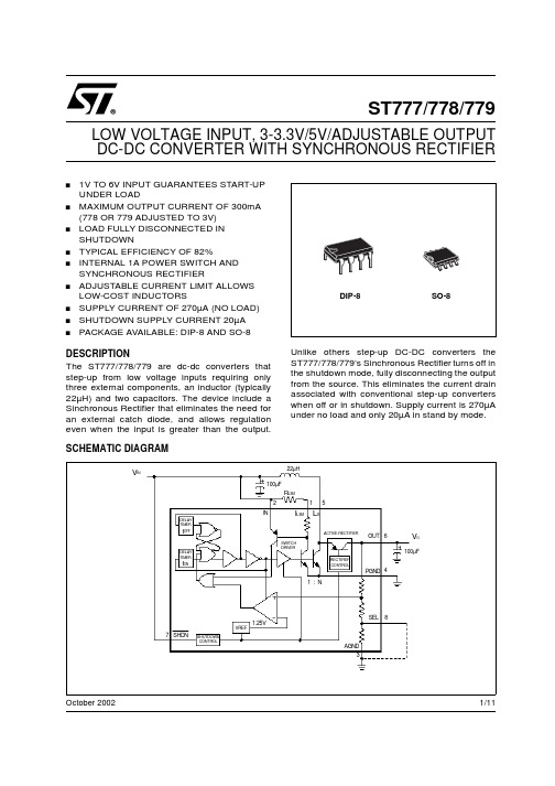
1/11October 2002s1V TO 6V INPUT GUARANTEES START-UP UNDER LOADsMAXIMUM OUTPUT CURRENT OF 300mA (778OR 779ADJUSTED TO 3V)sLOAD FULLY DISCONNECTED IN SHUTDOWNs TYPICAL EFFICIENCY OF 82%sINTERNAL 1A POWER SWITCH AND SYNCHRONOUS RECTIFIERsADJUSTABLE CURRENT LIMIT ALLOWS LOW-COST INDUCTORSs SUPPLY CURRENT OF 270µA (NO LOAD)s SHUTDOWN SUPPLY CURRENT 20µA sPACKAGE AVAILABLE:DIP-8AND SO-8DESCRIPTIONThe ST777/778/779are dc-dc converters that step-up from low voltage inputs requiring only three external components,an inductor (typically 22µH)and two capacitors.The device include a Sinchronous Rectifier that eliminates the need for an external catch diode,and allows regulation even when the input is greater than the output.Unlike others step-up DC-DC converters the ST777/778/779’s Sinchronous Rectifier turns off in the shutdown mode,fully disconnecting the output from the source.This eliminates the current drain associated with conventional step-up converters when off or in shutdown.Supply current is 270µA under no load and only 20µA in stand by mode.ST777/778/779LOW VOLTAGE INPUT,3-3.3V/5V/ADJUSTABLE OUTPUT DC-DC CONVERTER WITH SYNCHRONOUS RECTIFIERV INV O22µH100µF100µFR LIMI LIM L XINOUT PGND SEL AGND12345678SHDN1.25VVREFSHUTDOWN CONTROLDELAY TIMERDELAY TIMERt OFFt ONSWITCH DRIVERACTIVE RECTIFIERRECTIFIER CONTROL1:NSCHEMATIC DIAGRAMST777/778/7792/11ABSOLUTE MAXIMUM RATINGSAbsolute Maximum Ratings are those values beyond which damage to the device may occur.Functional operation under these condition is not implied.ORDERING CODESCONNECTION DIAGRAMPIN CONNECTIONSTHERMAL DATASymbol ParameterValue Unit V CCDC Input Voltage to GND -0.3to +7V LXSwitch off Pin Voltage -0.3to +7V Switch on Pin Voltage 30sec short to IN or OUTOUT,SHDN Output,Shutdown Voltage -0.3to +7V AGND to PGNDAnalog and Power Ground -0.3to +0.3V FBFB Pin Voltage-0.3to (OUT+0.3)V P TOT Continuous Power Dissipation (at T A =85°C)DIP-8550mW Continuous Power Dissipation (at T A =85°C)SO-8344T STG Storage Temperature Range-40to 150°C T OPOperating Ambient Temperature Range0to 85°CTYPE DIP-8SO-8ST777ST777ACN ST777ACD ST778ST778ACN ST778ACD ST779ST779ACNST779ACDPin No.SYMBOL NAME AND FUNCTION1ILIM Sets switch current limit input.Connect to IN for 1A current limit.A resistor from ILIM to IN sets lower peak inductor currents.2IN Input from battery3AGND Analog ground.Not internally connected to PGND.4PGND Power ground.Must be low impedance;solder directly to ground plane or star ground.Connect to AGND,close to the device.5LX Collector of 1A NPN power switch and emitter of Sinchronous Rectifier PNP .6OUT Voltage Output.Connect filter capacitor close to pin.7SHDNShutdown input disables power supply when low.Also disconnets load from input.Threshold is set at V IN /2.8SEL/N.C./FB -Selection pin for 3/3.3V version (778);-Not internally connected for 5V version (777);-Feedback pin for adjustable version (779).Symbol ParameterDIP-8SO-8Unit R thj-ambThermal Resistance Junction-ambient100160°C/WST777/778/7793/11ELECTRICAL CHARACTERISTICS (V IN =2.5V,C I =22µF,C O =100µF,SHDN and ILIM connected to IN,AGND connected to PGND,T A =0to 85°C,unless otherwise specified.Typical values are referred at T A =25°C)Note 1:Output in regulation,V OUT =V OUT (nominal)± 4%.Note 2:At hight V IN to V OUT differentials,the maximum load current is limited by the maximum allowable power dissipation in the package.Note 3:Start-up guaranteed under these load conditions.Note 4:Minimum value is production tested.Maximum value is guaranteed by design and is not production tested.Note 5:In the ST779supply current depends on the resistor divider used to set the output voltage.Note 6:V OUT is set to a target value of +5V by 0.1%external feedback resistors.V OUT is measured to be 5V±2.5%to guarantee the error comparator trip point.Symbol Parameter Test ConditionsMin.Typ.Max.Unit V START Start up Voltage I LOAD <10mA,T A =25°C (Note 1)1V V IN(MAX)Maximum Input Voltage (Note 1,2)6V V OOutput Voltage ST777779(set to 5V),(Note 3)I LOAD ≤ 30mA,V IN = 1.1V to 5V or I LOAD ≤ 80mA,V IN = 1.8V to 5V or I LOAD ≤ 130mA,V IN = 2.4V to 5V 4.85.05.2VOutput Voltage ST778(Note 3)SEL=0VI LOAD ≤ 50mA,V IN =1.1V to 3.3V or I LOAD ≤ 210mA,V IN =1.8V to 3.3V or I LOAD ≤ 300mA,V IN =2.4V to 3.3V 3.17 3.30 3.43VSEL=OPENI LOAD ≤ 30mA,V IN =1.1V to 3V or I LOAD ≤ 210mA,V IN =1.8V to 3V or I LOAD ≤ 300mA,V IN =2.4V to 3V2.883.00 3.12VOutput Voltage Range ST779(Note 4)2.76.5V I IN No Load Supply Current I LOAD =0mA,(Switch ON)(Note 5)270µAI SHDN Shutdown Supply Current SHDN=0V,(Switch OFF)2035µA I IN SHDNShutdown Input Current SHDN =0to V IN 15100nA SHDN =V IN to 5V 1240µA υEfficiencyI LOAD =100mA 82%V IH Shutdown Input Threshold V IN =1V to 6VV IN /2+0.25V I LIMCurrent Limit1.0A I LIM TEMPCO Current Limit TemperatureCoefficient-0.3%/°C t OFFMIN Minimum Switch Off Time 1.2µst ONMAXMaximum Switch ON TimeV IN =2.5V 4.5V IN =1.8V 6.5V IN =1V15V CESAT NPN Switch saturation VoltageI SW =400mA 0.25VI SW =600mA 0.33I SW =1000mA0.5V CESAT NPN Rectifier Forward DropI SW =400mA 0.18V I SW =600mA 0.22I SW =1000mA0.4V FB Error Comparator Trip Point ST779,over operating inputvoltage (Note 6)1.23±2%V I FB FB Pin Bias Current ST779,V FB =1.3V 50nA I LXSwitch Off Leakage Current 0.1µA Rectifier Off Leakage Current0.1µAST777/778/7794/11TYPICAL APPLICATION CIRCUITAPPLICATIONS INFORMATIONR1and R2must be placed only in ST779applications to set the output voltage according to the following equation:V OUT =(1.23)[(R1+R2)/R2]and to simplify the resistor selection:R1=R2[(V OUT /1.23)-1]It is possible to use a wide range of values for R2(10K Ωto 50K Ω)with no significant loss of accuracy thanks to the very low FB input current.To have 1%error,the current through R2must be at least 100times FB’s bias current.When large values are used for the feedback resistors (R1>50K Ω),stray output impedance at FB can incidentally add "lag"to the feedback response,destabilizing the regulator and creating a larger ripple at the output.Lead lengths and circuit board traces at the FB node should be kept pensate the loop by adding a "lead"compensation capacitor (C3,100pF to 1nF)in parallel with R1.The typical value of the L1inductor is 22µH,enough for most applications.However,are also suitable values ranging from 10µF to 47µF with a saturation rating equal to or greater than the peak switch -current limit.Efficiency will be reduced if the inductor works near its saturation limit,while will be maximized using an inductor with a low DC resistance,preferably under 0.2Ω.Connecting ILIM to V IN the maximum LX current limit (1A)is set.If this maximum value is not required is possible to reduce it connecting a resistor between ILIM and V IN (See Figure 16to choose the right value).The current limit value is misured when the switch current through the inductor begins to flatten and does’nt coincide with the max short circuit current.Even if the device is designed to tolerate a short circuit without any damage,it is strictly recommended to avoid a continuos and durable short circuit of the output to GND.To achieve the best performances from switching power supply topology,particular care to layout drawing is needed,in order to minimize EMI and obtain low noise.Moreover,jitter free operation ensures the full device functionality.Wire lengths must be minimized,filter and by-pass capacitors must be low ESR type,placed as close as possible to the integrated circuit.Solder AGND and PGND pins directly to a ground plane.ST777/778/7795/11TYPICAL CHARACTERISTICS (unless otherwise specified T j =25°C,C I =22µF,C O =100µF)Figure 1:Output Voltage vs TemperatureFigure 2:Output Voltage vs Temperature Figure 3:Efficiency vs Temperature Figure 4:Efficiency vs Input VoltageFigure 5:Efficiency vs Output CurrentFigure 6:Efficiency vs Low OutputCurrentST777/778/7796/11Figure 7:No Load Supply Current vs Input VoltageFigure 8:No Load Supply Current vs Temperature Figure 9:Shutdown Input Threshold vs Input VoltageFigure 10:Minimum Switch Off Time vs TemperatureFigure 11:Maximum Switch ON Time vs TemperatureFigure 12:FB Pin Bias Current vsTemperatureST777/778/7797/11Figure 13:Error Comparator Trip Point vs TemperatureFigure 14:Maximum Output Current vs Input Voltage Figure 15:Maximum Output Current vs Input VoltageFigure 16:Peak Inductor Current vs Current-LimitResistorST777/778/7798/11Figure 17:Line TransientFigure 18:Load Transient Figure 19:Switching WaveformFigure 20:Switching WaveformPRINTED DEMOBOARD (Not in scale)VoutVinVout (5V)IoutST777/779Vin=2.5VIout=10m A to 130m AVoutIswVin=1.1V Iout=30mAVoutIswVin=2.5VIout=30mA元器件交易网ST777/778/779 Information furnished is believed to be accurate and reliable. However, STMicroelectronics assumes no responsibility for theconsequences of use of such information nor for any infringement of patents or other rights of third parties which may result fromits use. No license is granted by implication or otherwise under any patent or patent rights of STMicroelectronics. Specificationsmentioned in this publication are subject to change without notice. This publication supersedes and replaces all informationpreviously supplied. STMicroelectronics products are not authorized for use as critical components in life support devices orsystems without express written approval of STMicroelectronics.© The ST logo is a registered trademark of STMicroelectronics© 2002 STMicroelectronics - Printed in Italy - All Rights ReservedSTMicroelectronics GROUP OF COMPANIESAustralia - Brazil - Canada - China - Finland - France - Germany - Hong Kong - India - Israel - Italy - Japan - Malaysia - Malta - MoroccoSingapore - Spain - Sweden - Switzerland - United Kingdom - United States.© 11/11。
LM7805中文资料
LM7805中文资料目录1.lm7805介绍2.实际应用3.引脚序号、引脚功能4.lm7805应用电路5.7805电参数三端稳压集成电路lm7805。
电子产品中,常见的三端稳压集成电路有正电压输出的lm78 ××系列和负电压输出的lm79××系列。
顾名思义,三端IC 是指这种稳压用的集成电路,只有三条引脚输出,分别是输入端、接地端和输出端。
它的样子象是普通的三极管,TO- 220 的标准封装,也有lm9013样子的TO-92封装。
1.lm7805介绍用lm78/lm79系列三端稳压IC来组成稳压电源所需的外围元件极少,电路内部还有过流、过热及调整管的保护电路,使用起来可靠、方便,而且价格便宜。
该系列集成稳压IC型号中的lm78或lm79后面的数字代表该三端集成稳压电路的输出电压,如lm7806表示输出电压为正6V,lm7909表示输出电压为负9V。
因为三端固定集成稳压电路的使用方便,电子制作中经常采用。
最大输出电流1.5A,LM78XX系列输出电压分别为5V;6V;8V;9V;10V;12V;15V;18V;24V。
2.实际应用在实际应用中,应在三端集成稳压电路上安装足够大的散热器(当然小功率7805IC内部电路图.的条件下不用)。
当稳压管温度过高时,稳压性能将变差,甚至损坏。
当制作中需要一个能输出1.5A以上电流的稳压电源,通常采用几块三端稳压电路并联起来,使其最大输出电流为N个1.5A,但应用时需注意:并联使用的集成稳压电路应采用同一厂家、同一批号的产品,以保证参数的一致。
另外在输出电流上留有一定的余量,以避免个别集成稳压电路失效时导致其他电路的连锁烧毁。
在lm78 ** 、lm79 ** 系列三端稳压器中最常应用的是TO-220 和TO-202 两种封装。
这两种封装的图形以及引脚序号、引脚功能如附图所示。
图中的引脚号标注方法是按照引脚电位从高到底的顺序标注的。
AD7787中文资料

AD7787: 低功耗、双通道、24位Σ-Δ型ADC
AD7787是一款适合低频测量应用的低功耗、完整模拟前端,内置一个低噪声24位Σ-Δ型ADC,该ADC
具有一个差分输入和一个可缓冲或无缓冲的单端输入。
该器件采用内部时钟工作,因此,用户不必为其提供时钟源。
AD7787的输出数据速率可通过软件编程设置,可在9.5 Hz至120 Hz的范围内变化,更新速率较低时均方根(RMS)噪声为1.1 µV。
内部时钟频率可以使用系数2、4或8进行分频,从而可以降低功耗。
更新速率、截止频率和建立时间与时钟频率成比例变化。
该器件采用2.5 V至5.25 V电源供电。
工作电压为3 V时,最大功耗为225 µW,采用10引脚MSOP封装。
特点和优势
∙电源:
- 工作电压:2.5 V至5.25 V
- 正常模式:最大75 µA
- 省电模式:最大1 µA
∙均方根(RMS)噪声:1.1 µV(9.5 Hz更新速率时)
∙19.5位峰-峰值分辨率(22位有效分辨率)
∙积分非线性:3.5 ppm(典型值)
∙50 Hz和60 Hz同时抑制
∙内部时钟振荡器
∙轨到轨输入缓冲
∙V DD监控通道
∙温度范围:–40°C~+105°C
∙10引脚MSOP封装
∙接口:
- 三线式串行接口
- SPI®、QSPI™、MICROWIRE™、DSP兼容
- SCLK上为施密特触发器。
低功耗24位模数转换器AD7787
低功耗 24 位模数转换器 AD7787 1 概述 7787 是公司推出的适用于低频测量的低功耗、低噪声、双通道、 24 位 Σ-Δ 模数转换器。
它利用片内时钟电路工作,因而无需用户提供时钟源。
7787 的数据输出速率可由软件设置,这一特性使其转换速率可在 95——120 之间变化。
该芯片采用 10 脚封装,非常适合用需要高分辨率、低功耗的便携式 仪器、温度测量、传感器测量、称重仪等。
7787 的主要特点如下 ●可在 25——525 电压范围内工作。
正常模式下的最大工作电流为 75μ,掉电模式下为 1μ; ●95 转换速率下的噪声为 11μ;范文先生网收集整理 ●22 位有效分辨率时的峰峰值分辨率为 195 位; ●内部非线性度 35; ●具有 50 和 60 同步抑制功能; ●具有内部时钟振荡器和监控通道; ●内含轨至轨输入缓冲器; ●带有三线制串行接口,与、、及兼容;●工作温度范围为-40——+105℃。
2 引脚排列及功能 7787 的引脚排列如图 1 所示。
3 工作原理 7787 的内部结构功能框图如图 2 所示。
它内部集成了一个 Σ-Δ 调制器、一个缓冲器和一个片内数字滤波器。
数字滤波器的主要功能是提供正常模式抑制。
在 166 默认转换速率条件下,它能提供 50 和 60 的同步抑制。
7787 采用内部时钟电路工作,因而无需外接时钟源。
时钟频率以 2、4、8 因子分频后应用于调制器和滤波器,从而可降低 芯片的功耗。
当采用 5 单电源供电、缓冲器使能且时钟以最大速率工作时,7787 的功耗电流最大仅为 160μ 7787 有 5 个片内寄存器通信寄存器、状态寄存器、模式寄存器、滤波 器寄存器和数据寄存器。
所有对 7787 的设置和控制都是通过这些寄存器来实现的。
7787 具有三种工作模式,分别为单转换模式、连续转换模式和连续模 式。
31 单转换模式 单转换模式时的转换时序如图 3 所示。
- 1、下载文档前请自行甄别文档内容的完整性,平台不提供额外的编辑、内容补充、找答案等附加服务。
- 2、"仅部分预览"的文档,不可在线预览部分如存在完整性等问题,可反馈申请退款(可完整预览的文档不适用该条件!)。
- 3、如文档侵犯您的权益,请联系客服反馈,我们会尽快为您处理(人工客服工作时间:9:00-18:30)。
MICROWAVE POWER GaAs FET
MICROWAVE SEMICONDUCTOR TIM7785-8SL
TECHNICAL DATA
FEATURES
LOW INTERMODULATION DISTORTION HIGH GAIN
IM3=-45 dBc at Pout= 28.5dBm G1dB=6.0dB at 7.7GHz to 8.5GHz Single Carrier Level BROAD BAND INTERNALLY MATCHED FET HIGH POWER
HERMETICALLY SEALED PACKAGE
P1dB=39.5dBm at 7.7GHz to 8.5GHz
RF PERFORMANCE SPECIFICATIONS ( Ta= 25°C )
CHARACTERISTICS SYMBOL CONDITIONS UNIT
MIN. TYP.MAX. Output Power at 1dB Gain Compression Point
P 1dB dBm 38.5 39.5⎯
G 1dB Power Gain at 1dB Gain Compression Point dB 5.0 6.0 ⎯ Drain Current I DS1 A
⎯
2.2 2.6 VDS= 10V f= 7.7 to 8.5GHz
ΔG Gain Flatness ⎯ ⎯
dB ±0.6ηadd ⎯ ⎯
30 Power Added Efficiency % 3rd Order Intermodulation Distortion IM3 dBc -42 -45 ⎯ Two-Tone Test Po=28.5dBm (Single Carrier Level) ⎯ A 2.2 2.6 Drain Current
IDS2 (VDS X IDS + Pin – P1dB)°C ⎯ ⎯
Channel Temperature Rise
ΔTch 80 X Rth(c-c)
Recommended Gate Resistance(Rg): 150 Ω (Max.)
ELECTRICAL CHARACTERISTICS ( Ta= 25°C )
CHARACTERISTICS SYMBOL CONDITIONS UNIT MIN. TYP.MAX.
gm V DS = 3V ⎯ ⎯
1800 Transconductance mS I DS = 3.0A
V GSoff V DS = 3V Pinch-off Voltage V -1.0 -2.5-4.0
I DS = 30mA
I DSS V DS = 3V ⎯ ⎯
Saturated Drain Current A 5.2 V GS = 0V
V GSO I GS = -100μA Gate-Source Breakdown Voltage V -5 ⎯ ⎯ R th(c-c) °C/W ⎯
Thermal Resistance Channel to Case 2.5 3.8
The information contained herein is presented only as a guide for the applications of our products. No responsibility is assumed by TOSHIBA for any infringements of patents or other rights of the third parties which may results from its use, No license is granted by implication or otherwise under any patent or patent rights of TOSHIBA or others.
The information contained herein is subject to change without prior notice. It is therefor advisable to contact TOSHIBA before proceeding with design of equipment incorporating this product.
ABSOLUTE MAXIMUM RATINGS ( Ta= 25°C )
UNIT
RATING CHARACTERISTICS SYMBOL
Drain-Source Voltage V 15
V DS
Gate-Source Voltage V -5
V GS
I DS
Drain Current A 7.0 Total Power Dissipation (Tc= 25 °C) W 39.5
P T
Channel Temperature 175
T ch°C
Storage Temperature
T stg°C -65 to +175 PACKAGE OUTLINE (2-11D1B)
Unit in mm
(1) Gate
(2) Source
(3) Drain
HANDLING PRECAUTIONS FOR PACKAGE MODEL
Soldering iron should be grounded and the operating time should not exceed 10 seconds
at 260°C.
RF PERFORMANCE
Output Power (Pout) vs. Frequency
40 P o u t (d B m )
39 38 37
7.7
7.9
8.1
8.3
8.5
Frequency (GHz)
Output Power(Pout) vs. Input Power(Pin)
Pout
ηadd 42
41 40 39
38 37 36 35 34 33
P o u t (d B m )
80 70 60 50 40 30 20
10
ηa d d (%)
27 29 31 33 35 37
Pin(dBm)
Power Dissipation vs. Case Temperature
40
30
20 10
0 40 80 120 160 200 Tc (°C)
P T (W )
IM3 vs. Output Power Characteristics
-10
-20 f=5MHz
-30 I M 3 (d B c )
-40 -50 -60 24
26
28 30 32 34 Pout (dBm) @Single carrier level。
