SM-1851产品结构说明书
SM100-M系列HART数据采集器产品说明书(2018_07_05)
2、SM100-M 系列 HART 数据采集器硬件说明
2.1 实物图
2.2 接线图
2.3 端口介绍
端口名称 功能/接入设备
NET 网关
RS485D- RS485D+ RS232TX RS232RX GND
RS485 通讯
RS232 通讯
GND
POW
直流电源
端口名称
LOOP1+ LOOP1- LOOP2+ LOOP2- LOOP3+ LOOP3- LOOP4+ LOOP4-
HART 仪表 16
● NET:以太网接口。 ● RS485D-、R485D+:RS485 通讯,485 线正负端分别接到 RS485+、RS485-端口。 ● RS232TX、RS232RX、GND:RS232 通讯,参照连接图连接仪器设备,实现采集器与设备之间的数据
传输。 ● GND、POW:电源接口接线端子,POW 接电源正极,GND 接电源负极。 ● LOOP1+、LOOP1-~LOOP16+、LOOP16-:共16组HART仪表通讯接口接线端子。
1、SM100-M 系列 HART 数据采集器介绍
1.1 产品简介
SM100-M系列HART数据采集器是采用ARM微处理器、HART协议调制解调专用芯片并结合大量的实 践经验所研发的产品。其按照工业产品要求进行设计,具有很高的可靠性及稳定性。数据采集器配 有标准的RS485接口、RS232接口和网关,能与有HART协议的智能仪表进行数据透明传输或者转换为 MODBUS_RTU或MODBUS_TCP协议读取数据,保证数据进行实时传输。
2、SM100-M 系列 HART 数据采集器硬件说明........................................................................................... - 2 2.1 实物图............................................................................................................................................ - 2 2.2 接线图............................................................................................................................................ - 2 2.3 端口介绍........................................................................................................................................ - 3 2.4 指示灯及拨码开关说明................................................................................................................ - 3 -
M-15S-说明书

──
96.80
MBE058F03
当按住 F 键不放,为快速后退 目标值:右边会显示─ ─ 现在值:会快速减少数值 ※注:按 8 或 9 键为
前进/后退慢速(依机器性能而定)
3
单动模式
功能说明:在单动模式下可执行自动定位。 例 如:目前 M15 现在值显示 100.00mm,要到达目标值 200.00mm,设定步骤如下:
控制器规格
1、外观尺寸:115w × 115h × 73d (mm) 2、开孔尺寸:93w × 108h (mm) 3、安装孔位:M3 × 4 104 × 104 (mm) 4、供应电压:24 VDC 50mA 2 号 1.5V 电池 × 1 5、电池电压控制:有低电压警示 6、读头讯号线:标准:3m 7、热膨胀系数:α = 16 × 10-6 × 1/K 8、读头间隔:max. 2.5mm 9、显示屏幕:15mm LED × 6 digits × 2 line 10、输出:4 digital output(AC250V / 7A;DC24V/10A) 11、输入:4 digital input(24VDC) 12、操作组件:20 个按键 13、Test mark/interfer.Protection class:3 accord. to IEC 801 14、速度:1.5m/s 15、系统精度:± (0.025+0.02L)mm (L: 米) 16、重现性:0.01mm 17、温度:工作温度 0 + 50℃;储存温度 –20 +70℃ 18、湿度:max. 95% rF(Condensation not permitted)
表示 LED 灯亮闪烁
重力传感器产品说明书
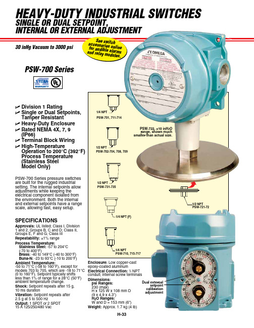
HEAVY-DUTY INDUSTRIAL SWITCHESSINgLE oR DUAL SETPoINT,PSW-700 SeriesDual external setpoint calibrationadjustment PSW-700 Series pressure switches are built for the rugged industrial setting. The internal setpoints allow adjustments while keeping the electrical component isolated from the environment. Both the internal and external setpoints have a range scale, allowing fast, easy setup.PSW-722, ±10 inH 2O range, shown much smaller than actual size.U Division 1 RatingU Single or Dual Setpoints, Tamper ResistantU Heavy-Duty Enclosure U Rated NEMA 4X, 7, 9 (IP66)U Terminal Block Wiring U High-TemperatureOperation to 200°C (392°F) Process Temperature (Stainless Steel Model Only)PSW-710, 715-7171/4 NPT1/4 NPT (F)PSW-731-7351/2 NPTPSW-702-704, 708, 709SPECIFICATIONSApprovals: UL listed; Class I, Division 1 and 2, Groups B, C and D; Class II, Groups E, F and G; Class III Repeatability: ±1% range Process Temperature:Stainless Steel: -57 to 204°C (-70 to 400°F)Brass: -40 to 149°C (-40 to 300°F) Buna-N: -23 to 93°C (-10 to 200°F)Ambient Temperature:-50 to 71°C (-58 to 160°F), except for models 703 to 705, which are -18 to 71°C (0 to 160°F). Setpoint typically shifts less than 1% of range for a 28°C (50°F) ambient temperature change.Shock: Setpoint repeats after 15 g, 10 ms durationVibration: Setpoint repeats after 2.5 g at 5 to 500 HzOutput: 1 SPDT or 2 SPDT 15 A 125/250/480 VacEnclosure: Low copper-cast epoxy-coated aluminumElectrical Connection: 3⁄4 NPT conduit; internal screw terminals Dimensions:psi Ranges:230 (max) H x 125 W x 108 mm D (9 x 4.9 x 4.3") H 2O Ranges:W and D = 153 mm (6") Weight: Approx. 1.7 kg (4 lb)PSW-721-72INDUSTRIAL SWITCHES PSW-707, 0 to 500 psirange, shown smallerthan actual size。
Mitsubishi Electric 工业机器人 MELFA RV-8CRL 产品介绍说明书

FACTORY AUTOMATIONMITSUBISHI ELECTRICINDUSTRIAL ROBOTMELFA RV-8CRLAllied Automation 800-214-0322Pursuing practical performanceUses an HK motor, the latest servomotor from Mitsubishi Electric. This allows improved torque characteristics, accuracy, and responsiveness while substantially reducing the size and weight. This adds up to much better robot performance and greater compactness.Continuous operation performanceLighter weight and improved heat release translate to improved continuous operation performance.Beltless coaxial drive mechanismA coaxial drive mechanism without belts is used for transmission to each axis (excluding the J4 and J5 axes).Simplification of the structure has improved transmission efficiency and reliability while also improving the ease of maintenance.No backup batteryThe use of the new HK motor eliminates the need for a battery to back up the robot’s internal encoder.This eliminates the cost and effort of regularreplacement as well as the risk of losing origin coordinates due to battery failure.A signal wire and air piping that can be used for gripper control, etc., are built in from the base to the forearm. Both ends of the signal wire haveuniversal D-sub connectors for use in various applications.Highest-in-class load capacityFeaturing a highest-in-class maximum load capacity of 8 kg, these robots boast a lighter-weight structure and reduced unit weight thanks to their simplified drive system and optimized arm structure, resulting in enhanced load capacity.Largest-in-class effective working areaOffers highest-in-class maximum reach radius of 931 mm. The use of a no-offset lower arm structure eliminating the J2-axis joint offset minimizes the interference region in the minimum turning radius and provides the largest-in-class effective working area.Standard IP65 supportComes standard with environmental resistance features allowing installation in plants and equipment where dust or oil mist is present.Can be used in oil mist environmentsJ6-axis motorJ3-axismotor J2-axismotorJ1-axismotor Slim & Compact Robot Offering a High Level of Utility and DesignSlim & compactA smooth, curved design complements the slim arm and compact joints. The external design is marked by minimalist, functional design.*Installation pitch:□160 mm (same as RV-4FR and 20% less than RV-7FR)Protrusionless structureIn addition to a slim, compact exterior and small robot base, its structure features minimal protrusions to the front, back, and sides, resulting in reduced interference with surroundings when the robot operates. This makes it suited to integration with automation cells and manufacturing equipment.1High-performance Controller Makes MELFA More IntelligentSafety monitoring functionWe will prepare a safety function compliant with international standards that simplifies risk assessments.Safety I/OExtends redundant safety I/O to 8 inputs and 4 outputs. Enablesdevelopment of various safety systems.Safety logic editingSimplifies development and operation of safety systems with safety logic editing.●Program editing and debugging ●Simulation function ●3D viewer●Monitoring function●Melfa RXM.ocx communication middlewareTrackingRobot tracks workpiece on conveyor, allowing transfer, alignment, and assembly without stopping conveyor.Additional axis controlBuild user mechanism controlling additional axes simultaneously with robot such as robot drive axis or turntable or separate from robot such as loader or positioning device. Control up to 8 axes. Our MELSERVO (MR-J4-B)servomotor can be used with additional axes.Robot mechanism thermal compensation functionMeasures the temperature of the robot arm and automatically corrects errors arising from thermal expansion of the arm.Callibration assistance functionAutomated calibration translates to simplification of installation of two-dimensional vision sensor and improvement of operational accuracy.Coordinated control of additional axesLinks robot and travel base for high-accuracy processing and assembly at specific speed.Also supports optional MELFA SmartPlusfunctional enhancement *1Comes standard with tracking and additional axis control PC software supporting everything from robot system designto installation, debugging, operation, and maintenance●Vision sensor configuration tool allows easy calibration of robot and camera ●Easy connection of robot and camera via Ethernet ●Easy control via robot program vision control commandSimultaneous controlmechanismsMechanism 1Mechanism 2Mechanism 3Up to 3Additional axesVision sensorSupports multiple conveyors simultaneously (up to 8)*1: Coming soonRobot controllerRobotLaser scannerTeaching boxRT ToolBox3Emergency stopArea sensorLamp2SpecificationsMechanical interfaceInternal wiring/pipingWiring/pipingInstallation dimensionsExternal dimensions/operating rangeMain Specifications15-pin D-sub AWG#24 (0.2mm ) ×15φ6 air joint (2)φ6 hose (2)Black Green Red Brown Yellow OrangeBlue Purple Gray Pink Light blue (Black)/Yellow (Black)/White (Black)/Blue 123456789101112131415123456789101112131415①②Baseφ6 air joint ①Tool wiring connector (15-pin D-sub)Tool wiring connector (15-pin D-sub)φ6 air joint ②Air pipe (2)φ6 air joint ①BaseUpper armForearmView A15-pin D-subForearmφ6 air joint ②Tool wiring (15)Tool wiring connectorRz25R z 25(Installation reference plane)(I n s t a l l a t i o n r e f e r e n c e p l a n e )1908080(160)978080(160)9797φ40h 8φ20H 7D6P .C.D .φ31.545°4-M5 thread depth 8φ5H7D84-φ9 installation hole*1: The wall mounting specifications are special specifications that restrict the operating range of the J1 axis.*2: “Maximum load capacity” is the maximum weight that can be loaded under the limitation of a mechanical interface having a downward attitude (within ±10° of the vertical position).View BP point operating areaP pointR 930.5-170°+170°R 219.315071R 150930.5930.51320.5244.4634.4930.585470390450100R 930.5+110°-110°Control point (R point)P point operating areaP point Downward limit of wristR 219.3102028020A71BWrist's downward singularity boundarySpace for the cable connectionMinimum: 310250256White 3External dimensions*2: Power supply voltage variability is within 10%.*3: Power capacity is recommended value.Note that power capacity does not include making current when turning on. Power capacity is an estimate.*4: Grounding work is to be performed by the customer.*5: Recommended USB cable (USB Type A, USB Mini-B Type): MR-J3USBCBL3M (Mitsubishi Electric), GT09-C30USB-5P (Mitsubishi Electric System & Service)*6: Mode select switch is to be provided by the customer.Controller specificationsStand-alone robot controllerRobot controller can be used for centralized control.430(30)30(3.5)37099.59642534045(40)(45)CR800-D4System configurationParallelinput-output interfaceinput-output unitExternal input-output cableCC-Link <Standard devices>GOT Pulse encoderServo Network R56TBR32TBsupport(SmartPlus)Machine cableController protection box<Functional options>Force sensor set MELFA-3D Vision⑨⑥RT ToolBox3 mini RT ToolBox3RT ToolBox3 Pro⑭②Encoder interfaceRobotRobot controller*1: Coming soon5OptionsController optionsFunctional optionsExpanded software functions*1: Coming soon6L (NA )09102ENG-BAll trademarks acknowledged.Printed December 2019HEAD OFFICE: TOKYO BLDG., 2-7-3 MARUNOUCHI,CHIYODA-KU, TOKYO 100-8310, JAPANMitsubishi Electric Corporation Nagoya Works is a factory certified for ISO 14001 (standards for environmental management systems) and ISO 9001(standards forquality assurance management systems)Global Partner. Local Friend.Allied Automation 800-214-0322。
微尔赛米集团2013年产品说明书
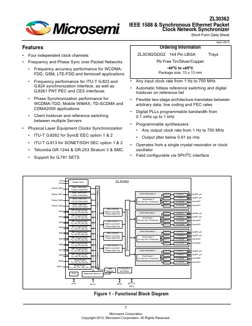
1Features•Four independent clock channels•Frequency and Phase Sync over Packet Networks •Frequency accuracy performance for WCDMA-FDD, GSM, LTE-FDD and femtocell applications •Frequency performance for ITU-T G.823 and G.824 synchronization interface, as well as G.8261 PNT PEC and CES interfaces•Phase Synchronization performance forWCDMA-TDD, Mobile WiMAX, TD-SCDMA and CDMA2000 applications•Client holdover and reference switching between multiple Servers•Physical Layer Equipment Clocks Synchronization •ITU-T G.8262 for SyncE EEC option 1 & 2•ITU-T G.813 for SONET/SDH SEC option 1 & 2•Telcordia GR-1244 & GR-253 Stratum 3 & SMC •Support for G.781 SETS•Any input clock rate from 1Hz to 750MHz •Automatic hitless reference switching and digital holdover on reference fail•Flexible two-stage architecture translates between arbitrary data, line coding and FEC rates •Digital PLLs programmable bandwidth from 0.1mHz up to 1kHz•Programmable synthesizers•Any output clock rate from 1 Hz to 750 MHz •Output jitter below 0.61 ps rms•Operates from a single crystal resonator or clock oscillator•Field configurable via SPI/I 2C interfaceApril 2013Figure 1 - Functional Block DiagramZL30362IEEE 1588 & Synchronous Ethernet PacketClock Network SynchronizerShort Form Data SheetOrdering InformationZL30362GDG2144 Pin LBGATraysPb Free Tin/Silver/Copper-40o C to +85o CPackage size: 13 x 13 mmDetailed FeaturesGeneral•Four independent clock channels•Operates from a single crystal resonator or clock oscillator•Configurable its SPI/I2C interfaceTime Synchronization Algorithm•External algorithm controls software digital PLL to adjust frequency & phase alignment•Frequency, Phase and Time Synchronization over IP, MPLS and Ethernet Packet Networks•Frequency accuracy performance for WCDMA-FDD, GSM, LTE-FDD and femtocell applications, with target performance less than ± 15 ppb.•Frequency performance for ITU-T G.823 and G.824 synchronization interface, as well as G.8261 PNT EEC, PNT PEC and CES interface specifications.•Phase Synchronization performance for WCDMA-TDD, Mobile WiMAX, TD-SCDMA and CDMA2000 applications with target performance less than ± 1 s phase alignment.•Time Synchronization for UTC-traceability and GPS replacement.•Client reference switching between multiple Servers•Client holdover when Server packet connectivity is lostElectrical Clock Inputs•Nine input references configurable as single ended or differential and two single ended input references •Synchronize to any clock rate from 1 Hz to 750 MHz on differential inputs•Synchronize to any clock rate from 1 Hz to 177.75 MHz on singled-ended inputs•Any input reference can be fed with sync (frame pulse) or clock.•Synchronize to sync pulse and sync pulse/clock pair.•Flexible input reference monitoring automatically disqualifies references based on frequency and phase irregularities•LOS•Single cycle monitor•Precise frequency monitor•Coarse frequency monitor•Guard soak timer•Per input clock delay compensationElectrical Clock Engine•Digital PLLs filter jitter from 0.1 mHz up to 1 kHz•Flexible two-stage architecture translates between arbitrary data rates, line coding rates and FEC rates •Internal state machine automatically controls mode of operation (free-run, locked, holdover)•Automatic hitless reference switching and digital holdover on reference fail•Physical-to-physical reference switching•Physical-to-packet reference switching•Packet-to-physical reference switching•Packet-to-packet reference switching•Support for wide variety of Equipment Clock specifications•SyncE•ITU-T G.8262 option 1 EEC (Europe/China)•ITU-T G.8262 option 2 (USA)•SONET/SDH•ITU-T G.813 option 1 SEC (Europe/China)•ITU-T G.813 option 2 (USA)•ANSI T1.105/Telcordia GR-253 Stratum 3 for SONET•Telcordia GR-253 SMC•PDH•ITU-T G.812 Type I SSU•ITU-T G.812 Type III, ANSI T1.101/Telcordia GR-1244 Stratum 3E, including phase build out•ANSI T1.101/Telcordia GR-1244 Stratum 3•ANSI T1.101/Telcordia GR-1244 Stratum 4E/4•Selectable phase slope limiting•Holdover better than 1 ppb (when using < 0.1 Hz filter)•Supports ITU-T G.823, G.824 and G.8261 for 2048kbit/s and 1544kbit/s interfaces•Supports G.781 SETSElectrical Clock Generation•Four programmable synthesizers•Eight LVPECL outputs•Two LVPECL outputs per synthesizer•Generate any clock rate from 1 Hz to 750 MHz•Maximum jitter below 0.61 ps RMS•Meets OC-192, STM-64, 1 GbE & 10 GbE interface jitter requirements•Eight LVCMOS outputs•Two LVCMOS outputs per synthesizer•Generate any clock rate from 1 Hz to 177.75 MHz•Maximum jitter below 1 ps rms•Programmable output advancement/delay to accommodate trace delays or compensate for system routing paths•Outputs may be disabled to save powerAPI Software•Interfaces to 1588-capable PHY and switches with integrated timestamping•Abstraction layer for independence from OS and CPU, from embedded SoC to home-grown•Fits into centralized, highly integrated pizza box architectures as well as distributed architectures with multiple line cards and timing cardsApplications•ITU-T G.8262 System Timing Cards which support 1GbE and 10GbE interfaces•Telcordia GR-253 Carrier Grade SONET/SDH Stratum 3 System Timing Cards•System Timing Cards which supports ITU-T G.781 SETS (SDH Equipment Timing Source)•Integrated basestation reference clock for air interface for GSM, WCDMA, LTE and WiMAX macro, micro or femtocells•Mobile Backhaul NID, edge router or access aggregation node•EPON/GE-PON & GPON OLT•EPON/GE-PON & GPON ONU/OLT•DSLAM and RT-DSLAM•10Gigabit line cards•Synchronous Ethernet, 10GBASE-R and 10GBASE-W•SONET/SDH, Fibre Channel, XAUIInformation relating to products and services furnished herein by Microsemi Corporation or its subsidiaries (collectively “Microsemi”) is believed to be reliable. However, Microsemi assumes no liability for errors that may appear in this publication, or for liability otherwise arising from the application or use of any suchinformation, product or service or for any infringement of patents or other intellectual property rights owned by third parties which may result from such application or use. Neither the supply of such information or purchase of product or service conveys any license, either express or implied, under patents or other intellectual property rights owned by Microsemi or licensed from third parties by Microsemi, whatsoever. Purchasers of products are also hereby notified that the use of product in certain ways or in combination with Microsemi, or non-Microsemi furnished goods or services may infringe patents or other intellectual property rights owned by Microsemi.This publication is issued to provide information only and (unless agreed by Microsemi in writing) may not be used, applied or reproduced for any purpose nor form part of any order or contract nor to be regarded as a representation relating to the products or services concerned. The products, their specifications, services and other information appearing in this publication are subject to change by Microsemi without notice. No warranty or guarantee express or implied is made regarding the capability, performance or suitability of any product or service. Information concerning possible methods of use is provided as a guide only and does not constitute any guarantee that such methods of use will be satisfactory in a specific piece of equipment. It is the user’s responsibility to fully determine the performance and suitability of any equipment using such information and to ensure that any publication or data used is up to date and has not been superseded.Manufacturing does not necessarily include testing of all functions or parameters. These products are not suitable for use in any medical and other products whose failure to perform may result in significant injury or death to the user. All products and materials are sold and services provided subject to Microsemi’s conditions of sale which are available on request.Purchase of Microsemi’s I 2C components conveys a license under the Philips I 2C Patent rights to use these components in an I 2C System, provided that the system conforms to the I 2C Standard Specification as defined by Philips.Microsemi, ZL, and combinations thereof, VoiceEdge, VoicePort, SLAC, ISLIC, ISLAC and VoicePath are trademarks of Microsemi Corporation.TECHNICAL DOCUMENTATION - NOT FOR RESALEFor more information about all Microsemi productsvisit our Web Site at/timing-and-synchronization。
Sherline Jr. CNC Mill系列商品说明书
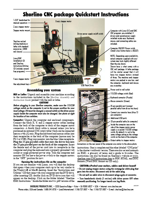
Z-axis stepper motor Y-axis stepper motor X-axis stepper motorA-axis plugDriver power supply on/off switchLinux/EMC Installation CD and SherlineInstructions/UtilitiesCD (includes severalfree programs)Sherline CNC package Quickstart InstructionsSherline vertical milling machine or lathe with standard accessories. (2000 mill shown)Computer with Linux O/S and EMC CNC program pre-installed, 4 drivers and second power supply installed inside case. Keyboard, mouse, and connecting cables are included.Additional USB portsKeyboard connector (Purple)Mouse connector (Green)25-pin parallel port (connectparallel cable from driver box here)Power cord to wall outlet Connect your monitor here (blue 15 pin connector)Connections on the rear panel of the computer are similar to the above photo.SHERLINE PRODUCTS INC. • 3235 Executive Ridge • Vista • CA 92081-8527 • USA • Internet: Phone orders, USA and Canada: 1-800-541-0735 • Local/International: 1-760-727-5857 • Fax: 1-760-727-5857 • E-mail:*********************4/11/13Output cables to stepper motors1-5/8” handwheel for manual operation Stepper motor mountHex adjustment keys115/230 voltage switch (Red)Inside the computer case on the side of the stepper motor power supply is a second 115/230 voltage switch. By default it is set to the same voltage setting as the voltage switch on the back of the computer.Assembling your systemMill or Lathe: Unpack and assemble your machine according to the instructions included in the Sherline Assembly and Instruction Guide packed with the mill or lathe.CAUTION!Before plugging in your Sherline computer, make sure the 115/230 voltage switch on the computer is set to the proper position for your local voltage. If it must be changed, a second switch on the driver power supply inside the computer must also be changed. See photo at right for location of two switches.Computer: Unpack the computer and enclosed components. Connect the black X, Y , and Z stepper motor cables leading from the back of the computer to each of the stepper motor connectors. A fourth black cable is unused unless you have purchased an optional CNC rotary table which can be connected here as a 4th (A) axis. Plug the keyboard and mouse cables into their receptacles at the back of the computer (mouse may be PS/2 or USB). Plug your monitor into the blue video receptacle. Plug the 25-pin parallel cable that exits the driver box into the 25-pin parallel port on the back of the computer. Insert the female end of the power cord into its receptacle in the computer and plug the male end into a properly grounded wall socket or surge protected power strip. Turn the computer and monitor ON but leave the power switch to the stepper motors in the “OFF” position for now.Opening the instructions file on the computerIf you are not familiar with Linux, you will find the desktop that opens when your computer starts up to be very similar to the Windows® or Mac® desktop. Insert the “Instructions and Utilities” CD that came with your computer into the DVD drive. After inserting CD, double click on DVD drive icon that will appear on the desktop. Click on the folder labeled “Sherline EMC Instructions.” Inside the folder are two .pdf versions of theinstructions. One is complete and the other labeled “CNCprint” is the shorter workbook version. There are also several manuals on EMC, a glossary of terms and a guide to G-codes. The instructions can also be found on Sherline’s website at /CNCinstructions.htm in PDF, HTML, and DOC formats (Word DOC format on CD only).CAUTION—Protect your motors, cables and driver board!• Do not unplug stepper motors using the rectangular white plug that goes into the motor. Disconnect only at the cable plug.• Do not pull on cable wires to disconnect plug —grip at connector.• Turn handwheels slowly (1 rev/sec) with driver power OFF when manually positioning. For longer travels use Jog Mode.USB Flash Drive25-pin parallel cable (to computer)NOTE: Depending upon availability, actual computer supplied with your system may look slightly different than the one shown.Shown here is what comes with a CNC mill package. A lathe package will be similar except that it will have two stepper motors instead of three. The machine and stepper motors are packed in one box, and the computer, keyboard and mouse are in puter ON/OFF Power switch (Small silver button below is RESET)Sherline CNC System SetupPlease read all of the instructions before attempting to use the EMC2 program. Machining with CNC is a complicated process, and you will be directed at the appropriate times to run the various features of the program once you have gained the knowledge you need to do so.Booting upBefore turning on your computer, make sure the 115/230 voltage switch on the computer is set to the proper voltage. If it must be changed, a second switch inside the computer must also be changed. Also make sure the ON/OFF switch for the stepper motor power supply is in the “OFF” (down) position. Once the EMC2 program is running, power to the stepper motors may be turned on.Opening the EMC Program–Login and Password When starting up, the computer will boot up without asking you to log in. If you log out of the desktop and log back in and get a login screen, enter sherline for the login (in lowercase letters) and sherline for the password. After completing the login, double click the [Go] button with your mouse, and the desktop will appear. To open EMC2, click on the lathe or mill, inch or metric icon for your machine on the desktop. If the icons don’t appear there, go to the top menu bar and navigate to Applications>CNC>EMC2. From that menu tree, choose either the inch or metric version for your machine and double click on it. This will open the “Axis GUI” version of EMC. Although this is slightly different version than the “Mini GUI” opened from the desktop icons you can still use it. Differences are explained in the EMC2 manual at Applications>CNC .Instruction filesThe instructions for use of your CNC system are pre-loaded on the Instructions and Utilities CD that came with your system. They are in .DOC (MS Word), PDF (Acrobat Viewer), and HTML formats. DOC files can be viewed on Windows® machines using MS Word or Wordpad. It will also open in OpenOffice on your Linux machine. HTML and PDF documents can be viewed on Windows, Mac® or Linux operating systems.Shutting down the computer when doneTo properly shut down your computer you should first exit all running programs. Then go to the menu bar at the top of the screen and navigate to System>Quit . After clicking on Quit , you have the choice to Log Off and leave the computer running or Turn off Computer which will log you off and shut down the computer. There is also a red power button icon in the upper right corner of the screen that will offer you several shut-down options. Finally, press and hold the power button on the front of the computer to turn off power to the computer.Emergency stopsIf you see a physical “crash” is about to occur, the fastest way to stop the stepper motors is to turn the driver board power switch on the side of the computer to OFF . The machine will have to be re-homed and the program restarted, but turning off power to the stepper motors while they are running will not cause damage. Running a slide until it hits a hard stop should not cause any physicalVersion 6.00 or higher (Ubuntu Linux)damage. Stop the motor as soon as possible by halting the program or by turning the stepper motor power supply switch to OFF to prevent possible overheating of the stalled motor.Transferring G-code files from another computer 1. Save your g-code text file to an appropriate media (DVD, CD, USB drive, etc.) in Plain Text (TXT) file format. Program files created in EMC will automatically be saved with the NGC extension. Either can be read by EMC. In other programs, limit your file name to eight characters or less in order to be able to transfer it to EMC.2. Insert the media containing your file into the appropriate drive or port on your Sherline Linux computer.3. On the desktop, click on the icon where your source file is located (DVD, USB, etc.) to open a window showing the contents of that media.4. On the desktop, double click the folder named G-Code .5. Drag the file from the selected media window and drop it into the G-Code folder window.Opening the file in EMC1. Open EMC2. Click the [AUTO] button along upper menu bar3. Click the [OPEN] button on lower menu bar4. Highlight the file by single clicking on it5. Click the [OPEN] buttonGetting answers to your questionsPlease read the instructions all the way through before calling Sherline with questions. Answers to questions relating to Linux or EMC can be found at . (Follow the links to the mailing list.) Using a Google search to ask a specific question often yields good results as well. Refer to the Sherline Assembly and Instruction Guide booklet that came with your machine for instructions on assembly, setup, adjustment and maintenance of your machine. If you have questions about assembly, missing or broken parts or other items relating to the machine, please call Sherline during business hours (M-F 8-5, Pacific) at 1-800-541-0735(USA)*****************************.From outside the USA call 1-760-727-5857.Minimum computer specifications for installation Successful installation of Linux/EMC2 v6.xx on your own computer requires at least the following:· Pentium III class processor or equivalent (800 MHz or faster)· 512 MB RAM (Sherline uses 1 Gb)· 20 GB hard drive or larger· CD/DVD drive (verify “Boot from DVD” is enabled before “Boot from HD” in the BIOS setting)· 25-pin parallel port to connect external driver boxNOTE: Sherline does not guarantee that the Linux operating system provided on the DVD enclosed with your CNC system or with the 8760 driver box will install on a non-Sherline computer. Sherline does not provide technical support for installation of Linux or EMC, but help is available on-line through the Linux group at or get subscription information on joining ****************************************************.For installations on another computer see /cgi-bin/wiki.pl?Hardware_Requirements for the latest requirements as specified by . Laptop computers are not recommended for CNC use.。
Minebea Intec Vessel and Silo Weighing产品说明书

Presented ByFt WorthDallas HoustonAustin800.225.8181Contact UsNicol Scales & Measurement is an ISO Accredited Calibration Company that has provided calibration, repair and sales of all types of weighing and measurement products since 1931.indicators as well as batch and system controllers.for measuring contentBuilding materials MachineryOur weighing electronics can be configured, operated and monitored remotely via an Ethernet connection‘Load cells and electronics from Minebea Intec are THE solution for turning a vessel or a silo into a scale.’Why Minebea IntecMinebea Intec products and solutions stand for quality and leading technology. Our process vessel and silo scales have proven themselves thousands of times around the globe – even under the toughest conditions. Throughout the entire life cycle, we also offer services that support our customers on site, from engineering support to user training. In this way, they always get the right solution for their requirements.// 6 Vessel and Silo Weighing Load cell PR 6202We offer a wide range of solutions for weighing vessels and tanks, both for storage and batching applications. This includes, at the one end of the spectrum, cost-effective solutions for inventory control where a weighing system accuracy of a few per cent is fully sufficient. At the other end, our customers find high accuracy solutions that allow them to very precisely dose a small component into a large batching vessel. This can even be done while a mixer is turning or the vessel is being heated.Load cellsThe core element of every process vessel scale is the load cell. Minebea Intec has decades of experience in designing and producing a wide range of load cells for different applications. All of our load cells feature:‘German quality’ ensuring superior accuracy and reliabilityRobustness, allowing overload capacities of up to 500 %Optimum IP protection guaranteeing a long lifetime even under harsh conditions. Minebea Intec load cells can even be immersed in water with a depth of 1.5 meters for 10,000 hoursWide operating temperature range of up to -30 ˚C to +95 ˚C making them suitable for virtually all weighing applications and production conditions. Our load cell PR 6212 even features an operating temperature range of up to +180 ˚CLoad cell PR 6212Load cell PR 6211Load cell PR 6201// 8 Vessel and Silo WeighingBeam type load cell MP 77Stainless steel bending beamLoad cell capacity range from 10 kg to 500 kgAccuracy class: 0.02 %Corresponding mounting kit: MP 97Load cell MP 77S-type compression load cell PR 6241Ultra-high precision load cell for batching applicationsLoad cell capacity range from 100 kg to 5 tAccuracy class: 0.04 % - 0.008 %Corresponding mounting kits: PR 6043 Mini FlexLock, PR 6041without constrainer, PR 6044 with additional functions and constrainerWägezelle PR 6241S-type tension load cell PR 6246Ultra-high precision load cell for batching applicationsLoad cell capacity range from 100 kg to 3 tAccuracy class: 0.04 % - 0.008 %Corresponding mounting kit: PR 6046Load cell PR 6246S-type tension load cell MP 76For suspended process scalesLoad cell capacity range from 60 kg to 5 tAccuracy class: 0.03 % - 0.025 %Corresponding mounting kit: MP 96Load cell MP 76Load cell PR 6251Load cell MP 58Load cell MP 79OPCWeight transmitter Weight transmitter PR 5230The weight transmitter PR 5230 offers the same specification as the PR 5220, with Multiple options allow the customer individual configuration of the transmitter Includes EasyFill ®Includes EasyFill ®Weight indicator X3Including EasyFill ®Weight controller Maxxis 4 Weight controller Maxxis 5Where the whole weight of a large silo with a diameter and height of several metres is supportedMinebea Intec has decades of experience in providing solutions for weighing large silos:We offer a full range of high-capacity load cells (up to 520 t) and corresponding mounting kits,We use FEM (Finite Element Method) analyses during development to ensure maximum stabilityGuaranteed performance and safety. Our weighing solutions fully meet the requirements ofOur mounting kits with additional functions not only ensure an optimal load application, but theyalso make external constrainer constructions, lift-off protectors and the manufacturing of load cellLoad cell PR 6201Corresponding mounting kitMini FlexLock PR 6143Maxi FlexLock PR 6001Mini FlexLock PR 6143Seismic mount PR 6144// 18Vessel and Silo WeighingDigital solutionsThe load cell PR 6204 Pendeo ® Process features Digital Assistance Technology (DAT). With the help of this technology, weighing solutions can be commissioned more quickly, monitored completely and serviced efficiently.Digital Assistance Technology offers:For maintenance and serviceCompensation of a defective load cell in applications not for use in legal metrology. Faulty load cells can be simulated, keeping production running until the cell is replaced Recording of overloadExporting all scale parameters and saving them in a text fileIncrease of OEE (Overall Equipment Effectiveness) during operation via the extensive diagnostic functionTemperature measurement and control Load cell status information Load distributionAlarm for load cell failure/defectQuick and easy installation and set-upLoad cell identification Automatic corner adjustment System accuracy proposal Application-specific calibration Indication of uneven load distributionPendeo® Process - digital precision compression-type load cell for process vessel and silo weighing Capacity: 2 t to 50 tProven rocker pin principle for best compensation of expansion and shear forcesHigh overload capacity, up to 500 % hermetically sealed,IP68 (1.5 m water depth / 10,000 hrs)Verifiable according to OIML R60The robust RS 485 output signal guarantees problem-freedata transmission between the load cells and evaluation electronicsThe Pendeo® Process can be used in combination with the followingMinebea Intec weighing electronics. The actual functions availabledepend on the evaluation electronics selected.Weight transmitters PR 5220 and PR 5230Weight indicator X3Weight controller Maxxis 4 and weight controller Maxxis 5Load cell PR 6204 Pendeo® ProcessFor more detailed information, please visit our website or contactRemote configuration and service functionality through integrated website Optional load cell connection unit for up to 4 load cells saves additionalWeighingmodule Contego®Cable junction boxPR 6130Load cell PR 6202Weight transmitterPR 5230 IncludingEasyFill®// 22Vessel and Silo WeighingAccessoriesInstallation cable MP 806 wires Material: TPEInstallation cable PR 6135/36Double-shielded installation cable with optimum resistance to electromagnetic interference.Operating temperature range: -40 to +90 ˚C Flame resistant, EN 50265-2-1, IEC 60332-1Test voltage 500 V (50 Hz, 1 min), VDE 0472 Part 508 Test BPR 6135 for use in non-hazardous areas, PR 6136 for use in hazardous areas High-strength armoured version available for optimum protection against cutting or rodentsPlastic cable junction box MP 90For connecting 1 to 4 load cells Available for 4-wire or 6-wire load cells IP65 protection class**************************// 24 Vessel and Silo WeighingOur product portfolioSilo weighing solutionsProcess container weighing Components and solutionsfor truck scalesProcess container weighing(hygienic solutions)Metal detection systemsMetal detectionCheckweighingCheckweighers for heavy loadsX-ray inspection Filling solutionsStatistical process controlComponents and solutionsfor truck scales// 26 Vessel and Silo WeighingEngineering Support – ensuring optimal solutionsA dvice regarding the mechanical construction, e.g. vessel design and foundation, optimal pipe connections and fulfilling hygienic design requirements Selection of optimal components in terms of required performance and cost Calculation of weighing system accuracy and (indicative) side and lift-off forces Provision of load cell and mounting kit CAD files for easy integration into existing drawingsProvision of customised products and solutions to suit individual needs, e.g.:Mounting arrangements with customised flanges suiting the flanges on silo legs Project documentation and product taggingApplying special coatings on our weighing modules for maximumprotection in highly corrosive areasThese functions are available on selected models. Detailed information can be found on our website or in the respective product data sheets.Through our world-wide presence, we and our certified partners stand beside our customers across the globe throughout the entire life cycle of our products and solutions. From assisting them in selecting the right equipment and systems to performing upgrades and refurbishment, as well as conducting user training sessions; we are with them every step of the way.Start-up – ensuring equipment performance and on-time production commencementAdvice on mechanical and/or electrical installation, commissioning, set-up and user instructionE quipment calibration or verification to legal metrology standards E quipment qualification (IQ/OQ)Our servicesFor more detailed information,please visit our website or contact**********************Training – enhancing staff capabilitiesUser training covering daily operation and/or repair Seminars providing knowledge of regulations and technologiesUpgrades – prolonging equipment life time and boosting performanceHardware and software upgrades Equipment refurbishment// 28 Vessel and Silo WeighingMinebea Intec GmbH | Meiendorfer Strasse 205 A | 22145 Hamburg, Germany Phone +49.40.67960.303 |***************************R e v . 01.2018We make daily life safer。
富士智能2021产品选型手册说明书

产品参数
外观颜色 机箱 面板 外观尺寸 工作温度 工作湿度 电源电压 通讯方式 主控器 最优识别距离 最大识别⻆度 语音对讲
香槟金 1.5mm钣金喷塑工艺 防眩光AG玻璃 380*344*1500mm -25℃〜70℃ ≤95%,无凝露 AC220V±10%50Hz TCP/IP通讯 ⻋牌识别控制器+无刷道闸控制器 3~5M ⻋牌与⻋道夹⻆≤45° 对讲距离≤1米
01
PRODUCTION
INTRODUCTION
COMPANY
公司简介
COMPANY INTRODUCTION
富士智能 ,成立于2004年 ,是智能出入口管理设备供 应商 、出入口管理系统解决方案提供商 ,智慧生态 环境 解 决方案专业供应商。
富 士 智 能,坚 持 以 人 为 本 、以 质 量 求 生 存 、以 服 务 创 市 场的信念,⻓期致力于智慧社区、智慧写字楼、智慧商业综 合体 、智慧景区、智慧园区 、智慧 校园 等 智慧生态 环境建 设 ,持续为数十万场景守好⻔ 、把好关 、收好费 ,已经成为 出入口智能管理和智慧城市生态环境建设的重要实践者、 推动者和引领者。
306 mm
230 mm
w w w. f u j i c a . c o m . c n
09
智能停⻋场管理系统
全球智慧城市生态环境建设重要实践者和引领者
FJC-TZ286
“金刚”机器人无人值守智慧⻋场管家
智慧通行卓然出众
产品特点
采用高强度新合金科技材料打造,无惧岁月洗礼,品质坚若磐石 17英寸LCD高亮触摸屏可显示停⻋时⻓、收费信息等,闲时可播放 广 告 或物管通知,为物业增值创收的同时提高管理效率 全方位出入方式:动态二维码、⻋牌识别等多种出入方式,安全、高效、 顺畅通行 多样化缴费形式:支持使用微信/支付宝/聚合码等扫码( 主扫/被扫)缴 费出场,支持使用现金缴费出场,可通过微信扫码找零 支持电子发票 一键问询:⻋主可通过远程协助按钮一键发起远程服务请求,与服务中 心进行双向语音通话,迅速获取人性化服务 远程对讲:支持服务中心主动远程连接现场,为⻋主提供协助服务 ,从 而打造无人值守的工作环境,彻底取代值守岗亭,降低人力成本 具备出色的系统稳定性、扩展性及实用性,适用于各种高端停⻋场
维斯特电子产品说明书
Dimensions: [mm]sectional drawing A-AAAScale- 4:1702941500Cautions and Warnings:The following conditions apply to all goods within the product series of WA-SNSR ofWürth Elektronik eiSos GmbH & Co. KG:General:•This mechanical component is designed and manufactured for use in general electronic equipment.•Würth Elektronik must be asked for written approval (following the PPAP procedure) before incorporating the components into any equipment in fields such as military, aerospace, aviation, nuclear control, submarine, transportation (automotive control, train control, ship control), transportation signal, disaster prevention, medical, public information network, etc. where higher safety and reliability are especially required and/or if there is the possibility of direct damage or human injury.•Mechanical components that will be used in safety-critical or high-reliability applications, should be pre-evaluated by the customer. •The component is designed and manufactured to be used within the datasheet specified values. If the usage and operation conditions specified in the datasheet are not met, the component may be damaged or dissolved.•Do not drop or impact the components, the component may be damaged.•Würth Elektronik products are qualified according to international standards, which are listed in each product reliability report. Würth Elektronik does not warrant any customer qualified product characteristics beyond Würth Elektroniks’ specifications, for its validity and sustainability over time.•The responsibility for the function of the application of the customer specific products and use in a particular customer design is always the full and autonomous responsibility of the customer. All technical specification for standard products also apply to customer specific products.Product Specific:Cleaning and Washing:•Washing agents used during the production to clean the customer application might damage or change the characteristics of the components. Washing agents may have a negative effect on the long-term functionality of the product.•Using a brush during the cleaning process may damage the component. Therefore, we do not recommend using a brush during the PCB cleaning process.Potting and Coating:•If the product is potted in the customer application, the potting material might shrink or expand during and after hardening. Shrinking could lead to an incomplete seal, allowing contaminants into the components. Expansion could damage the components. Werecommend a manual inspection after potting or coating to avoid these effects. Storage Conditions:• A storage of Würth Elektronik products for longer than 12 months is not recommended. Within other effects, the terminals may suffer degradation, resulting in bad processability. Therefore, all products shall be used within the period of 12 months based on the day of shipment.•Do not expose the components to direct sunlight.•The storage conditions in the original packaging are defined according to DIN EN 61760-2.•The storage conditions stated in the original packaging apply to the storage time and not to the transportation time of the components. Packaging:•The packaging specifications apply only to purchase orders comprising whole packaging units. If the ordered quantity exceeds or is lower than the specified packaging unit, packaging in accordance with the packaging specifications cannot be ensured. Handling:•The maximum permissible torques must be complied with to prevent mechanical destruction of the component and PCB.•If a component is pre-assembled with an adhesive tape, the adhesive duration cannot be guaranteed. This depends on the surface where the component will be mounted on. It also depends on the environmental conditions the component is exposed to. The customer has to evaluate this for his specific application.•Violation of the technical product specifications will void the warranty.•Coated metal parts may have spots and/or deposits because of the rinsing and drying process during plating. The storage and processability are not affected.•The temperature rise of the component must be taken into consideration. The operating temperature is comprised of ambient temperature and temperature rise of the component.The operating temperature of the component shall not exceed the maximum temperature specified.These cautions and warnings comply with the state of the scientific and technical knowledge and are believed to be accurate and reliable.However, no responsibility is assumed for inaccuracies or incompleteness.Würth Elektronik eiSos GmbH & Co. KGEMC & Inductive SolutionsMax-Eyth-Str. 174638 WaldenburgGermanyCHECKED REVISION DATE (YYYY-MM-DD)GENERAL TOLERANCE PROJECTIONMETHODJSa001.0012021-11-17DIN ISO 2768-1mDESCRIPTIONWA-SNSR Self-Retaining SpacerORDER CODE702941500BUSINESS UNIT STATUS PAGEImportant NotesThe following conditions apply to all goods within the product range of Würth Elektronik eiSos GmbH & Co. KG:1. General Customer ResponsibilitySome goods within the product range of Würth Elektronik eiSos GmbH & Co. KG contain statements regarding general suitability for certain application areas. These statements about suitability are based on our knowledge and experience of typical requirements concerning the areas, serve as general guidance and cannot be estimated as binding statements about the suitability for a customer application. The responsibility for the applicability and use in a particular customer design is always solely within the authority of the customer. Due to this fact it is up to the customer to evaluate, where appropriate to investigate and decide whether the device with the specific product characteristics described in the product specification is valid and suitable for the respective customer application or not.2. Customer Responsibility related to Specific, in particular Safety-Relevant ApplicationsIt has to be clearly pointed out that the possibility of a malfunction of electronic components or failure before the end of the usual lifetime cannot be completely eliminated in the current state of the art, even if the products are operated within the range of the specifications.In certain customer applications requiring a very high level of safety and especially in customer applications in which the malfunction or failure of an electronic component could endanger human life or health it must be ensured by most advanced technological aid of suitable design of the customer application that no injury or damage is caused to third parties in the event of malfunction or failure of an electronic component. Therefore, customer is cautioned to verify that data sheets are current before placing orders. The current data sheets can be downloaded at .3. Best Care and AttentionAny product-specific notes, cautions and warnings must be strictly observed. Any disregard will result in the loss of warranty.4. Customer Support for Product SpecificationsSome products within the product range may contain substances which are subject to restrictions in certain jurisdictions in order to serve specific technical requirements. Necessary information is available on request. In this case the field sales engineer or the internal sales person in charge should be contacted who will be happy to support in this matter.5. Product R&DDue to constant product improvement product specifications may change from time to time. As a standard reporting procedure of the Product Change Notification (PCN) according to the JEDEC-Standard inform about minor and major changes. In case of further queries regarding the PCN, the field sales engineer or the internal sales person in charge should be contacted. The basic responsibility of the customer as per Section 1 and 2 remains unaffected.6. Product Life CycleDue to technical progress and economical evaluation we also reserve the right to discontinue production and delivery of products. As a standard reporting procedure of the Product Termination Notification (PTN) according to the JEDEC-Standard we will inform at an early stage about inevitable product discontinuance. According to this we cannot guarantee that all products within our product range will always be available. Therefore it needs to be verified with the field sales engineer or the internal sales person in charge about the current product availability expectancy before or when the product for application design-in disposal is considered. The approach named above does not apply in the case of individual agreements deviating from the foregoing for customer-specific products.7. Property RightsAll the rights for contractual products produced by Würth Elektronik eiSos GmbH & Co. KG on the basis of ideas, development contracts as well as models or templates that are subject to copyright, patent or commercial protection supplied to the customer will remain with Würth Elektronik eiSos GmbH & Co. KG. Würth Elektronik eiSos GmbH & Co. KG does not warrant or represent that any license, either expressed or implied, is granted under any patent right, copyright, mask work right, or other intellectual property right relating to any combination, application, or process in which Würth Elektronik eiSos GmbH & Co. KG components or services are used.8. General Terms and ConditionsUnless otherwise agreed in individual contracts, all orders are subject to the current version of the “General Terms and Conditions of Würth Elektronik eiSos Group”, last version available at .Würth Elektronik eiSos GmbH & Co. KGEMC & Inductive SolutionsMax-Eyth-Str. 174638 WaldenburgGermanyCHECKED REVISION DATE (YYYY-MM-DD)GENERAL TOLERANCE PROJECTIONMETHODJSa001.0012021-11-17DIN ISO 2768-1mDESCRIPTIONWA-SNSR Self-Retaining SpacerORDER CODE702941500BUSINESS UNIT STATUS PAGE。
Maxi-Air 185 产品说明书

205323411242102922261912179828251867162113271514Parts ManualMAXI-AIR 185®Copyright © 2020 Allmand Bros., Inc. Holdrege, NE, USA. All rights reserved.enPart No.: 110305Revision: ESerial No.: 19-000001 and UPPortable Industrial HeatersPortableLight TowersPortableLight StandsSolar Flashing Arrow BoardsBrighter. Warmer. Safer.TABLE OF CONTENTS1.0 TRAILER PARTS GROUPAxle and Wheel Group ...................................................................................(1.1) Tongue Group .................................................................................................(1.2) Tongue Coupler Options ................................................................................(1.3) Trailer Base Parts .........................................................................................(1.4) 2.0 ENGINE AND COMPRESSOR GROUPEngine Exhaust and Fuel Line Group ...........................................................(2.1) Engine Air Filter Group ..................................................................................(2.2) Cooling Group .................................................................................................(2.3) Oil Lines ..........................................................................................................(2.4) Separator and Receiver Group .....................................................................(2.5) Air End Assembly Group ................................................................................(2.6) Air Lines ..........................................................................................................(2.7) 3.0 ELECTRICAL GROUPElectrical Controller Group ..............................................................................(3.1) Trailer Lighting Group (Old Style Harness) ....................................................(3.2) Trailer Lighting Group (New Style Harness) ..................................................(3.3) Trailer Lighting Hole Covers ...........................................................................(3.4) Battery Charger Option ...................................................................................(3.5) Battery Disconnect Option ..............................................................................(3.6) 4.0 DECALSLeft Side Decals .............................................................................................(4.1) Right Side Decals ...........................................................................................(4.2) Front Side Decals ...........................................................................................(4.3) Rear Side Decals ...........................................................................................(4.4)Maxi-Air 185 PAGE LEFT BLANKINTENTIONALLY1.1 - Axle and Wheel GroupSN 19-000001 and UPMaxi-Air 1851.1 - Axle and Wheel GroupSN 19-000001 and UP1.2 - Tongue GroupSN 19-000001 and UPMaxi-Air 1851.2 - Tongue GroupSN 19-000001 and UP1.3 - Tongue Coupler OptionsSN 19-000001 and UPMaxi-Air 1851.3 - Tongue Coupler OptionsSN 19-000001 and UP1.4 - Trailer Base PartsSN 19-000001 and UPMaxi-Air 1851.4 - Trailer Base PartsSN 19-000001 and UP2.1 - Engine Exhaust and Fuel Line GroupSN 19-000001 and UPMaxi-Air 1852.1 - Engine Exhaust and Fuel Line GroupSN 19-000001 and UP2.2 - Engine Air Filter GroupSN 19-000001 and UPMaxi-Air 1852.2 - Engine Air Filter GroupSN 19-000001 and UP2.3 - Cooling GroupSN 19-000001 and UPMaxi-Air 1852.3 - Cooling GroupSN 19-000001 and UP2.4 - Oil Lines and Block HeaterSN 19-000001 and UPMaxi-Air 1852.4 - Oil Lines and Block HeaterSN 19-000001 and UP2.5 - Separator and Receiver GroupSN 19-000001 and UPMaxi-Air 1852.5 - Separator and Receiver GroupSN 19-000001 and UP2.6 - Air End Assembly GroupSN 19-000001 and UPMaxi-Air 1852.6 - Air End Assembly GroupSN 19-000001 and UP2.7 - Air LinesSN 19-000001 and UPMaxi-Air 1852.7 - Air LinesSN 19-000001 and UP2.8 - Hose Reel GroupSN 19-000001 and UPMaxi-Air 1852.8 - Hose Reel GroupSN 19-000001 and UP3.1 - Electrical Controller GroupSN 19-000001 and UPMaxi-Air 1853.1 - Electrical Controller GroupSN 19-000001 and UP3.2 - Trailer Lighting Group (Old Style Harness)SN 19-000001 and UPMaxi-Air 1853.2 - Trailer Lighting Group (Old Style Harness)SN 19-000001 and UP3.3 - Trailer Lighting Group (New Style Harness)SN 19-000001 and UPMaxi-Air 1853.3 - Trailer Lighting Group (New Style Harness)SN 19-000001 and UPMaxi-Air 1853.4 - Trailer Lighting Hole CoversSN 19-000001 and UP3.5 - Battery Charger OptionSN 19-000001 and UPMaxi-Air 1853.5 - Battery Charger OptionSN 19-000001 and UP3.6 - Battery Disconnect OptionSN 19-000001 and UP5Maxi-Air 1853.6 - Battery Disconnect OptionSN 19-000001 and UP4.1 - Left Side Decals15 2Maxi-Air 1854.1 - Left Side DecalsSN 19-000001 and UP4.2 - Right Side Decals1Maxi-Air 1854.2 - Right Side DecalsSN 19-000001 and UP4.3 - Front Side DecalsSN 19-000001 and UPMaxi-Air 1854.3 - Front Side DecalsSN 19-000001 and UP4.4 - Rear Side DecalsSN 19-000001 and UPMaxi-Air 1854.4 - Rear Side DecalsSN 19-000001 and UPTM BRIGHTER. WARMER. SAFER.。
海瑞思智能密封性检测系统压力型说明书

直压检测仪说明书手册修订前言亲爱的客户:感谢您信赖我们的品牌,购买海瑞思直压检测仪,此仪器被设计的尽可能实用和稳定,我们深信它在多年的使用期间,能够带给您非常满意的体验。
为了更好的操作仪器,请仔细阅读说明书。
本说明书介绍的是海瑞思直压检测仪的安装、设置、产品功能、操作方法、保养、维修和操作注意事项等。
使用前请仔细阅读本说明书,并妥善保管。
安全注意事项本说明书记录了如何正确安全的使用直压检测仪的方法,并阐述了防止对操作者本人和他人造成危害及财产损失的内容。
不可进行本操作说明书记载以外的操作。
目录第一章、准备和安装 (1)1.开箱 (1)1.1准备工作 (1)1.2附件 (1)2.仪器组成 (1)2.1仪器正面构成 (1)2.2仪器背面构成 (2)3.仪器安装与连接 (2)3.1直压检测仪安装环境 (2)3.2仪器气源/电源连接 (2)3.3工装夹具与仪器的连接 (2)3.4控制接口的说明 (3)第二章、仪器界面操作说明 (6)1.总览 (6)1.1开机界面说明 (6)2.用户登录 (6)2.1如何进行用户登录? (6)2.2如何修改密码? (8)2.3如何注销用户? (9)2.4新建用户 (9)3.测前设置 (9)3.1显示方式 (10)3.2启动方式 (11)3.3语言选择 (12)3.4单位选择 (12)3.5精度选择 (13)3.6当前压力 (14)3.7仪表回零 (14)3.8正压 (14)3.9负压 (14)3.10压力 (14)4.程序参数 (14)4.1测试类型选择 (15)4.2测试方法选择 (16)4.3附加功能 (16)4.4测试时间参数 (17)4.5测试压力参数 (17)4.6外部输出状态 (18)4.7上方按钮说明 (19)4.8下方按钮说明 (20)5.系统设置 (21)5.1如何进入系统设置? (21)5.2输出 (22)5.3条码扫描参数 (22)5.4其他参数设置 (22)5.5通信状态 (22)5.6高级参数 (22)6.测试界面 (25)6.1数字测试界面 (25)6.2曲线测试界面 (26)7.历史记录 (27)8.条码扫描 (29)9.远程控制 (30)9.1 485modbus站号, (30)9.2 232modbus站号 (30)9.3结果上传 (30)9.4通信485串口/通信方式网口 (30)9.5 MES控制无效/MES控制有效 (30)9.6 IP地址 (30)10.工厂模式 (30)第三章、维护和保养 (31)1关于仪器保养 (31)1.1每天进行检测项目 (31)2异常故障及对策 (32)2.1 测试中NG多发时 (33)2.6 历史记录无法导出 (34)2.7仪器测试结果与实际泡水实验结果不对应 (34)第四章、快速编程 (35)1.IP防水等级简介和对应气压 (35)1.1IP防水等级简介 (35)1.2IPXX防水等级对应参考气压 (35)2.如何快速设置需要气压 (36)2.1待测产品有充气孔时 (36)2.2待测品无充气孔时 (36)3.如何快速选择测试方式 (37)4.如何快速设置测试程序 (37)4.1直接测试 (37)4.2间接测试 (37)4.3案例说明 (38)5.如何从历史记录中确定OK与NG判定标准 (40)5.1产品泄漏数值无标准,且不知产品是否OK与NG (40)5.2已知产品OK与NG,但不知道泄漏数值的 (40)第五章防水检测、密封检测知识小宝典 (44)1.各种压力的定义 (44)1.1相对压力和绝对压力 (44)1.2正压、负压、工程大气压、标准大气压 (45)1.3泄漏的机理 (45)2.测试原理 (45)2.1直接检测 (45)2.2间接检测 (46)3.测试流程与判断逻辑 (46)第六章关于SOP的一些建议 (48)1.什么是SOP? (48)2.SOP书写范例 (48)第一章、准备和安装1.开箱1.1准备工作a) 稳定且清洁的压缩气体,气压0.4Mpa-0.8Mpa ; b) 平稳并足够可靠的工作台; c) 稳定且无泄漏的工装治具; d) 电源要求AC 220V(±15%)、50HZ ; e)插好仪器的电源线,进出气气管、仪器与工装通讯的25PIN 排线;连接方式见图1-3;1.2附件2.仪器组成2.1仪器正面构成图1-1开始按钮/OK 指示灯防滑脚垫X42.2仪器背面构成图1-23.仪器安装与连接3.1直压检测仪安装环境a) 仪器工作环境温度,尽量保持在26C °±1°;b) 仪器摆放避开门口、通风口、空调口等;c) 仪器摆放桌面要稳定可靠,仪器周边不得摆放杂物;3.2仪器气源/电源连接a) 如图1-4所示,首先将仪器摆放到平整且稳定的桌面,将电源线一端插进仪器电源接口,另一端插入220V/50HZ 单相电源插座上;b) 将φ8的气管一端接到仪器进气接口,另一端接到工厂气源上; c) 将测试接口的气管接到工件或者模具上; d) 打开电源开关,等待2-3秒,仪器启动完成;3.3工装夹具与仪器的连接进气接口 电源接口电源开关 仪器锁RS232/485接口 25PIN I/O 接口测试口铭牌网络接口(选配) USB 接口图1-3图1-4工装与仪器连接步骤:a) 如图1-4,经过过滤后的工厂气源,分为两路,一路供给工装,一路供给仪器; b) 工装和仪器都是采用φ8的气管连接;c) 将仪器上φ4的出气管,连接到模具进气口; d) 用工装上25P 的排线连接到仪器上; e) 工装与仪器连接完成;3.4控制接口的说明接φ8的进气管 φ4测试管,连接模具 25PIN I/O 连接线 φ4测试气管 φ8进气管 电源线a)以太网接口:用于连接电脑(选配);b)USB接口:用于导出历史数据或者安装扫码枪;c)RS485接口:标准通信接口,可连接电脑,需要通讯协议,请联系销售工程师;d)25PIN I/O接口:海瑞思专用控制数据接口;外部输出:默认是24V直流输出,输出电流最大0.5A。
CM1850产品说明书

sonnel only ! ndow closed.
600 mm 730 mm 730 mm 1140 mm approx.135 kg approx.172 kg
Room conditions Relative humidity: Room temperature:
< 60% 18 - 35 °C / air-conditioned room recommended
1 120VAC±10% 60 Hz 1600 VA 45 A eff. I T 12A T1 2
2
3
220 VAC±10% 230VAC±10%
60 Hz
ห้องสมุดไป่ตู้
50 Hz
1600 VA
1600 VA
45 A eff.
45 A eff.
I
I
T 10A T1
T 10A T1
2
2
4 240VAC±10% 50 hz 1600 VA 45 A eff. I T 10A T1 2
CE, UL, c-UL, VDE
Rotary microtome 1 to 60 µm: 1 µm increments from 1 to 10 µm 2 µm increments from 10 to 20 µm 5 µm increments from 20 to 60 µm 25 mm 59 mm 55 x 55 mm 8 ° (x-, y-, z-Achse) 0.2 mm/s 0.7 mm/s
Cryocabinet Dimensions and weight Width (excluding handwheel): Width (including handwheel): Depth: Height: Weight (including microtome,w/o spec. cooling): Weight (including shipping crate):
TigTectic 1851 产品说明书

• Ideal for hard-to-weld dissimilar combinations• Good for corrosion resistant cladding on bearing surfaces • Excellent comparative mechanical properties®TigTectic 1851Copper-Base Filler Metal for Welding Aluminum Bronzes and for Dissimilar MetalJoining of Copper Alloys to Steels and Cast IronsDESCRIPTION:TigTectic 1851 is particularly resistant to cracking when used for dissimilar metal joining. Weld deposits contain elements that inhibit inter-granular stress corrosion cracking when used to join and surface aluminum bronze castings.APPLICATIONS:• Aluminum bronze pump housings • Manganese bronze impellers • Ships propellers • Turbine runners • Press rams• Joining cast iron to steel • Tin plate mill rolls • Hydraulic pistonsINSTRUCTIONS FOR USE:Preparation: Remove all contaminants, particularly oil and grease. Lightly grind surfaces to remove superfi cial oxides. Prepare cracks to have a 60-75° V-groove. A root opening of 1/8- in. is recommended. If necessary, preheat to remove moisture.Technique: Use a properly ground thoriated or lanthinated tungsten with the appropriate gas cup size for suffi cient puddle coverage. Deposit 1851 with stringer beads only. Maintain shielding gas fl ow until solidifi cation is complete.Note: High frequency AC recommended for application thin-ner than 0.040 or where additional weld puddle cleaning is needed.Note: Make sure that the inter-pass temperature does not exceed 300°F.Post-welding: Slow cool out of the way of drafts.HEALTH AND SAFETY:Observe normal welding practices, respiratory protection and proper air fl ow pattern advised. For general welding practices, see AWS publications Z49.1 “Safety in Welding and Cutting and Allied Process”. Welding is a completely safe process when performed in accordance with proper safety measures. Become familiar with local safety regulations before beginning weld-ing operations. DO NOT operate welding equipment or use welding materials before you have thoroughly read the proper instruction manual(s).Please refer to the Eutectic internet site for Material Safety Data Sheet (MSDS) information.DISREGARDING THESE INSTRUCTIONS, AND/OR THE INSTRUCTIONS OF WELDING EQUIPMENT OR MATERIAL MANUALS, MAY BE HAZARDOUS TO YOUR HEALTH.TECHNICAL DATA:• Typical Tensile Strength 90,000 psi (620 N/mm 2)• Typical Yield strength 38,000 psi (262 N/mm 2)• Typical Hardness (BNH) 150• Typical work hardened hardness: (BNH) 200• Current & Polarity: DCEN (-)• Shielding Gas: Welding grade argonWELD PARAMETERS:Statement of Liability: Due to variations inherent in speci fi c applications, the technical information contained herein, including any information as to suggested product applications or results, is presented without representation or warranty, expressed or implied. Without limitation, there are no warranties of merchantability or of fi tness for a particular purpose. Each process and application must be fully evaluated by the user in all respects, including suitability, compliance with applicable law and non-infringement of the rights of others, and Eutectic Corporation and its af fi liates shall have no liability in respect thereof.YOUR RESOURCE FOR PROTECTION, REPAIR AND JOINING SOLUTIONSEutectic CorporationN94 W14355 Garwin Mace Drive Menomonee Falls, WI 53051 USA P 800-558-8524 • F Do21 3-15 © 2008, Eutectic Corporation, ® Reg. T.M., Printed in the U.S.A.Eutectic Services 12300 Carmen Avenue Milwaukee, WI 53225 USAP 800-558-8524 • F 262-255-5542。
筛选器系列35S型号的商品说明说明书

F A N P O W E R E D T E R M I N A L U N I T SFAN POWERED TERMINAL UNITS •C581-27-22FAN POWERED TERMINAL UNITS • 35S SERIESPerformance Data • NC Level Application GuideModel Series 35S • Series Flow • Basic UnitFiberglass Liner1. NC Levels are calculated based on procedures as outlined on page C160.2. Dash (-) in space indicates a NC less than 20.Performance Notes:FAN POWERED TERMINAL UNITSFAN POWERED TERMINAL UNITS • CC599-13-21FAN POWERED TERMINAL UNITS • 35S SERIESFor performance table notes, see page C61; highlighted numbersindicate embedded AHRI certification points.Performance Data • Discharge Sound Power LevelsModel Series 35S • Series Flow • Basic UnitFiberglass LinerF A N P O W E R E D T E R M I N A L U N I T SC609-13-21FAN POWERED TERMINAL UNITS • 35S SERIESPerformance Data • Radiated Sound Power LevelsModel Series 35S • Series Flow • Basic UnitFiberglass LinerFor performance table notes, see page C61; highlighted numbersindicate embedded AHRI certification points.FAN POWERED TERMINAL UNITSCC61FAN POWERED TERMINAL UNITS • 35S SERIESPerformance Data • AHRI Certification and Performance NotesModel Series 35S • Series Flow • Basic Unit • AHRI Certification Rating Points Fiberglass LinerPerformance Notes for Sound Power Levels:1. Discharge (external) static pressure is 0.25" w.g. (63 Pa) in all cases, which is the difference (∆Ps) in static pressure from terminal discharge to the room.Discharge Sound Power Levels (SWL) now include duct end reflection energy as part of the standard rating. Including the duct end correction provides sound power levels that would normally be transmitted into an acoustically, non-reflective duct. The effect of including the energy correction to the discharge SWL, is higher sound power levels when compared to previous AHRI certified data. For more information on duct end reflection calculations see AHRI Standard 880.2. Radiated sound power is the breakout noise transmitted through the unit casing walls.3. Sound power levels are in decibels, dB re 10-12 watts.4. All sound data listed by octave bands is raw data without any corrections for room absorption or duct attenuation. Dash (-) in space indicates sound power level is less than 20 dB or equal to background.5. Min. inlet ∆Ps is the minimum operating pressure of the primary air valve section.6. Asterisk (*) in space indicates that the minimum inlet static pressure requirement is greater than 0.5" w.g. (125 Pa) at rated airflow.7. Data derived from independent tests conducted in accordance with ANSI / ASHRAE Standard 130 and AHRI Standard 880.∑Motor = ECM.*Primary air valve is closed and therefore primary cfm is zero.Ratings are certified in accordance with AHRIStandards.。
ASL-511_512数字综合保护装置说明书200810
4) 请使用合格的测试仪器和设备对装置进行试验和检测。 5) 本装置读写保护数据的操作密码是:1000。 6) 装置出厂前通道系数已设定好,未经许可请勿随意调整。 7) 装置可设置四组定值,只有当前组定值才投入使用,修改定
1.2.1 保护功能................................................................................................................1 1.2.2 装置自检功能........................................................................................................2 1.2.3 事件记录功能........................................................................................................2 1.2.4 通讯功能................................................................................................................2 1.2.5 监控功能................................................................................................................2 1.2.6 显示操作功能........................................................................................................2 1.3 装置主要特点...............................................................................................................2 a)高性能的硬件系统 ....................................................................................................... 2 b)多功能的硬件平台 ....................................................................................................... 2 c)完善的保护设计 ........................................................................................................... 3 d)变电站自动化通讯接口 ............................................................................................. 3 e)完整的事件记录 ......................................................................................................... 3 f)完备的自检功能 ......................................................................................................... 3 g)精确的实时时钟系统 ................................................................................................. 3
GRT-1851微机线路保护测控装置使用说明书
GRT-1851微机线路保护测控装置技术使用说明书一、概述本装置适用于66kV及以下电压等级的经消弧线圈接地或不接地系统中的进线、馈线保护。
可集中组屏,也可在开关柜就地安装,全面支持变配电所综合自动化系统。
1、保护功能●三相/两相三段式方向电流保护(速断、限时速断、过流)●三相一次重合闸(检无压,检同期,不检),重合次数可设定,带后加速功能●零序电压闭锁方向零序过流保护(报警,可选择跳闸)●具有小电流接地选线功能●低电压保护●低压闭锁、滑差闭锁的低频减载保护●过负荷告警2、辅助功能●PT断线告警●母线接地告警●控制回路断线告警●装置故障告警●故障录波●保护定值和时限的独立整定●自检和自诊断3、测控功能●电量测量(遥测量):电压、电流、有功功率、无功功率、有功电能、无功电能、功率因数、电网频率等●遥信量:装置共有14路开入量,其中:12路为采集外部遥信,2路为内部开关量信号●遥控量:完成1台断路器就地或遥控分合闸操作4、闭锁功能●断路器就地和遥控操作互为闭锁且具有防跳功能5、通讯功能●标准的RS485多机通讯接口6、特点●采用分层分布式设计,可组屏安装或直接安装于开关柜上●封闭、加强型单元机箱,抗强干扰设计,适用于恶劣环境,可靠性高、抗干扰能力强,符合IEC电磁兼容标准●可以实现远方定值整定与修改●事件顺序记录并上传SOE事件●汉字液晶显示,键盘操作●设有独立的起动元件用来开放继电器电源,提高装置的安全性二、基本原理针对A、C(或A、B、C)相电流基波最大值,当任一相达到整定值,则定时器启动,若持续到整定时限,且相应保护的投退控制字处于投入状态,装置则发出跳闸控制信号,并记录和上传相应的SOE事件。
若在整定时限内电流返回则复位计时器。
图1 三段保护逻辑框图速断、限时速断、过流均有方向元件,并可投退。
当线电压均小于3V时,电压取故障前的记忆电压;当PT断线后,方向元件退出,为无方向的电流保护。
90接线方式,最大灵敏角450,动作区1800,动作示意图如下:方向元件采用0针对A、C(或A、B、C)相电流基波最大值,当任一相达到过负荷整定值,则定时器启动,若持续时间达到整定时限则告警。
- 1、下载文档前请自行甄别文档内容的完整性,平台不提供额外的编辑、内容补充、找答案等附加服务。
- 2、"仅部分预览"的文档,不可在线预览部分如存在完整性等问题,可反馈申请退款(可完整预览的文档不适用该条件!)。
- 3、如文档侵犯您的权益,请联系客服反馈,我们会尽快为您处理(人工客服工作时间:9:00-18:30)。
伸缩管安装在转轮室与基础环之间,采用ф16和ф5圆橡胶条密封结构,可有效地防止漏水,伸缩节轴向调节间隙15mm,作为消除安装时的间隙误差之用,也可消除因厂房基础变形而对机组结构之影响。
3.3座环装配
受运输条件限制,座环装配分为内锥、外锥两部分。
座环是机组的主要支撑,承受机组大部分重量,水的压力、浮力、正反向水推力、发电机扭矩等,并将这些负荷传递到基础混凝土上,因而应具有足够的强度、刚度。
灯泡贯流式机组导水机构的主要功能是使水流在进入转轮前产生环量。并根据机组的功率的需要调节流量,水轮机停止运行时,导叶关闭切断水流。导水机构装配主要包括:外配水环、内配水环、导叶、控制环、压环、套筒、导叶臂、传动机构、重锤装配等组成。
3.5.1外配水环
外配水环由钢板焊接而成,由于运输条件限制分成两瓣,两半之间以及与座环法兰把合面间用圆橡胶条密封。外配水环和导叶配合面为球面,半径为SR2337mm。外配水环上有16只导叶套筒孔,与主轴中心线成65º夹角,并等距分布。为测量导叶后外配水环内水压力而设有四只测压头,用以电站接仪表用。
座环是整个机组的安装基础,水轮机的导水机构,发电机定子,组合轴承支撑等都固定在其法兰上,并以此为基础顺序安装。
座环采用钢板焊接结构,受运输条件限制内环分为两半,外环两半,在水平方向有两个固定导叶,在垂直方向有两个进人筒,既为座环的主要受力构件,也作为安装油、水、气管路和电气线路,更换水轮机导轴承、密封、组合轴承的通道。在座环的外锥部设置调整螺杆和锚钉,安装调整用。(在上、下进人筒和固定导叶处,多布置一些锚钉以便与混凝土结合牢固)
3.水轮机结构简介
GZN1149-WP-340水轮机本体包括“尾水管装配”、“座环装配”、“转轮室装配”、“流道盖板”、“导水机构”、“转轮装配”、“主轴装配”、“ф555轴承装配”、“主轴密封”、“接力器装配”、“受油器及操作油管装配”、“水气管路”、“仪表管路”、“地板扶梯装配”等部套。
3.1尾水管装配
尾水管里衬是防止水流对混凝土尾水管直接冲刷而设置的金属衬板,由14mm厚钢板卷制,在距上游进口300mm处设有四只测压头作为电站测试水压之用。尾水管里衬长4.92m,分两节共4瓣,第一节上装有ф630mm尾水管进人门。第一节和第二节下半部分装有安装用支腿2个ห้องสมุดไป่ตู้以备安装调整使用。
3.2转轮室装配
转轮室装配包括转轮室、基础环、伸缩节。
For personal use only in study and research; not for commercial use
产品结构说明书
GZN1149– WP –340
项目名称
SM-1851
编制:陈可建
校对:
审批:
福建南电股份有限公司
2012.9
1.概述
新疆阔克塔勒水电站工程,电站装机1台灯泡贯流式水轮发电机组,容量6500KW。本说明书仅对水轮机构、性能作简要的说明。
3.5.4控制环
控制环由钢板焊接而成,为单板结构形式,分两瓣,用螺栓把合,其上均匀分布16只小耳孔,与连板、拉断销、导叶臂组成传动机构,接力器通过传动机构来控制导叶的转动,控制环装在外配水环下游侧法兰外部,与外配水环之间采用滚动摩擦付,以减少摩擦功,槽内装有Sф35mm钢珠,用干油润滑。
在控制环水平中心线(此时接力器行程为中间位置)上设有耳板悬挂重锤,靠重锤本身自重和导叶自关闭水力矩联合作用,形成关闭力矩操作导叶关闭;该重锤重量能在各种工况下(飞逸工况除外)关闭导叶,飞逸工况由接力器和重锤联合作用关闭导叶,来确保机组安全。
3.5.2内配水环
内配水环采用钢板焊接结构,内配水环与外配水环共同组成流道,与导叶的配合为球形,半径SR1078mm,球形均布16只导叶下轴孔,与主轴中心线成65º夹角,在其下部设有扇形板,是水导轴承的支承部件,并设置四只测压头以测量导叶后内配水环外部水压力之用。
3.5.3导叶
导叶材料为ZG270-500,密封面堆焊不锈钢。共16只,其轴心线与中心线为65º,导叶是形成转轮叶片前所需环量的唯一部件,其各断面的出口角与转轮叶片的各断面进口角相对应,因此具有空间曲面,调整导叶开度即可调整机组的转速、功率。全关时则可切断水流使机组停机。导叶间采用金属接触式密封,导叶上轴套处堆有不锈钢层,导叶与内配水环、外配水环的间隙为0.5 - 1.0mm、0.5 - 1.0mm,导叶转角范围为0º- 80º,总转角为80º。
3.5.5传动机构
传动机构由导叶臂,拉断销与控制环、导叶组成为一空间运动系统,当导叶间有杂物卡住不能关闭时,拉断销拉断,并由信号器自动发出信号,保证机组正常关机。
3.6转轮装配
转轮是水轮机的重要部件,通过它将水流的能量转换为机械能。经主轴传给发电机转换为电能。转轮型号为GZN1149,转轮装配包括叶片、转轮体、转轮体芯、活塞缸和叶片传动机构等。转轮名义直径为3.4m,缸动式结构,轮毅比0.36,工作油压6.3Mpa,四只叶片,叶片可根据水头、负荷,通过调整至最佳位置,以保证水轮机在高效率工况下运行。
3.4流道盖板
流道盖板是安装检修机组时起吊大件的通道,盖板尺寸为4.12×4.5m。
流道盖板装配由盖板主体、盖板基础组成。并设排气装置,与电机进人筒间设有密封条密封。盖板主体和盖板基础之间采用ф16圆橡胶条密封,螺栓把合。盖板基础要承受浮力、盖板重力等。并将这些负荷传递到基础混凝土上。
3.5导水机构
3.2.1转轮室
转轮为钢板焊接结构,与叶片配合面为球面,喉部直径为ф3262mm,为了便于安装,分上、下两半,用螺栓把合在一起,采用ф16圆橡胶条密封。转轮室用螺栓和外导水环把合在一起,把合法兰处密封采用ф12圆橡胶条密封。
3.2.2基础环
基础环上装有伸缩节,后部焊在尾水管上,它是伸缩节、转轮室的基础,要求与管形座具有一定的同轴度及平行度要求。基础环采用钢板焊接结构,在安装调整轴线后,下游端与尾水管里衬补焊牢。基础环要承受转轮室传来的水力振动,因而要求与混凝土结合牢固。
2.基本参数
2.1水轮机型号GZN1149-WP-340
2.2水轮机工作水头
额定水头8.2m
最大水头13 m
最小水头4.8 m
2.3额定出力6736KW
2.4额定流量90.2m3/s
2.5额定转速150r/min
2.6飞逸转速528r/min
2.7最大水头时的最大轴向推力
正向推力103.3 t
反向推力135.7 t
