YG669电连接器技术规格书
接插件标准
4.端子座及基座
• 材质:PBT(聚对苯二甲酸丁二醇酯 ) PA66 PA6(尼龙)
• 耐温: PBT、PA尼龙:-25~+85℃
• 耐燃烧: PA 94V-1、PBT 94V-2
• 绝缘阻抗: 500VDC 15S 20MΩ
5
5.端子与端子座装配间隙尺寸
• 公端子座与母端子座尺寸:0.10mm • 公端子座与母端子座锁扣间隙尺寸0.30~0.70mm • 端子与端子座窜动间隙尺寸:0.30~0.50mm • 端子与端子座孔四周间隙尺寸:0.05mm • 公端子插入对插件塑胶孔间隙,横向左右0.05mm,纵向上下0.05mm • 端子座及针座行间及列间距公差:0.05mm
2
2.端子抗弯性
材料厚度 最小弯曲力要求
≦0.20mm
4.0N
≦0.30mm
10.0N
≦0.40mm
15.0N
>0.40mm
20.0N
以上弯折角度30º,不可出现撕裂现象。
3
3.插针
• 厚度公差标准:0.02mm • 电镀膜厚标准: • a.镍底:20-40μ" • b.镀镍:70μ" • c.镀锡:80-120μ" • d.镀银:8-12μ" • e.镀金:1~3μ"(如有特殊要求另定) • 接触阻抗:20mΩ • 盐雾标准:24H、48H(好帮手用) • 材质:黄铜(H62)
2.8mm
6.35m m
*
20.0
10.0 5.0 1.5
不管什 么情况, 总连接 电阻不 得超过 20 mΩ
20MΩ
4.8KG
12
16.耐化学溶液能力试验
• 这个试验只是用于密封型连接 液体类型
连接器规格书

镀锡 Tin/plated
备注 Mark
备注 Mark
制订 Edit
王国英 审 核
2008.08.24 Check
涂莉 2008.08.24
批准
Approval
赵崇本
Page 4 of 9
上海旨宏实业有限公司
产品规格书 Product Specification
编号 Serial number
A
60.28 56.32 52.36 48.40 44.44 40.48 36.52 32.56 28.60 24.64 20.68 16.72 12.76 8.60
B
PA66 UL94V-2 PA66 UL94V-2 PA66 UL94V-2 PA66 UL94V-2 PA66 UL94V-2 PA66 UL94V-2 PA66 UL94V-2 PA66 UL94V-2 PA66 UL94V-2 PA66 UL94V-2 PA66 UL94V-2 PA66 UL94V-2 PA66 UL94V-2 PA66 UL94V-2
视力:1.0 以上
1
外观 Appearance
Light: > 1.0 照明:200~300Lx
Lamp: 200 to 300Lx
目测距离:0.3~0.5m
Space: 0.3 to 0.5m
1 塑料件表面应无明显疤痕、凹陷、开裂及影响使用的 变形。 Plastic part: smooth and flat surface without discolor, broken, crack,distortion defects is acceptable. 2 金属件表面无锈蚀、氧化 、无明显的机械损伤等缺 陷。 Metal part: bright and even surface without rust, oxide, fog and obvious physical damage defects is acceptable.
中国联通快速连接器技术规范书
中国联通快速连接器技术规范书技术规范书编制单位:济南长光通信设备有限公司日期:2018年6月1. 概述本技术规范书中规定的产品应满足ITU-T,IEC等相关国际标准的要求,也将满足GB/T 16529.4-1997 光纤光缆机械式接头、YD/T 1636-2007《光纤到户(FTTH)体系结构和总体要求》的相关规定。
2. 产品分类2.1 光纤机械连接器按使用场合可分为光纤机械冷接子、光纤机械接续插头。
2.2 光纤机械冷接子:一种高性能、使用简便的机械光纤连接器。
要紧应用于配线光缆和入户皮线光缆、入户皮线光缆之间、皮线光缆和尾纤之间的连接。
2.3光纤机械接续插座:一种高性能、使用简便的机械光纤连接器。
可广泛地运用在将FRP皮线入户光缆快速端接和互连的场合,一样配合专用的86面板使用。
具备与标准SC连接器同等的接续性能,兼容标准SC连接器和法兰。
2.4光纤机械接续接头:一种高性能、使用简便的机械光纤连接器。
可广泛地运用在将FRP皮线入户光缆快速端接和互连的场合。
具备与标准SC连接器同等的接续性能,可直截了当与标准SC法兰相连。
3.工作温湿度要求*3.1 温度:-40℃~+75℃。
3.2 相对湿度: ≤95%(+40℃时)4. 光纤机械连接器技术要求*4.1机械接续器件参考下列标准的要求GB/T 16529.4-1997 光纤光缆机械式接头4.2器件规格尺寸✧光纤机械冷接子:小于(包含)40*4*4(长*宽*高mm)✧光纤机械插座:小于(包含)45*22*9.4 (长*宽*高mm)✧光纤机械插头:小于(包含)54*9*7 (长*宽*高mm)4.3外观形状完整,无毛刺、气泡、龟裂、杂质等。
全部底色应平均连续4.4适用接续的光缆4.4.1光纤机械冷接子:✧光纤包层直径为:125µm,外套涂层直径为250µm-900µm4.4.2光纤机械插座和光纤机械插头:✧FRP皮线入户光缆(3mm*2mm,宽*高);光纤包层直径为:125µm4.5光学性能4.5.1光纤机械冷接子✧插入损耗:小于0.1dB;✧回波损耗:小于- 40 dB,(小于-60 dB,室温23℃)4.5.2光纤机械插座和光纤机械插头:✧插入损耗:小于0.5 dB (与标准SC连接器耦合),在1310 nm & 1550 nm小于0.7/0.9 dB (与现场组装型连接插头耦合),在1310 nm &1550 nm(0.7 dB 在1310 nm;0.9 dB 在1550 nm)回波损耗:小于-40 dB,(室温23℃)4.6 光纤机械插座和插头连接可靠性500次插拔,每10次清洁陶瓷芯,测试前、后、测试中的损耗增加最大0.2dB;4.7其他4.7.1光纤机械冷接子要求可重复开启使用,重复开启简单快捷,和压接所用工具应相同;4.7.2 光纤机械冷接子要求是通用型产品,支持外套涂层直径为250µm-900µm的光纤任意互连;4.7.3光纤机械连接器的使用工具要求简单,易操作首次操作成功率应达到99%;4.7.4 L型光纤机械插座需与之相适应的86型面板;5.测试必须满足以下机械性能指标:光纤机械接续插头和光纤机械接续插座必须满足以下各项规范:必须满足以下机械性能指标:6.检验*产品检验分出厂检验和型式检验,产品检验由质检部门负责进行,出厂产品必须附有合格证。
YG762直流充电枪技术规格书

直流充电连接装置技术规格书编制/日期洪海滨2016.01.04审核/日期彭贤伟2016.01.04批准/日期彭果2015.01.04更改和修订发送1连接器型号及说明连接器型号及说明1.1连接器型号:线缆特殊说明产品型号规格参数线缆规格长度2*20+25+2*4+2P(2*0.5M带电磁锁及温度开关YGC762-EV-P9P-80XL1750V/80A75)+P(6*0.75)2*35+25+2*4+2P(2*0.YGC762-EV-P9P-125XL1750V/125A5M带电磁锁及温度开关75)+P(6*0.75)2*70+25+2*4+2P(2*0.5M带电磁锁及温度开关YGC762-EV-P9P-200XL1750V/200A75)+P(6*0.75)2*80+25+2*4+2P(2*0.5M带电磁锁及温度开关YGC762-EV-P9P-250XL1750V/250A75)+P(6*0.75)1.2产品说明:1、本产品符合电动汽车传导充电用连接装置GB/T20234-2015规定;2、连接器整体防水性能高于IP55(插合后);3、符合人机工程学的把手,握感舒适;4、接触件插拔10000次后接触电阻及温升仍然符合GB/T20234-2015要求;5、创新地采用温度开关或温度传感器供客户选择,能满足不同客户需求;6、创新设计使用电磁锁及反馈结构,能准确检测到检测到反馈信号,防止带电插拔;7、创新设计使用应急解锁功能,防止电磁锁意外失效后导致直流充电枪和乘用车不能分离,当电磁锁出现异常或操作不当导致直流充电枪和乘用车不能分离时,可使用解锁杆将电磁锁回拨;2技术参数2.1电气参数:■额定电压:750V DC/1000V DC■额定电流:80A/125A/200A/250A■接触电阻:≤3mΩ■绝缘电阻:≥2500MΩ■耐电压:50Hz4500V DC1分钟未击穿或闪络现象2.2机械参数■机械寿命:≥10000次■插入及分离力:≤120N2.3其它参数■防护等级:IP54、插合后IP55■环境温度:-30℃~+105℃■湿度:95%(40℃时)■阻燃等级:UL94-V0■污染等级:2级■连接器芯数:9芯2.4材料及表面处理等■外壳体:PC+PBT;颜色:米白;■绝缘体:尼龙+25%波纤;■针孔件:T2紫铜;表面处理:镀银;2.5直流枪性能参数■工作电压:最大1000V DC■工作频率:50Hz■工作环境温度:-40℃~+80℃■工作环境湿度:<93%±3%RH■基本功能:温度开关/温度传感器--发热保护功能,防止不正常使用引起灾害;创新设计使用电磁锁及反馈结构,能准确检测到反馈信号,防止带电插拔;创新设计使用应急解锁功能,防止电磁锁意外失效后导致直流充电枪和乘用车不能分离;2.6温度控制方式及温升一、温控方式方式1:使用温度开关,90±5℃断开,60±5℃恢复方式2:使用温度传感器PTC1000,温度为0℃时,电阻值为1000Ω,100℃时,电阻值为1385.1Ω,电阻值随温度增加而变大。
高频传输结构基于微波线的6YG6Y高性能与成本有效组合电源说明书

G 6YSwitching Structure Based on theMicroStrip Line is Used to Combine High Performance and Cost-effectiveness•Isolation characteristics of 65 dB or better at 900 MHz•Effective insertion loss characteristics of 0.2 dB or better at 900 MHz (half the loss of earlier models)•Fully sealed construction provides excellent environmental resistance.•Improved shock-resistance (double the resistance of earlier models)■Model Number Legend■Standard Specifications•Contact Mechanism: Double-braking bifurcated contact •Contact Material: Gold alloy •Sealing: Fully sealed•Terminal Configuration: Printed circuit board terminal configurationRoHS CompliantSignal Switching in Various Communications Equipment•Wired Communications: Cable TV, captain systems, and video response systems (VRS)•Wireless Communications: Transceivers, ham radio, cartelephones, high-level TV, fax machines, satellite broadcasting, text multiplex broadcasting, and pay TV•Public Equipment: VCRs, TVs, video disk players, and TV games •Industrial Equipment: Measuring equipment, test equipment, and multiplex transmission devicesApplication ExamplesG6Y-@@VCD— —121.Number of contact poles1: Single pole (SPDT contact)■Ordering InformationNote:Please clearly indicate the coil rated voltage (V) when ordering.Example: G6Y-1 DC4.5In addition, the delivered product and its package will be marked with voltage specification of @@ VDC.■RatingsCoilNote 1.The rated current and coil resistance are measured at a coil temperature of 23°C with a tolerance of±10%.2.The Operating characteristics are measured at a coil temperature of 23°C.3.The “Max. allowed voltage” is the maximum voltage that can be applied to the relay coil. It is not the maximum voltage that can be applied continuously.ClassificationStructure Contact formFully sealedMinimun packing unitModelRated coil voltageBasic type SPDT G6Y-1 4.5 VDC 100 pcs/tray5 VDC 9 VDC 12 VDC 24 VDCClassification ItemRated voltageRated current (mA)Coil resistance (Ω)Operating voltage (V)Must release voltage(V)Max.voltage (V)Power consumption(mW)Basic type4.5 VDC 44.410175% max.10% min.150% at 23°CApprox. 2005 VDC 40.01259 VDC 22.240512 VDC 16.772024 VDC8.32,880Contacts*This value is for a load with V.SWR x 1.2.High-frequency Characteristics *1Note 1.The impedance of the measuring system is50 Ω.2.The table above shows preliminary values.*1.Contact your Omron representative if the relaywill be used in applications that require high repeatability with high-frequency characteristics in microload regions.*2.This value is for a load with V.SWR x 1.2.ItemLoad Resistive loadRated load 0.01 A at 30 VAC0.01 A at 30 VDC900 MHz, 1 W *Rated carry current 0.5 AMax. switching voltage30 VAC30 VDCMax. switching current 0.5 A Max. switching power (reference value)AC10VA DC10W Item Frequency 250 MHz 900 MHz 2.5 GHzIsolation 80 db min.65 dB min.30 dB min.Insertion loss 0.5 dB max.0.5 dB max.−V.SWR 1.5 max. 1.5 max.−Max. carry power 10 W −Max. switching power 10 W *2−■CharacteristicsNote:The table above shows preliminary values.*1.Measurement Conditions: 5 VDC, 100 mA,voltage drop method*2.Measurement Conditions: Measured at thesame points as the dielectric strength using a 500-VDC ohmmeter.Contact resistance *1100 m Ω max.Operating time 10 ms max. (approx. 5 ms)Release time5 ms max. (approx. 1 ms)Insulation resistance *2100 M Ω min.Dielectricstrength between coil and contacts 1,000 VAC, 50/60 Hz for 1 min between contacts of same polarity 500 VAC, 50/60 Hz for 1 minbetween coiland ground and between contacts and ground500 VAC, 50/60 Hz for 1 minVibrationresistance Destruction10 Hz to 55 to 10 Hz, 0.75-mm single amplitude (1.5 mm double amplitude)Malfunction 10 Hz to 55 to 10 Hz, 0.75-mmsingle amplitude (1.5 mm doubleamplitude)Shockresistance Destruction 1,000 m/s2Malfunction 500 m/s2Durabiltiy Mechanical1,000,000 operations min.(at 1,800 operations/hr)Electrical 300,000 operations min.(under rated load at 1,800operations/hr)Ambient operatingtemperature-40°C to 70°C (with no icing)Ambient operatinghumidity 5 to 85%Weight Approx. 5 gG6YHigh-frequency RelayG 6Y■Engineering DataAmbient Temperature vs. Maximum Coil VoltageShock MalfunctionNote:The maximum coil voltage refers to the maximum value in a varying range ofoperating power voltage, not a continuous voltage.Number of relays: 10 UnitsConditions:Shock was applied 3 times in eachdirection with and with out excitation and the level at which the shock caused mal function was measured.Rating: 500 m/s 2High-frequency Characteristics•Measurement ConditionsTerminals which were not being measured were terminated with 50 Ω.Note:The high-frequency characteristics data were measured using a dedicated circuit board and actualvalues will vary depending on the usage conditions. Check the characteristics of the actual equipment being used.Isolation Characteristics (Average Values) *1, *2Insertion Loss Characteristics (Average Values) *1, *2.V.SWR, Return Loss Characteristics (Average Values) *1, *2.Operating/Release Time Distribution *1Bounce Time Distribution *1*1.The tests were conducted at an ambient temperature of 23°C.*2.High-frequency characteristics depend on the PCB to which the Relay is mounted. Always check these characteristics, includingendurance, in the actual machine before use.2001801601401201000 10 20 30 40 50 60 70 80 90 100Ambient temperature (°C)(130)(150)M a x i m u m c o i l v o l t a g e (%)ZShock direction2Y50 ΩTerminator304050607080901000 500 1,000 1,500 2,000 2,500Frequency (MHz)(Average value (initial))I s o l a t i o n (d B )Frequency (MHz)(Average value (initial))I s o l a t i o n (d B )00.10.20.30.40.50.60.70.80.91 0500 1,000 1,5002,000 2,500Frequency (MHz)(Average value (initial))I s o l a t i o n (d B )V .S W RTime (ms)Q u a n t i tyTime (ms)Q u a n t i t yG6Y High-frequency RelayG6Y ■Dimensions■Precautions●For general precautions on PCB Relays, refer to the precautions provided in General Information of the Relay Product Data Book.●Long-term Continuously ON Contacts•Using the Relay in a circuit where theRelay will be ON continuously for longperiods (without switching) can lead tounstable contacts because the heatgenerated by the coil itself will affectthe insulation, causing a film todevelop on the contact surfaces. Besure to use a fail-safe circuit designthat provides protection againstcontact failure or coil burnout.Airtightness when cleaning will last1minute at 70°C. Complete cleaningwithin these conditions.●Micro Strip Line Design•It is advantageous to use the MicroStrip Line in high–frequencytransmission circuits because alow-loss transmission can beconstructed with this method. Byetching the dielectric base which hascopper foil attached to both sides, theMicro Strip Line will have aconcentrated electric field betweenthe lines and ground as shown in thefollowing diagram.•The characteristic impedance of thelines Z O is determined by the kind ofbase (dielectric constant), the base’sthickness, and the width of the lines,as expressed in the followingequation.W: Line widthεr: Effective dielectric constantH: Dielectric base thicknessThe copper foil thickness must be lessthan H.●The following graph shows thisrelationship.•For example, when creating 50-Ω¶lines using a glass epoxy base with athickness of 1.6 mm, the above graphwill yield a w/h ratio of 1.7 for adielectric constant of 4.8. Since thebase thickness is 1.6 mm, the widthwill be h×1.7 ≈ 2.7 mm.The thickness of the copper foil “t” isignored in this design method, but itmust be considered because largeerrors will occur in extreme casessuch as a foil thickness of t ≈ w.Furthermore, with the Micro Strip Linedesign, the lines are too short for theG6Y’s intended frequencybandwidths, so we can ignoreconductive losses and the line’sattenuation constant.•The spacing of the Strip Lines andground pattern should be comparableto the width of the Strip Lines.•Design the pattern with the shortestpossible distances. Excessivedistances will adversely effect thehigh-frequency characteristics.•Spread the ground patterns as widelyas possible so that potentialdifferences are unlikely to developbetween the ground patterns.•To avoid potential short-circuits, donot place the pattern’s leads near thepoint where the bottom of the Relayattaches to the board.●Bending the Micro Strip Line●Relay Handling•When washing the product aftersoldering the Relay to a PCB, use awater-based solvent or alcohol-basedsolvent, and keep the solventtemperature to less than 40°C. Do notput the Relay in a cold cleaning bathimmediately after soldering.●Repeatability•Contact your Omron representative ifthe relay will be used in applicationsthat require high repeatability withhigh-frequency characteristics inmicroload regions.Correct Use(There is no polarity to the coil.)G6Y-1PCB Dimensions(Bottom View)Tolerances: ±0.1 mm.Terminal Arrangement/Internal Connections(Bottom View)Note:All units are in millimeters unless otherwise indicated.Note:The shaded and unshaded partsindicate the product's directionalmarks.377/ (w)㺃εr >1+(1.735εr−0.0724)h(㹵)−0.836@㹦1,Micro Strip (w/h)MicroStripimpedance(Ω)45Cbetween the lines ofapproximately twice the linewidth is sufficient.and metal plate in the same place.The metal plate must be attached to the base as described here. From this point, the methods used for Strip Line design are the same as for the double-sided board.3.Mounting Precautions•Be sure to securely attach the Relay’s base surface to the board during installation. The isolationcharacteristics will be affected if the Relay lifts off the board.•As shown in the enlarged illustration of the cross-section of part A, the G6Y is designed to ensure betterhigh-frequency characteristics if the stand-off part of the G6Y is in contact with the ground pattern of the PCB. Therefore, the ground terminal and stand-off part are electrically connected internally.Should the through hole electrically connected to the contact terminal come in contact with the stand-off part, the contact will be short-circuited with the ground, which may cause in an accident.As a preventive measure, keep at least a distance of 0.3 mm between the stand-off part and the through hole or land.For example, if the terminal hole on the PCB is 1 mm in diameter and the length B shown in the illustration is 1.4mm, a distance of 0.3 mm or more will be provided between the through hole and stand-off part.PCB MountingCross-section of Part AG6Y High-frequency RelayG6Y• Application examples provided in this document are for reference only. In actual applications, confirm equipment functions and safety before using the product.• Consult your OMRON representative before using the product under conditions which are not described in the manual or applying the product to nuclear control systems, railroad systems, aviation systems, vehicles, combustion systems, medical equipment, amusement machines, safety equipment, and other systems or equipment that may have a serious influence on lives and property if used improperly. Make sure that the ratings and performance characteristics of the product provide a margin of safety for the system or equipment, and be sure to provide the system or equipment with double safety mechanisms.Note: Do not use this document to operate the Unit. OMRON CorporationElectronic and Mechanical Components Company Contact: /ecb Cat. No. K104-E1-030812(0207)(O)。
连接器类产品规格书样板

产品规格书样板PRODUCT SPECIFICATION TITLE:PART NO:REVISION:P/N: REVISION:RELEASE DATE:PREPARED:CHECKED: APPROVED:REVISION HISTORY:1.0. SCOPEThis product specification covers performance, tests and quality requirements for When tests areperformed on subject product line, procedures specified in Figure 1 shall be used. All inspections shall be performed using the applicable product drawing.2.0. APPLICABLE DOCUMENTSP/N: REVISION:RELEASE DATE:PREPARED:CHECKED: APPROVED:The following documents form a part of this specification to the extent specified herein. Unless otherwise specified, the latest edition of the document applies. In the event of conflict between the requirements of the specification and the product drawing, the product drawing shall take precedence. In the event ofconflict between the requirements of this specification and the referenced documents, this specificationshall take precedence.2.1. APPLICABLE DOCUMENTS AND SPECIFICATIONSEIA-364SS-00259.3.0.REQUIREMENTS3.1. Standard atmospheric condition:Unless otherwise specified, the standard range of atmospheric condition for marking, measurement and tests is as follows:Ambient temperature:Relative humidity:Air pressure:3.2. Temperature:Operating:Storage:3.3. RatingsVoltage:Current:3.4. DimensionSee applicable product drawing3.5. Material, plating and markings3.5.1. Housing Dielectric Material:Polymer type: High Temp PlasticColor: BLACKUL94 flammability rating: UL94-V03.5.2. Contact Material /PlatingBase metal alloy:Contact surface condition:Contact surface plating material:Underplate material:P/N: REVISION:RELEASE DATE: PREPARED:CHECKED: APPROVED:Solder tail plating material:4.0. Performance and Test DescriptionProduct is designed to meet the electrical, mechanical and environmental performance requirementsspecified in Future 1. Unless otherwise specified, all tests shall be performed at ambient environmental conditions per EIA-364P/N: REVISION:RELEASE DATE: PREPARED:CHECKED: APPROVED:P/N: REVISION:RELEASE DATE:PREPARED:CHECKED: APPROVED:Figure-1(a).Shall meet visual requirements show no physical damage and shall meet requirements of additional tests asspecified in Test Sequence in Figure-2.P/N: REVISION:RELEASE DATE: PREPARED:CHECKED: APPROVED:Figure-2P/N: REVISION:RELEASE DATE:PREPARED:CHECKED: APPROVED:6.0. Environment Protection6.1. For this part, a ban is placed on the use of the materials that include the substances specified inSS-00259 PART 1. Refer to the SS-00259 PART 1 for the details of use prohibition parts orexclusion items.(1) Cadmium and its compounds(2) Lead and its compounds Mercury and its inorganic compounds(4) Hexavalent chromium compoundsPoly chlorinated biphenyls (PCB) Poly chlorinatedterphenyls(PCT) Poly chlorinated naphthalenes (PCN)(8) Chlorinated paraffins(CP)(9) Other chlorinated organic compounds Polybrominated biphenyls(PBB)(11) Polybromo diphenyl ethers(PBDE)(12) Other brominated organic compounds(13) Organo tin compounds (Tri butyl tin/Tri phenyl tin)(TBT/TPT) Asbestos(15) Formaldehyde(16) Poli vinyl chloride and poli vinyl chloride blends (PVC) Specific Azo compounds (The human bodycontact portion of the product made on theassumption that a human body was touched continuously)(18) Fluoro hydro carbon(FHC)and hydrofluorocarbon(PFC)6.2. In the process which manufactures this part, a ban is placed on the use of the substancesspecified in SS-00259 PART 16.2.1. Ozone depleting substances (ODS)Specific Freon: CFC-11,12,13,111,112,113,114,115211,212,213,214,215,216,2171. 1. 1-trichloroethaneCarbon tetrachlorideHalon – 1211,1301,2402Methyl bromide6.2.2. Chlorined organic solvent6.3. For this part, a ban is placed on the use of the materials that emits formaldehyde exceeding theconcentration specified in SS-00259 Part-1*.6.4. In order to guarantee having satisfied the 1.2.3rd clause, submit a certificate of non-use at thetime of part approval.SS-00259 Part1:P/N: REVISION:RELEASE DATE:PREPARED:CHECKED: APPROVED:MANAGEMENT REGULATIONS FOR THE RESTRICTIVELY-USED SUBSTANCES INCLUDED IN PARTS AND DEVICES。
高压连接器技术规格书

高压连接器技术规格书一、设备的使用条件海拔高度不超过2000米;周围环境压力为80kPa〜I1OkPa。
周围环境温度TO。
C〜+4(TC0相对湿度不大于95⅝(25o C)o在有爆炸性气体(甲烷混合物)的矿井中。
无破坏金属和绝缘材料的腐蚀性气体的场所。
二、设备名称数量设备名称:矿用隔爆型高压电缆接线盒参考型号:BHG2-630/10(6)-2G三、技术要求(一)功能描述1.产品适用于在交流50Hz、额定电压6kV供电网络中,供高压电缆的连接使用。
2.接线盒呈圆筒形,采用上下开盖形式。
主要由上盖、主腔体、高压陶瓷接线柱、辅助接地端子、内外接地装置、电缆引入装置等部分组成。
3.接线盒设计合理,电气间隙、和爬电距离设计符合规范,要满足6kV供电系统使用要求。
4.防爆面要采用可靠的磷化处理,配带的所有螺栓必须为镀锌型。
5.所有配套的金属抗圈、挡板的厚度不小于2mm。
进线装置喇叭嘴内径为128mm。
6.电缆引线装置采用V型浇注式喇叭嘴,能保证最大MYJV22-240型高压铠装电缆正常接入。
(二)设备技术参数1.额定电流:630A2.额定电压:10(6)kV3.工作频率:50Hz4.接线盒的防爆型式为矿用隔爆型,防爆标志Exd1。
(三)主要部件材质和寿命优质铸钢件隔爆外壳。
四、供货范围BHG2-2G630/10(6)矿用隔爆型高压电缆接线盒10只,随机应有详细的与产品配套的使用维护说明书、产品合格证、及国家权威部门颁发的煤安证,防爆合格证;提供10套完整的书面安装维护使用说明书和一套电子版安装维护使用说明书。
五、设备制造和检验标准1.产品应符合《煤矿安全规程》、GB3836-2010《爆炸性气体环境用电气设备》标准要求;产品的其他性能要求必须符合相应的国家和行业标准。
2.符合MT/T1100-2009《煤矿用隔爆型电缆接线盒》,符合Q/DG851-2013《矿用隔爆型高压电缆接线盒》要求。
3.本技术规格书未充分引述有关标准和规范的条文,卖方应保证提供符合本技术规格书和工业标准的优质产品。
光纤活动连接器技术规范模板

现场组装式光纤活动连接器技术规范书11月10日目次前言..................................................................................... 错误!未定义书签。
1 引用标准............................................................................... 错误!未定义书签。
2 相关释义............................................................................... 错误!未定义书签。
3.1 名词解释 ......................................................................... 错误!未定义书签。
3.2 单位缩写 ......................................................................... 错误!未定义书签。
4 技术要求............................................................................... 错误!未定义书签。
4.1 分类和型号..................................................................... 错误!未定义书签。
4.1.1 分类.............................................................................. 错误!未定义书签。
4.1.2 型号.............................................................................. 错误!未定义书签。
产品规格书 1.0 连接器规格书说明书
制 订Edit审 核Check批 准ApprovalPage 1 of 7NO.: PS0020顾客产品名称型号Client Product Name: 产品名称型号Product Name: 1.0连接器 产品编码Part Number: 规格书版本号Version Number: 0产品规格书PRODUCT SPECIFICATION编号Serial numberPS0020 版本号Version Number产品名称Product Name 1.0连接器产品规格书Product Specification产品编码Part Number1 适用范围Scope本产品规格书适用于乐清市杰渝电子有限公司生产的1.0电子连接器。
This product specification covers the requirements for. 1.0 connector, which is designed and manufactured by YUEQING JIEYU ELECTRONICS Co.,LTD.2 相关标准Related Standards以下参考文件是本规格书的一个组成部份。
若本规格书中的要求与产品图纸发生冲突,则产品图中的要求为优先;若本规格书中的要求与参考文件中的要求冲突,则本规格书为优先。
The following documents form a part of this specification. In the event of conflict between the requirements of this specification and the product drawing, the product drawing shall take precedence. In the event of conflict between the requirements of this specification and the referenced documents, this specification shall take precedence.GB/T 2421 电工电子产品环境试验T esting method for Environmental of Electrical ConnectorsGB/T 2423 电工电子产品环境试验T esting method for Environmental of Electrical ConnectorsGB 2424电工电子产品基本环境试验规程T esting method for Environmental of Electrical ConnectorsGB/T 5095电子设备用机电元件基本试验规程及测量方法T esting procedure/method for components of electric equipment3 产品简图&PCB布线图Product Drawing & PCB Lay out19.0 20.35 18.0 19.35 17.0 18.35 16.0 17.35 15.0 16.35磷铜镀锡Tin/platedQuantity材料Material备注Remark编号Serial numberPS0020 版本号Version Number产品名称Product Name 1.0连接器产品规格书Product Specification产品编码Part Number5 产品性能Performance5.1机械性能Mechanical序号No.项目Item 测试条件Test Condition 规格Requirement5.1.1外观Appearance目测Checking by eye视力:1.0以上Eyesight: > 1.0照明:(200~300)lxLamp: (200~300)lx目测距离:(0.3~0.5)mSpace: (0.3~0.5)m1塑料件表面应无明显疤痕、凹陷、开裂及影响使用的变形。
yg669电连接器技术规格书
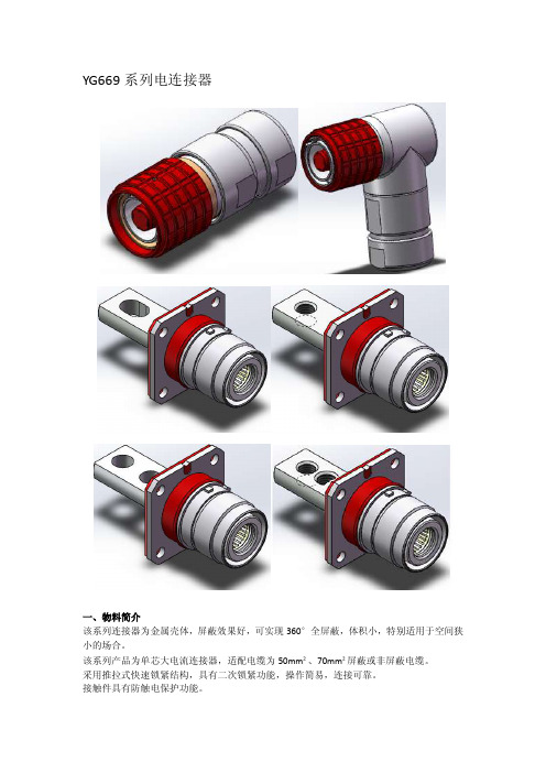
YG669系列电连接器一、物料简介该系列连接器为金属壳体,屏蔽效果好,可实现360°全屏蔽,体积小,特别适用于空间狭小的场合。
该系列产品为单芯大电流连接器,适配电缆为50mm²、70mm²屏蔽或非屏蔽电缆。
采用推拉式快速锁紧结构,具有二次锁紧功能,操作简易,连接可靠。
接触件具有防触电保护功能。
防错插:同时具备结构防误和视觉防误两种措施,结构上采用多键位防止错插设计,连接器外部通过不同颜色的配置实现视觉防错。
防护等级高,插头与插座配合后,防护等级达IP67 如有特殊要求,请咨询四川永贵公司相关人员,我们将为你提供相关设计方案及技术规格书二、技术参数 1、电气特性额定电流:220A (50mm ²),270A (70mm ²) 额定电压:630 AC/DC 耐电压:3000V AC 接触电阻:≤0.2mΩ绝缘电阻:≥5000 M Ω(常态),≥500 M Ω(湿热) 2、机械特性3、工作环境:工作温度:-40℃~+125℃湿度:≤80%(温度为40±2℃)三、型号命名方式 插头:设计序列号:YG669插针:P接触件数量:1直插头: P 弯插头:PW 接触件端接形式,压接:Y适用电缆截面积(单位:mm2)屏蔽:P防错插色带颜色:R:红、G:绿、B:蓝、H:黑、Y:黄防错插键位角度:W:45°、X:90°Y:135°、Z:180°插座:Φ8设计序列号:YG669插孔:S接触件数量:1插座: R接触件端接形式:压接:Y连接铜排连接:T 连接接线端子:D尾部端接形式描述:M8螺钉过孔:Φ8M8螺纹孔:M8防错插色带颜色:R:红、G:绿、B:蓝、H:黑、Y:黄防错插键位角度:W:45°、X:90°Y:135°、Z:180°屏蔽:P安装方式:法兰安装:F四、外形尺寸插头:插座。
动力电池高压连接器(单芯)技术规范
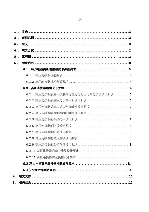
目录1 、目的 (2)2 、适用范围 (2)3 、定义 (2)4 、职责分配 (2)5 、流程图 ........................................................ . (2)6 、程序内容 ..................................................... .. (2)6.1 动力电池高压连接器技术参数要求 (3)6.1.1 高压连接器性能要求 (4)6.1.2 高压连接器技术参数要求 (4)6.2 高压连接器结构设计要求 (5)6.2.1 高压连接器插座中接触件与动力电池主电路连接端设计要求 (7)6.2.2 高压连接器插座固定于箱体面设计要求 (7)6.2.3 高压连接器插座与插头连接触件设计要求 (7)6.2.4 高压连接器插件的绝缘防触摸设计要求 (8)6.2.5 高压连接器的保护壳体设计要求 (8)6.2.6 高压连接器的防呆设计要求 (8)6.2.7 高压连接器的防呆设计要求 (8)6.2.8 高压连接器的高压互锁设计要求 (9)6.2.9 高压连接器的温控互锁设计要求 (9)6.2.10 高压连接器的动力线缆设计要求 (9)6.2.11 高压连接器的互换性设计要求 (9)6.3 动力电池高压连接器检验标准要求 (11)6.4供应商送样承认要求 (13)7、相关文件 (13)8、相关记录 (13)1 目的 Objectives: :汽车产业是国民经济的重要支柱产业,在国民经济和社会发展中发挥着重要作用,随着我国经济持续快速发展和城镇化进程加速推进,今后较长一段时期汽车需求仍将保持增长势头,由此带来的能源紧张和环境问题更加突出,加快培育和发展节能汽车与新能源汽车,即是有效缓解能源和环境压力,推动汽车产业可持续的紧迫任务,也是加快汽车产业转型升级、培育新的经济增长点和国际竞争优势的战略举措。
新能源电动汽车产业正是在这一时代背景下应运而生,动力总成作为整个新能源汽车的核心,如何保证其安全稳定显得尤为重要。
Molex 76650-0225 电路板电缆连接器说明书

Datasheet for 76650-02253, 4 and 6 Circuits Product HighlightsWire size:28-22 AWG(1.5 - 3) Amps depending on AWG 250 Volts Voltage:Current:Features and BenefitsApplications • Data communication equipment • Printers and faxes • PCs and monitors • Automotive • Friction lock provides good matingretention• Box-style contact protects contact area• Polarizing features ensures propermating• Guide rails and molded ledgesfacilitates mating and unmating Receptacle and Header Vertical General InformationMolex / Waldom Wire-to-Board 2.50mm (.098")Kit assembled in U.S.A.Description:Product Family:Pitch:Mini-Latch connectors provide a reliable interface for industry-standard 2.50mm(.098" ) wire-to-board applications. The system includes a box-style contactdesign and housing-side terminal latch to provide protection to the contact areaduring and after assembly. The durable housing also includes guide rails andmolded tabs to facilitate mating and unmating.Manufacturer:Country of Origin:Mini-Latch™Certificates:Friction Lock Vertical Header and Receptacle (Molex parts within this kit) - EU and China RoHS Compliant, UL and CSA Circuit Sizes:MountingOrientation:Connector Type:SpecificationsPart Number:DesignConfiguration:76650-0225Title:Mini-Latch Connector KitDatasheet for 76650-0225Molex Part No.Quantity in Kit 50802-91016551191-0300551191-0400551191-0600522-04-1031522-04-1041522-04-10615Molex Part No.63811-5200 *Japan Bill of Materials for Part No. 76650-0225Mini-Latch™ Female Crimp Terminals 28-22 AWG Countryof OriginDescription 2.50mm (.098") Pitch Mini-Latch™ Receptacles, 6 Circuits 2.50mm (.098") Pitch Vertical Header 3 Circuits 2.50mm (.098") Pitch Vertical Header 6 Circuits Japan 2.50mm (.098") Pitch Vertical Header 4 Circuits 2.50mm (.098") Pitch Mini-Latch™ Receptacles, 4 Circuits China Japan *Tool(s) not included in kit. Tool(s) ordered separately.Recommended Molex Tool(s) for Part No. 76650-0225*Countryof OriginDescriptionHand Crimp Tool Germany China 2.50mm (.098") Pitch Mini-Latch™ Receptacles, 3 Circuits Japan ChinaMouser ElectronicsAuthorized DistributorClick to View Pricing, Inventory, Delivery & Lifecycle Information:M olex:76650-0225。
连接器规格参数

连接器规格参数1、板对线连接器SF特点●端⼦呈箱型,接触点部分采⽤对⾯突出构造,实现了⾼度连接可信性●便于电路板印刷的设计,7.5mm间距、同时实际安装状态的⾼度为16.2mm,厚度为10mm,实现了规格电流10A的要求。
●Housing锁扣采⽤牢固的Positive Lock、端⼦保持部分采⽤Housing Lance构造。
实现了稳定的连接传导性能●防⽌逆向咬合·逆向插⼊构造,采⽤可防⽌排线扯扭⽽造成的接触不良的箱型,Wafer PIN为压⼊式构造,可完全防⽌溶剂进⼊。
SF规格极数2·3·4P极间间距7.5mm定额电压AC.DC300V定额电流10A耐电压AC1500V/1分绝缘抵抗1000MΩ以上使⽤温度范围-25~+105℃对应P.C.B板厚度 1.2~1.6mm对应P.C.B板孔径φ1.7mmSH特点●防⽌插⼊失误的构造●反复插⼊拆卸也保持其可靠性●⼩型化设计SH规格极数2~6P极间间距 5.0mm定额电压AC.DC250V定额电流5A耐电压AC1500V/1分绝缘抵抗1000MΩ以上使⽤温度范围-25~+85℃对应P.C.B板厚度 1.6mm对应P.C.B板孔径φ1.7mmSRV特点●Housing锁扣采⽤Inner Lock、端⼦保持部分采⽤Housing Lance构造。
实现了稳定的连接传导性能。
●通过采⽤保持架(选配)、利⽤双重防脱构造进⼀步提⾼了安全性。
●因可以同线对线RV连接器共⽤Plug Housing,所以如果是在同⼀零件和同⼀电路上根据构造区分使⽤板对线和线对线连接器时,可以共⽤电线●配套了可封装的WaferSRV规格极数2~4·6·8·12·16P极间间距 4.2mm定额电压AC.DC300V定额电流10A耐电压AC1500V/1分绝缘抵抗1000MΩ以上使⽤温度范围-25~+105℃对应P.C.B板厚度 1.2~1.6mm对应P.C.B板孔径φ1.7mmSV特点●因为是3.96mm间距,实现了实际安装嵌⼊状态下的⾼度为16.2mm、厚度10mm、规格电流10A ●端⼦呈箱型,接触点部分采⽤对⾯突出构造,实现了⾼度连接可信性●Housing锁扣采⽤牢固的Positive Lock、端⼦保持部分采⽤Housing Lance构造。
连接器规格书

60.28 56.32 52.36 48.40 44.44 40.48 36.52 32.56 28.60 24.64 20.68 16.72 12.76 8.60
B
PA66 UL94V-2 PA66 UL94V-2 PA66 UL94V-2 PA66 UL94V-2 PA66 UL94V-2 PA66 UL94V-2 PA66 UL94V-2 PA66 UL94V-2 PA66 UL94V-2 PA66 UL94V-2 PA66 UL94V-2 PA66 UL94V-2 PA66 UL94V-2 PA66 UL94V-2
赵崇本
Page 2 of 9
上海旨宏实业有限公司
产品规格书 Product Specification
编号 Serial number
版本号 Version Number
产品名称 Product Name
产品编码 Part Number
PS0123
3
TJC6 型条形连接器 Tjc6 PrssureWelding Bar Connector
备注 Mark
2~15
3适用线规 Applicable wiers
AWG22#~18#
4 适用基板厚度 Applicable PC board thickness
(1.2~1.6)mm
5 温度范围 Temperature range
-25°~85°
6 额定电压 Voltage rating
250V,AC,DC
视力:1.0 以上
1
外观 Appearance
Light: > 1.0 照明:200~300Lx
Lamp: 200 to 300Lx
目测距离:0.3~0.5m
CT63-1412技术规格书

编号:013-00014332CT63-1412TK/ZJ(XX)-01连接器技术规格书中航光电科技股份有限公司2011年10月CT63-1412TK/ZJ(XX)-01连接器技术规格书1.订货型号插头CT63-1412TK(XX)-01,插座CT63-1412ZJ(XX)-012.产品描述基本情况符合企业标准Q/21EJ1032-2009, 型号中括号内字母表示键位颜色,可以改变的颜色有蓝色、黑色、红色、绿色、黄色,对应代码分别为BL、BK、RE、GR、YE,譬如键位颜色为红色时,插头和插座型号分别为CT63-1412TK(RE)-01、CT63-1412ZJ(RE)-01,插头、插座为卡口式快速连接,分离时旋转插头上的螺帽分开,操作方便快捷,该连接器装12芯16号压接针孔件,头座对插并压接导线后能达到IP67防护等级。
3.产品性能3.1电气特性额定电流: 13A;工作电压:500VAC绝缘电阻:≥5000 MΩ(常温)耐电压:1500V AC(常温)3.2机械特性机械寿命:500 次3.3材料及表面处理接触件零件材料:铜合金生产工艺:机加表面处理:镀金壳体件零件材料:铝合金生产工艺:机加连接螺帽、方盘壳体表面处理:硬质阳极化其余外壳体表面处理:镀镍绝缘件零件材料:热塑性塑料生产工艺:注射成型弹性件零件材料:合金钢生产工艺:绕制3.4工作环境温度: -40℃~125℃振动:10Hz~500Hz 加速度:100 m/s23.5适配线缆0.5~0.85mm2;0.5mm2导线外径标称1.0mm,0.85mm2导线外径标称1.2mm;实际测量0.5mm2导线绝缘层外径为1.6mm~1.65mm,0.85mm2导线绝缘层外径为1.8mm~1.8 5mm。
4.外形尺寸:插头外形尺寸:Φ29.2×44.1接点排列图插座外形尺寸图:Φ38×32.2面板开口尺寸为:符合ROHS。
GB4706系列标准释义(16)通用要求部分——电源连接和外部软线
GB4706系列标准释义(16)通用要求部分——电源连接和外部软线GB4706系列标准释义(16)通用要求部分——电源连接和外部软线标准?检测?认证Jsfandards厂resfjng,certmcatjonJ26/27GB4706系列标准释义(16) 通用要求部分—一电源连接和外部软线余暇(续接本刊2007年第12期第29页) 标准原文(略)25电源连接和外部软线【释义】1外部软线一般用于器具的电源连接,用于连接器具外部不同电气部件的导线也属于外部软线.2与内部导线的区别是,外部软线暴露于器具外,其使用环境和可能受到的来自各方面的应力远远恶劣和大于内部导线.因此,外部软线应能抵御可能出现的机械, 热,潮湿等不利因素的影响.3根据使用状态和体积的不同,器具的电源连接可分为两种:?永久性与建筑物中提供的电源固定布线连接.一般这样的器具都是体积较大,安装入位后在正常使用中不再移动的驻立式(包括固定式,固定安装式,嵌入式)器具,如,一些供公共场所使用的自动售卖机,商用器具,家用空调机,嵌入式烤箱/微波炉.?非永久性与建筑物中提供的电源固定布线连接而通过其它方式与电网电源连接.手持式,便携式及其它非驻立式器具多采用这种连接方式,如,电吹风,电饭锅和电风扇.4本标准为非永久性与建筑物中提供的电源固定布线连接的器具规定了三种方案: ?通过一根带有电源插头的电源软线连接电源.电源插头应插入建筑物上安装的或在其它构件上安装的电网输出插座上.?通过一个至少与器具防水等级要求相同的器具输入插1:3连接电源.器具输入插口和与之配合使用的"插销"构成一副耦合器.耦合器的另一端带有一个电源插头,二者通过一根软线连接.电饭锅大多采用这种方式.?通过器具自带的插脚插入电网输出插座.使用这种方式的器具都是体积较小,重量较轻的器具,如,电池充电器,电动剃须刀.5器具的电源连接方式?永久性与固定布线连接a接线端子b电源引线?非永久性与固定布线连接a电源软线一X型连接一Y型连接一Z型连接b器具插口C器具插脚标准原文f选)25.6插头均不应该装有多于一根的柔性软线.【释义】并非要求必须使用不可重接插头.若使用可重接插头,则插头应符合整机标准的一些要求,如:材料的耐热,耐燃,耐漏电起痕性能;爬电距离,电气间隙和穿通绝缘距离;防触电保护措施和防水措施;电源软线紧固措施等.标准原文(选)25_7电源软线不应轻于规定规格 ,器具的结构使得电源软线在正常使用中不可能触及上述那些金属部件; 一电源软线是适合于高温的,在这种情况下,应使用Y型连接或Z型连接方式. 【释义】l"不应轻于×××"的意思是,所选用的电源软线的机械性能,电气绝缘性能以及耐热性能等不能低于规定牌号线的规定限值.2若器具的结构能保证在正常使用电源软线时不可能触及金属部件,则可以使用聚氯乙烯护套线.3第二条要求的目的是出于防止用户或非专业人员随意或无知地用普通电源软线更换原来的耐高温电源软线.因为x型连接的结构不能防止用户或非专业人员进行电源软线的更换.4常见的聚氯乙烯护套线的耐温等级有 75K和105K等.标准原文(选)25.8电源软线的导线,应具有不小于表11 中所示的标称横截面积.【释义】l选择电源软线"牌号"的主要依据是器具的质量,确定电源软线截面积的主要依栏目责任编辑,张磊,stheazhanglei@据是器具的额定电流.当质量依据和额定电流依据有冲突时,应服从要求高者.如, 吸油烟机的质量超过3kg,其额定电流不超过3A,依据前者,确定电源软线"牌号" 为普通聚氯乙烯护套软线GB5023.1的53 号线,依据后者,其横截面积应为0.5mm, 但53号线的最小横截面积为0.75mm, 此只能选择0.75mm的软线.2选择电源软线的横截面积的目的是使器具所用的电源软线的标称横截面积符合表中规定.传统的试验规范存在一个理解上的误区:确定器具的额定电流后,再去测量所片{电源软线实际的横截面积,因此便产生了实测值与限定值两者之间相差0.1mm 甚至0.01mm的"不合格".应往意到,无论是上述表中的规定还是对电源软线的要求,都以"标称值"相称.因此,正确的理解和做法是,在设计器具或对器具进行型式试验时,应遵循"器具的要求","电源软线的标称值","电源软线的合格证明"的思维方式对电源软线进行可用性或符合性确认.即,根据器具额定电流的大小,明确电源软线所需横截面积的标称限值,再检查所选择的电源软线的标称值是否符合器具要求的限定值,然后通过检查所选择电源软线的合格证明以确认电源软线符合相应标准的要求.作为制造商,用何手段控制供应商提供的电源软线的质量呢?至少可以?靠协议;?靠事先双方确认的实物样品(不妨用"数根数"的方法确定实物样品).3电源软线的工作环境是恶劣的,不但要承受电应力,还要承受正常和非正常使用中可能出现的机械应力(如,拉拽,踩匿等) 和热应力(如,暴晒,烘烤等)以及化学应力(如,酸碱物等).仅从应付上述机械应力来看,本标准确定导线横截面积时,考虑机械应力要比考虑电应力更多些.从材料手册不难发现,上表中同样横截面积的导线所能通过的电流随远大于表中规定. 标准原文(f)25.15带有电源软线的器具,以及打算用柔性软线永久连接到固定布线的器具,应有软线固定装置,该软线固定装置应使导线在接线端处免受拉力和扭矩,并保护导线的绝缘免受磨损.应不可能将软线推入器具,以致于损坏软线或器具内部部件的情况.【释义】l外部应力包括拉力,推力和扭力. 2防止来自外部的推力将导线推人器具, 往往依赖于紧固装置的结构和该装置与导线人线口的位置关系.3将紧固装置和导线人13合成为一体的结构形式是有效防止外部推力作用的方法. 4将紧固装置设置在导线入口处较近的地方也可以起到相同作用.5本标准强调的是,防止对内部导线或元件的伤害.因此,若器具的结构使得在外导线人线口附近没有内部导线或元件, 则防止外导线被推人的措施就可不必十分严格.标准原文25-20对Y型连接和Z型连接的0类,0I 类.I器具,其电源软线的绝缘导线应使用基表绝缘与易触及的金属部件之间再次膈开:对lJ类器具.则应使用附加绝缘来隔开.这种绝缘可以用电源软线的护套,或其他方法来提供.通过视检.并通过有关的试验确定其是否合格.【释义】1对于现有器具和电源软线结构而言,器具不需要特别设计就可满足这条要求.无论0类,0I类,I器具还是II类器具,使用带护套电源软线即可满足要求.2需要注意的是,电源软线进入器具后的部分,仍然受本条限制.因此,需考虑"电源软线的绝缘导线"与易触及金属部件的有效隔离.简单的方法是,尽量减少剥离护套后的绝缘软线的长度,并对已经剥离护套的绝缘软线与易触及金属部件实施有效隔离(如,捆绑或固定或靠一定的空气距离隔离).『编辑/张磊j?全国采用国际标准工作会议于2007年12月19-2O日在北京召开.会议总结了2007年全国标准化工作.部署了明年的工作,并讨论了《采用国际标准管理办法》和《关于进一步加强采用国际标准工作的意见》.?2007~12月14E1.全国认证认可标准化技术委员会(Tc261)在北京举办了国家标准GB/T27025《检测和校准实验室能力的通用要求》(送审稿)审定会.送审稿获得一致通过.『编辑/张磊j。
IEC 60969
IEC 60969-2001国际标准1:1988版与1:1991 和2:2000修订版普通照明用自镇流灯的平安要求出版编号方式从1997年一月开始,所有的IEC出版发行物都会出现60000代码。
例如,IEC 34-1,现在的编号方式应该是 IEC 60034-1。
修订版IEC现在发行修订版本。
例如,出版编号为1.0,1.1和1.2,分别代表,原始版本,原始版本加第一次修订,原始版本加第一次修订和第二次修订。
IEC出版物的更多信息版物上的技术信息,IEC都会随时更新,以确保其内容是最新的技术成果。
关于出版的信息,除了最新出版物,修订版和正误表之外,还包括有效期〔见下面〕。
在下面同样可以找到关于技术委员会的工作原理和程序以及已经发行的刊物的信息。
目录前言 (5)第一局部—总那么1. 范围 (9)2. 定义 (9)第二局部—灯具要求3. 尺寸 (13)4. 测试环境 (13)5. 开始和提高 (13)6. 灯泡瓦数 (13)7. 光通量 (13)8. 色调 (15)9. 流明维持率 (15)10. 寿命 (15)11. 和声学〔在考虑汇中〕 (15)第三局部—顺从条件附件:测量灯泡特征的方法 (17)国际电工委员会普通照明用自镇流灯的平安要求序言1〕IEC〔国际电工委员会〕是一个全球性的国际组织,专门负责统一组成所有的国家性的电工委员会〔IEC国家委员会〕。
IEC的目标是提高和加强国际上关于电工和电子问题的合作与联系。
为了实现这一目标,除了其它的活动外,IEC还出版发行国际标准。
他们的各方面的准备受到技术委员会的支持;任何一个国家IEC委员会在这一领域的工作都能参与到这一项准备工作中来。
国际的,政府或非政府机构,和IEC有联系都可以参与到此准备工作中。
IEC 与ISO,据各自的达成的协议,有着紧密的合作关系。
2〕IEC在技术问题上所做出的最终协议或决定都代表着国际上在这一问题的共识,因为每一个技术委员会都在国家委员会中有代表。
- 1、下载文档前请自行甄别文档内容的完整性,平台不提供额外的编辑、内容补充、找答案等附加服务。
- 2、"仅部分预览"的文档,不可在线预览部分如存在完整性等问题,可反馈申请退款(可完整预览的文档不适用该条件!)。
- 3、如文档侵犯您的权益,请联系客服反馈,我们会尽快为您处理(人工客服工作时间:9:00-18:30)。
YG669系列电连接器
一、物料简介
该系列连接器为金属壳体,屏蔽效果好,可实现360°全屏蔽,体积小,特别适用于空间狭小的场合。
该系列产品为单芯大电流连接器,适配电缆为50mm²、70mm²屏蔽或非屏蔽电缆。
采用推拉式快速锁紧结构,具有二次锁紧功能,操作简易,连接可靠。
接触件具有防触电保护功能。
防错插:同时具备结构防误和视觉防误两种措施,结构上采用多键位防止错插设计,连接器外部通过不同颜色的配置实现视觉防错。
防护等级高,插头与插座配合后,防护等级达IP67
如有特殊要求,请咨询四川永贵公司相关人员,我们将为你提供相关设计方案及技术规格书
二、技术参数
1、电气特性
额定电流:220A(50mm²),270A(70mm²)
额定电压:630 AC/DC
耐电压:3000V AC
接触电阻:≤0.2mΩ
绝缘电阻:≥5000 MΩ(常态),≥500 MΩ(湿热)
2、机械特性
防护等级:IP67(头座对插)
3、工作环境:
工作温度:-40℃~+125℃
湿度:≤80%(温度为40±2℃)
三、型号命名方式
插头:
设计序列号:YG669
插针:P
接触件数量:1
直插头: P 弯插头:PW 接触件端接形式,压接:Y 适用电缆截面积(单位:mm2)屏蔽:P
防错插色带颜色:
R:红、G:绿、
B:蓝、H:黑、
Y:黄
防错插键位角度:
W:45°、X:90°
Y:135°、Z:180°
插座:
Φ8
设计序列号:YG669插孔:S
接触件数量:1
插座: R
接触件端接形式:压接:Y
连接铜排连接:T 连接接线端子:D
尾部端接形式描述:
M8螺钉过孔:Φ8
M8螺纹孔:M8
防错插色带颜色:
R:红、G:绿、
B:蓝、H:黑、
Y:黄
防错插键位角度:
W:45°、X:90°
Y:135°、Z:180°
屏蔽:P
安装方式:法兰安装:F
四、外形尺寸插头:
插座。
