EMIF06-MSD02N16;中文规格书,Datasheet资料
湿敏元器件管控规范
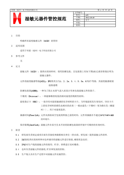
制作:官于审核:批准:1目的明确所有湿度敏感元件〈MSD〉的管控2适用范围适用于科盟(福州)电子科技有限公司3参考文件无4定义湿敏元件(MSD):指供应商来料时,使用防潮包装,且包装袋上有如下图1标记或有特别注明为湿敏元器件。
元件的湿度敏感等级(MSL):IPC将其分为1、2、2a、3、4、5、5a、6共8个等级,其湿度敏感级别逐级递增.防潮包装袋(MBB):一种为了阻止水蒸气进入而设计用来包装湿敏元件的袋子。
干燥剂(Desiccant):一种能够维持较低的相对湿度的吸附性材料。
湿度指示卡(HIC):一张印有对湿度敏感的化学材料的卡片,当环境湿度发生变化时,印在卡片上的化学材料的颜色也相应的改变〔一般由蓝色(干燥时)变为粉红色(潮湿时)〕,用于对湿度监控。
暴露时间(Floor Life): 元件从拆除真空包装到焊接之前的时间,元件须暴露在不超过30°C和60% RH的环境中。
保存限期(Shelf Life): 湿敏元件在真空且未开封的防潮包装袋的环境中可维持的有效时间。
5职责5.1研发部负责制定或项目部负责接收和跟催相关单位(供应商、研发部)提供湿敏元件清单.5.2IQC验收供应商来料和对仓库储存的湿敏元件进行检验,确保状态良好。
5.3IPQC对生产线的湿敏元件的使用、贮存、烘烤进行实时稽查。
5.4仓库负责湿敏元件的接收,贮存和发放的控制。
5.5生产线人员在生产过程中对湿敏元件实施管控。
制作:官于审核:批准:5.6工程部负责对湿敏元件清单的审核和转化为内部格式发行,负责对湿敏元件的管控提供技术支持。
6内容6.1湿敏元件识别:6.1.1检查元件外包装的标签, 如果在外包装标签上有如图1的雨滴状标识,可认定为湿敏元件。
6.1.2湿度指示卡的识别与说明6.1.2.1第一种湿度指示卡上有一“三角形箭头”(如下图2),其对应所指向的圆圈里化学物质若改变为粉红色则表示元件已受潮,需要烘烤。
6.1.2.2第二种湿度指示卡只有三个湿度等级的圆圈组成(如下图3),其使用说明如下表湿度指示卡(HIC)指示湿度环境为2%RH指示湿度环境为5%RH指示湿度环境为10%RH指示湿度环境为55%RH指示湿度环境为60%RH指示湿度环境为65%RH5% 蓝色淡紫色粉红色粉红色粉红色粉红色10% 蓝色蓝色淡紫色粉红色粉红色粉红色60% 蓝色蓝色蓝色蓝色淡紫色粉红色使用条件Level 2-5a可直接使用Level 2可直接使用Level 2a-5a需烘烤后方可使用Level 2-5a需烘烤后使用图1图2湿度指示卡颜色与使用要求对照表蓝色说明干燥,粉红色说明受潮了图3制作: 官于审核:批准:6.1.3 防潮包装袋上“Caution Label ”的内容介绍(见图4)6.2 湿敏元件等级的分级6.2.1 湿敏元件共分为8个等级:1、2、2a 、3、4、5、5a 、6,其湿度敏感级别逐级递增。
MMPQ2222A;FFB2222A;中文规格书,Datasheet资料

ON CHARACTERISTICS
hFE DC Current Gain IC = 0.1 mA, VCE = 10 V IC = 1.0 mA, VCE = 10 V IC = 10 mA, VCE = 10 V IC = 150 mA, VCE = 10 V* IC = 150 mA, VCE = 1.0 V* IC = 500 mA, VCE = 10 V* IC = 150 mA, IB = 15 mA IC = 500 mA, IB = 50 mA IC = 150 mA, IB = 15 mA IC = 500 mA, IB = 50 mA 35 50 75 100 50 40
*Pulse Test: Pulse Width ≤ 300 µs, Duty Cycle ≤ 2.0%
Spice Model
NPN (Is=14.34f Xti=3 Eg=1.11 Vaf=74.03 Bf=255.9 Ne=1.307 Ise=14.34f Ikf=.2847 Xtb=1.5 Br=6.092 Nc=2 Isc=0 Ikr=0 Rc=1 Cjc=7.306p Mjc=.3416 Vjc=.75 Fc=.5 Cje=22.01p Mje=.377 Vje=.75 Tr=46.91n Tf=411.1p Itf=.6 Vtf=1.7 Xtf=3 Rb=10)
Thermal Characteristics
Symbol
PD RθJA
TA = 25°C unless otherwise noted
Characteristic
Total Device Dissipation Derate above 25°C Thermal Resistance, Junction to Ambient Effective 4 Die Each Die FFB2222A 300 2.4 415
厚生电阻规格书
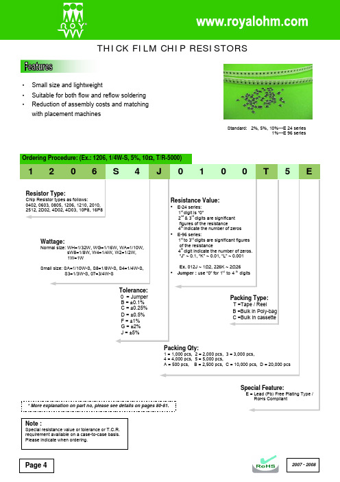
Page 4•Small size and lightweight• Suitable for both flow and reflow soldering •Reduction of assembly costs and matching with placement machines2007 - 2008Standard: 2%, 5%, 10%---E 24 series 1%---E 96 series2007 - 2008 Page 5Marking on the Resistors Body:•For 0402 size, no marking on the body due to the small size of the resistor.•±5% tolerance product. (Including resistance values less than 1Ω; both 1% and 5%) The marking is 3 digits, the first 2 digits are the significant figures of the resistance and the 3rd digit denotes number of zeros.153 = 15000Ω = 15KΩ; 120 = 12Ω Below 10Ω shown as this: 6R8 = 6.8Ω 0.1Ω~0.99Ω shown as this: R33 = 0.33Ω•±1% tolerance marking of case size 0805 and bigger is 4 digits, the first 3 digits are the significant figures of the resistance and the 4th digit denotes number of zeros.2372 = 23700Ω = 23.7KΩ; 1430 = 143Ω Below 10Ω shown as this: 3R24 = 3.24Ω0.1Ω~0.99Ω shown as this: R33 = 0.33ΩPage 62007 - 2008* More details, please see pages 78-79.• Standard E-96 series values (±1% tolerance) of 0603 size. Due to the small size of the resistor’s body, 3 digitsmarking will be used to indicate the accurate resistance value by using the Multiplier code & Standard E-96 Series Resistance Value Code as shown on Page 6.1.96K Ω = 196 x 101 Ω = 29B12.4Ω = 124 x 10-1 Ω = 10X• Standard E-24 series values which does not belong to E-96 series values (in ±1% tolerance) of 0603 size. The marking is the same as 5% tolerance but marked with underline.122 = 1200 = 1.2K Ω680 = 68ΩTemperature coefficient±5%: 1Ω ~ 10M Ω ≤ ±200PPM/°C±1%: 10Ω ~ 100Ω ≤ ±200PPM/°C; 101Ω ~ 1M Ω ≤ ±100PPM/°C Short-time overload ±5%: ±(2.0% + 0.1Ω) Max. ±1%: ±(1.0% + 0.1Ω) Max. Insulation resistanceMin. 1,000 Mega OhmDielectric withstanding voltageNo evidence of flashover, mechanical damage, arcing or insulation breakdown Terminal bending ±(1.0% + 0.05Ω) Max.Soldering heat Resistance change rate is ±(1.0% + 0.05Ω) Max. SolderabilityMin. 95% coverage Temperature cycling ±5%: ±(1.0% + 0.05Ω) Max. ±1%: ±(0.5% + 0.05Ω) Max. Humidity (Steady State) ±5%: ±(3.0% + 0.1Ω) Max. ±1%: ±(0.5% + 0.1Ω) Max. Load life in humidity±5%: ±(3.0% + 0.1Ω) Max. ±1%: ±(1.0% + 0.1Ω) Max. Load life±5%: ±(3.0% + 0.1Ω) Max.±1%: ±(1.0% + 0.1Ω) Max.* The values which are not of standard E-24 series (2% & 5%) and not of E-96 series (1%) could be offered on a case to case basis.2007 - 2008Page 72007 - 2008Page 8•16P8 (16Pin 8R)THICK FILM CHIP RESISTOR ARRAYS• High density 2, 4, 8 resistors in one small case (convex type) • Improvement of placement efficiency• Packaging is suitable for automatic placement machines • Superior solderability • Scalloped•2D02 (4Pin 2R)•4D02, 4D03 (8Pin 4R)•10P8 (10Pin 8R)Part No.StyleLWHℓ1ℓ2PQ2D02 (0402x2) 2D02 (4Pin 2R) 1.0 ± 0.1 1.0 ± 0.1 0.35 ± 0.1 0.17 ± 0.1 0.25 ± 0.1 0.65 ± 0.05 0.33 ± 0.1 4D02 (0402x4) 4D02 (8Pin 4R) 2.0 ± 0.1 1.0 ± 0.1 0.45 ± 0.1 0.2 ± 0.15 0.3 ± 0.15 0.5 ± 0.05 0.3 ± 0.05 4D03 (0603x4) 4D03 (8Pin 4R) 3.2 ± 0.2 1.6 ± 0.2 0.5 ± 0.1 0.3 ± 0.15 0.3 ± 0.15 0.8 ± 0.1 0.5 ± 0.15 16P8 16P8 (16Pin 8R) 4.0 ± 0.2 1.6 ± 0.15 0.45 ± 0.1 0.3 ± 0.15 0.4 ± 0.15 0.5 ± 0.05 0.3 ± 0.05 10P8 10P8 (10Pin 8R)3.2 ± 0.21.6 ± 0.150.55 ± 0.10.4 ± 0.10.3 ± 0.150.64 ± 0.050.35 ± 0.05Resistance RangePart No. StylePower Rating at 70ºC Max. Working Voltage Max. Overload VoltageDielectric With-standing VoltageOperated Temp. RangeF (±1%) E-96 seriesJ (±5%) E-24 seriesJumper Rated Current2D02 2D02 (4Pin2R) 1/16W 50V 100V 500V -55ºC~+155ºC - 10Ω~ 1M Ω - 4D02 4D02 (8Pin4R) 1/16W 50V 100V 500V -55ºC~+155ºC -10Ω~ 1M Ω -4D03 4D03 (8Pin4R) 1/16W 50V 100V 500V -55ºC~+155ºC 100Ω~560K Ω 10Ω~ 1M Ω 1A 16P8 16P8 (16Pin8R) 1/16W 50V 100V 100V -55ºC~+155ºC - 10Ω~ 1M Ω - 10P810P8 (10Pin8R)1/32W 25V 50V 50V -55ºC~+155ºC -33Ω~ 100K Ω -Note: Part number and ordering procedure the same as Thick Film Chip Resistors on Page 4.Standard: 2%, 5%, 10%---E 24 series 1%---E 96 series。
优恩半导体ESD静电保护器目录表

Part Number (Reference) ESD3.3V52D-A ESD05V52D-A ESD08V52D-A ESD12V52D-A ESD15V52D-A ESD24V52D-A ESD05V52D-C ESD12V52D-CInternal ConfigurationVrwm(V) 3.3 5 8 12 15 24 5 9Vbrmin(V)CJMAX 1MHz(pF) 200 110 70 60 50 25 10 5 450 200 30 100 75 50Peak Power Ir@Vrwm 8/20 µ s (µA) 120 120 120 120 120 120 100 100 320 320 100 320 320 320 200 5 5 5 5 5 1 1 40 10 1 1 1 1SOD-5234 6 8.5 13.3 16.6 26.7 6 10.2 4 6 6 13.3 16.7 26.7SOD-523 ESD03V32D-C ESD05V32D-C ESD0501V32D-C ESD12V32D-C ESD15V32D-C ESD24V32D-C 3 5 5 12 15 24SOD-323ESD3.3V32D-LA ESD05V32D-LA SOD-323 ESD03V32D-LC ESD05V32D-LC ESD08V32D-LC ESD12V32D-LC ESD15V32D-LC ESD24V32D-LC3.3 5.04 60.4 0.4350 35020 5SOD-3233.0 5.0 8.0 12.0 15.0 24.04.0 6.0 8.5 13.3 16.7 26.71.2 1.2 1.2 1.2 1.2 1.2350 350 350 350 350 35020 5 2 1 1 1ESD05V14TLC SOT-1435.06.01.23005Part Number (Reference) ESD03V23T-2A ESD05V23T-2A ESD05V23T-2AL ESD08V23T-2A ESD12V23T-2A ESD15V23T-2A ESD24V23T-2A ESD36V23T-2AInternal ConfigurationVrwm(V) 3.3 5.0 5.0 8.0 12.0 15.0 24.0 36.0Vbrmin(V)CJMAX 1MHz(pF) 400 300 30 250 150 100 88 60Peak Power Ir@Vrwm 8/20 µ s (µA) 300 300 100 300 300 300 300 300 100 10 0.1 1 1 1 1 1SOT-234.0 6.0 6.0 8.5 13.3 16.7 26.7 40.0ESD05V23T-2L SOT-23 Pin 3 to Pin1/Pin2 SM712 Pin 3 to Pin1/Pin2 ESD3.3V23T-1A ESD05V23T-1A ESD08V23T-1A ESD12V23T-1A ESD15V23T-1A ESD24V23T-1A ESD36V23T-1A SOT-235.06.01350177.555400107 3.3 5.0 8.0 12.0 15.0 24.0 36.013.3 4.0 6.0 8.5 13.3 16.7 24.0 40.055 5 5 5 5 5 5 5400 500 500 500 500 500 500 5001 40 5 5 1 1 1 1SOT-23SLVU2.8 SOT-232.83.034001ESD05V26T-4 SOT-265.06.01.23501Part Number (Reference) ESD05V26T-4L ESD12V26T-4L ESD15V26T-4L ESD24V26T-4LInternal ConfigurationVrwm(V)Vbrmin(V)CJMAX 1MHz(pF) 200 90 70 50Peak Power Ir@Vrwm 8/20 µ s (µA) 350 350 350 350 5 1 1 15.0 12.0 15.0 24.0 SOT-266.0 13.3 16.7 26.7ESD05V26T-5L ESD12V26T-5L ESD15V26T-5L ESD24V26T-5L SOT-265.0 12.0 15.0 24.06.0 13.3 16.7 26.7200 90 70 50350 350 350 3505 1 1 1ESD05V36T-4L SOT-3635.06.021501ESD05V36T-5L SOT-3635.06.0501001ESD05V56T-2L SOT-5635.06.00.9501ESD05V56T-4L SOT-5635.06.0301001ESD05V56T-5L SOT-5635.06.0301001Part Number (Reference)Internal ConfigurationVrwm(V)Vbrmin(V)CJMAX 1MHz(pF)Peak Power Ir@Vrwm 8/20 µ s (µA)ESD12V56T-2C SOT-5639.010.031001SLVU2.8-4 SO-082.83.024005SLVU2.8-8 SO-08 ESD06V08S-4L SO-082.83.0560056.06.825200020ESD05V08S-4L SO-08 LCDA05C-4 LCDA12C-4 LCDA15C-4 LCDA24C-45.06.0550010SO-085.0 12.0 15.0 24.06.0 13.3 16.7 26.75 5 5 5500 500 500 50020 1 1 1LCDA05C-8 LCDA12C-8 LCDA15C-8 LCDA24C-8 SO-165.0 12.0 15.0 24.06.0 13.3 16.7 26.75 5 5 5500 500 500 50020 1 1 1Part Number (Reference)Internal ConfigurationVrwm(V)Vbrmin(V)CJMAX 1MHz(pF)Peak Power Ir@Vrwm 8/20 µ s (µA)ESD05VDFN-C DFN10065.06.0101001ULC0524P DSON-105.06.00.81501ULC0528P5.06.50.52000.5MSOP-08ESD05V10S-4L MSOP-105.06.00.51251Cell Phone CCD Camera LinesEE0504K LWSON-085.06.020Color LCD Protection Clamshell Cell Phones0.5Cell Phone CCD Camera LinesESD0506K5.06.020Color LCD Protection Clamshell Cell Phones0.5LWSON-12Part Number (Reference)Internal ConfigurationVrwm(V)Vbrmin(V)CJMAX 1MHz(pF)Peak Power Ir@Vrwm 8/20 µ s (µA)Cell Phone CCD Camera LinesEE0508K5.06.020Color LCD Protection Clamshell Cell Phones0.5LWSON-16EE0508DFN5.06.0171DFN3014Differential Mode vs. Common Mode4345256162 of 211232011/3/31Curves of CharacterizationBAV99 vs TVS ARRAYS直接將突波導入到 Vcc -- 這種方式非 非 常不安全, 易導致 Vcc損害.直接將突波導入到 GND -- 這種方式非 非 常安全. 因為接地 區域有較大阻抗可 以分散突波.4 of 212011/3/31Parasitic InductanceESD ProtectorESD Protector不妥當的方式 : 無法將保護元件直接貼 在信號線上. 會產生寄 生電感. 造成保護能力 被寄生的電感減弱.安全的方式 : 將保護元件直接貼在信 號線上. 讓保護能力全 力發揮.Fine Layout vs Parasitic InductanceFine Layout -- Without Parasitic InductanceNOT recommation -- Parasitic Inductance7 of 212011/3/31Anti-Parasitic Inductance直接將保護ESD保護能力元件貼在信號線上--不會產生寄生電感問題.可以完全發揮8 of 212011/3/31Anti-Parasitic Inductance3-PIN產品的應用9 of 212011/3/31USB 3.0 Interface ProtectionMSOP-0810 of 212011/3/31HDMI Interface ProtectionSLP2510P8(2.5x1.0x0.5mm)11 of 212011/3/31USB 3.0 Interface Protection12 of 212011/3/31GR-1089 Lighting Protection for T-Carrier Interface13 of 212011/3/3110/1000 Gigabit Ethernet Protection14 of 212011/3/31。
CM1621-06DE;中文规格书,Datasheet资料
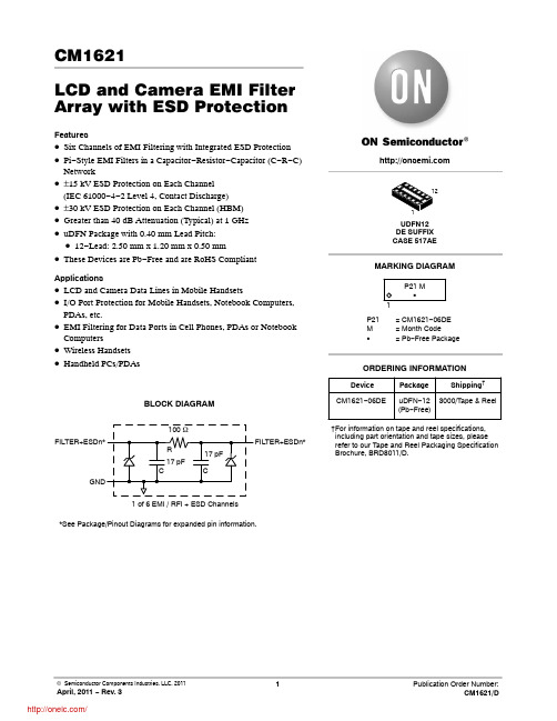
CM1621LCD and Camera EMI Filter Array with ESD ProtectionFeatures•Six Channels of EMI Filtering with Integrated ESD Protection •Pi −Style EMI Filters in a Capacitor −Resistor −Capacitor (C −R −C)Network•±15 kV ESD Protection on Each Channel (IEC 61000−4−2 Level 4, Contact Discharge)•±30 kV ESD Protection on Each Channel (HBM)•Greater than 40 dB Attenuation (Typical) at 1 GHz •uDFN Package with 0.40 mm Lead Pitch:•12−Lead: 2.50 mm x 1.20 mm x 0.50 mm•These Devices are Pb −Free and are RoHS CompliantApplications•LCD and Camera Data Lines in Mobile Handsets•I/O Port Protection for Mobile Handsets, Notebook Computers,PDAs, etc.•EMI Filtering for Data Ports in Cell Phones, PDAs or Notebook Computers•Wireless Handsets •Handheld PCs/PDAsBLOCK DIAGRAMFILTER+ESDn**See Package/Pinout Diagrams for expanded pin information.1 of 6 EMI / RFI + ESD ChannelsMARKING DIAGRAMDevicePackage Shipping †ORDERING INFORMATIONCM1621−06DEuDFN −12(Pb −Free)3000/T ape & ReelUDFN12DE SUFFIX CASE 517AE†For information on tape and reel specifications,including part orientation and tape sizes, please refer to our Tape and Reel Packaging Specification Brochure, BRD8011/D.P21= CM1621−06DE M = Month CodeG= Pb −Free Package1P21 M GPACKAGE / PINOUT DIAGRAMSBottom View (Pins Up View)Top View (Pins Down View)12−Lead UDFN PackagePin 1Marking14 13 12 11 10 91 2 3 4 5 6Table 1. PIN DESCRIPTIONSDevice Pin(s)Name DescriptionDevice Pin(s)Name Description1FILTER1Filter + ESD Channel 112FILTER1Filter + ESD Channel 12FILTER2Filter + ESD Channel 211FILTER2Filter + ESD Channel 23FILTER3Filter + ESD Channel 310FILTER3Filter + ESD Channel 34FILTER4Filter + ESD Channel 49FILTER4Filter + ESD Channel 45FILTER5Filter + ESD Channel 58FILTER5Filter + ESD Channel 56FILTER6Filter + ESD Channel 67FILTER6Filter + ESD Channel 6GND PADGNDDevice GroundSPECIFICATIONSTable 2. ABSOLUTE MAXIMUM RATINGSParameterRating Units Storage Temperature Range −65 to +150°C DC Power per Resistor 100mW DC Package Power Rating500mWStresses exceeding Maximum Ratings may damage the device. Maximum Ratings are stress ratings only. Functional operation above the Recommended Operating Conditions is not implied. Extended exposure to stresses above the Recommended Operating Conditions may affect device reliability.Table 3. STANDARD OPERATING CONDITIONSParameterRating Units Operating Temperature Range−40 to +85°CTable 4. ELECTRICAL OPERATING CHARACTERISTICS (Note 1)Symbol Parameter Conditions Min Typ Max Units R Resistance85100115WC TOTAL Total Channel Capacitance At 2.5 VDC Reverse Bias,1 MHz, 30 mVAC273441pFC Capacitance C At 2.5 VDC Reverse Bias,1 MHz, 30 mVAC17pF V DIODE Standoff Voltage I DIODE = 10 m A 6.0V I LEAK Diode Leakage Current (reverse bias)V DIODE= +3.3 V100nA V SIG Signal Clamp Voltage I LOAD = 1.0 mA 6.07.08.0VV ESD In−system ESD Withstand Voltagea) Human Body Model (HBM), MIL−STD−883,Method 3015b) Contact Discharge per IEC 61000−4−2 Level 4(Note 2)±30±15kVR DYN Dynamic ResistancePositiveNegative 2.30.9Wf C Cut−off FrequencyZ SOURCE = 50 W, Z LOAD = 50 W Channel R = 100 W,Channel C = 15 pF90135(Note 3)MHzA1GHz Absolute Attenuation at 1 GHz from 0 dB Level Z SOURCE = 50 W, Z LOAD = 50 W,DC Bias = 0 V; (Notes 1 and 3)−40dBA800MHz −3GHz Absolute Attenuation at 800 MHz to 3 Ghzfrom 0 dB LevelZ SOURCE = 50 W, Z LOAD = 50 W,DC Bias = 0 V; (Notes 1 and 3)−35dB1.T A= 25°C unless otherwise specified.2.ESD applied to input and output pins with respect to GND, one at a time.3.Attenuation / RF curves characterized by a network analyzer using microprobes.PERFORMANCE INFORMATIONTypical Filter Performance (T A = 255C, DC Bias = 0 V, 50 W Environment)Figure 1. Insertion Loss vs. Frequency (FILTER1 Input to GND, CM1621−06DE)Typical Diode Capacitance vs. Input VoltageFigure 2. Insertion Loss vs. Frequency (FILTER2 Input to GND, CM1621−06DE)Typical Diode Capacitance vs. Input VoltageFigure 3. Insertion Loss vs. Frequency (FILTER3 Input to GND, CM1621−06DE) Typical Diode Capacitance vs. Input VoltageFigure 4. Insertion Loss vs. Frequency (FILTER4 Input to GND, CM1621−06DE) Typical Diode Capacitance vs. Input VoltageFigure 5. Insertion Loss vs. Frequency (FILTER5 Input to GND, CM1621−06DE) Typical Diode Capacitance vs. Input VoltageFigure 6. Insertion Loss vs. Frequency (FILTER6 Input to GND, CM1621−06DE) Typical Diode Capacitance vs. Input VoltageFigure 7. Filter Capacitance vs. Input Voltage (normalized to capacitance at 2.5 VDC and 255C)C a p a c i t a n c e (N o r m a l i z e d )DC VoltagePACKAGE DIMENSIONSUDFN12, 2.5x1.2, 0.4P CASE 517AE −01ISSUE BNOTES:1.DIMENSIONING AND TOLERANCING PER ASME Y14.5M, 1994.2.CONTROLLING DIMENSION: MILLIMETERS.3.DIMENSION b APPLIES TO PLATED TERMINAL AND IS MEASURED BETWEEN 0.25 AND 0.30 mm FROM TERMINAL.4.COPLANARITY APPLIES TO THE EXPOSED PAD AS WELL AS THE TERMINALS.12XSEATINGPLANEL12XDIM MIN NOM MAX MILLIMETERS A 0.450.500.55A10.000.030.05A30.127 REF b 0.150.200.25D 2.50 BSC D2 1.70 1.80 1.90E 1.20 BSC E20.200.300.40e 0.40 BSC K 0.20−−−−−−L0.200.250.300.40*For additional information on our Pb −Free strategy and soldering details, please download the ON Semiconductor Soldering and Mounting Techniques Reference Manual, SOLDERRM/D.SOLDERING FOOTPRINT*ON Semiconductor and are registered trademarks of Semiconductor Components Industries, LLC (SCILLC). SCILLC reserves the right to make changes without further notice to any products herein. SCILLC makes no warranty, representation or guarantee regarding the suitability of its products for any particular purpose, nor does SCILLC assume any liability arising out of the application or use of any product or circuit, and specifically disclaims any and all liability, including without limitation special, consequential or incidental damages.“Typical” parameters which may be provided in SCILLC data sheets and/or specifications can and do vary in different applications and actual performance may vary over time. All operating parameters, including “Typicals” must be validated for each customer application by customer’s technical experts. SCILLC does not convey any license under its patent rights nor the rights of others. SCILLC products are not designed, intended, or authorized for use as components in systems intended for surgical implant into the body, or other applications intended to support or sustain life, or for any other application in which the failure of the SCILLC product could create a situation where personal injury or death may occur. Should Buyer purchase or use SCILLC products for any such unintended or unauthorized application, Buyer shall indemnify and hold SCILLC and its officers, employees, subsidiaries, affiliates,and distributors harmless against all claims, costs, damages, and expenses, and reasonable attorney fees arising out of, directly or indirectly, any claim of personal injury or death associated with such unintended or unauthorized use, even if such claim alleges that SCILLC was negligent regarding the design or manufacture of the part. SCILLC is an Equal Opportunity/Affirmative Action Employer. This literature is subject to all applicable copyright laws and is not for resale in any manner.PUBLICATION ORDERING INFORMATION分销商库存信息: ONSEMICM1621-06DE。
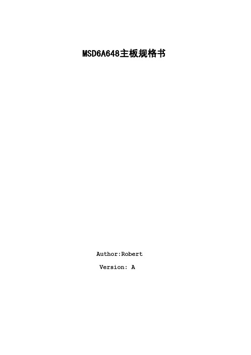
MSD6A648主板规格书
SorensonH.26 3
1080P@30fps
H.263
1080p@30fps
40Mbps 40Mbps
H.264
1080Px2@30fps 1080P@60fps
62.5Mbp s
.MainProfile .HighProfile
入阻抗
Video system
视频制式
ATV
sound System
声音制式
PAL DK/BG/I
Max storage Channels
最大存台数
ATV:1-255
Receiving Range 接收范围
VHF(52.5MHZ-219MHZ)
Input impedance 输 75Ω
入阻抗
Channel Bandwidth 带宽
3GPP(.3gpp,.3gp) MPEGtransportstream
(.ts,.trp,.tp) MKV(.mkv)
62.5Mbps
50Mbps
Jizhunprofile@ Level6.0
60Mbps 40Mbps
Broadcasting profile@Level 6.0.1.08.60
MPEGtransportstream(.ts,.trp, .tp) 3GPP(.3gpp,.3gp) MP4(.mp4,.mov) MP Gtransportstream (.ts,.trp,.tp) 3GPP(.3gpp,.3gp) MP4(.mp4,.mov) MPEGtransportstream (.ts,.trp,.tp) ASF(.asf) AVI(.avi) MKV(.mkv) WMV(.wmv)
MB85RC16PNF-G-JNE1;中文规格书,Datasheet资料

FUJITSU SEMICONDUCTORDATA SHEETCopyright©2011 FUJITSU SEMICONDUCTOR LIMITED All rights reserved 2011.6Memory FRAM16 K (2 K × 8) Bit I 2CMB85RC16■DESCRIPTIONThe MB85RC16 is an FRAM (F erroelectric Random Access Memory) chip in a configuration of 2,048 words × 8 bits, using the ferroelectric process and silicon gate CMOS process technologies for forming the nonvolatile memory cells.Unlike SRAM, the MB85RC16 is able to retain data without using a data backup battery.The memory cells used in the MB85RC16 have at least 1010 Read/Write operation endurance per bit, which is a significant improvement over the number of read and write operations supported by other nonvolatile memory products.The MB85RC16 can provide writing in one byte units because the long writing time is not required unlike Flash memory and E 2PROM. Therefore, the writing completion waiting sequence like a write busy state is not required.■FEATURES•Bit configuration : 2,048 words × 8 bits •Operating power supply voltage : 2.7 V to 3.6 V •Operating frequency : 1 MHz (Max) •T wo-wire serial interface : Fully controllable by two ports: serial clock (SCL) and serial data (SDA).•Operating temperature range : − 40 °C to + 85 °C •Data retention : 10 years ( + 75 °C) •Read/Write endurance : 1010 times •Package : Plastic / SOP , 8-pin (FPT -8P-M02)•Low power consumption : Operating current 0.1mA (Max: @1 MHz), Standby current 0.1 μA (Typ)DS501-00001-2v0-EMB85RC16■PIN FUNCTIONAL DESCRIPTIONSPinNumberPin Name Functional Description1 to 3NC Unconnected pins Leave it unconnected.4VSS Ground pin5SDA Serial Data I/O pinThis is an I/O pin of serial data for performing bidirectional communication of mem-ory address and writing or reading data. It is possible to connect some devices. It is an open drain output, so a pull-up resistance is required to be connected to the external circuit.6SCL Serial Clock pinThis is a clock input pin for input/output timing serial data. Data is sampled on the rising edge of the clock and output on the falling edge.7WP Write Protect pinWhen Write Protect pin is “H” level, writing operation is disabled. When Write Pro-tect pin is “L” level, the entire memory region can be overwritten. Reading operation is always enabled regardless of the Write Protect pin state. The write protect pin is internally pulled down to VSS pin, and that is recognized as “L” level (the state that writing is enabled) when the pin is the open state.8VDD Supply Voltage pinMB85RC16■I2C (Inter-Integrated Circuit)The MB85RC16 has the two-wire serial interface and the I2C bus, and operates as a slave device.The I2C bus defines communication roles of “master” and “slave” devices, with the master side holding the authority to initiate control. Furthermore, a I2C bus connection is possible where a single master device is connected to multiple slave devices in a party-line configuration.2MB85RC16■I2C COMMUNICATION PROTOCOLThe I2C bus provides communication by two wires only, therefore, the SDA input should change while SCL is the “L” level. However, when starting and stopping the communication sequence, SDA is allowed to change while SCL is the “H” level.•Start ConditionTo start read or write operations by the I2C bus, change the SDA input from the “H” level to the “L” level while the SCL input is in the “H” level.•Stop ConditionTo stop the I2C bus communication, change the SDA input from the “L” level to the “H” level while the SCL input is in the “H” level. In the reading operation, inputting the stop condition finishes reading and enters the standby state. In the writing operation, inputting the stop condition finishes inputting the rewrite data.Note : The FRAM device does not need the programming wait time (t WC) after issuing the Stop Condition during the write operation.MB85RC16■ACKNOWLEDGE (ACK)In the I2C bus, serial data including memory address or memory information is sent in units of 8 bits. The acknowledge signal indicates that every 8 bits of the data is successfully sent and received. The receiver side usually outputs the “L” level every time on the 9th SCL clock after every 8 bits are successfully trans-mitted. On the transmitter side, the bus is temporarily released on this 9th clock to allow the acknowledge signal to be received and checked. During this released period, the receiver side pulls the SDA line down to indicate that the communication works correctly.If the receiver side receives the stop condition before transmitting the acknowledge “L” level, the read operation ends and the I2C bus enters the standby state. If the acknowledge “L” level is not detected, and the Stop condition is not sent, the bus remains in the released state without doing anything.■MEMORY ADDRESS STRUCTUREThe MB85RC16 has the memory address buffer to store the 11-bit information for the memory address.As for byte write, page write and random read commands, the complete 11-bit memory address is configured by inputting the memory upper address (3 bits) and the memory lower address (8 bits), and saving to the memory address buffer and access to the memory is performed.As for a current address read command, the complete 11-bit memory address is configured by inputting the memory upper address (3 bits) and by the memory address lower 8-bit which has saved in the memory address buffer, and saving to the memory address buffer and access to the memory is performed.MB85RC16■DEVICE ADDRESS WORDF ollowing the start condition, the 8 bit device address word is input. Inputting the device address word decideswhether the master or the slave drives the data line. However, the clock is always driven by the master. The device address word (8bits) consists of a device T ype code (4bits), memory upper address code (3bits), anda Read/Write code (1bit).•Device Type Code (4bits)The upper 4 bits of the device address word are a device type code that identifies the device type, and are fixed at “1010” for the MB85RC16.•Memory Upper Address Code (3bits)Following the device type code, the 3 bits of the memory upper address code are input.The slave address selection is not performed by the external pin setting on this device. These 3 bits are not the setting bits for the slave address, but the upper 3-bit setting bits for the memory address.•Read/Write Code (1bit)The 8th bit of the device address word is the R/W (Read/Write) code. When the R/W code is “0” input, a write operation is enabled, and the R/W code is “1” input, a read operation is enabled for the MB85RC16. If the device code is not “1010”, the Read/Write operation is not performed and the standby state is chosen.MB85RC16■DATA STRUCTUREThe master inputs the device address word (8 bits) following the start condition, and then the slave outputs the Acknowledge “L” level on the ninth bit. After confirming the Acknowledge response, the sequential 8-bit memory lower address is input, to the byte write, page write and random read commands.As for the current address read command, inputting the memory lower address is not performed, and the address buffer lower 8-bit is used as the memory lower address.When inputting the memory lower address finishes, the slave outputs the Acknowledge “L” level on the ninth bit again.Afterwards, the input and the output data continue in 8-bit units, and then the Acknowledge “L” level is output for every 8-bit data.MB85RC16■FRAM ACKNOWLEDGE -- POLLING NOT REQUIREDThe MB85RC16 performs the high speed write operations, so any waiting time for an ACK* by the acknowl-edge polling does not occur.*: In E2PROM, the Acknowledge Polling is performed as a progress check whether rewriting is executed or not.It is normal to judge by the 9th bit of Acknowledge whether rewriting is performed or not after inputting the start condition and then the device address word (8 bits) during rewriting.■WRITE PROTECT (WP)The entire memory array can be write protected by setting the WP pin to the “H” level. When the WP pin is set to the “L” level, the entire memory array will be rewritten. Reading is allowed regardless of the WP pin's “H” level or “L” level.Do not change the WP signal level during the communication period from the start condition to the stop condition.Note : The WP pin is pulled down internally to VSS pin, therefore if the WP pin is open, the pin status is detected as the “L” level (write enabled).MB85RC16■COMMAND•Byte WriteIf the device address word (R/W “0” input) is sent after the start condition, an ACK responds from the slave.After this ACK, write memory addresses and write data are sent in the same way, and the write ends by•Page WriteIf data is continuously sent after the following address when the same command (expect stop condition) as Byte Write was sent, a page write is performed. The memory address rolls over to first memory address (000H)at the end of the address. Therefore, if more than 2 Kbytes are sent, the data is overwritten in orderMB85RC16•Current Address ReadIf the last write or read operation finishes correctly up to the end of stop condition, the memory address that was accessed last remains in the memory address buffer (the length is 11 bits).When sending this command without turning the power off, it is possible to read from the memory address n+1 which adds 1 to the total 11-bit memory address n, which consists of the memory upper address 3-bit from the device address word input and the lower 8-bit of the memory address buffer. If the memory address n is the last address, it is possible to read with rolling over to the head of the memory address (000H). The current address (address that the memory address buffer indicates) is undefined immediately after turning•Random ReadThe one byte of data from the memory address as saved in the memory address buffer can be read out synchronously to SCL by specifying the address in the same way as for a write, and then issuing another start condition and sending the Device Address Word (R/W “1” input).Setting values for the first and the second memory upper address codes should be the same.The final NACK (SDA is the “H” level) is issued by the receiver that receives the data. In this case, this bit is分销商库存信息: FUJITSUMB85RC16PNF-G-JNE1。
薄膜贴片电阻器规格书_风华_FH
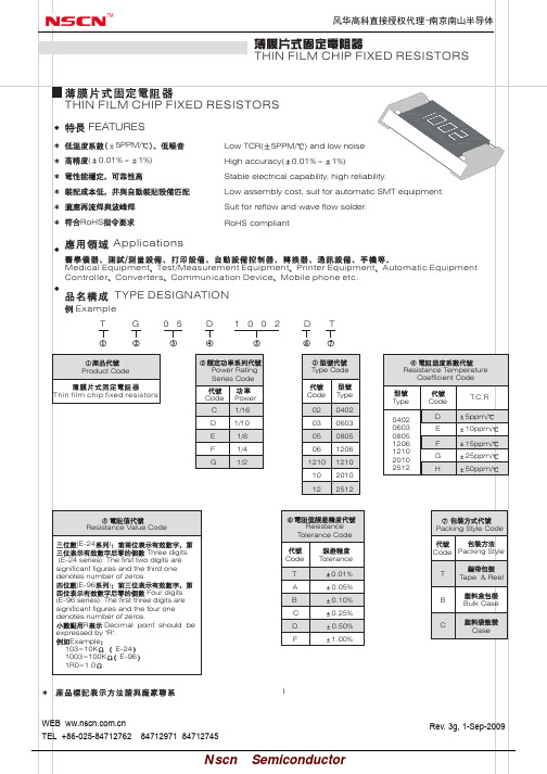
1/4W 150 300
1/2W 150 300
Special Ratings
Item
0402
0603
0805
1206
1210
2010
2512
Power Rating
1/16W
1/16W
1/10W
1/8W
1/4W
1/4W
1/2W
Max.Working
25
Voltage(V)
50
100
150
150
150
within specified T.C.R
MIL-STD-202F Method 304 +25/-55/+25/+125/+25
R
0.05%R+0.05
JIS-C-5202-7.2
R
0.5%R+0.05
2.5
5 :For thin film chip resistor with high power series: RCWV2.5 or Max Overload Voltage,
0.01% 0.05% 0.10%
0.10% 0.25% 0.50%
Operating Temperature Range
-55 ~+155
Characteristics
Item
Specifications
(GB/T 5729-2003) Test Method(GB/T 5729-2003)
T.C.R
unit:mm
a
b
0.20 0.10 0.30 0.20 0.30 0.20 0.40 0.20 0.50 0.20 0.60 0.20 0.60 0.20
ESD0P2RF-02LRH E6327中文资料(infineon)中文数据手册「EasyDatasheet - 矽搜」

ESD0P2RF系列
1.2
应用实例
• ESD防护护敏感RF信号线,蓝牙Class 2,自动抄表 • 射频天线防护护,前端模块,GPS,移动电视,FM收音机,UWB
1.3
产品描述
引脚1
引脚2
TSLP-2
引脚1
TSSLP-2
一)引脚配置
引脚2
图 1-1引脚配置和原理图
ESD0P2RF系列
特点
表 2-1
最大额定值
at TA = 25℃,除非另有说明
参数
符
值
Unit
Min.
Typ.
Max.
ESD空气/接触放电
1)
VESD
–
–
20
kV
峰值脉冲电流(
tp = 8/20 s)2) IPP
–
–
3
A
工作温度范围
TOP
-55
–
125
°C
储存温度
Tstg
-65
–
150
°C
1) VESD 根据IEC61000-4-2 2) IPP 根据IEC61000-4-5
最终数据手册
3
1.2版,2012年10月1日
芯片中文手册,看全文,戳
双向超低电容 ESD /瞬态防护护二极管
1
双向超低电容ESD /瞬态防护护
Diode
1.1
特征
• 射频信号线根据ESD /瞬态防护护:
– IEC61000-4-2(ESD):±20千伏(空气/触点)
– IEC61000-4-4 (EFT): 40 A(5/50 ns)
表 1-1
订购信息
Type ESD0P2RF-02LS
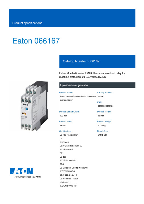
爱森·莫尔尔系列EMT6热敏过流保护器说明书
Eaton 066167Eaton Moeller® series EMT6 Thermistor overload relay for machine protection, 24-240V50/60HZ/DCEspecificaciones generalesEaton Moeller® series EMT6 Thermistor overload relay0661674015080661672103 mm 83 mm 23 mm 0.132 kg UL File No.: E29184 UL EN 55011CSA Class No.: 3211-03 IEC/EN 60947 CE UL 508IEC/EN 61000-4-2 CSAUL Category Control No.: NKCR IEC/EN 60947-8 CSA-C22.2 No. 14 CSA File No.: 12528 VDE 0660 IEC/EN 61000-4-3EMT6-DBProduct NameCatalog NumberEANProduct Length/Depth Product Height Product Width Product Weight CertificationsModel CodeScrew connectionManual or remote resettingNotifications of mains and faults via LED display Test function via separate buttonExternal reset possibleManual reset0 °C0 °C IP20As requiredIII3EMT6 thermistor overload relay for machine protectionFinger and back-of-hand proof, Protection against direct contact when actuated from front (EN 50274)6000 V AC4000 V AC250 V AC, Between the contacts and power supply, According to EN 61140250 V AC, Between the contacts, According to EN 6114010 g, Mechanical, according to IEC/EN 60068-2-27, Half-sinusoidal shock 10 msAC/DC-25 °C 60 °C 25 °C 45 °C 8 kV1 kV, Signal cable2 kV, Supply cableAccording to IEC/EN 61000-4-4 6 kVElectric connection typeFunctionsTemperature measuring range - min Temperature measuring range - max Degree of protectionMounting positionOvervoltage categoryPollution degreeProduct categoryProtectionRated impulse withstand voltage (Uimp) Safe isolationShock resistanceVoltage typeAmbient operating temperature - minAmbient operating temperature - maxAmbient operating temperature (enclosed) - min Ambient operating temperature (enclosed) - max Air dischargeBurst impulse Contact discharge Electromagnetic fields45 °C85 °CDamp heat, cyclic, to IEC 60068-2-30 Damp heat, constant, to IEC 60068-2-7810 V/m at 80 - 1000 MHz (according to IEC EN 61000-4-3) 3 V/m at 1.4 - 2 GHz (according to IEC EN 61000-4-3)1 V/m at 2.0 - 2.7 GHz (according to IEC EN 61000-4-3)10 V (according to IEC/EN 61000-4-6)Class B (EN 55011)According to IEC/EN 61000-4-5, power pulses (Surge), EMC 2 kV, symmetrical, power pulses (Surge), EMC4 kV, asymmetrical, power pulses (Surge), EMC1 x (0.5 - 2.5) mm², solid1 x (0.5 - 2.5) mm², flexible with ferrule2 x (0.5 - 1.5) mm², flexible with ferrule2 x (0.5 - 1.5) mm², solid20 - 14 AWG, solid or strandedM3.5, Terminal screw1 x 6 mm, Terminal screw, Standard screwdriver 2, Terminal screw, Pozidriv screwdriver1.2 Nm, Screw terminals 6 A0.85 - 1.1 V x Uₑ2 W at DC3.5 VA at AC24 V240 V24 V240 V24 V240 V400 V3 A at AC-14, 400 V (NC)3 A at AC-14, 380 V 400 V 415 V (NC) 3 A at AC-15, 220 V 230 V 240 V (NO)Ambient storage temperature - minAmbient storage temperature - max Climatic proofing Immunity to line-conducted interference Radio interference classSurge ratingTerminal capacityScrew size Screwdriver size Tightening torque Conventional thermal current ith of auxiliary contacts (1-pole, open)Pick-up voltagePower consumptionRated control supply voltage (Us) at AC, 50 Hz - minRated control supply voltage (Us) at AC, 50 Hz - maxRated control supply voltage (Us) at AC, 60 Hz - minRated control supply voltage (Us) at AC, 60 Hz - maxRated control supply voltage (Us) at DC - minRated control supply voltage (Us) at DC - maxRated insulation voltage (Ui)Rated operational current (Ie)3 A at AC-15, 220 V 230 V 240 V (NC) 3 A at AC-15, 220 V 230 V 240 V 3 A at AC-14, 300 V (NC) 1 A at AC-15, 300 V (NC) 3 A at AC-14, 300 V (NO)1 A at AC-15, 380 V 400 V 415 V (NO) 3 A at AC-14, 380 V 400 V 415 V (NO) 1 A at AC-15, 300 V (NO)1 A at AC-15, 380 V 400 V 415 V (NC)240 V1600 ΩMax. 6 A gG/gL, Fuse, Contacts3600 Ω600 V110 W0 W 0 W 0 A0.8 W eaton-tripping-emt6-thermistor-overload-relay-characteristic-curve-002.epseaton-tripping-emt6-thermistor-overload-relay-characteristic-curve.eps eaton-tripping-devices-relay-emt6-thermistor-overload-relay-dimensions.epseaton-tripping-thermistor-relay-emt6-dimensions.epseaton-tripping-devices-relay-emt6-thermistor-overload-relay-3d-drawing-002.eps DA-CE-ETN.EMT6-DB eaton-tripping-devices-emt6-thermistor-overload-relay-wiring-diagram.epsRated operational voltage (Ue) - max Reset resistance Short-circuit protection rating Trip resistance Voltage rating - max Number of contacts (change-over contacts)Number of contacts (normally closed contacts)Number of contacts (normally open contacts)Equipment heat dissipation, current-dependent PvidHeat dissipation capacity PdissHeat dissipation per pole, current-dependent PvidRated operational current for specified heat dissipation (In)Static heat dissipation, non-current-dependent Pvs Characteristic curveDibujoseCAD model Esquemas eléctricosEaton Corporation plc Eaton House30 Pembroke Road Dublin 4, Ireland © 2023 Eaton. All Rights Reserved. Eaton is a registered trademark.All other trademarks areproperty of their respectiveowners./socialmediaeaton-tripping-devices-auto-mode-emt6-thermistor-overload-relay-wiring-diagram.eps EMR6 - EMT6 - ETR4 brochure DA-DC-00003562.pdf DA-DC-00003971.pdf eaton-emt6-thermistor-motor-protection-relays-instruction-leaflet-il121016zu.pdf DA-CD-emt6_db DA-CS-emt6_dbFolletosInformes de certificación Instrucciones de montajemCAD model。
叠层片式压敏电阻器(PDF精品)

叠层片式压敏电阻器SDV3216A seriesAVL-06 seriesVC1206 seriesV-MLA1206 seriesSDV2012A series AVL-05 series VC0805 series V-MLA0805 series AVR-M2012 seriesSDV1608A series AVL-03 series VC0603 series V-MLA0603 series AVR-M1608 series SDV1005A series AVL-02 series VC0402 series V-MLA0402 series AVR-M1005 series Sunlord AMOTECH AVXLittlefuse TDK -普通信号线的静电防护及过电压保护叠层片式压敏电阻器SDV2012E series/VC08LC seriesV18MLE0805 seriesAVR-M2012 seriesSDV1608E series AVLC-03 series VC06LC series V18MLE0603 series AVR-M1608 series SDV1005E series AVLC-02 series VC04LC series V18MLE0402 series AVR-M1005 series Sunlord AMOTECH AVXLittlefuse TDK SDV1608H series SDV1608S seriesAVLC-03 seriesVC06AG seriesV0603MHS seriesAVRL16 seriesSDV1005H series SDV1005S series AVLC-02 series VC04AG series V0402MHS series AVRL10 series Sunlord AMOTECH AVXLittlefuse TDK -普通信号线的静电防护-高速信号线的静电防护MLVG06030R5MLVG04020R5INPAQ SDV1005H/S-0R5ADUC-02-0R5B72590D0050H160(CDS2C05HDMI1)/B72590D0050H260SDV1608H/S-0R5ADUC-03-0R5B72500D0050H160(CDS3C05HDMI1)AMOTECH Sunlord EPCOS-浪涌防护用-超高速信号线的静电防护叠层片式压敏电阻器SDVL3216Series SFI1206ML series VJ20M sereis V18AUMLA1206/V-MLA1206 series TVM3B series CT1206 series TVM6B seriesTVM5B series TVM4B series Thinking SDVL5650 seriesSFI2220ML seriesVJ15M seriesV18AUMLA2220 seriesCT2220 seriesSDVL4532 series SFI1812ML series VJ14M series V18AUMLA1812 seriesCT1812 series SDVL3225 series SFI1210ML series VJ13M series V18AUMLA1210 /V-MLA1210 series CT1210 series Sunlord SFI AVX Littelfuse Epcos叠层片式压敏电阻排SDVA2080VA series AVNC-05Q series ICVA21-4E series EZJZRV series SDVA2082VA seriesAVSC-05E series//SunlordAMOTECH ICTPanasonic SDVA2082R seriesAVRC-05Q seriesICVE21-4E series/SDVA1682R series /ICVE10-4E series /SunlordAMOTECHICTPanasonic SDVA2082FL seriesAVFC-05Q seriesICVF21-4E series/SDVA1682FL series /ICVF10-4E series /SunlordAMOTECHICTPanasonic -普通信号线的静电防护-过电压保护和EMI 抑制(R -C 复合电路结构)-过电压保护和EMI 抑制(L -C 复合电路结构)叠层片式聚合物静电抑制器-静电防护用PGB-0603PGB-0402LITTELFUSE PESD1005H series ASES12U02 series ULCE05 series MLSEP12A-0402PESD1608H seriesASES12U03 seriesULCE10 seriesMLSEP12A-0603Sunlord AMOTECH ICTSEMITEL。
STMicroelectronics STPS6M100SF数据手册说明书
STPS6M100SFFeatures•Low profile design – package height of 1.1 mm typ.•Wettable flanks for automatic visual inspection •Low forward voltage drop •Avalanche capability •ECOPACK ®2 compliantApplications•Switching diode •Notebook adapter •LED lighting•DC/DC converterDescriptionThis high voltage Schottky barrier rectifier has been optimized for use in highfrequency miniature DC/DC converters, reverse battery protection, battery chargers and adaptors.Packaged in PSMC (TO-277A), the STPS6M100SF provides a high level ofperformance in a compact and flat package which can withstand very high operating junction temperature.100 V power Schottky rectifierSTPS6M100SFDatasheetSTPS6M100SFCharacteristics 1CharacteristicsTable 1. Absolute ratings (limiting values at 25 °C, unless otherwise specified, anode terminals short-circuited)1.(dP tot/dT j) < (1/R th(j-a)) condition to avoid thermal runaway for a diode on its own heatsink.Table 2. Thermal resistance parametersFor more information, please refer to the following application note:•AN5088: Rectifiers thermal management, handling and mounting recommendationsTable 3. Static electrical characteristics (anode terminals short-circuited)1.Pulse test: t p = 5 ms, δ < 2%2.Pulse test: t p = 380 µs, δ < 2%To evaluate the conduction losses, use the following equation:P = 0.49 x I F(AV) + 0.0267 x I F2(RMS)For more information, please refer to the following application notes related to the power losses:•AN604: Calculation of conduction losses in a power rectifier•AN4021: Calculation of reverse losses in a power diodeSTPS6M100SFCharacteristics (curves) 1.1Characteristics (curves)Figure 7. Thermal resistance junction to ambient versus copper surface under tab (typical values, epoxyprinted board FR4, e Cu= 35 µm) (PSMC (TO-277A))020406080100120012345678910STPS6M100SFCharacteristics (curves)2Package informationIn order to meet environmental requirements, ST offers these devices in different grades of ECOPACK ®packages, depending on their level of environmental compliance. ECOPACK ® specifications, grade definitions and product status are available at: . ECOPACK ® is an ST trademark.2.1PSMC (TO-277A) package information•Epoxy meets UL94,V0•Cooling method : by conduction (C)Figure 8.PSMC (TO-277A) package outlineTable 4. PSMC (TO-277A) package mechanical dataSTPS6M100SFPackage informationFigure 9.PSMC (TO-277A) package footprint in mm (in inches)STPS6M100SFPSMC (TO-277A) package informationSTPS6M100SFOrdering information 3Ordering informationTable 5. Ordering informationSTPS6M100SFRevision historyTable 6. Document revision historySTPS6M100SFIMPORTANT NOTICE – PLEASE READ CAREFULLYSTMicroelectronics NV and its subsidiaries (“ST”) reserve the right to make changes, corrections, enhancements, modifications, and improvements to ST products and/or to this document at any time without notice. Purchasers should obtain the latest relevant information on ST products before placing orders. ST products are sold pursuant to ST’s terms and conditions of sale in place at the time of order acknowledgement.Purchasers are solely responsible for the choice, selection, and use of ST products and ST assumes no liability for application assistance or the design of Purchasers’ products.No license, express or implied, to any intellectual property right is granted by ST herein.Resale of ST products with provisions different from the information set forth herein shall void any warranty granted by ST for such product.ST and the ST logo are trademarks of ST. All other product or service names are the property of their respective owners.Information in this document supersedes and replaces information previously supplied in any prior versions of this document.© 2018 STMicroelectronics – All rights reservedSTPS6M100SF。
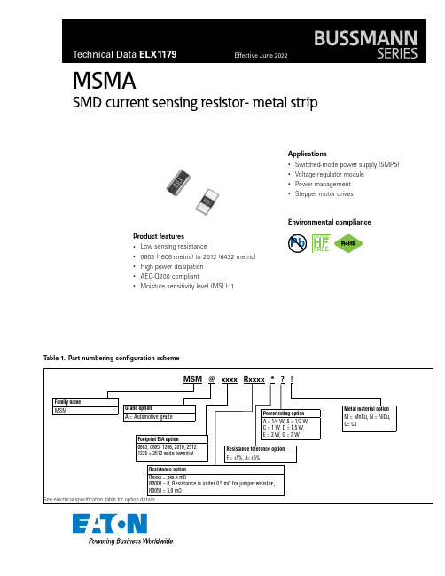
技术数据手册 ELX1179,有效日期:2022年6月,MSMA current sensing r
MSMASMD current sensing resistor- metal stripPb HALOGENHFFREET able 1. Part numbering configuration schemeMSM @ xxxx Rxxxx * ? !Family nameMSMGrade optionA = Automotive gradeFootprint EIA option0603, 0805, 1206, 2010, 2512 1225 = 2512 wide terminalResistance optionRxxxx = xxx.x mΩR0000 = 0, Resistance is under 0.5 mΩ for jumper resistor , R0050 = 5.0 mΩMetal material optionM = MnCu, N = NiCu, C= CuPower rating optionA = 1/4 W, S = 1/2 W,C = 1 W,D = 1.5 W,E = 2 W, G = 3 WResistance tolerance option F = ±1%, J= ±5%Product features• Low sensing resistance• 0603 (1608 metric) to 2512 (6432 metric)• High power dissipation • AEC-Q200 compliant•Moisture sensitivity level (MSL): 1Applications• Switched-mode power supply (SMPS)• Voltage regulator module • Power management •Stepper motor drivesEnvironmental complianceSee electrical specification table for option details2Technical Data ELX1179Effective June 2022MSMA SMD current sensing resistor- metal strip/electronicsMechanical parameters- Inches [mm]Recommended PCB layout- mmFamilySize codeLWCTFigureMSMA06030603[1608]0.063 ± 0.004[1.60 ± 0.10]0.031 ± 0.004[0.80 ± 0.10]0.016 ± 0.008[0.40 ± 0.20]0.012 ± 0.008[0.30 ± 0.20]A MSMA0805 R < 20805[2512]0.079 ± 0.008[2.0 ± 0.20]0.049 ± 0.008[1.25 ± 0.20]0.026 ± 0.012[0.65 ± 0.30]0.028 ± 0.008[0.70 ± 0.20]A MSMA0805 R ≥ 20805[2012]0.079 ± 0.008[2.0 ± 0.20]0.049 ± 0.008[1.25 ± 0.20]0.016 ± 0.012[0.40 ± 0.30]0.028 ± 0.008[0.70 ± 0.20]A MSMA1206 R = 11206[3216]0.126 ± 0.008[3.20 ± 0.20]0.063 ± 0.008[1.60 ± 0.20]0.043 ± 0.012[1.10 ± 0.30]0.030 ± 0.008[0.75 ± 0.20]A MSMA1206 R > 11206[3216]0.126 ± 0.008[3.20 ± 0.20]0.063 ± 0.008[1.60 ± 0.20]0.020 ± 0.012[0.50 ± 0.30]0.024 ± 0.008[0.60 ± 0.20]A MSMA2010 R ≤ 32010[5025]0.197 ± 0.008[5.0 ± 0.20]0.098 ± 0.008[2.50 ± 0.20]0.059 ± 0.012[1.50 ± 0.30]0.024 ± 0.008[0.60 ± 0.20]A MSMA2010 R > 32010[5025]0.197 ± 0.008[5.0 ± 0.20]0.098 ± 0.008[2.50 ± 0.20]0.024 ± 0.012[0.60 ± 0.30]0.024 ± 0.008[0.60 ± 0.20]A MSMA2512 R = 0.52512[6432]0.252 ± 0.008[6.40 ± 0.20]0.126 ± 0.008[3.20 ± 0.20]0.102 ± 0.008[2.60 ± 0.20]0.024 ± 0.008[0.60 ± 0.20]A MSMA2512 0.5 < R ≤ 32512[6432]0.252 ± 0.008[6.40 ± 0.20]0.126 ± 0.008[3.20 ± 0.20]0.087 ± 0.008[2.20 ± 0.20]0.024 ± 0.008[0.60 ± 0.20]A MSMA2512 3 < R ≤ 502512[6432]0.252 ± 0.008[6.40 ± 0.20]0.126 ± 0.008[3.20 ± 0.20]0.035 ± 0.008[0.90 ± 0.20]0.024 ± 0.008[0.60 ± 0.20]A MSMA2512 3W R ≤ 42512[6432]0.252 ± 0.008[6.40 ± 0.20]0.126 ± 0.008[3.20 ± 0.20]0.087 ± 0.008[2.2 ± 0.20]0.035 ± 0.008[0.90 ± 0.20]A MSMA2512 3W 4 < R ≤ 1002512[6432]0.252 ± 0.008[6.40 ± 0.20]0.126 ± 0.008[3.20 ± 0.20]0.035 ± 0.008[0.90 ± 0.20]0.035 ± 0.008[0.90 ± 0.20]A MSMA2512 R > 1002512[6432]0.252 ± 0.008[6.40 ± 0.20]0.126 ± 0.008[3.20 ± 0.20]0.035 ± 0.008[0.90 ± 0.20]0.035 ± 0.008[0.90 ± 0.20]A MSMA12251225[3264]0.126 ± 0.008[3.20 ± 0.20]0.252 ± 0.008[6.40 ± 0.20]0.020 ± 0.008[0.50 ± 0.20]0.035 ± 0.010[0.90 ± 0.25]BFigure AFigure BConstructionMetal Alloy PlateMatte Sn/Ni FamilyResistance (mΩ)A L BMSMA0603R = 0 2.10.70.7MSMA0805 1 ≤ R ≤ 2 1.40.7 1.152 ≤ R ≤ 25 1.4 1.2 1.15MSMA1206R = 1 1.8 1.0 2.31 ≤ R ≤ 50 1.8 1.6 1.7MSMA20101 ≤ R ≤ 3 3.4 2.0 3.54 ≤ R ≤ 50 3.4 3.5 1.5MSMA25120.5 ≤ R ≤ 3 4.0 1.3 3.13 W, R = 4 4.0 1.3 3.14 ≤ R 4.0 4.1 2.1MSMA12251 ≤ R ≤ 407.02.31.01. The copper foil thickness of PCB needs 3 oz. minimum2. PCB layout dimension tolerance is +/-0.1 mm.3. The resistance will change slightly after soldered; it is dependent on PCB pad size deign and it’s necessary to consider the effect of the resistance increase or decrease.Part markingFamilyMarkingMSMA0603No markingMSMA0805Resistance value is expressed by 3 digits.005 = 0.005 Ω or 5 mΩ010 = 0.010 Ω or 10 mΩWhite box = all values less than 2 mΩMSMA1206Resistance value is expressed by 2 or 4 digits.R01 = 0.001 Ω or 1 mΩ7R5m = 0.0075 Ω or 7.5 mΩR050 = 0.050 Ω or 50 mΩMSMA2010Resistance value is expressed by 4 digits.R001 = 0.001 Ω or 1 mΩR050 = 0.050 Ω or 50 mΩMSMA2512Resistance value is expressed by 4 digits.R50m = 0.0005 Ω or 0.5 mΩR001 = 0.001 Ω or 1 mΩ6R8m = 0.0068 Ω or 6.8 mΩR050 = 0.050 Ω or 50 mΩMSMA1225Resistance value is expressed by 3 or 4 digits.2R2m= .0022 Ω or 2.2 mΩ005 = 0.005 Ω or 5 mΩ010 = 0.010 Ω or 10 mΩ3Technical Data ELX1179Effective June 2022MSMASMD current sensing resistor- metal strip /electronics @= Enter grade option from table above (A=Automotive)Rxxxx = Enter resistance code option from table above xxxx= resistance code (R0000 = 0, Resistance is under 0.5mΩ for jumper resistor , R0050 = 5.0 mΩ)*= Enter resistance tolerance code option from table above (F= ±1%, J= ±5%)= Enter power rating code option from table above (A =1/4 W, S =1/2 W, C =1 W, D = 1.5 W, E = 2 W, G= 3 W)!=Enter metal material code option from tabel above (M = MnCu, N = NiCu, C= Cu)Electrical specificationsPart number SizeGrade optionResistance value mΩ (Part number code)Resistance tolerance (Part number code)Power rating (Part number code)Metal material (Part number code)TCR(ppm/°C)Operating temperatureMSM@0603Rxxxx*?!0603 (1608 metric)A 0 (0000)*±5% (J)1/4 W (A)Cu (C)3800-55 °C to +150 °C MSM@0805Rxxxx*?!0805 (2012 metric)A 1 (0010)±1% (F)1/2 W (S)MnCu (M)± 100-55 °C to +170 °C MSM@0805Rxxxx*?!0805 (2012 metric)A 1.5 (0015)±1% (F)1/2 W (S)MnCu (M)± 50-55 °C to +170 °C MSM@0805Rxxxx*?!0805 (2012 metric)A 2 (0020)±1% (F)1/2 W (S)MnCu (M)± 50-55 °C to +170 °C MSM@0805Rxxxx*?!0805 (2012 metric)A 3 (0030)±1% (F)1/2 W (S)MnCu (M)± 50-55 °C to +170 °C MSM@0805Rxxxx*?!0805 (2012 metric)A 4 (0040)±1% (F)1/2 W (S)MnCu (M)± 50-55 °C to +170 °C MSM@0805Rxxxx*?!0805 (2012 metric)A 5 (0050)±1% (F)1/2 W (S)MnCu (M)± 50-55 °C to +170 °C MSM@0805Rxxxx*?!0805 (2012 metric)A 6 (0060)±1% (F)1/2 W (S)MnCu (M)± 50-55 °C to +170 °C MSM@0805Rxxxx*?!0805 (2012 metric)A 8 (0080)±1% (F)1/2 W (S)MnCu (M)± 50-55 °C to +170 °C MSM@0805Rxxxx*?!0805 (2012 metric)A 9 (0090)±1% (F)1/2 W (S)MnCu (M)± 50-55 °C to +170 °C MSM@0805Rxxxx*?!0805 (2012 metric)A 10 (0100)±1% (F)1/2 W (S)MnCu (M)± 50-55 °C to +170 °C MSM@0805Rxxxx*?!0805 (2012 metric)A 15 (0150)±1% (F)1/2 W (S)MnCu (M)± 50-55 °C to +170 °C MSM@0805Rxxxx*?!0805 (2012 metric)A 20 (0200)±1% (F)1/2 W (S)MnCu (M)± 50-55 °C to +170 °C MSM@0805Rxxxx*?!0805 (2012 metric)A 25 (0250)±1% (F)1/2 W (S)MnCu (M)± 50-55 °C to +170 °C MSM@1206Rxxxx*?!1206 (3216 metric)A 1 (0010)±1% (F) 1 W (C)MnCu (M)± 50-55 °C to +170 °C MSM@1206Rxxxx*?!1206 (3216 metric)A 2 (0020)±1% (F) 1 W (C)MnCu (M)± 50-55 °C to +170 °C MSM@1206Rxxxx*?!1206 (3216 metric)A 3 (0030)±1% (F) 1 W (C)MnCu (M)± 50-55 °C to +170 °C MSM@1206Rxxxx*?!1206 (3216 metric)A 3.5 (0035)±1% (F) 1 W (C)MnCu (M)± 50-55 °C to +170 °C MSM@1206Rxxxx*?!1206 (3216 metric)A 4 (0040)±1% (F) 1 W (C)MnCu (M)± 50-55 °C to +170 °C MSM@1206Rxxxx*?!1206 (3216 metric)A 5 (0050)±1% (F) 1 W (C)MnCu (M)± 50-55 °C to +170 °C MSM@1206Rxxxx*?!1206 (3216 metric)A 6 (0060)±1% (F) 1 W (C)MnCu (M)± 50-55 °C to +170 °C MSM@1206Rxxxx*?!1206 (3216 metric)A 7 (0070)±1% (F) 1 W (C)MnCu (M)± 50-55 °C to +170 °C MSM@1206Rxxxx*?!1206 (3216 metric)A 7.5 (0075)±1% (F) 1 W (C)MnCu (M)± 50-55 °C to +170 °C MSM@1206Rxxxx*?!1206 (3216 metric)A 8 (0080)±1% (F) 1 W (C)MnCu (M)± 50-55 °C to +170 °C MSM@1206Rxxxx*?!1206 (3216 metric)A 9 (0090)±1% (F) 1 W (C)MnCu (M)± 50-55 °C to +170 °C MSM@1206Rxxxx*?!1206 (3216 metric)A 10 (0100)±1% (F) 1 W (C)MnCu (M)± 50-55 °C to +170 °C MSM@1206Rxxxx*?!1206 (3216 metric)A 12 (0120)±1% (F) 1 W (C)MnCu (M)± 50-55 °C to +170 °C MSM@1206Rxxxx*?!1206 (3216 metric)A 14 (0140)±1% (F) 1 W (C)MnCu (M)± 50-55 °C to +170 °C MSM@1206Rxxxx*?!1206 (3216 metric)A 15 (0150)±1% (F) 1 W (C)MnCu (M)± 50-55 °C to +170 °C MSM@1206Rxxxx*?!1206 (3216 metric)A 16 (0160)±1% (F) 1 W (C)MnCu (M)± 50-55 °C to +170 °C MSM@1206Rxxxx*?!1206 (3216 metric)A 18 (0180)±1% (F) 1 W (C)MnCu (M)± 50-55 °C to +170 °C MSM@1206Rxxxx*?!1206 (3216 metric)A 20 (0200)±1% (F) 1 W (C)MnCu (M)± 50-55 °C to +170 °C MSM@1206Rxxxx*?!1206 (3216 metric)A 22 (0220)±1% (F) 1 W (C)MnCu (M)± 50-55 °C to +170 °C MSM@1206Rxxxx*?!1206 (3216 metric)A 25 (0250)±1% (F) 1 W (C)MnCu (M)± 50-55 °C to +170 °C MSM@1206Rxxxx*?!1206 (3216 metric)A 30 (0300)±1% (F) 1 W (C)MnCu (M)± 50-55 °C to +170 °C MSM@1206Rxxxx*?!1206 (3216 metric)A 40 (0400)±1% (F) 1 W (C)MnCu (M)± 50-55 °C to +170 °C MSM@1206Rxxxx*?!1206 (3216 metric)A50 (0500)±1% (F)1 W (C)MnCu (M)± 50-55 °C to +170 °C4Technical Data ELX1179Effective June 2022MSMA SMD current sensing resistor- metal strip/electronicsElectrical specificationsPart number SizeGrade option Resistance value mΩ (Part number code)Resistance tolerance (Part number code)Power rating (Part number code)Metal material (Part number code)TCR(ppm/°C)Operating temperatureMSM@2010Rxxxx*?!2010 (5025 metric)A 1 (0010)±1% (F) 1.5 W (D)MnCu (M)± 50-55 °C to +170 °C MSM@2010Rxxxx*?!2010 (5025 metric)A 2 (0020)±1% (F) 1.5 W (D)MnCu (M)± 50-55 °C to +170 °C MSM@2010Rxxxx*?!2010 (5025 metric)A 14 (0140)±1% (F) 1.5 W (D)MnCu (M)± 50-55 °C to +170 °C MSM@2010Rxxxx*?!2010 (5025 metric)A 30 (0300)±1% (F) 1.5 W (D)MnCu (M)± 50-55 °C to +170 °C MSM@2010Rxxxx*?!2010 (5025 metric)A 5 (0050)±1% (F) 1.5 W (D)NiCu (N)± 50-55 °C to +170 °C MSM@2010Rxxxx*?!2010 (5025 metric)A 6 (0060)±1% (F) 1.5 W (D)NiCu (N)± 50-55 °C to +170 °C MSM@2010Rxxxx*?!2010 (5025 metric)A 10 (0100)±1% (F) 1.5 W (D)NiCu (N)± 50-55 °C to +170 °C MSM@2010Rxxxx*?!2010 (5025 metric)A 15 (0150)±1% (F) 1.5 W (D)NiCu (N)± 50-55 °C to +170 °C MSM@2010Rxxxx*?!2010 (5025 metric)A 20 (0200)±1% (F) 1.5 W (D)NiCu (N)± 50-55 °C to +170 °C MSM@2010Rxxxx*?!2010 (5025 metric)A 50 (0500)±1% (F) 1.5 W (D)NiCu (N)± 50-55 °C to +170 °C MSM@2512Rxxxx*?!2512 (6432 metric)A 1 (0010)±1% (F) 2 W (E)NiCu (N)± 50-55 °C to +170 °C MSM@2512Rxxxx*?!2512 (6432 metric)A 2 (0020)±1% (F) 2 W (E)NiCu (N)± 50-55 °C to +170 °C MSM@2512Rxxxx*?!2512 (6432 metric)A 3 (0030)±1% (F) 2 W (E)NiCu (N)± 50-55 °C to +170 °C MSM@2512Rxxxx*?!2512 (6432 metric)A 3.5 (0035)±1% (F) 2 W (E)NiCu (N)± 50-55 °C to +170 °C MSM@2512Rxxxx*?!2512 (6432 metric)A 4 (0040)±1% (F) 2 W (E)NiCu (N)± 50-55 °C to +170 °C MSM@2512Rxxxx*?!2512 (6432 metric)A 5 (0050)±1% (F) 2 W (E)NiCu (N)± 50-55 °C to +170 °C MSM@2512Rxxxx*?!2512 (6432 metric)A 6 (0060)±1% (F) 2 W (E)NiCu (N)± 50-55 °C to +170 °C MSM@2512Rxxxx*?!2512 (6432 metric)A 7 (0070)±1% (F) 2 W (E)NiCu (N)± 50-55 °C to +170 °C MSM@2512Rxxxx*?!2512 (6432 metric)A 8 (0080)±1% (F) 2 W (E)NiCu (N)± 50-55 °C to +170 °C MSM@2512Rxxxx*?!2512 (6432 metric)A 9 (0090)±1% (F) 2 W (E)NiCu (N)± 50-55 °C to +170 °C MSM@2512Rxxxx*?!2512 (6432 metric)A 10 (0100)±1% (F) 2 W (E)NiCu (N)± 50-55 °C to +170 °C MSM@2512Rxxxx*?!2512 (6432 metric)A 11 (0110)±1% (F) 1 W (C)NiCu (N)± 50-55 °C to +170 °C MSM@2512Rxxxx*?!2512 (6432 metric)A 15 (0150)±1% (F) 1 W (C)NiCu (N)± 50-55 °C to +170 °C MSM@2512Rxxxx*?!2512 (6432 metric)A 16 (0160)±1% (F) 1 W (C)NiCu (N)± 50-55 °C to +170 °C MSM@2512Rxxxx*?!2512 (6432 metric)A 18 (0180)±1% (F) 1 W (C)NiCu (N)± 50-55 °C to +170 °C MSM@2512Rxxxx*?!2512 (6432 metric)A 20 (0200)±1% (F) 1 W (C)NiCu (N)± 50-55 °C to +170 °C MSM@2512Rxxxx*?!2512 (6432 metric)A 25 (0250)±1% (F) 1 W (C)NiCu (N)± 50-55 °C to +170 °C MSM@2512Rxxxx*?!2512 (6432 metric)A 30 (0300)±1% (F) 1 W (C)NiCu (N)± 50-55 °C to +170 °C MSM@2512Rxxxx*?!2512 (6432 metric)A 33 (0330)±1% (F) 1 W (C)NiCu (N)± 50-55 °C to +170 °C MSM@2512Rxxxx*?!2512 (6432 metric)A 35 (0350)±1% (F) 1 W (C)NiCu (N)± 50-55 °C to +170 °C MSM@2512Rxxxx*?!2512 (6432 metric)A 40 (0400)±1% (F) 1 W (C)NiCu (N)± 50-55 °C to +170 °C MSM@2512Rxxxx*?!2512 (6432 metric)A 50 (0500)±1% (F) 1 W (C)NiCu (N)± 50-55 °C to +170 °C MSM@2512Rxxxx*?!2512 (6432 metric)A 0.5 (0005)±1% (F) 3 W (G)MnCu (M)± 50-55 °C to +170 °C MSM@2512Rxxxx*?!2512 (6432 metric)A 1 (0010)±1% (F) 3 W (G)MnCu (M)± 50-55 °C to +170 °C MSM@2512Rxxxx*?!2512 (6432 metric)A 1.1 (0011)±1% (F) 3 W (G)MnCu (M)± 50-55 °C to +170 °C MSM@2512Rxxxx*?!2512 (6432 metric)A 1.5 (0015)±1% (F) 3 W (G)MnCu (M)± 50-55 °C to +170 °C MSM@2512Rxxxx*?!2512 (6432 metric)A 2 (0020)±1% (F) 3 W (G)MnCu (M)± 50-55 °C to +170 °C MSM@2512Rxxxx*?!2512 (6432 metric)A 3 (0030)±1% (F) 3 W (G)MnCu (M)± 50-55 °C to +170 °C MSM@2512Rxxxx*?!2512 (6432 metric)A 4 (0040)±1% (F) 3 W (G)MnCu (M)± 50-55 °C to +170 °C MSM@2512Rxxxx*?!2512 (6432 metric)A 5 (0050)±1% (F) 3 W (G)MnCu (M)± 50-55 °C to +170 °C MSM@2512Rxxxx*?!2512 (6432 metric)A 6 (0060)±1% (F) 3 W (G)MnCu (M)± 50-55 °C to +170 °C MSM@2512Rxxxx*?!2512 (6432 metric)A7 (0070)±1% (F)3 W (G)MnCu (M)± 50-55 °C to +170 °C@= Enter grade option from table above (A=Automotive)Rxxxx = Enter resistance code option from table above xxxx= resistance code (R0000 = 0, Resistance is under 0.5mΩ for jumper resistor , R0050 = 5.0 mΩ)*= Enter resistance tolerance code option from table above (F= ±1%, J= ±5%)= Enter power rating code option from table above (A =1/4 W, S =1/2 W, C =1 W, D = 1.5 W, E = 2 W, G= 3 W)!=Enter metal material code option from tabel above (M = MnCu, N = NiCu, C= Cu)5Technical Data ELX1179Effective June 2022MSMASMD current sensing resistor- metal strip/electronics Electrical specificationsPart number SizeGrade optionResistance value mΩ (Part number code)Resistance tolerance (Part number code)Power rating (Part number code)Metal material (Part number code)TCR(ppm/°C)Operating temperatureMSM@2512Rxxxx*?!2512 (6432 metric)A 8 (0080)±1% (F) 3 W (G)MnCu (M)± 50-55 °C to +170 °C MSM@2512Rxxxx*?!2512 (6432 metric)A 9 (0090)±1% (F) 3 W (G)MnCu (M)± 50-55 °C to +170 °C MSM@2512Rxxxx*?!2512 (6432 metric)A 10 (0100)±1% (F) 3 W (G)MnCu (M)± 50-55 °C to +170 °C MSM@2512Rxxxx*?!2512 (6432 metric)A 12 (0120)±1% (F) 3 W (G)MnCu (M)± 50-55 °C to +170 °C MSM@2512Rxxxx*?!2512 (6432 metric)A 15 (0150)±1% (F) 3 W (G)MnCu (M)± 50-55 °C to +170 °C MSM@2512Rxxxx*?!2512 (6432 metric)A 16 (0160)±1% (F) 3 W (G)MnCu (M)± 50-55 °C to +170 °C MSM@2512Rxxxx*?!2512 (6432 metric)A 20 (0200)±1% (F) 3 W (G)MnCu (M)± 50-55 °C to +170 °C MSM@2512Rxxxx*?!2512 (6432 metric)A 25 (0250)±1% (F) 3 W (G)MnCu (M)± 50-55 °C to +170 °C MSM@2512Rxxxx*?!2512 (6432 metric)A 27 (0270)±1% (F) 3 W (G)MnCu (M)± 50-55 °C to +170 °C MSM@2512Rxxxx*?!2512 (6432 metric)A 30 (0300)±1% (F) 3 W (G)MnCu (M)± 50-55 °C to +170 °C MSM@2512Rxxxx*?!2512 (6432 metric)A 33 (0330)±1% (F) 3 W (G)MnCu (M)± 50-55 °C to +170 °C MSM@2512Rxxxx*?!2512 (6432 metric)A 40 (0400)±1% (F) 3 W (G)MnCu (M)± 50-55 °C to +170 °C MSM@2512Rxxxx*?!2512 (6432 metric)A 42 (0420)±1% (F) 3 W (G)MnCu (M)± 50-55 °C to +170 °C MSM@2512Rxxxx*?!2512 (6432 metric)A 45 (0450)±1% (F) 3 W (G)MnCu (M)± 50-55 °C to +170 °C MSM@2512Rxxxx*?!2512 (6432 metric)A 48 (0480)±1% (F) 3 W (G)MnCu (M)± 50-55 °C to +170 °C MSM@2512Rxxxx*?!2512 (6432 metric)A 50 (0500)±1% (F) 3 W (G)MnCu (M)± 50-55 °C to +170 °C MSM@2512Rxxxx*?!2512 (6432 metric)A 60 (0600)±1% (F) 3 W (G)MnCu (M)± 50-55 °C to +170 °C MSM@2512Rxxxx*?!2512 (6432 metric)A 70 (0700)±1% (F) 3 W (G)MnCu (M)± 50-55 °C to +170 °C MSM@2512Rxxxx*?!2512 (6432 metric)A 3 (0030)±1% (F) 3 W (G)NiCu (N)± 50-55 °C to +170 °C MSM@2512Rxxxx*?!2512 (6432 metric)A 4 (0040)±1% (F) 3 W (G)NiCu (N)± 50-55 °C to +170 °C MSM@2512Rxxxx*?!2512 (6432 metric)A 10 (0100)±1% (F) 3 W (G)NiCu (N)± 50-55 °C to +170 °C MSM@2512Rxxxx*?!2512 (6432 metric)A 11 (0110)±1% (F) 3 W (G)NiCu (N)± 50-55 °C to +170 °C MSM@2512Rxxxx*?!2512 (6432 metric)A 12 (0120)±1% (F) 3 W (G)NiCu (N)± 50-55 °C to +170 °C MSM@2512Rxxxx*?!2512 (6432 metric)A 13 (0130)±1% (F) 3 W (G)NiCu (N)± 50-55 °C to +170 °C MSM@2512Rxxxx*?!2512 (6432 metric)A 15 (0150)±1% (F) 3 W (G)NiCu (N)± 50-55 °C to +170 °C MSM@2512Rxxxx*?!2512 (6432 metric)A 18 (0180)±1% (F) 3 W (G)NiCu (N)± 50-55 °C to +170 °C MSM@2512Rxxxx*?!2512 (6432 metric)A 20 (0200)±1% (F) 3 W (G)NiCu (N)± 50-55 °C to +170 °C MSM@2512Rxxxx*?!2512 (6432 metric)A 22 (0220)±1% (F) 3 W (G)NiCu (N)± 50-55 °C to +170 °C MSM@2512Rxxxx*?!2512 (6432 metric)A 25 (0250)±1% (F) 3 W (G)NiCu (N)± 50-55 °C to +170 °C MSM@2512Rxxxx*?!2512 (6432 metric)A 30 (0300)±1% (F) 3 W (G)NiCu (N)± 50-55 °C to +170 °C MSM@2512Rxxxx*?!2512 (6432 metric)A 33 (0330)±1% (F) 3 W (G)NiCu (N)± 50-55 °C to +170 °C MSM@2512Rxxxx*?!2512 (6432 metric)A 35 (0350)±1% (F) 3 W (G)NiCu (N)± 50-55 °C to +170 °C MSM@2512Rxxxx*?!2512 (6432 metric)A 39 (0390)±1% (F) 3 W (G)NiCu (N)± 50-55 °C to +170 °C MSM@2512Rxxxx*?!2512 (6432 metric)A 40 (0400)±1% (F) 3 W (G)NiCu (N)± 50-55 °C to +170 °C MSM@2512Rxxxx*?!2512 (6432 metric)A 42 (0420)±1% (F) 3 W (G)NiCu (N)± 50-55 °C to +170 °C MSM@2512Rxxxx*?!2512 (6432 metric)A 45 (0450)±1% (F) 3 W (G)NiCu (N)± 50-55 °C to +170 °C MSM@2512Rxxxx*?!2512 (6432 metric)A 47 (0470)±1% (F) 3 W (G)NiCu (N)± 50-55 °C to +170 °C MSM@2512Rxxxx*?!2512 (6432 metric)A 48 (0480)±1% (F) 3 W (G)NiCu (N)± 50-55 °C to +170 °C MSM@2512Rxxxx*?!2512 (6432 metric)A 50 (0500)±1% (F) 3 W (G)NiCu (N)± 50-55 °C to +170 °C MSM@2512Rxxxx*?!2512 (6432 metric)A 56 (0560)±1% (F) 3 W (G)NiCu (N)± 50-55 °C to +170 °C MSM@2512Rxxxx*?!2512 (6432 metric)A 57 (0570)±1% (F) 3 W (G)NiCu (N)± 50-55 °C to +170 °C MSM@2512Rxxxx*?!2512 (6432 metric)A60 (0600)±1% (F)3 W (G)NiCu (N)± 50-55 °C to +170 °C@= Enter grade option from table above (A=Automotive)Rxxxx = Enter resistance code option from table above xxxx= resistance code (R0000 = 0, Resistance is under 0.5mΩ for jumper resistor , R0050 = 5.0 mΩ)*= Enter resistance tolerance code option from table above (F= ±1%, J= ±5%)= Enter power rating code option from table above (A =1/4 W, S =1/2 W, C =1 W, D = 1.5 W, E = 2 W, G= 3 W)!=Enter metal material code option from tabel above (M = MnCu, N = NiCu, C= Cu)6Technical Data ELX1179Effective June 2022MSMA SMD current sensing resistor- metal strip/electronicsElectrical specificationsPart number SizeGrade optionResistance value mΩ (Part number code)Resistance tolerance (Part number code)Power rating (Part number code)Metal material (Part number code)TCR(ppm/°C)Operating temperatureMSM@2512Rxxxx*?!2512 (6432 metric)A 65 (0650)±1% (F) 3 W (G)NiCu (N)± 50-55 °C to +170 °C MSM@2512Rxxxx*?!2512 (6432 metric)A 68 (0680)±1% (F) 3 W (G)NiCu (N)± 50-55 °C to +170 °C MSM@2512Rxxxx*?!2512 (6432 metric)A 70 (0700)±1% (F) 3 W (G)NiCu (N)± 50-55 °C to +170 °C MSM@2512Rxxxx*?!2512 (6432 metric)A 75 (0750)±1% (F) 3 W (G)NiCu (N)± 50-55 °C to +170 °C MSM@2512Rxxxx*?!2512 (6432 metric)A 80 (0800)±1% (F) 3 W (G)NiCu (N)± 50-55 °C to +170 °C MSM@2512Rxxxx*?!2512 (6432 metric)A 85 (0850)±1% (F) 3 W (G)NiCu (N)± 50-55 °C to +170 °C MSM@2512Rxxxx*?!2512 (6432 metric)A 90 (0900)±1% (F) 3 W (G)NiCu (N)± 50-55 °C to +170 °C MSM@2512Rxxxx*?!2512 (6432 metric)A 100 (1000)±1% (F) 3 W (G)NiCu (N)± 50-55 °C to +170 °C MSM@2512Rxxxx*?!2512 (6432 metric)A 120 (1200)±1% (F) 2 W (E)NiCu (N)± 50-55 °C to +170 °C MSM@2512Rxxxx*?!2512 (6432 metric)A 130 (1300)±1% (F) 2 W (E)NiCu (N)± 50-55 °C to +170 °C MSM@2512Rxxxx*?!2512 (6432 metric)A 140 (1400)±1% (F) 2 W (E)NiCu (N)± 50-55 °C to +170 °C MSM@2512Rxxxx*?!2512 (6432 metric)A 150 (1500)±1% (F) 2 W (E)NiCu (N)± 50-55 °C to +170 °C MSM@2512Rxxxx*?!2512 (6432 metric)A 170 (1700)±1% (F) 2 W (E)NiCu (N)± 50-55 °C to +170 °C MSM@2512Rxxxx*?!2512 (6432 metric)A 175 (1750)±1% (F) 2 W (E)NiCu (N)± 50-55 °C to +170 °C MSM@2512Rxxxx*?!2512 (6432 metric)A 180 (1800)±1% (F) 2 W (E)NiCu (N)± 50-55 °C to +170 °C MSM@2512Rxxxx*?!2512 (6432 metric)A 200 (2000)±1% (F) 2 W (E)NiCu (N)± 50-55 °C to +170 °C MSM@2512Rxxxx*?!2512 (6432 metric)A 220 (2200)±1% (F) 2 W (E)NiCu (N)± 50-55 °C to +170 °C MSM@2512Rxxxx*?!2512 (6432 metric)A 240 (2400)±1% (F) 2 W (E)NiCu (N)± 50-55 °C to +170 °C MSM@2512Rxxxx*?!2512 (6432 metric)A 250 (2500)±1% (F) 2 W (E)NiCu (N)± 50-55 °C to +170 °C MSM@2512Rxxxx*?!2512 (6432 metric)A 270 (2700)±1% (F) 2 W (E)NiCu (N)± 50-55 °C to +170 °C MSM@2512Rxxxx*?!2512 (6432 metric)A 300 (3000)±1% (F) 2 W (E)NiCu (N)± 50-55 °C to +170 °C MSM@2512Rxxxx*?!2512 (6432 metric)A 330 (3300)±1% (F) 2 W (E)NiCu (N)± 50-55 °C to +170 °C MSM@2512Rxxxx*?!2512 (6432 metric)A 390 (3900)±1% (F) 2 W (E)NiCu (N)± 50-55 °C to +170 °C MSM@2512Rxxxx*?!2512 (6432 metric)A 400 (4000)±1% (F) 2 W (E)NiCu (N)± 50-55 °C to +170 °C MSM@2512Rxxxx*?!2512 (6432 metric)A 500 (5000)±1% (F) 2 W (E)NiCu (N)± 50-55 °C to +170 °C MSM@2512Rxxxx*?!2512 (6432 metric)A 510 (5100)±1% (F) 2 W (E)NiCu (N)± 50-55 °C to +170 °C MSM@2512Rxxxx*?!2512 (6432 metric)A 560 (5600)±1% (F) 2 W (E)NiCu (N)± 50-55 °C to +170 °C MSM@2512Rxxxx*?!2512 (6432 metric)A 680 (6800)±1% (F) 2 W (E)NiCu (N)± 50-55 °C to +170 °C MSM@1225Rxxxx*?!1225 (3264 metric)A 1 (0010)±1% (F) 3 W (G)MnCu (M)± 75-55 °C to +170 °C MSM@1225Rxxxx*?!1225 (3264 metric)A 2 (0020)±1% (F) 3 W (G)MnCu (M)± 50-55 °C to +170 °C MSM@1225Rxxxx*?!1225 (3264 metric)A 2.2 (0022)±1% (F) 3 W (G)MnCu (M)± 50-55 °C to +170 °C MSM@1225Rxxxx*?!1225 (3264 metric)A 3 (0030)±1% (F) 3 W (G)MnCu (M)± 50-55 °C to +170 °C MSM@1225Rxxxx*?!1225 (3264 metric)A 4 (0040)±1% (F) 3 W (G)MnCu (M)± 50-55 °C to +170 °C MSM@1225Rxxxx*?!1225 (3264 metric)A 5 (0050)±1% (F) 3 W (G)MnCu (M)± 50-55 °C to +170 °C MSM@1225Rxxxx*?!1225 (3264 metric)A 6 (0060)±1% (F) 3 W (G)MnCu (M)± 50-55 °C to +170 °C MSM@1225Rxxxx*?!1225 (3264 metric)A 7 (0070)±1% (F) 3 W (G)MnCu (M)± 50-55 °C to +170 °C MSM@1225Rxxxx*?!1225 (3264 metric)A 8 (0080)±1% (F) 3 W (G)MnCu (M)± 50-55 °C to +170 °C MSM@1225Rxxxx*?!1225 (3264 metric)A 9 (0090)±1% (F) 3 W (G)MnCu (M)± 50-55 °C to +170 °C MSM@1225Rxxxx*?!1225 (3264 metric)A 10 (0100)±1% (F) 3 W (G)MnCu (M)± 50-55 °C to +170 °C MSM@1225Rxxxx*?!1225 (3264 metric)A12 (0120)±1% (F)3 W (G)MnCu (M)± 50-55 °C to +170 °C@= Enter grade option from table above (A=Automotive)Rxxxx = Enter resistance code option from table above xxxx= resistance code (R0000 = 0, Resistance is under 0.5mΩ for jumper resistor , R0050 = 5.0 mΩ)*= Enter resistance tolerance code option from table above (F= ±1%, J= ±5%)= Enter power rating code option from table above (A =1/4 W, S =1/2 W, C =1 W, D = 1.5 W, E = 2 W, G= 3 W)!=Enter metal material code option from tabel above (M = MnCu, N = NiCu, C= Cu)7Technical Data ELX1179Effective June 2022MSMASMD current sensing resistor- metal strip /electronics Electrical specificationsPart number SizeGrade optionResistance value mΩ (Part number code)Resistance tolerance (Part number code)Power rating (Part number code)Metal material (Part number code)TCR(ppm/°C)Operating temperatureMSM@1225Rxxxx*?!1225 (3264 metric)A 15 (0150)±1% (F) 3 W (G)MnCu (M)± 50-55 °C to +170 °C MSM@1225Rxxxx*?!1225 (3264 metric)A 20 (0200)±1% (F) 3 W (G)MnCu (M)± 50-55 °C to +170 °C MSM@1225Rxxxx*?!1225 (3264 metric)A 25 (0250)±1% (F) 3 W (G)MnCu (M)± 50-55 °C to +170 °C MSM@1225Rxxxx*?!1225 (3264 metric)A 30 (0300)±1% (F) 3 W (G)MnCu (M)± 50-55 °C to +170 °C MSM@1225Rxxxx*?!1225 (3264 metric)A 33 (0330)±1% (F) 3 W (G)MnCu (M)± 50-55 °C to +170 °C MSM@1225Rxxxx*?!1225 (3264 metric)A40 (0400)±1% (F)3 W (G)MnCu (M)± 50-55 °C to +170 °C@= Enter grade option from table above (A=Automotive)Rxxxx = Enter resistance code option from table above xxxx= resistance code (R0000 = 0, Resistance is under 0.5mΩ for jumper resistor , R0050 = 5.0 mΩ)*= Enter resistance tolerance code option from table above (F= ±1%, J= ±5%)= Enter power rating code option from table above (A =1/4 W, S =1/2 W, C =1 W, D = 1.5 W, E = 2 W, G= 3 W)!=Enter metal material code option from tabel above (M = MnCu, N = NiCu, C= Cu)。
ST EMIF06-10006F2 数据手册
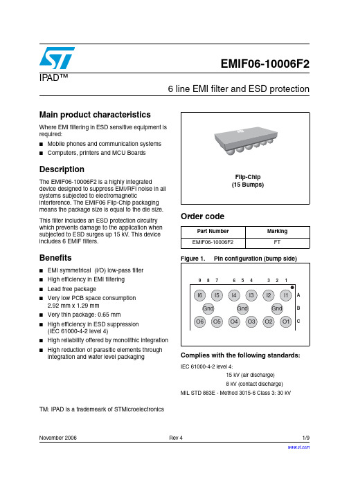
November 2006 Rev 41/9EMIF06-10006F2IP AD™6 line EMI filter and ESD protectionMain product characteristicsWhere EMI filtering in ESD sensitive equipment is required:■Mobile phones and communication systems ■Computers, printers and MCU BoardsDescriptionThe EMIF06-10006F2 is a highly integrateddevice designed to suppress EMI/RFI noise in all systems subjected to electromagneticinterference. The EMIF06 Flip-Chip packaging means the package size is equal to the die size.This filter includes an ESD protection circuitry which prevents damage to the application when subjected to ESD surges up 15 kV . This device includes 6 EMIF filters.Benefits■EMI symmetrical (I/O) low-pass filter ■High efficiency in EMI filtering ■Lead free package■Very low PCB space consumption 2.92 mm x 1.29 mm ■Very thin package: 0.65 mm ■High efficiency in ESD suppression (IEC 61000-4-2 level 4)■High reliability offered by monolithic integration ■High reduction of parasitic elements through integration and wafer level packagingTM: IPAD is a trademeark of STMicroelectronicsOrder codeComplies with the following standards:Part Number Marking EMIF06-10006F2FTIEC 61000-4-2 level 4:15 kV (air discharge)8 kV (contact discharge)MIL STD 883E - Method 3015-6 Class 3: 30 kVCharacteristics EMIF06-10006F22/91 CharacteristicsTable 1.Absolute Ratings (limiting values)Symbol Parameter and test conditionsValue Unit P R DC power per resistance 0.1W P T T otal DC power per package 0.6W T j Maximum junction temperature 125° C T op Operating temperature range - 40 to + 85° C T stgStorage temperature range125° CSymbol Test conditionsMin.Typ.Max.Unit V BR I R = 1 mA5.579 V I RM V RM = 3.3 V per line 500 nA R I/O I = 10 mA80 100 120 Ω C lineV R = 2.5 V , F = 1 MHz, 30 mV (on filter cells)506070pFEMIF06-10006F2Characteristics3/9Figure 3.S21 (db) attenuation measurementsFigure 4.Analog crosstalk measurementsFigure 5.Digital crosstalk measurements Figure 6.ESD response to IEC 61000-4-2(+15 kV air discharge) on one imput (V in ) and one output (V out )Figure 7.ESD response to IEC 61000-4-2 (–15 kV air discharge) on one imput Figure 8.Line capacitance versus applied voltage for filterCharacteristics EMIF06-10006F24/9Figure 10.Figure 10: Aplac parametersaplacvar RSaplacvar Czaplacvar Lbumpaplacvar Rbumpaplacvar Cbumpaplacvar Rsubaplacvar Rgndaplacvar Lgndaplacvar Cgnd10041 pF50 pH20 m1.2 pF100 m100 m100 pH0.15 pFΩEMIF06-10006F2Ordering Information Scheme 2 Ordering Information Scheme5/9Package information EMIF06-10006F26/93 Package informationEMIF06-10006F2Package informationIn order to meet environmental requirements, ST offers these devices in ECOPACK®packages. These packages have a lead-free second level interconnect. The category ofsecond level interconnect is marked on the package and on the inner box label, incompliance with JEDEC Standard JESD97. The maximum ratings related to solderingconditions are also marked on the inner box label. ECOPACK is an ST trademark.ECOPACK specifications are available at: .Note:Note: More packing information is available in the application notes:AN1235: “Flip-Chip: Package description and recommendations for use”AN1751: "EMI Filters: Recommendations and measurements"7/9Ordering Information EMIF06-10006F28/94 Ordering Information5 Revision H istoryOrdering code Marking Package Weight Base qty Delivery mode EMIF06-10006F2FTFlip-Chip5.4 mg5000T ape and reel 7”Date RevisionDescription of ChangesSep-20041First issue19-Nov-20042Figure 2 on page 2:Basic cell configuration corrected for I/O5 and I/O6.11-Apr-20063Reformated to current standard. Marking corrected in ordering information.17-Nov-20064Ordering code in ordering information corrected.EMIF06-10006F2Please Read Carefully:Information in this document is provided solely in connection with ST products. STMicroelectronics NV and its subsidiaries (“ST”) reserve the right to make changes, corrections, modifications or improvements, to this document, and the products and services described herein at any time, without notice.All ST products are sold pursuant to ST’s terms and conditions of sale.Purchasers are solely responsible for the choice, selection and use of the ST products and services described herein, and ST assumes no liability whatsoever relating to the choice, selection or use of the ST products and services described herein.No license, express or implied, by estoppel or otherwise, to any intellectual property rights is granted under this document. If any part of this document refers to any third party products or services it shall not be deemed a license grant by ST for the use of such third party products or services, or any intellectual property contained therein or considered as a warranty covering the use in any manner whatsoever of such third party products or services or any intellectual property contained therein.UNLESS OTH ERWISE SET FORTH IN ST’S TERMS AND CONDITIONS OF SALE ST DISCLAIMS ANY EXPRESS OR IMPLIED WARRANTY WITH RESPECT TO TH E USE AND/OR SALE OF ST PRODUCTS INCLUDING WITH OUT LIMITATION IMPLIED WARRANTIES OF MERCHANTABILITY, FITNESS FOR A PARTICULAR PURPOSE (AND THEIR EQUIVALENTS UNDER THE LAWS OF ANY JURISDICTION), OR INFRINGEMENT OF ANY PATENT, COPYRIGHT OR OTHER INTELLECTUAL PROPERTY RIGHT. UNLESS EXPRESSLY APPROVED IN WRITING BY AN AUTH ORIZED ST REPRESENTATIVE, ST PRODUCTS ARE NOT RECOMMENDED, AUTHORIZED OR WARRANTED FOR USE IN MILITARY, AIR CRAFT, SPACE, LIFE SAVING, OR LIFE SUSTAINING APPLICATIONS, NOR IN PRODUCTS OR SYSTEMS WHERE FAILURE OR MALFUNCTION MAY RESULT IN PERSONAL INJURY, DEATH, OR SEVERE PROPERTY OR ENVIRONMENTAL DAMAGE. ST PRODUCTS WHICH ARE NOT SPECIFIED AS "AUTOMOTIVE GRADE" MAY ONLY BE USED IN AUTOMOTIVE APPLICATIONS AT USER’S OWN RISK.Resale of ST products with provisions different from the statements and/or technical features set forth in this document shall immediately void any warranty granted by ST for the ST product or service described herein and shall not create or extend in any manner whatsoever, any liability of ST.ST and the ST logo are trademarks or registered trademarks of ST in various countries.Information in this document supersedes and replaces all information previously supplied.The ST logo is a registered trademark of STMicroelectronics. All other names are the property of their respective owners.© 2006 STMicroelectronics - All rights reservedSTMicroelectronics group of companiesAustralia - Belgium - Brazil - Canada - China - Czech Republic - Finland - France - Germany - Hong Kong - India - Israel - Italy - Japan - Malaysia - Malta - Morocco - Singapore - Spain - Sweden - Switzerland - United Kingdom - United States of America9/9。
msdf026-206的参数

一、介绍msdf026-206是一种特定型号的电子设备,具有一定的参数和特性。
该设备常用于某些特定的领域,如航空航天、医疗器械等。
下面将详细介绍msdf026-206的参数及其相关信息。
二、参数列表1. 尺寸:该设备的尺寸为X*Y*Z(单位为mm),适合安装在特定大小的空间中。
2. 重量:msdf026-206的重量为W(单位为kg),比较适合需要轻量化设计的项目。
3. 输入电压:msdf026-206的输入电压范围为V1-V2(单位为V),适合不同电压标准的使用环境。
4. 工作温度:设备的工作温度范围为T1-T2(单位为摄氏度),适合在不同环境温度下的工作条件。
5. 存储温度:msdf026-206的存储温度范围为T3-T4(单位为摄氏度),适合长期储存和运输。
6. 工作湿度:设备的工作湿度范围为H1-H2(单位为RH),适合在不同湿度环境下的工作条件。
7. 存储湿度:msdf026-206的存储湿度范围为H3-H4(单位为RH),适合长期储存和运输。
8. 通信接口:该设备支持的通信接口包括接口1、接口2等,能够满足不同的通讯需求。
9. 数据处理能力:msdf026-206具有较强的数据处理能力,能够高效处理复杂的数据计算和分析。
10. 耐久性:该设备经过严格的耐久性测试,能够在恶劣环境下长时间稳定工作。
三、特性说明1. 高可靠性:msdf026-206经过严格的可靠性测试,具有较高的稳定性和可靠性,能够满足各种严苛的工作环境要求。
2. 低功耗:该设备采用了先进的节能技术,具有较低的功耗特性,能够有效节约能源。
3. 易维护:msdf026-206的结构设计合理,易于维护和维修,能够降低维护成本和周期。
4. 安全性:设备在设计上充分考虑了安全性因素,具有较高的安全性和防护功能。
5. 兼容性:msdf026-206具有良好的兼容性,适合与其他设备进行联动使用,提高系统整体性能。
四、适用领域msdf026-206适用于以下领域:1. 航空航天:该设备具有较强的抗震抗振能力和高可靠性,适合于航空航天领域的数据处理和通讯应用。
DSR6V600D1-13;中文规格书,Datasheet资料
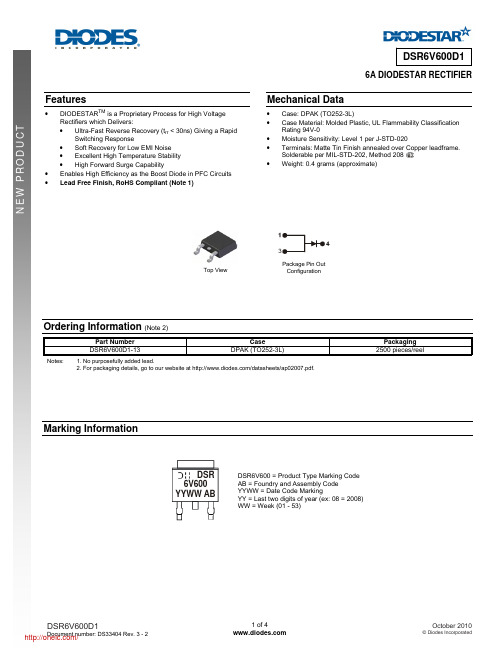
DSR6V600D1
Value
Unit
600
V
6
A
60
A
NEW PRODUCT
Thermal Characteristics
Characteristic Maximum Thermal Resistance Thermal Resistance Junction to Case (Note 3) Thermal Resistance Junction to Ambient (Note 3) Operating and Storage Temperature Range
Solderable per MIL-STD-202, Method 208 • Weight: 0.4 grams (approximate)
Top View
3
Package Pin Out Configuration
Ordering Information (Note 2)
Notes:
Part Number DSR6V600D1-13
IF(AV), AVERAGE FORWARD CURRENT (A)
0.01 0 100 200 300 400 500 600 VR, INSTANTANEOUS REVERSE VOLTAGE (V) Fig. 3 Typical Reverse Characteristics
9
8
7
Based on Lead Temp (TL)
1,000
DSR6V600D1
1,000
CT, TOTAL CAPACITANCE (pF)
NEW PRODUCT
IR, INSTANTANEOUS REVERSE CURRENT (µA)
msdf026-206的参数

msdf026-206的参数msdf026-206是一种具有多个参数的产品,下面我将详细介绍每个参数。
1.产品型号:msdf026-206msdf026-206是一款市面上常见的产品型号,它是由专业制造厂商根据特定的设计要求和技术标准生产的。
2.尺寸:msdf026-206的尺寸为[填写具体尺寸]。
尺寸的大小决定了产品在使用过程中的空间占用以及适用范围,消费者在购买时需要根据实际需求来选择合适的尺寸。
3.功率:msdf026-206的功率为[填写具体功率]。
功率是指单位时间内产生的能量或所需要的功耗,在电子产品中通常以瓦特(W)来表示。
功率的大小反映了产品的耗电情况以及性能表现。
4.电压:msdf026-206的电压为[填写具体电压]。
电压是电力系统中用来驱动电流流动的力量,通常以伏特(V)为单位。
电压的大小与设备的正常运行直接相关,因此在使用时需要确保使用设备的电压与msdf026-206的电压相匹配。
5.响应时间:msdf026-206的响应时间为[填写具体响应时间]。
响应时间指的是产品从接收到指令或者输入信号到作出相应动作的时间间隔。
对于需要高速反应的产品来说,较短的响应时间可以提高用户体验。
6.适用领域:msdf026-206适用于[填写适用领域]。
不同的产品有不同的适用领域,msdf026-206根据其特定的设计和功能特点,可以广泛应用于[填写具体适用领域]。
7.材质:msdf026-206的外壳材质是[填写具体材质],内部主要采用了[填写内部材质]。
材质的选择直接影响产品的质感、使用寿命以及抗摔性能等方面。
根据不同的需求,材质的选择可能会有所不同。
8.控制方式:msdf026-206的控制方式是[填写具体控制方式]。
控制方式决定了用户使用产品时的操作方式,可以是物理按钮、遥控器、应用程序等多种方式。
合适的控制方式能够提高用户便捷性和操作舒适性。
9.温度范围:msdf026-206的工作温度范围是[填写具体工作温度范围]。
意法半导体推出带EMI滤波+ESD防
意法半导体推出带EMI滤波+ESD防
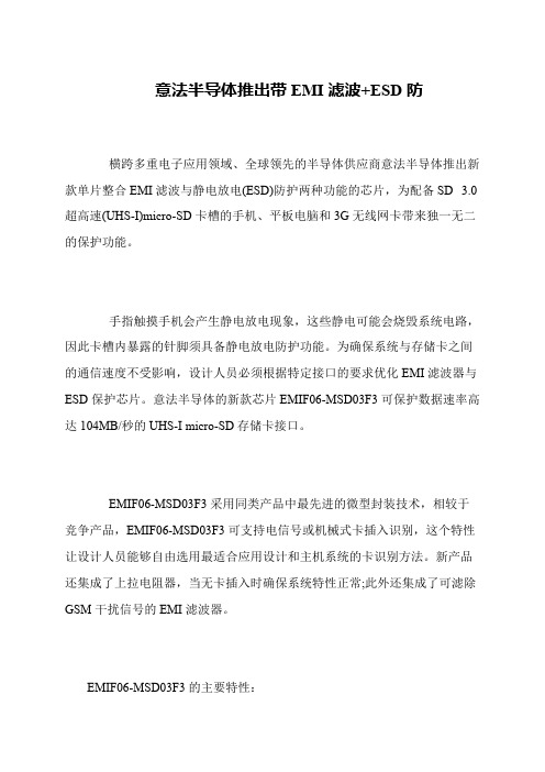
横跨多重电子应用领域、全球领先的半导体供应商意法半导体推出新款单片整合EMI滤波与静电放电(ESD)防护两种功能的芯片,为配备SD 3.0超高速(UHS-I)micro-SD卡槽的手机、平板电脑和3G无线网卡带来独一无二的保护功能。
手指触摸手机会产生静电放电现象,这些静电可能会烧毁系统电路,因此卡槽内暴露的针脚须具备静电放电防护功能。
为确保系统与存储卡之间的通信速度不受影响,设计人员必须根据特定接口的要求优化EMI滤波器与ESD保护芯片。
意法半导体的新款芯片EMIF06-MSD03F3可保护数据速率高达104MB/秒的UHS-I micro-SD存储卡接口。
EMIF06-MSD03F3采用同类产品中最先进的微型封装技术,相较于竞争产品,EMIF06-MSD03F3可支持电信号或机械式卡插入识别,这个特性让设计人员能够自由选用最适合应用设计和主机系统的卡识别方法。
新产品还集成了上拉电阻器,当无卡插入时确保系统特性正常;此外还集成了可滤除GSM干扰信号的EMI滤波器。
EMIF06-MSD03F3的主要特性:。
防静电手册A版
辉烨通讯技术有限公司防静电手册A版受控状态:__________A版_______发放编号:__________ESD-M_____深圳市辉烨通讯技术有限公司2012.10.16 作成,2012-11-1生效作 成会 签 栏 审 核年 月 日 年 月 日李小昀2012年10月16日年 月 日 年 月 日 年 月 日年 月 日 审 核年 月 日 年 月 日 年 月 日 年 月 日 年 月 日 年 月 日 批 准年 月 日 年 月 日 年 月 日年 月 日修 改 履 历修改 日期修改 页次 修改 章节 修改 状态 修改内容摘要 修改申请号填写人 2012-10-16全文 全文 A 、0初次作成李小昀编号 D/ESD-M最短保存期限:至文件作废为止文件批准、修改登记表文件文件名称防静电手册发放----------防静电手册目录----------录-●1防静电方针:辉烨通讯技术有限公司防静电手册防静电方针防静电方针是本公司的防静电管理的纲领性文件,是公司在防静电方面追求的目标,是公司对工作人员和顾客作出的承诺。
保障人员安全,做好静电防护,减少静电伤害,消除品质隐患!2 措施2.1 按照ANSI/ESD-S20.20 (2007)建立文件化的ESD管理体系,加以实施和保持,并持续改进。
2.2对各级人员进行防静电知识培训。
2.3合理配置必要的静电防护装备,保护人员和产品安全。
2.4对全过程进行防护,防止静电敏感产品受到静电损害。
2.5制定可行的防静电管理方案并遵照执行。
2.6定期对静电管理体系进行审核。
总经理:日期:辉烨通讯技术有限公司防静电手册总要求1 2 3 方针按照ANSI/ESD-S20.20 (2007)建立文件化的ESD管理体系,加以实施和保持,并持续改进。
确保作业人员安全、确保ESD敏感产品全过程受到防护,降低非正常损耗,减少不良质量成本,减少潜在不良,提升顾客满意度。
适用范围适用于公司所有的ESD敏感产品的采购、进货、贮存、生产、检验、包装、交付的全过程。
- 1、下载文档前请自行甄别文档内容的完整性,平台不提供额外的编辑、内容补充、找答案等附加服务。
- 2、"仅部分预览"的文档,不可在线预览部分如存在完整性等问题,可反馈申请退款(可完整预览的文档不适用该条件!)。
- 3、如文档侵犯您的权益,请联系客服反馈,我们会尽快为您处理(人工客服工作时间:9:00-18:30)。
November 2008 Rev 11/12EMIF06-MSD02N166-line IPAD™, EMI filter and ESD protectionFeatures■High design flexibility ■Lead free package■Very low PCB space consumption:3.5 mm x 1.2 mm■Very thin package: 0.5 mm ■High efficiency in ESD suppression ■IEC 61000-4-2 level 4■High reliability offered by monolithic integration ■High reduction of parasitic elements through integration and µQFN packagingComplies with following standards:■IEC 61000-4-2 level 4 external pinsApplications■Mobile telephones,■Navigation systems ■Digital still cameras ■Portable devices.DescriptionThe EMIF06-MSD02N16 is a highly integrated device designed to suppress EMI/RFI noise for interface line filtering. It is packaged in micro QFN.This filter includes ESD protection circuitry, which prevents damage to the protected device when subjected to ESD surges.TM: IPAD is a trademark of STMicroelectronicsCharacteristics EMIF06-MSD02N162/121 CharacteristicsTable 1.Absolute ratings (limiting values)SymbolParameterValue UnitV PPESD IEC 61000-4-2Contact discharge on DA Tx_In, CMD_In and CLK_In pins On all other pins Contact discharge Air discharge2812kVT j Maximum junction temperature 125°C T op Operating temperature range - 30 to + 85°C T stgStorage temperature range- 55 to + 150°CEMIF06-MSD02N16Characteristics3/12Figure 5.ESD response to IEC 61000-4-2 (+12 kV air discharge) on one input (V in ) and on one output (V out )Figure 6.ESD response to IEC 61000-4-2 (-12 kV air discharge) on one input (V in ) and on one output (V out )INOUT55V Max39V MaxINOUT-41V Max-34V MaxApplication information EMIF06-MSD02N164/122 Application informationThe EMIF06-mSD02N16 is a dedicated interface device for micro SD card/T -Flash card inmobile phones. The device provides:●ESD protection ●EMI filterering ●Pull-up resistors ●Card detection circuit2.1 ESD protectionEach pin is connected to a TVS diode able to withstand 12 kV on all pins except onDATx_In, CMD_In and CLK_In.2.2 EMI filteringDATx, CMD and CLK lines are immunized against EMI radiations thanks to pi-filters. Toavoid any degradation of the signal integrity at high frequency, the total line capacitance stays lower than 20 pF making the device compatible with a clock frequency up to 52 MHz.2.3 Pull-up resistorsAs recommended by the SD Specifications (Part 1 Physical Layer Version 2.00), all the datalines DATx and the CMD line must be pulled-up with resistors of 10 to 100 k Ω to avoid bus floating not only in SD 4-bit mode but also in SD 1-bit and SPI mode.For the EMIF06-MSD02N16 device the pull-up resistor value has been fixed at 90 k Ω. This value makes the EMIF06-MSD02N16 compatible with most of the level shifters that may be used in the circuit including auto direction-sensing translators known to exhibit a weak current output.2.4 Card detection circuitThe EMIF06-mSD02N16 provides the flexibility to use either mechanical card detection witha dedicated pin connected to the memory card slot or the electrical card detection using the internal pull resistor of DAT3 of the micro SD card/T -Flash card.In case of mechanical card detection, the user must add a pull-up on the circuit connected to the CD (Card Detect) of the micro-SD/T -Flash slot as shown in Figure 8.EMIF06-MSD02N16Application information5/12A pull-up of 90 k Ω is embedded into the EMIF06-MSD02N16. The routing corresponding to the mechanical card detection configuration is shown in Figure 9.Circuit routing for mechanical card detectionIn case of electrical card detection, the user must add a pull-down on the circuit connected to the CD/DAT3 pin of the micro-SD/T -Flash pin as shown in Figure 10.Contact wheninserting the cardSD cardPin 2–CD/DAT3Pin 3–CMD Pin 5–CLK Pin 6–GND Pin 7–DAT0Pin 8–DAT1Pin 4Top level DAT3 pull-upCard detect host inputPin 2–Pin 3Pin 5Pin 6Pin 7Pin 4NCHOST CONTROLLERSD cardDAT3 (CD)50 k ΩGNDV DDOrdering information scheme EMIF06-MSD02N166/12A pull-down of 470k is embedded into the EMIF06-mSD02N16. The routing corresponding to the electrical card detection configuration is shown in the Figure 11. 3 Ordering information schemePin 2Pin 2Pin 3Pin 5Pin 6Pin 4Top levelPin 2DAT3 pull-downPin 2Pin 3Pin 5Pin 6Pin 7Pin 8Pin 4EMIF06-MSD02N16Package information7/124 Package information●Epoxy meets UL94, V0In order to meet environmental requirements, ST offers these devices in ECOP ACK ®packages. These packages have a lead-free second level interconnect. The category of second level interconnect is marked on the inner box label, in compliance with JEDECStandard JESD97. The maximum ratings related to soldering conditions are also marked on the inner box label. ECOP ACK is an ST trademark. ECOPACK specifications are available at .Figure 13.Micro QFN 3.5x1.2 16L Figure 14.MarkingPackage information EMIF06-MSD02N168/12Note:Product marking may be rotated by 90° for assembly plant differentiation. In no case should this product marking be used to orient the component for its placement on a PCB. Only pin1mark is to be used for this purpose.EMIF06-MSD02N16Recommendation on PCB assembly9/125Recommendation on PCB assembly5.1Stencil opening design1.General recommendation on stencil opening designa) Stencil opening dimensions: L (Length), W (Width), T (Thickness).b) General design ruleStencil thickness (T) = 75 ~ 125 µm2. Reference designa) Stencil opening thickness: 100 µmb) Stencil opening for central exposed pad: Opening to footprint ratio is 50%.c)Stencil opening for leads: Opening to footprint ratio is 90%.Aspect Ratio WT----- 1.5≥=Aspect Area L W×2T L W +()---------------------------0.66≥=Recommendation on PCB assembly EMIF06-MSD02N1610/125.2 Solder paste1.Halide-free flux qualification ROL0 according to ANSI/J-STD-004.2. “No clean” solder paste is recommended.3. Offers a high tack force to resist component movement during high speed4.Solder paste with fine particles: powder particle size is 20-45 µm.5.3 Placement1.Manual positioning is not recommended.2. It is recommended to use the lead recognition capabilities of the placement system, notthe outline centering3. Standard tolerance of ± 0.05 mm is recommended.4.3.5 N placement force is recommended. Too much placement force can lead tosqueezed out solder paste and cause solder joints to short. Too low placement force can lead to insufficient contact between package and solder paste that could cause open solder joints or badly centered packages.5. To improve the package placement accuracy, a bottom side optical control should be performed with a high resolution tool.6.For assembly, a perfect supporting of the PCB (all the more on flexible PCB) is recommended during solder paste printing, pick and place and reflow soldering by using optimized tools.5.4 PCB design preference1.To control the solder paste amount, the closed via is recommended instead of openvias.2.The position of tracks and open vias in the solder area should be well balanced. The symmetrical layout is recommended, in case any tilt phenomena caused by asymmetrical solder paste amount due to the solder flow away.分销商库存信息: STMEMIF06-MSD02N16。
