改装手册
DIY电动自行车改装套件用户手册说明书

DIY Electric bike conversion KitsUser ManualPlease read the user manual carefully before starting the conversion process.Please convert the bicycle on the basic of full understanding of the manual.Before putting the device into operation, make sure that the connectors from the controller to the motor are plugged together to the marking.Brief IntroductionTo convert a bicycle is a rewarding project, but caution is advised. Customers converting their own bike are responsible for the safe operation and installation of the kit.Please kindly read the user manual carefully before starting the conversion. We disclaim any responsibility injury, damage or other consequences arising from the use of this product.User PrecautionsWe want have a fun ride, but also safe one, please read following information thoroughly, even if you are an experienced rider, take the opportunity to familiarize yourself with this conversion●Read all of the enclosed installation and operating instructions and follow the instructions, prior to its first use●The e-bike kit has lots of electric parts, do not dismantle the parts, let them fall down or punctured them●The electric parts are fine in the rain but should NEVER be submerged in liquid;●Storage temperature of lithium ion battery is -20~+60 °C●Batteries should be charged immediately after every use and never stored for long periods of time without maintenance charging, if you have to store for a long period of time, please remember to charge it once at least every two months●The bike should be checked carefully after long time idle●Spoke Tension should be checked after 100km and adjusted where necessary●Make sure the tires have proper pressure before riding●Make sure the brakes are operating properly before riding●Always wear a helmet when riding an electric bicycle for your own safety●Adhere to all valid traffic regulations●Keep in mind that other traffic participants may underestimate the speed of an electricbicycle.●Ride with both hands on the handlebars when riding your electric bicycle.Parts IntroductionWhen you open the carton, please find the components as below, please read it carefully.1. Hand-Built motor wheelV-disc brake motor wheel Disc brake motor wheelWhatever what kinds of motor you received, this installation step is similar, please refer for installation step, the installation steps will short of as below.2. Battery & ChargerTube Rear packRear pack Seat PostNew tube ColumnLead acid Charger3. ControllerNormal controllers Complete waterproof controllerTube battery controller New tube battery controller4. Brake levelsEconomic brake levels Water-proof plug brake levels 5. ThrottlesThumb throttle—normal Thumb throttle-----waterproofTwist throttle---normal Twist throttle---waterproof6. PAS (pedal assisted system)Normal PAS Removable PAS7. DisplayLED display LCD display8. Removable motor linesSome motor lines are not removable, please pay attention when you refer packing list.9. One cable systemWhen you assemble, please notice the corresponding plug colors.Installation GuideController cables introduction- All controllers with normal cables; please refer this diagram, no matter the controller shape.Please notice the cable colors must mirror same colors.- All controllers with complete waterproof cables please refer this diagram, no matter what controller shape is, please notice the cable colors must mirror same colors.CAUTION:If the controller you received is different with above two, when you install the other components, please notice the cables of controller and electronic parts should be same, generally the cables and its colors could match with electronic parts.ToolsYou are able to use similar tools or you could buy from local dealer.Step 1: Make sure your bike is suitable for conversionOur e-bike kit is universal and can be used to convert most conversional bicycles, however there are criteria which much be meet first.Your front forks and rear dropouts must be wide enough to accept hub motor. Front fork dropout MUST BE at least 98-102mm for regular bicyclesR ear conversions REQUIRED 133-137mm at least for regular bicyclesBrompton bicyc le’s front fork dropout is 80mm.Please order special motors to convert Brompton bicycle.The opening on the fork or rear frame MUST BE suitable to fit hub motor axles, too wide is not acceptable.★generally the diameter of motor axle is 10mm.Step 2 Transfer your tire & tube & Install the motor wheel:You will need to transfer your existing tire and tube or a new tire and tube to hand-built motor wheel.Front motor wheel (disk or caliper)1.take out the original bicycle wheel and release the caliper2. Dismantle the original disc and install it on the motor wheel.When tight the screws of disc, please tight them in diagonal direction and do not tight too much, or the screws will slip the teeth, because the motor cover is in aluminum material.3. fit the spacers close to motor★ Spacers quantities depend on your bicycle4. fit the spacers on the axle and insert the motor wheel5. tight in all screws6. adjust caliper to suitable location and tighten the screwsRear disc/V brake motor1. Take out the original real bicycle wheel from the bike2. Install the brake disc and freewheel on the motor (when tightening the screws on the disc, tighten them diagonally)3. Install the motor wheel and tight it.Step 3 Install display1.release the screws on the back of the display and fit it on the handle bar2.adjust the display location and tighten the screwsStep 4 Install the brake levers & throttle & handle bars1.take out the original brake levers and grips (left & right)2.insert the brake lines to new electric brake levers3.fit the electric brake levers on the bike and tight the screws (left & right)4.fit the throttle (generally right side)5. 5. fit the new grips (left & right; you may need to warm the grips if they are hard to fit)Step 5 Install PAS (pedal assist sensor)A Normal PAS (you need to use specific bicycle tools to take out the crank set and axis, the normal PAS is installed inside the crank set)1. Undo the crank set and arm2. Take out the arm of the other side and its axle3. F it the mental sensor on the axle, and fit back onto the bicycle, fit disc plate (please notice the direction of mental sensor and disc plate must be congruent with these images. The sensor must be close to disc plate, 1~3mm)4. F it the crank set and arm, tighten the sensor cable on the bicycle.Removable PAS, installed on the left side of the bicycle, crank arm removal not required.1.Fit the disc on the crank axle:2.Apply the adhesive sensor to the frame, please notice it should close to disc, or PASwill not work.Step 6 Install battery and controllerTube battery1.remove the bottle cage on the bicycle2.insert the bracket of tub battery, tight the screws (may look different to photo)3.fit the tube battery, lock it and turn off the battery switch (please refer assemblybatteries chapter)4.connect all electronic lines with controller (please refer controller introduction)Seat post battery1.dismantle the controller boxPlease carefully keep these screws, they are a specialized kind and costly to replace.2.Apply the rubber around the opening hole of controller box, insert the saddle seatstem, adjust the box location and tighten the screws;3.connect all electronic cables with controller (please refer controller introduction)4.put the controller into the box, reassemble the box5.Insert the seat post batteryRear pack battery1.take out the existing rear pack, please go No 2 if this is not existing2.check the rear battery is complete3.fit the rear rack onto the bicycle, adjust and tighten the screws4.insert the battery into the pack, lock the battery5.connect all electronics with the controller6.put the controller into the box, assemble the box.Step 7 Make final adjustments & EnjoyMake sure the brakes are adjusted, the wheel is secure, screws are tighten, everything is functioning as expected, you need to twist the throttle to test the hub motor with the motor wheel lifted off the ground, if anything is not working properly please recheck all of the step of assembly and contact the distributors for help.Now you are ready to have fun riding, be careful and take it slow until you get feel of your e-bike.Take time to learn your new e-bike and how it handles now that is motorized.Ride a few km’s and stop to check everything over again.Be 100% sure that the wheel is secure and nothing has come loose.You should inspect your e-bike and components regularly to ensure all connectors are secure, especially the controller and battery connectors.Before putting the device into operation, make sure that the connectors from the controller to the motor are plugged together to the marking.ChargingCharging plug - to connect local power Charging port - to connect battery1.Insert charging port on battery first, then insert charging plug to mains socket2.The charging signal is red during charging, it turns to green after full charging3.Photos of charging plug & charging port please refer battery introductionsLoad/Unload the batteries1. Please turn the keys left/right to lock or unlock the batteries2. The keys have two functions: to lock the battery and ignite the power (for some units, not others).3. Lead acid could take out the battery socket directly.MaintenanceWe recommend to have the spoke tension of the motor wheel and the torque of all screws checked by a qualified dealer after the first 50km.In order to ensure extended use of the propulsion system, all plug-in contacts of the system should be checked every two to three months and cleaned with a soft and dry brush, if necessary.It must be ensured that no dirt or humidity penetrates the battery docking station when the battery is removed.CleaningCAUTION:Never use a high pressure washer or a garden hose to clean the propulsion system. The force of a water jet could damage the electrical components of the propulsion system.We recommend a soft sponge or a soft brush to clean the bicycle.Use a moist rag to clean the battery docking station.Always use very little water, and keep water away from the electrical contacts.Check the plug-in connections for moisture after cleaning and let these dry, if necessary, before using the bicycle.。
五十铃手册

□车辆改装基本原则N系列载货汽车标准底盘是从各方面综合考察平衡的结果,因此,应最大限度地避免没有必要的改制和安装,确实需要改装时,改装工作应仅限于后述项目,且应按本改装指南所提供的注意事项进行操作。
一、改装单位必须对改装后的整车负责,改装时应考虑以下问题:1、改装部分的结构及改装部分与车架连接的合理性;2、改装后,轴载质量分配的合理性、左右轮胎负荷的均匀性;3、改装时,在原底盘上进行加工的合理性;4、安全及法规限制等。
二、改装后应满足:1、整车总质量不得超过允许的最大总质量,各轴轴载质量不得超过“允许的最大轴载质量”,载荷分布左右应基本均匀,最大偏差不得超过3%;2、足够的维修保养空间。
日常保养的各检查点及润滑点,不进行任何拆卸就能顺利进行;3、车辆外形尺寸不应超过限值,车辆后悬不应超过标准限值;4、改装后的车辆必须满足国家现行的法规要求,不能影响车辆的行驶、制动、安全、转向等性能。
□ 二类底盘的基本外形尺寸□车辆的基本参数○质量参数○发动机○变速箱二、MSB-5S动力输出参数如下:三、MSB-5M动力输出参数如下:四、MSB-5SM动力输出参数如下:○前轴、后桥承载能力□车辆改装须知N系列载货汽车标准底盘涉及改装的部分(我公司不允许除以下项目外的改装)○车架的改装车架的改装涉及钻孔、局部修切、铆接、焊接及车架的加强等。
根据载货汽车用途的一致性原则,车架设计成承载用途,因此,特殊用途加装会导致载荷条件的改变,甚至在载荷很错误: 在纵梁上、下翼缘面钻孔纵梁翼缘面纵梁限制区域小的条件下,每段应力的增加都是变化的,这将导致车架的损坏和断裂。
因此,在进行改装工作时,必须按下列注意事项和要求进行。
一、在车架上加孔1、应严格限制孔的位置,不能随便在车架上加孔,不能在纵梁的上下翼缘面上加孔。
2、应严格限制孔的数量和直径。
① 只允许在指定区域加孔、焊接,而禁止在划线区域钻焊。
不允许钻孔横梁加强梁不允许开缺口◇ 新加孔必须远离原有的孔位或焊缝。
东风系列汽车底盘改装手册

1
EQ1118GAY 系列汽车底盘改装手册
安全须知
制动管路及压缩空气装置
1、 在塑料管路或尼龙管路的附近进行焊接、钻孔磨削以及使用磨擦锯进行工作时,在关键位置 应有必要采取防护措施,将其覆盖或拆下。 2、 更改制动装置时,只允许使用东风汽车有限公司审批过的管路连接件和塑料软管。 3、 不允许变动制动系统内所有阀类部件的位置及状态,如确需更动,应向东风汽车有限公司商 用车技术中心底盘及整车性能开发部进行咨询、联系并取得帮助,避免出现制动安全问题。 4、 进行改装时,管路中的压缩空气要全部释放掉,并排空贮气筒中的压缩空气,使弹簧制动器 进行制动。 5、 在进行制动系统改装时,必须将车轮楔住。
电气设备
当对车辆进行焊接作业时,需要对车辆上的电源系统进行处理,防止车辆上的电子部件 (尤其是各种 控制器,如 EECU, VECU 和 ABS-ECU 等)遭受焊接电流的冲击而造成损坏。对电源系统的处理按 下列步骤进行 : 对装有电磁式电源总开关的车辆
具体操作步骤: 1. 将发动机熄火,断开电源总开关。 2. 拆开蓄电池正极电源线和负极电源线,将正极电源线和负极电源线可靠连接,如图 b)所示。 3. 接通电源总开关。 4. 进行焊接作业。 5. 焊接作业完成后,恢复蓄电池电源线接线,如图 a)所示。 6、 把正极和负极电缆线相连并连到车架上。
东风 EQ1118GAY 系列汽车底盘改装手册
东风汽车有限公司 2008 年 12 月
前言
欢迎您使用东风牌系列载货汽车底盘。
本手册主要介绍了 EQ1118GAY 系列汽车底盘各大总成的匹配和机械性能,为 各类专用汽车改装时提供必要的技术参数和尺寸参数。同时改装企业在利用该 汽车底盘改装各类专用车时,一定要遵守手册中提出的改装要求,否则会给整 车的使用性能和可靠性带来全面的影响。
船舶重大改装实施指南(2016)

船舶重大改装实施指南(2016)中国船级社2016年9月指导性文件GUIDANCE NOTES GD10-2016目录第1章通则 (3)第2章构造、分舱、载重线与稳性 (5)第3章防火、探火和灭火 (5)第4章救生设备与装置 (6)第5章防污染 (6)第6章船体结构和设备 (8)第7章机电设备与系统 (10)第8章船体改装工程控制 (10)第9章船员舱室设备 (13)附录1 油船改装成矿砂船、散货船和双壳油船的适用标准规定 (13)第1章通则1.1 目的和范围1.1.1 本指南旨在为实施船舶重大特征改变的修理、改造和改装及舾装(以下简称“重大改装”)的要求提供指导。
1.1.2 本指南适用于从事国际航行的具有CCS船级和/或申请授予CCS船级的船舶,国内航行海船也可参考使用。
1.1.3 本指南适用于本指南生效日期及以后重大改装的船舶。
本指南生效日期之前正在改装的船舶尽实际可能符合本指南规定。
1.1.4 在应用本指南时,尚应注意船旗国主管机关对重大改装的相关要求。
1.2 定义1.2.1 下列文件的相关定义适用于本指南:(1)CCS《钢质海船入级规范》;(2)国际海上人命安全公约(以下简称SOLAS公约);(3)国际防止船舶造成污染公约(以下简称MARPOL公约);(4)国际载重线公约(以下简称ICLL公约);(5)2006年海事劳工公约(以下简称MLC2006公约)。
1.2.2 本指南有关定义如下:(1)船型:就法定要求而言,系指本指南中所涉及各公约各篇章所对应的船舶类型;就入级要求而言,系指CCS《钢质海船入级规范》所给出的船舶类型。
(2)重大改装日期:除标准及本指南相关章节另有规定外,系指:①签订重大改装合同日期,或;②如无重大改装合同,重大改装工程开始日期,或;③重大改装完成之日。
(3)船舶尺度:系指船舶的船长(L)、型宽(B)和型深(D),其中就船舶入级要求而言,按CCS《钢质海船入级规范》定义确定;就法定要求而言,按IMO相关定义确定。
CA3250P1K2T1改装车手册

接近角 离去角 重心至前轴中心距离 底盘重心高度 推荐车厢长度 型号 最大功率(kW/rpm) 最大扭矩(N. m/rpm) 生产厂家 发动机 型号 最大功率(kW/rpm) 最大扭矩(N. m/rpm) 生产厂家 型号 最大功率(kW/rpm) 最大扭矩(N. m/rpm) 生产厂家 离合器 型式
车轮与轮胎
轮胎/个数 轮辋 外偏距 mm
8JS118:
i1=11.4, i2=7.94, i3=5.63, i4=4.06, i5=2.81, i6=1.96, i7=1.39, i8=1.000, IR=11.35
生产厂 驱动桥 型式 生产厂 车架 纵梁断面尺寸 加强板尺寸 车架总成宽度 空(满)车架上表面离地高度 车架有效长度 后桥中心处车架上平面至地 面高度
1240/900,1200, 1088,800,1760 mm 3400,3500,3550,3600,4000+1350 mm 1914,2020/1847,1860mm 250,265mm 1
CA3250P1K2T1 8110,7680,7285 kg 3330,3200,3270 kg /4780,4480,4015 kg 24950kg 6990/17960kg
6990,7290,7278, 6790,8405 mm 2455 mm 2730,2745 mm
一汽集团 CA6DF2-24 177/2300 890/1400
一汽集团 CA6DF2-26 192/2300 930/1400 一汽集团 单片、干式、 膜片弹簧压紧式离 合器,摩擦片外径Ф430 或Ф 380mm;液压气助力操纵机构 一汽集团 CA7T156 8JS118
4
PDF 文件使用 "pdfFactory Pro" 试用版本创建
CNG车辆改装质量手册程序文件汇编

CNG车辆改装质量手册《特种设备安全检察条例》《TSGZ0004-2007特种设备制造、安装、改造、维修质量保证体系基本要求》、TSGR3001-2006《压力容器安装改造维修许可规则》、GB/T18437.1/2.2001《燃气汽车改装技术条件》、GB/T19240-2003《压缩天然气汽车专用装置的安装要求》、QC/T245.2002《压缩天然气汽车专用装置技术条件》等标准规范目录CNG车辆改装质量手册程序文件1管理和评审控制程序2文件控制程序3记录控制程序4合同和评审控制程序5设计控制程序6材料、零部件控制程序7作业(工艺)控制程序8焊接控制程序9检验与试验控制程序10设备和检验试验控制程序11不合格品(项)控制程序12质量改进与服务控制程序13人力资源管理程序14基础设施和工作环境管理程序15供方控制程序16标识和可追溯性控制程序17产品防护控制程序18内部质量审核控制程序19产品的监视和测量控制程序20数据分析和信息传递管理程序21纠正措施控制程序22预防措施控制程序23质量记录控制程序表格记录1 CNG汽车改装组装操作、检验记录2 CNG汽车安装及检验过程卡3 CNG系统安装工艺及支架制作工艺卡4 支架制作、焊接、检验记录表5 气瓶支架强度试验记录6 车用气瓶及管道置换记录7 气密性试验记录8 车用气瓶安全质量合格证明9 CNG汽车安装(改装)合格证10 安装告知单11 安装许可证(复印件)12 气瓶出厂资料(监检证书、质量证明书、合格证、使用说明书)13 车用气瓶安装监督检查项目表、车用气瓶安装检测检验证书CNG车辆改装质量手册1质量体系和质量方针1.1我公司的质量体系的适用范围是我公司对用户在用汽车所进行的压缩天然气汽车专用装置的改装(简称CNG改装)。
质量方针和质量目标亦是为此而提出的。
1.2质量方针和质量目标是公司经营战略的重要组成部分,是对用户的承诺,是公司奋斗的质量宗旨和行为准则。
HOWO改装手册第七版
(双转向)
3225+1365 300 482.5 2358 2295 1336 1249 300 750 2661 1940 1345 1225
1950+2475 270(曼车架) 759.25 2651.75 1945 1298 1178
7
HOWO-A7 系列 CNG 牵引车
驱动型式 轴距 车架断面高度 牵引座前置距 前回转半径 后间隙半径 鞍座上平面 离地高度 空载 满载 300 450 2050 1758 1345 1225 4×2 3800 270(曼车架) 483.5 2017 1778 1298 1178 3800+1350 300 290 2551 2140 1406 1331 6×4 3800+1400 270(曼车架) 321 2520 2166 1334 1244
8
斯太尔(王)系列
驱动型式 轴距 车架断面高度 牵引座前置距 前回转半径 后间隙半径 鞍座上平面 离地高度 空载 满载 4×2 3500 243 560 2190 1800 1278 1200 6×4 2925+1350 243 290 2540 2130 1435 1357
驱动型式 轴距 车架断面高度 牵引座前置距 前回转半径 后间隙半径 鞍座上平面 离地高度 空载 满载
表112牵引车鞍座参数牵引车鞍座参数howo不含a7系列牵引车驱动型式42曼车架轴距35003500车架断面高度300300空气270270空气牵引座前置距4504504835前回转半径2200220021665后间隙半径1720172017535鞍座上平面离地高度空载134513121334满载122512771244驱动型式64曼车架轴距3200140032001400车架断面高度300300huv300空气270270huv270空气牵引座前置距300300300321321321前回转半径260026002600262026202620后间隙半径213021302130211021102110鞍座上平面离地高度空载140614071377133413091289满载133113321342124412341254双转向轴距322513651800230018002500车架断面高度300300270曼车架牵引座前置距中桥后1807006805前回转半径240028002780后间隙半径227018381858鞍座上平面离地高度空载133613451298满载124912251178howo系列cng牵引车驱动型式轴距38003800135038001400车架断面高度300270曼车架300270曼车架牵引座前置距4504835300321前回转半径19631688523652139后间隙半径2200222020802100鞍座上平面离地高度空载1367130014211351满载1261119413461275howo系列lng牵引车驱动型式轴距42003800135038001400车架断面高度300270曼车架300270曼车架牵引座前置距4504835300321前回转半径17181666521502129后间隙半径2200168520802100鞍座上平面离地高度空载1367130014211351满载1261119413461275howo系列ng牵引车驱动型式62双转向62双转向62后提升轴距180025001800250038001365车架断面高度270曼车架270曼车架300牵引座前置距681681前回转半径176917272066后间隙半径182518252450鞍座上平面离地高度空载131613161411满载122112211305howoa7系列牵引车驱动型式42曼车架轴距35
CA3256P1K2T1A80-Q359改装手册06_3_6
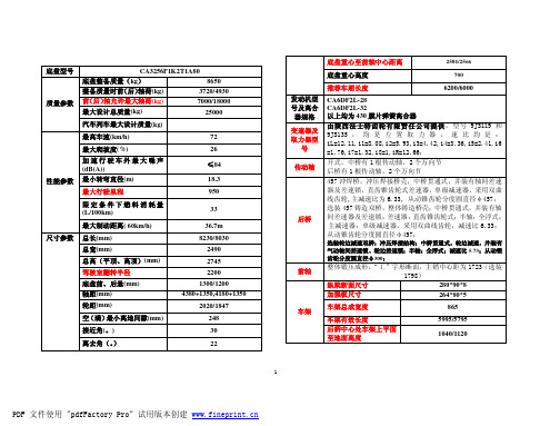
自卸车底盘车架总成图
4
PDF 文件使用 "pdfFactory Pro" 试用版本创建
底盘重心至前轴中心距离 底盘型号 CA3256P1K2T1A80 底盘整备质量(kg) 8650 整备质量时前 (后) 轴荷(kg) 3720/4930 前 (后) 轴允许最大轴荷(kg) 7000/18000 最大设计总质量(kg) 汽车列车最大设计质量(kg) 最高车速(km/h) 最大爬坡度(%) 加速行驶车外最大噪声 (dB(A)) 最小转弯直径(m) 最大行驶里程 限定条件下燃料消耗量 (L/100km) 最大制动距离( 60km/h) 尺寸参数 总长(mm) 总宽(mm) 总高(平顶、高顶)(mm) 驾驶室翻转半径 底盘前、后悬(mm) 轴距(mm) 轮距(mm) 空 (满) 最小离地间隙(mm) 接近角(。) 离去角(。 ) 72 26 ≤84 18.3 950 33 后桥 36.7m 8230/8030 2490 2745 2200 1300/1200 4380+1350,4180+1350 2020/1847 248 30 22 车架 前轴 25000 底盘重心高度 推荐车厢长度 发动机型 号及离合 器规格 变速器及 取力器型 号 传动轴
选装轮边减速双桥:冲压焊接结构;中桥贯通式,轮边减速,并装有 气动轴间差速锁、轮边差速锁;半轴:全浮式;减速比 5.73;从动锥 齿轮分度圆直径φ300;
整体锻压成形, “工”字形断面,主销中心距为 1723(选装 1798) 纵梁断面尺寸 280*90*8 加强板尺寸 264*80*5 车架总成宽度 车架有效长度 后桥中心处车架上平面 至地面高度 865 5995/5795 1040/1120
2581/2566 700
易驰车载电脑长城酷熊改装安装手册实例

安 装 手 册E as y D ri v er安装须知:1. 拆卸主机前要先确认原车各种功能是否正常,确认原车音响系统播放正常,车载电脑必须在原车的各功能皆正常的情况下方可安装。
2. 拆卸、安装过程中要小心翼翼插拔各类接口,切勿用力过大;主机后部的接线切勿折放。
3. 拆卸下的螺丝请放在固定位置,如档位后侧的储物盒。
安装流程一:准备工作在实施拆卸步骤前,请检查手刹是否拉起,档位是否调至空挡。
安装流程二:拆除装饰面板第一步:轻拆下面板,注意:中间的风量调节旋钮是同面板一体的第二步:面板完全卸下后,开始拔除面板后面的电联线路E as y D ri v er第三步:把原车面板放置到较安全的地方,防止损坏安装流程三:取下原车CD ,加装车载电脑第一步:拆下原车CD 。
原车CD 是固定在两片铁架上的,铁架由四E as y D ri v er个螺丝固定在车上,拧掉螺丝便可卸下CD ,拔除CD 后面的音箱和电源连线, AUX 口接线及内置FM 信号接收器连线。
卸下固定原车CD 的两片铁架,安装在车载电脑设备主机上。
第二步:接好原车中控台控制线。
这些连接线是中控台里控制空调、灯光、时钟等用的,跟音响没有关系。
在安装的时候重新把这些线原位插回去即可。
第三步:将其固定在支架上的车载电脑主机接好线,只需把相应的插E as y D ri v er头接到主机背面即可(接线请参照ED7touch 使用手册),接下来按照之前几个步骤将其还原,至此,车载电脑的安装就算完成了。
E as y D ri v er。
车辆改装蒙迪欧致胜日间行车灯安装指导手册

保要有保护物,切勿让夹持工具损 伤前保油漆面
支架安装完毕
9
3.3 安装线束 ①
拆下大灯接头 在离接头大约12cm处剪断7 号孔位和12号孔位 的导线
套上热缩管,拨开导线表皮 约5mm,按下表所示对应关 系与日间行车灯的导线对接, 用压接钳 压紧
压接筒 热缩管
大灯导线 7 日间行车灯导线 3 功能 接地线
长安福特
蒙迪欧致胜日间行车灯安装指导手册
第二版
1
目录
1. 序 2. 主要工具
3. 安装步骤
4. 注意事项
2
1. 序
本手册用于指导蒙迪欧致胜日间行车灯加装 本手册适用车型如下
1) 蒙迪欧致胜 2.0 Core 2) 蒙迪欧致胜 2.3 Trend 3) 蒙迪欧致胜 2.3 Ghia 4) 蒙迪欧致胜 Elite GTDI 203PS 5) 蒙迪欧致胜 Ghia GTDI 203PS
拆下保险杠后,未安装日间 行车灯保险杠内侧图示
5
3.1 拆卸原支架 ②
1 3 8 7
5
4
2
9
6
用一字起 按图示顺序依次将 原有盖板从焊点处剥离
请谨慎拆卸,切勿损坏保险 杠蒙皮
盖板拆卸后图示
6
3.2 安装新支架 ①
用风动抛光机 (砂纸规格 ≥1000目)打磨焊点区域,去 掉表面焊接痕迹直至表面光滑
复原前保 复原大灯
结束
13
4. 注意事项
1) 安装新支架时操作环境温度必须满足3M胶带储存 使用要求,即温度≥16°C 2) 粘接支架前,配合面一定要清理干净 3) 支架安装操作过程中(尤其保压工序),注意保护前 保油漆面
4) 安装热缩管时, 热缩枪用最低档
骊威音响加装AUX手册
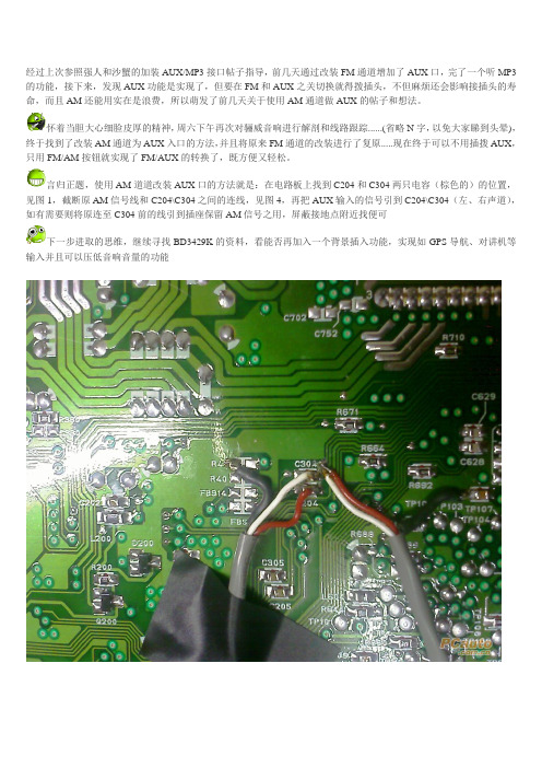
经过上次参照强人和沙蟹的加装AUX/MP3接口帖子指导,前几天通过改装FM通道增加了AUX口,完了一个听MP3的功能,接下来,发现AUX功能是实现了,但要在FM和AUX之关切换就得拨插头,不但麻烦还会影响接插头的寿命,而且AM还能用实在是浪费,所以萌发了前几天关于使用AM通道做AUX的帖子和想法。
怀着当胆大心细脸皮厚的精神,周六下午再次对骊威音响进行解剖和线路跟踪......(省略N字,以免大家睇到头晕),终于找到了改装AM通道为AUX入口的方法,并且将原来FM通道的改装进行了复原.....现在终于可以不用插拨AUX,只用FM/AM按钮就实现了FM/AUX的转换了,既方便又轻松。
言归正题,使用AM道道改装AUX口的方法就是:在电路板上找到C204和C304两只电容(棕色的)的位置,见图1,截断原AM信号线和C204\C304之间的连线,见图4,再把AUX输入的信号引到C204\C304(左、右声道),如有需要则将原连至C304前的线引到插座保留AM信号之用,屏蔽接地点附近找便可
下一步进取的思维,继续寻找BD3429K的资料,看能否再加入一个背景插入功能,实现如GPS导航、对讲机等输入并且可以压低音响音量的功能
其实如果确实觉得无必要保留AM功能,那么那条原AM信号引去插座的线也可以省掉,这样改装更简单。
东风商用车底盘改装手册(通用)

二、鉴于东风底盘商品化的销售原则 东风公司不能对所有改装单位及改装车的改装方案负技术责任;改装单位必须对改装后 的整车负责,建议考虑以下内容:
1、改装部分结构及改装部分与车架连接的合理性; 2、改装后轴载质量分配的合理性、左右轮胎负荷的均匀性; 3、因改装需要在原底盘上进行加工的合理性; 4、安全及法规限制的项目等。 三、改装后,整车总质量不得超过允许的最大总质量,各轴轴载质量不得超过允许的最大轴
半挂牵引车的改装
牵引鞍座的改装 挂车电气部分的改装 挂车制动部分的改装
改装要求
尼龙管的改装 车架的改装 油漆 发动机悬置系统的改装 进、排气系统改装 供油系统及油门操纵系统改装 冷却系统改装 电器系统的改装 制动系统的改装
底盘改装基本原则
一、底盘改装的基本涵义 对东风公司提供的不带车箱的二类底盘进行功能性的结构安装,不涉及任何总成的更 换。
HOWO系列改装手册(电子版)第8.0版
5
3、T5G 驾驶室 本体采用 MAN 公司 TGA 窄体驾驶室本体改进而成,全气囊四点悬浮驾驶室悬架,平地板 超大空间,可以配置中间坐椅,真正准乘三人不超员,750 毫米宽豪华卧铺,超大储物空间, 为驾乘人员提供舒适地享受。
T5G-M 中长型,司机坐椅可选装空气座椅,电控自动空调,暖风空调一体化,翻转式卧 铺,双锁止结构安全带,可选装中间坐椅。 T5G-W 加长型,750 毫米宽单卧铺,其他配置同 M 型。 T5G-V 加长高顶型,双卧铺,其他同 W 型。 4、豪瀚驾驶室 H17--豪瀚加长驾驶室。基本配置为单卧铺,新款座椅,可调节方向盘,航空式仪表台, 成熟奔驰分体自动空调系统;四点全浮+横向稳定杆式悬架(前后位螺旋弹簧)+减震装置,双 锁止结构安全带。 H18--豪瀚高顶驾驶室。基本配置为双卧铺,其它同 H17 H16--豪瀚中长驾驶室. 基本配置为单卧铺,其它同 H17
驱动型式 轴距 车架断面高度 牵引座前置距 前间隙半径 后回转半径 鞍座上平面 离地高度 空载 满载 300 300 2600 2130 1406 1331
6×4 3200+1400 300/HUV 300 2600 2130 1407 1332 300/空气 300 2600 2130 1377 1342 270 321 2620 2110 1334 1244
注:以上数据为 HW12 后桥(270 为 MCY13 桥), 90#金刚鞍座,315/80R22.5 轮胎。 ①如选装标准 90#鞍座,鞍座上平面离地高度相应加 35;如选装双自由度 90#鞍座,鞍座上平面离地高度相 应加 124。 ②如可选装重汽低位鞍座的车型选装重汽低位鞍座时,鞍座上平面离地高度在相应标准鞍座的基础上减 33。
一、 车型 产品图谱
100P国3改装手册第1版

100P 国 3 系列载货汽车底盘改 装 手 册庆铃汽车股份有限公司二零零九年六月前言感谢您使用庆铃 100P 国 3 系列载货汽车底盘。
本改装手册主要介绍了五十铃 100P 国 3 系列汽车底盘的主要技术参 数和各大总成的结构参数特点,为各类改装行业提供必要的技术参数。
改 装企业使用本手册进行改装时务必严格遵守本手册要求,否则可能对底盘 的使用性能和可靠性造成不利影响。
在改装过程中请参考本手册要求内容进行改装,若有不清楚部分或对 底盘提出特殊要求时,请及时与庆铃汽车股份有限公司联系。
希望本手册在改装过程中对您有所帮助,本手册与车辆使用说明书配 合使用,可进一步增加您对车辆的了解。
本手册包括以下底盘:序号 轴距 驾驶室 1 2 3 4 5 6 7 8 9 单排 2490 双排 单排 双排 单排 3360 双排 底盘型号 QL10408EARY QL10408EWRY QL10408EWR1Y QL10408FARY QL10508FWRY QL10508HARY QL10408HARY QL10508HWRY QL10408HWRY 备注 后桥单轮胎2765由于本公司产品的结构和性能在持续改进,包括有新的选装零件增 加,可能会造成本手册与实际车辆不一致的情况,敬请谅解。
本手册为 2009 年 6 月第 1 版。
本改装手册中的所有数据、图解和规格均以出版时的最新资料为准。
本公司有权随时对本手册进行更改,预先不予通知。
本手册版权归庆铃汽车股份有限公司所有,未经书面同意,不管是全部还 是其中之一部分,均不得翻版和复制。
庆铃汽车股份有限公司 中国·重庆目●底盘改装的基本原则 ●100P 国 3 系列车型简介 ●底盘主要参数及简图 ●底盘主要总成结构参数录●各底盘申报公告《强检统计表》 ●第一部分:底盘改装作业 ●第二部分:上装与底盘安装连接底盘改装的基本原则一、 底盘改装的定义 对庆铃汽车股份有限公司提供的二类底盘(不带货箱)进行功 能性的结构安装,不涉及重要总成的更换。
宝马3系后排娱乐加装手册

© BMW AG, Munich
01 29 0 400 767
2/2007(Z/Z )
1
符号意义: 指示注意危险的说明。
指示注意特殊功能的说明。
指示说明或其它文字的结束。
安装信息 确保电缆/管路往车上装时未受到扭结或损伤。 由这种损坏产生的花费BMW AG不予赔付。 安装的附加电缆/管路须用电缆扎带固定。 如果指定的针脚孔被占用,则须使用过桥、双压褶或双线端。 所示图片均为左位驾驶型汽车;右位驾驶型汽车的程序类同。 订购说明 检查颜色版本与技术装备。以下零件未包括在组件中,需要另行订购(有关零件号与明细参见EPC)。 对于便携式DVD系统安装组件 - 安装座 C - 多媒体游戏机与附件 M 对于报警系统附加包 - 饰件Q - 传感器O 特殊设备列表 改装改装包时必须考虑以下特殊设备: SA 302 SA 403 报警系统 玻璃车顶
10. 裁切顶衬(仅无SA 403 的汽车) ............................................................................. 17 11. 裁切顶衬(仅带SA 403 的汽车) ............................................................................. 18 12. 安装罩板与连接车顶灯 ............................................................................................. 20 13. 收尾工作与编码 ...................................................................................................... 22 14. 线路图 ................................................................................................................... 23
欧曼改装手册(4)
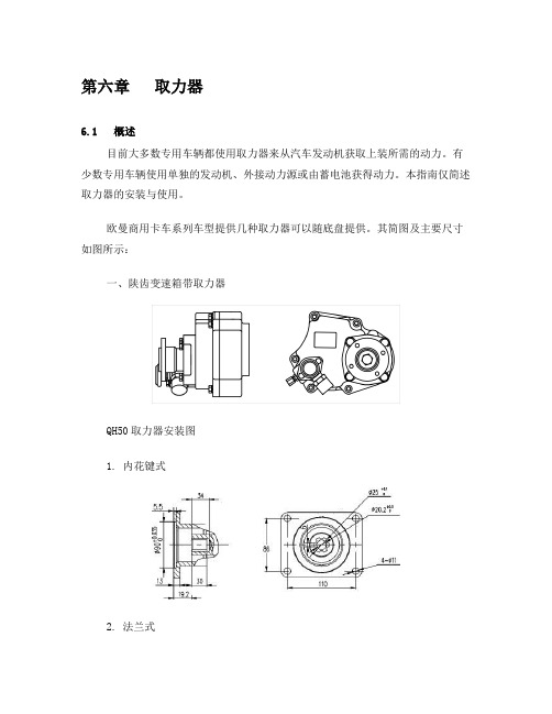
第六章取力器6.1 概述目前大多数专用车辆都使用取力器来从汽车发动机获取上装所需的动力。
有少数专用车辆使用单独的发动机、外接动力源或由蓄电池获得动力。
本指南仅简述取力器的安装与使用。
欧曼商用卡车系列车型提供几种取力器可以随底盘提供。
其简图及主要尺寸如图所示:一、陕齿变速箱带取力器QH50取力器安装图1. 内花键式2. 法兰式QH50取力器安装图输出轴旋转方向:与发动机旋转方向相同取力器速比表变速箱型号图号变速器档位4/8 3/7 2/6 1/5RT11509C 01取力器总速比0.98 1.32 1.78 2.42 008JS118B 02取力器总速比0.98 1.35 2.06 3.11 028JS118T 01 取力器总速比0.98 1.32 1.91 2.688JS130T 01取力器总速比0.98 1.32 1.91 2.68 02二、大齿变速箱带取力器1. 法兰式4205NG-010取力器安装图4205N31-010取力器安装图4205E02-010取力器安装图变速箱型号代号取力器总速比取力器输出旋转方向取力器输出扭矩DC6J85TZ 02 1.716 与发动机旋向相反450N·mDC6J70T 11 1.361 与发动机旋向相反300 N·mDC7J100TA 091.004 与发动机旋向相反600 N·m 05DC7J120 12 1.604 与发动机旋向相反600 N·m2. 内花键式变速箱型号代号取力器总速比取力器输出旋转方向取力器输出扭矩DC6J70T 11 1.438 与发动机旋向相反300 N·mDC6J85 01 1.845 与发动机旋向相反588 N·mDC6J85 01 1.845 与发动机旋向相反588 N·m三、哈齿变速箱带取力器1. 内花键式CA7-95C05取力器安装图变速箱型号代号取力器总速比取力器输出旋转方向取力器输出扭矩CA7-100 02 1.128 与发动机旋向相反400N·mCA7-100 07 1.128 与发动机旋向相反400N·mCA7-100 02 1.128 与发动机旋向相反400N·mCA7-100 07 0.95 与发动机旋向相反400N·m CA6-80G取力器安装图型号代号取力器总速比取力器输出旋转方向取力器输出扭矩CA6-75 00 1.031 与发动机旋向相反260N·m 取力器气缸输出接头为:Q80505(M10×1)2. 法兰式CA7100AQ26取力器安装图型号代号取力器总速比取力器输出旋转方向取力器输出扭矩CA7-100 02 1.128 与发动机旋向相反400N·mCA7-100 02 1.128 与发动机旋向相反400N·m四、东风变速箱带取力器变速箱型号代号取力器总速比取力器输出旋转方向取力器输出扭矩DF5S550 01 1.18 与发动机旋向相反145 N·m五、搅拌车全功率取力器安装图发动机型号取力器总速比取力器输出旋转方向取力器输出功率/转速WD615.44 1 与发动机旋向相同150Kw/ 2200r/minWD615.46全功率取力器(BJ3381DSPJY)发动机型号取力器总速比取力器输出旋转方向取力器输出功率/转速WD615.46 1 与发动机旋向相同150Kw/ 2200r/min6.2 取力器的选择与改装改装厂家可以按照需要重新选择取力器。
乖巧虎98K改装教程

乖巧虎98K改装教程
乖巧虎98K改装,是一种将普通的98K步枪升级为更加强大的武器的改装方法。
乖巧虎98K改装的方法非常简单,可以让枪械变得更加强大和精良,不仅可以满足高端玩家的需求,还可以在更大的半径和高的杀伤力上赢得更多的优势。
首先,改装者需要拆卸98K,然后检查其材料是否符合标准。
在这一步工作完
成后,改装者可以更换枪管口径来提高射击距离;更换枪管并添加消声器以减少后压;为实现更高精度而更换各种传动结构;以感应枪灯和瞄准装置的形式进行可视化改装;更换必要部件使枪支与个人口袋或配件结构更加一致;最后,可以根据改装者的需要更改涂装颜色,使枪支有更潮流的外观。
乖巧虎98K改装,可以使枪支更佳的性能,使改装者在游戏中取得更好的表现;也可以在习惯改装内容上进行调节,同时还可以自定义射击音色和选择性外观;更重要的是,它可以让枪支变得更加精细,使用时更加舒适。
乖巧虎98K改装是一项重要的枪支改装方法,它的好处多多,可以提高枪的精
准性和射击距离,并为改装者提供更高的游戏体验;还可以定制既和谐又潮流的外观,满足客户的个性化需求;当然,在改装之前,应该首先查看改装手册,以确保材料符合质量标准,以免出现意外情况。
欣瑞达屏幕改装教程

欣瑞达屏幕改装教程
要进行欣瑞达屏幕改装,你需要有一些基本的工具和技巧。
下面是一些步骤,可以帮助你完成这个过程:
1. 准备工具:你需要一把螺丝刀、塑料片、吹尘工具、透明胶带等工具。
2. 取下原屏幕:首先,关闭电源并断开所有连接。
然后,使用螺丝刀拆开设备的外壳,找到原屏幕并小心地将其取下。
这可能需要拆卸一些连接器和螺丝。
3. 清洁设备:在安装新屏幕之前,务必清洁设备的内部和外部。
使用吹尘工具或软毛刷将灰尘和杂物从设备中清除。
4. 安装新屏幕:将新屏幕放在原屏幕的位置上,并确保连接器和螺丝线都正确地与设备的内部连接。
5. 测试屏幕:将设备连接到电源,并测试新屏幕是否正常工作。
确保显示效果正常,没有死像或亮度问题。
6. 关闭设备:如果新屏幕顺利工作,关闭设备并重新拧紧所有螺丝。
确保所有连接器和线缆都安全连接。
这些步骤只是一个大致的概述,具体的改装过程可能因不同设备和屏幕型号而有所不同。
在进行任何改装之前,建议你查阅设备的相关手册或寻求专业技术人员的帮助。
Garmin G5000 综合飞行仪表台改装手册说明书
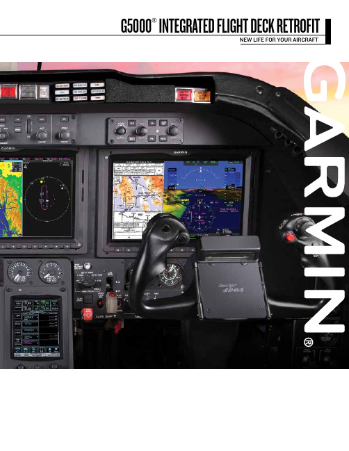
G5000® INTEGRATED FLIGHT DECK RETROFITNEW LIFE FOR YOUR AIRCRAFTNEW LIFE FOR YOUR AIRCRAFTThe Garmin G5000 is engineered to reduceworkload, improve situational awareness andgive flight crews the tools to enhance safety andefficiency on every flight.Large, high-resolution color screens depict aircraftperformance, navigation, weather, terrain andtraffic information with easy-to-interpret displays.A proven, digital attitude and heading referencesystem delivers high-precision data for theinstruments on the Primary Flight Displays (PFD).Plus, with the addition of optional Garmin SVT ™synthetic vision technology, pilots see a realistic3-D view of topographic features surroundingtheir aircraft. Garmin SVT tracks the navigationsystem’s terrain database to recreate this “virtualreality” landscape on the pilot and copilot PFDs.Meanwhile, detailed moving-map graphics on the Multi-function Display show the aircraft’s current position relative to navigational aids, airways, flight plan routings, and more. Flight crews can also overlay weather, lightning, traffic, terrain, and obstruction for improved awareness, while still viewing essential engine status, crew alerting and fuel-systems data on the MFD’s multi-pane screen for easier monitoring and faster troubleshooting. All of these functions are managed through infrared, touchscreen Aircraft System Management controllers. Simply tap the screen to access the window, frequency or menu item, making even advanced operations intuitive and easy.TECHNOLOGY ON DISPLAY Your corporate jet has proven itself to be a vital tool for your organization. But as it ages, you might have some important questions about its future. Fortunately, you also have an easy answer. The Garmin G5000® integrated flight deck retrofit. With it, you’ll add even more value and utility to your aircraft—as well as boost the service life and reliability of this valuable asset.The G5000 not only brings the most advanced navigation capabilities to your aircraft, but it also delivers savings and more efficient operation—while also meeting upcoming global requirements for ADS-B.With a G5000 retrofit, you remove 150 pounds or more of hardware and wiring. That’s enough weight savings to carry an additional team member, or more baggage, or more fuel. Plus, its state-of-the-art capabilities should add significantly to your estimated resale value at trade-up time, and until then, predictable flat rates for repairs help keep costs of ownership low—and confidence levels high. And it’s backed by our 365/24/7 customer support that’s earned No. 1 rankings from readers of Aviation International News and Professional Pilot for more than a decade, which is only a call away.Garmin G5000: It’s the clear-as-glass choice for giving your aircraft a fresh new lease on life. No other upgrade comes close—for anything close to the price.To fully leverage the performance and capability of your aircraft, the G5000 offers an advanced Automatic Flight Control System (AFCS) that’s engineered to provide the latest autopilot functionality—including the easiest one-button coupled go-around capabilities in the industry. Passengers will appreciate the silky smooth climbs, turns and descents, and your pilots will appreciate its precise navigation guidance for all phases of flight. The system is fully enabled for satellite-based navigation, which allows approaches into runways that may not be served by ground-based electronic approach aids. And it can automatically fly any procedure published in the navigation database. That means your aircraft will have access to more all-weather landing options at more airports throughout the world.AUTOPILOT INTEGRATION With the Flight Data Logging feature, the G5000®automatically stores critical flight and engine parameters, so if there’s an abnormality, data can quickly be made available to a maintenance facility to help expedite troubleshooting and minimize service downtime. TROUBLESHOOTING DATAThe G5000 offers the latest in performance planning and management functions. Using inputs from the onboard aircraft systems—as well as airframe-specific data from the aircraft flight manual—G5000 automatically calculates critical engine N1 speeds and maximum operating airspeeds, and it offers prebuilt profiles for climb, cruise, descent, vertical navigation and climb to cruise, which keep the aircraft where you need it, at the speeds required. And building on these capabilities, optional SurfaceWatch technology provides flight crews with visual and aural alerts that warn if the aircraft is about to takeoff or land on too short a runway, on the wrong runway, or on a taxiway. The G5000 provides your flight crews with additional instrument approach options, including radius-to-fix (RF) legs, which are sometimes found in complex Instrument Approach Procedures. This capability provides pilots and operators with greater access to airports in areas of the world where instrument approaches are nestled among challenging terrain environments.NEXTGEN NAVIGATION CAPABILITY To help reduce the risk of accidents involving controlled flight into terrain (CFIT), the G5000 is provisioned for “forward looking” terrain avoidance (FLTA) capability with Class B (and optional Class A) Terrain Awareness and Warning Systems (TAWS). These systems compare the aircraft’s current position with the navigation system’s internal databases to determine where conflicts may exist.Optional TAWS-A capabilities alert for excessive rates of descent, altitude loss after takeoff, excessive closure rate to terrain, excessive downward deviations from an approach, and the impending flight into terrain when the aircraft is not set up in landing configuration.TERRAIN AWARENESScrews have every possible advantage when it comes to “seeing and avoiding” in busy, high-density airspace. In fact, G5000 includes dual GTX 3000 ADS-B transponders that integrate with existing traffic systems to provide the crews with the NEXRAD weather, current airport conditions, forecasts, temporary flight restrictions, cloud tops, winds aloft, and more, which aids in flight planning and routing. And for the best in onboard real-time weather And G5000 allows flight crews and passengers to stay connected from virtually anywhere on the planet. Garmin Connext ® wireless connectivity enables voice calling, text messaging, position reporting, and more. MAKE G5000WORK FOR YOU The Garmin G5000 flight deck modernization program offers a state-of-the-art integrated flight deck that yields advanced capabilities and an exceptional in-flight experience that surpasses other solutions available on the market today — all the while solving a broad range of worldwide operational requirements.To learn more about upgrading your Beechjet 400A/Hawker 400XL cockpit with the G5000, contact Dave Brown, Garmin Integrated Flight Deck Sales Manager at *********************or 913-440-1714.PERFORMANCE AWARENESS/aviation ©2017 Garmin Ltd. or its subsidiaries. All rights reserved Specifications and descriptions are preliminary and subject to change without notice.The Bluetooth word mark and logos are registered trademarks owned by Bluetooth SIG, Inc. and any use of such marks by Garmin is under license.GARMIN INTERNATIONAL, INC.1200 East 151st Street, Olathe, KS 66062p: 866.739.5687 f: 913.397.8282GARMIN (EUROPE) LTD., Liberty House, Hounsdown Business Park,Southampton, Hampshire, SO40 9LR, U.K.p: +44 (0)87.0850.1243 f: +44 (0)23.8052.4004GARMIN SINGAPORE PTE. LTD., 46 East Coast Road #05-06, Singapore 428766 p: 65.63480378 f: 65.63480278e:************************0217 M02-10243-00。
