ACTR3003中文资料
MIC3003GFL;MIC3003GFL TR;中文规格书,Datasheet资料

MIC3003GFLFOM Management IC with Internal CalibrationMLF and MicroLead Frame are registered trademarks of Amkor Technology, Inc.General DescriptionThe MIC3003GFL is a fiber optic module controller which enables the implementation of sophisticated, hot-pluggable fiber optic transceivers with intelligent laser control and an internally calibrated Digital Diagnostic Monitoring Interface per SFF-8472. It essentially integrates all non-data path functions of an SFP/SFP+ transceiver into a tiny (3mm x 3mm ) MLF ® package. It also works well as a microcontroller peripheral in transponders or 10Gbps transceivers. The MIC3003GFL uses the same die as the MIC3003 with all its functions, but in a smaller package and different pin out. A highly configurable automatic power control (APC) circuit controls laser bias. Bias and modulation are temperature compensated using dual DACs, an on-chip temperature sensor, and NVRAM look-up tables. A programmable internal feedback resistor provides a wide dynamic range for the APC. Controlled laser turn-on.An analog-to-digital converter converts the measured temperature, voltage, bias current, transmit power, and received power from analog to digital. An EEPOT provides front-end adjustment of RX power. Each parameter is compared against user-programmed warning and alarm thresholds. Analog comparators and DACs provide fast monitoring of received power and critical laser operating parameters. Data can be reported as either internally calibrated or externally calibrated.An interrupt output, power-on hour meter, and data-ready bits add user friendliness beyond SFF-8472. The interrupt output and data-ready bits reduce overhead in the host system. The power-on hour meter logs operating hours using an internal real-time clock and stores the result in NVRAM.In addition to the features listed above, the MIC3003 features an extended temperature range, options to mask alarms and warnings interrupt and TXFAULT, a reset signal source, and the ability to support up to four chips with the same address on the serial interface. It also supports eight-byte SMBus block writes.Communication with the MIC3003 is via an industry standard 2-wire SMBus serial interface. Nonvolatile memory is provided for serial ID, configuration, and separate OEM and user scratchpad spaces.Datasheets and support documentation can be found on Micrel’s web site at: .Features• Packaged in a ultra small (3mm x 3mm) 24-pin MLF ® package • Extended temperature range• Alarms and warnings interrupt and TXFAULT masks • Capability to support up to four devices on one SMBus • APC or constant-current laser bias• Turbo mode for APC loop start-up and shorter laser turn on time • Supports multiple laser types and bias circuit topologies • Integrated digital temperature sensor• Temperature compensation of modulation, bias, bias fault and alarm thresholds via NVRAM look-up tables • NVRAM to support GBIC/SFP serial ID function • User writable EEPROM scratchpad• Reset signal compatible with some new systems requirements • Diagnostic monitoring interface per SFF-8472 – Monitors and reports critical parameters:temperature, bias current, TX and RX optical power, and supply voltage– S/W control and monitoring of TXFAULT, RXLOS, RATESELECT, and TXDISABLE – Internal or external calibration– EEPOT for adjusting RX power measurement • Power-on hour meter • Interrupt capability• Extensive test and calibration features • 2-wire SMBus-compatible serial interface • SFP/SFP+ MSA and SFF-8472 compliant • 3.0V to 3.6V power supply range • 5V-tolerant I/OApplications• SFP/SFP+ optical transceivers• SONET/SDH transceivers and transponders • Fibre Channel transceivers • 10Gbps transceivers• Free space optical communications • Proprietary optical linksTypical ApplicationOrdering InformationPart NumberPackage Marking Junction Temp.RangePackage Type Lead FinishMIC3003GFL GFL 3003 with Pb-Free bar-line indicator–45°C to +105°C24-pin (3mm x 3mm) MLF ® Pb-Free,NiPdAuMIC3003GFLTR (1) GFL 3003 with Pb-Free bar-line indicator–45°C to +105°C24-pin (3mm x 3mm) MLF ® Pb-Free,NiPdAuNote:1. Tape and Reel.ContentsGeneral Description (1)Features (1)Pin Configuration (8)Pin Configuration (8)Pin Description (MIC3003GFL only) (8)Absolute Maximum Ratings (10)Operating Ratings (10)Electrical Characteristics (10)Electrical Characteristics (12)Electrical Characteristics (13)Serial Interface Timing Diagram (14)Serial Interface Address Maps (15)Block Diagram (18)Analog-to-Digital Converter/Signal Monitoring (18)Alarms and Warnings Interrupt Source Masking (19)Alarms and Warnings as TXFAULT Source (21)Latching of Alarms and Warnings (21)SMBus Multipart Support (21)QGOP Pin Function (21)Calibration Modes (22)A/ External Calibration (22)Voltage (22)Temperature (22)Bias Current (22)TX Power (22)RX Power (23)B/ Internal Calibration (23)Computing Internal Calibration Results (23)C/ Reading the ADC Result Registers (25)RXPOT (25)Laser Diode Bias Control (25)Laser Modulation Control (26)Power On and Laser Start-Up (27)Fault Comparators (28)SHDN and TXFIN (29)Temperature Measurement (30)Diode Faults (30)Temperature Compensation (30)Alarms and Warning Flags (32)Control and Status I/O (32)System Timing (34)Warm Resets (36)Power-On Hour Meter (36)Test and Calibration Features (37)Serial Port Operation (38)Block Writes (38)Acknowledge Polling (39)Write Protection and Data Security (39)OEM Password (39)OEM Mode and User Mode (39)Detailed Register Descriptions (40)Alarm Threshold Registers (40)Temperature High Alarm Threshold (40)Temperature Low Alarm Threshold (40)Voltage High Alarm Threshold (40)D[7] read/write (40)Bias Current High Alarm Threshold (41)Bias Current Low Alarm Threshold (41)TX Optical Power High Alarm Threshold (41)TX Optical Power Low Alarm Threshold (42)RX Optical Power High Alarm Threshold (42)RX Optical Power Low Alarm Threshold (42)Warning Threshold Registers (43)Temperature High Warning Threshold (43)Temperature Low Warning Threshold (43)Voltage High Warning Threshold (43)Voltage Low Warning Threshold (44)Bias Current High Warning Threshold (44)Bias Current Low Warning Threshold (44)TX Optical Power High Warning (44)TX Optical Power Low Warning (45)RX Optical Power High Warning Threshold (45)RX Optical Power Low Warning Threshold (45)Checksum (CHKSUM) Checksum of bytes 0 - 94 at serial address A2h (45)ADC Result Registers (46)Temperature Result (46)Voltage (46)Laser Diode Bias Current (46)Transmitted Optical Power (47)Received Optical Power (47)Control and Status (CNTRL) (47)Application Select Control Mode (ASCM) (48)Alarm Flags (50)Alarm Status Register 0 (ALARM0) (50)Alarm Status Register 1 (ALARM1) (50)Warning Flags (51)Warning Status Register 0 (WARN0) (51)Warning Status Register 1 (WARN1) (51)Extended Control and Status (ECNTRL) (52)OEM Password Entry (OEMPW) (52)Power-On Hours (POHh and POHl) (53)Data Ready Flags (DATARDY) (53)User Control Register (USRCTL) (54)RESETOUT (54)OEM Configuration Register 0 (OEMCFG0) (55)OEM Configuration Register 1 (OEMCFG1) (56)OEM Configuration Register 2 (OEMCFG2) (57)APC Setpoint 0, 1, and 2 (APCSET0, APCSET1, APCSET2) Automatic Power Control Setpoint (58)Modulation Setpoint 0, 1, and 2 (MODSET0, MODSET1, and MODSET2) Nominal V MOD Setpoint (58)I BIAS Fault Threshold (IBFLT) Bias Current Fault Threshold (59)Transmit Power Fault Threshold (TXFLT) (59)Loss-Of-Signal Threshold (LOSFLT) (59)Fault Suppression Timer (FLTTMR) Fault Suppression Interval in Increments of 0.5 ms (60)Fault Mask (FLTMSK) (60)OEM Password Setting (OEMPWSET) (61)OEM Calibration 0 (OEMCAL0) (61)OEM Calibration 1 (OEMCAL1) (63)LUT Index (LUTINDX) (64)OEM Configuration 3 (OEMCFG3) (64)BIAS DAC Setting (APCDAC) Current VBIAS Setting (65)Modulation DAC Setting (MODDAC) Current VMOD Setting (66)OEM Readback Register (OEMRD) (66)OEM Configuration 4 (OEMCFG4) (67)OEM Configuration 5 (OEMCFG5) (68)OEM Configuration 6 (OEMCFG6) (69)Power-On Hour Meter Data (POHDATA) (70)OEM Scratchpad Registers (SCRATCHn) (71)RX Power Coefficient Look-up Table (RXLUTn) (71)Calibration Constants (CALCOEFn) (72)Manufacturer ID Register (MFG_ID) Identifies Micrel as the manufacturer of the device. Always returns 2Ah (72)Device ID Register (DEV_ID) (73)Package Information (74)Figure 1. MIC3003 Block Diagram (18)Figure 2. Analog-to-Digital Converter Block Diagram (18)Figure 3. Internal Calibration RX Power Linear Approximation (25)Figure 4. RXPOT Block Diagram (25)Figure 5. APC and Modulation Control Block Diagram (26)Figure 6. Programmable Feedback Resistor (26)Figure 7. Transmitter Configurations Supported by MIC3003 (26)Figure 8. V MOD Configured as Voltage Output with Gain (27)Figure 9. MIC3003 Power-On Timing (OE = 1) (28)Figure 10. Fault Comparator Logic (28)Figure 11. Saturation Detector (29)Figure 12. RXLOS Comparator Logic (29)Figure 14. Transmitter On-Off Timing (34)Figure 15. Initialization Timing with TXDISABLE Asserted (34)Figure 16. Initialization Timing with TXDISABLE Not Asserted (34)Figure 17. Loss-of-Signal (LOS) Timing (35)Figure 19. Successfully Clearing a Fault Condition (36)Figure 20. Unsuccessful Attempt to Clear a Fault (36)Figure 21. Write Byte Protocol (38)Figure 22. Read Byte Protocol (38)Figure 23. Read_Word Protocol (38)Figure 24. Eight-Byte Block Write Protocol (39)Table 1. Serial Interface Address Map, Device Address = A0h (15)Table 2. Serial Interface Address Map, Device Address = A2 (15)Table 3. Serial Interface Address Map (Temperature Compensation Tables), Device Address = A4h (16)Table 4. Serial Interface Address Map (OEM Configuration Registers), Device Address = A6h (17)Table 5. A/D Input Signal Ranges and Resolutions (19)Table 6. V AUX Input Signal Ranges and Resolutions (19)Table 7. Alarms Interrupt Sources Masking Bits (20)Table 8. Warnings Interrupt Sources Masking Bits (20)Table 9. RESETOUT Clear Delay (21)Table 10. LSB Values of Offset Coefficients (23)Table 11. Internal Calibration Coefficient Memory Map – Part I (24)Table 12. Internal Calibration Coefficient Memory Map – Part II (24)Table 13. Shutdown State of SHDN vs. Configuration Bits (27)Table 14. Shutdown State of V BIAS vs. Configuration Bits (27)Table 15. Shutdown State of V MOD vs. Configuration Bits (27)Table 16. Temperature Compensation Look-up Tables (30)Table 17. APC Temperature Compensation Look-Up Table (31)Table 18. I MOD Temperature Compensation Look-Up Table (31)Table 19. I BIAS Comparator Temperature Compensation Look-Up Table (31)Table 20. BIAS Current High Alarm Temperature Compensation Table (31)Table 21. MIC3003 Alarm and Warning Events (33)Table 22. Test and Diagnostic Features (37)Pin Configuration24-Pin MLF® (ML)Pin Description (MIC3003GFL only)Pin Number Pin Name Pin Function1 VDDD Power supply input for digital functions.Open-drain output. Can be selected (via OEMCFG3 bit 7) to be an open-drain GPO or an active-2 QGPOlow, open-drain, pulsed reset signal output controlled by the status of bits [0-2] of byte A2h: FFh.3 GNDD Ground return for digital functions.Digital input. Receiver Rate Select input. OR’ed with soft rate select bit SRS0 to determine the4 RS0state of the RRSOUT pin. The state of this pin is always reflected in the RS0S bit.If bit 4 (IE) in the USRCTL register is set to 0 (its default value), this pin is configured as an analog5 VIN/INTinput. If IE bit is set to 1, this pin is configured as an open-drain output.Analog input: Multiplexed A/D input for monitoring supply voltage, with a 0V to 5.5V input range.Open-drain output: outputs the internally generated active-low interrupt signal /INT.6 CLK Digital input. Serial clock input.7 DATA Digital I/O, open-drain, bi-directional serial data input/output.Digital input; Active high. The transmitter is disabled when this input is high or the STXDIS bit is8 TXDISABLEset to 1. The state of this input is always reflected in the TXDIS bit.Digital Output; Open-Drain, with programmable polarity. If OEMCFG5 bit 4 is set to 0, a high level9 TXFAULTindicates a hardware fault impeding transmitter operation. If OEMCFG5 bit 4 is set to 1, a low levelindicates a hardware fault impeding transmitter operation. The state of this pin is always reflectedin the TXFLT bit.Digital Input; Transmitter Rate Select Input; OR’ed with soft rate select bit SRS1 to determine the10 RS1state of the TRSOUT pin. The state of this pin is always reflected in the RS1S bit.Analog Input. Multiplexed A/D converter input for monitoring received optical power. The input11 VRXrange is 0 to V REF. A 5-bit programmable EEPOT on this pin provides coarse calibration andranging of the RX power measurement.Pin Number Pin Name Pin Function12 SHDN/TXFINDigital output/Input; programmable polarity. When used as shutdown output (SHDN), OEMCFG3bit 2 set to 0, SHDN is asserted at the detection of a fault condition if OEMCFG4 bit 7 is set to 0. IfOEMCFG4 bit 7 is set to 1, a fault condition will not assert SHDN. When programmed as TXFIN, itis an input for external fault signals to be OR’ed with the internal fault sources to drive TXFAULT.13 VILD+Analog Input. Multiplexed A/D input for monitoring laser bias current via a sense resistor (signalinput); accommodates inputs referenced to V DD or GND (see pin 14 description).14 VILD–Analog Input. Reference terminal for the multiplexed pseudo-differential A/D converter inputs formonitoring laser bias current via a sense resistor (VILD+ is the sensing input). Tie to V DD or GNDto reference the voltage sensed on VILD+ to V DD or GND, respectively.15 VDDA Power supply input for analog functions.16 GNDA Ground return for analog functions.17 VMPDAnalog Input. Multiplexed A/D converter input for monitoring transmitted optical power via amonitor photodiode. In most applications, VMPD will be connected directly to FB. The input rangeis 0 - V REF or 0 - V REF/4 depending upon the setting of the APC configuration bits18 FBAnalog Input. Feedback voltage for the APC loop op-amp. Polarity and scale are programmablevia the APC configuration bits I OEMCFG1. Connect to V BIAS if APC is not used.19 VMODAnalog Output. Buffered DAC output to set the modulation current on the laser driver IC. Operateswith either a 0– V REF or a (V DD–V REF) – V DD output swing so as to generate either a ground-referenced or a V DD referenced programmed voltage. A simple external circuit can be used togenerate a programmable current for those drivers that require a current rather than a voltageinput.20 VMOD–Analog input. This pin is the inverting terminal of the VMOD buffer op-amp. Connect to VMOD(gain = 1) or a feedback resistor network to set a different gain value.21 VBIASAnalog output. Buffered DAC output capable of sourcing or sinking up to 10mA under control ofthe APC function to drive an external transistor or the APCSET pin of a laser diode driver for laserdiode DC bias. The output and feedback polarity are programmable to accommodate either anNPN or a PNP transistor to drive a common-anode or common-cathode laser diode.22 COMPAnalog output. Compensation terminal for the APC loop. Connect a capacitor between this pin andGNDA or V DDA with the appropriate value to tune the APC loop time constant to a desirable value.23 RRSOUT/GPO Digital Output. Open-Drain or push-pull.If OEMCFG3 bit 4 is set to 0, RRSOUT is selected. It represents the receiver rate select as per SFF. This output is controlled by the SRS0 bit OR’ed with RS0 input and is open drain only.If OEMCFG3 bit 4 is set to 1, GPO is selected. General-purpose, non-volatile output, it is controlled by the GPO configuration bits in OEMCFG3.24 RXLOS/TRSOUT Digital output. This programmable polarity, open-drain outputs has two purposes:If OEMCFG6 bit 2 = 0, indicates the loss of the received signal as indicated by a level of received optical power below the programmed RXLOS comparator threshold; may be wire-OR’ed with external signals. Normal operation is indicated by a low level when OEMCFG6 bit 3 is set to 0 and a high level when OEMCFG6 bit 3 is set to 1. RXLOS is de-asserted when VRX > LOSFLTn. The LOS bit reflects the state of RXLOS whether driven by the MIC3003 or an external circuit.If OEMCFG6 bit 2 = 1, TRSOUT is selected. This signal represents the transmitter rate select as per the SFF specification. This output is controlled by the SRS1 bit OR’ed with the RS1 input.Absolute Maximum Ratings(1)Power Supply Voltage, V DD.......................................+3.8V Voltage on CLK, DATA, TXFAULT, VIN, RXLOS, TXDISABLE, RS0, RS1.........................–0.3V to +6.0V Voltage On Any Other Pin.....................–0.3V to V DD+0.3V Power Dissipation, T A = 85°C....................................1.5W Junction Temperature (T J).......................................150°C Storage Temperature (T S).......................–65°C to +150°C Soldering (20 sec.)...................................................260ºC ESD Ratings(3)Human Body Model..................................................2kV Machine Model.......................................................300V Operating Ratings(2)Power Supply Voltage, V DDA/V DDD...........+3.0V to +3.6V Ambient Temperature Range (T A) .......–40°C to +105°C Package Thermal ResistanceMLF® (θJA).................................................60°C/WElectrical CharacteristicsFor typical values, T A = 25°C, V DDA = V DDD = +3.3V, unless otherwise noted. Bold values are guaranteed for +3.0V ≤ (V DDA = V DDD)≤ 3.6V, T(min)≤ T A≤ T(min), (8)Symbol Parameter Condition Min Typ Max Units Power SupplyCLK = DATA = V DDD= V DDA; TXDISABLE low; all DACs at full-scale; all A/D inputs at full-scale; all other pins open. 2.3 3.5 mAI DD SupplyCurrentCLK = DATA = V DDD= V DDA; TXDISABLEhigh; FLTDAC at full-scale; all A/D inputsat full-scale; all other pins open.2.33.5 mAV POR Power-on Reset Voltage All registers reset to default values;A/D conversions initiated. 2.92.98 VVUVLOUnder-Voltage Lockout Threshold Note 5 2.5 2.73 VVHYSTPower-on Reset Hysteresis Voltage 170 mVtPORPower-on Reset Time V DD > V POR, Note 4 50 µs V REF ReferenceVoltage 1.2101.2251.240 V ΔV REF/ΔV DDAVoltage Reference Line Regulation 1.7 mV/V Temperature-to-Digital Converter CharacteristicsLocal Temperature MeasurementError–40°C ≤ T A≤ +105°C, Note 6 ±1 ±3 °Ct CONV Conversion Time Note 4 60 mst SAMPLE SamplePeriod 100 ms Voltage-to-Digital Converter Characteristics (V RX, V AUX, V BIAS, V MPD, V ILD±)Voltage Measurement Error –40°C ≤ T A≤ +105°C, Note 6 ±1 ±2.0 %fst CONV Conversion Time Note 4 10 mst SAMPLE Sample Period Note 4 100 ms Notes:1. Exceeding the absolute maximum rating may damage the device.2. The device is not guaranteed to function outside its operating rating.3. Devices are ESD sensitive. Handling precautions recommended. Human body model, 1.5k in series with 100pF.4. Guaranteed by design and/or testing of related parameters. Not 100% tested in production.5. The MIC3003 will attempt to enter its shutdown state when V DD falls below V UVLO. This operation requires time to complete. If the supply voltage fallstoo rapidly, the operation may not be completed.6. Does not include quantization error.分销商库存信息:MICRELMIC3003GFL MIC3003GFL TR。
3003新一代推车专业级(LED)说明书

引言尊敬的用户:欢迎使用SW-3000系列红外乳腺检查仪。
“三维”红外乳腺检查仪能得到您的信任,我们深表荣幸。
本说明书的用途在于帮助您正确地使用本产品,内容包括概述、结构特征及工作原理、技术特性、安装说明、使用说明、注意事项、故障分析与排除、保养及维护、售后服务等。
在安装和使用本产品之前,请您务必先仔细阅读随机配送的所有资料,特别是本说明书中安全信息及其他条款所提及的注意事项。
这会有助于您更好地使用本产品。
另外,在使用过程中,如果您有什么问题,请来电、来函查询,或登陆三维网站,我们定当竭诚为您服务。
品牌电脑,打印机等享受全国联保的部分请咨询其免费服务电话,以获得高品质的维护。
免责声明本说明书的描述不代表对本产品规格和软、硬件配置的任何说明。
有关产品规格和配置情况,请查阅本产品的相关协议、装箱单或向产品销售商咨询。
在本说明书编制过程中,已力求内容的正确和完整,但不能保证本手册没有任何错误和疏漏。
徐州市三维医疗设备有限公司坚持不断优化、改善自己的产品和服务,为此保留对本说明书描述的产品及本说明书的内容随时进行修改的权利,恕不另行通知。
如您在使用本说明书过程中发现本产品的实际情况与本说明书有不一致之处,如您想得到最新的信息或有任何问题和想法,欢迎致电我们或登陆三维网站垂询。
有限保证/保修本产品附带了标准服务承诺(保修内容),我们将按照该保修内容为您提供售后服务。
超出本标准的服务承诺,三维公司不提供服务,您应要求向您提供本产品的机构或人员按其承诺为您提供售后服务支持。
在法律允许的最大限度内,在任何情况下徐州市三维医疗设备有限公司无须对下列任何一项负责:1、第三方对您的索赔要求(人身死亡、伤害,不动产和相关有形财产的损害赔偿除外);2、您的记录或数据的丢失或损坏;3、特别的、附带的或间接的损害或任何后果性的经济损失(包括利润和储蓄金的损失),即使徐州市三维医疗设备有限公司已被告知发生上述损失的可能性时,也是如此;4、由于您安装非随本产品提供的软件或硬件产品引起的故障,经判定不是三维产品本身的问题;5、由于您未在本说明书所规定的环境使用本产品,或未按使用说明书所规定的操作方法引起的故障;6、不可抗力因素导致产品损坏的情况。
前线安全UltraRAE 3000+复合物特异性监测仪产品介绍说明书

Company Reg No: SC260789 VAT Reg No: GB 828 8779 58t:+44(0)141 771 7749e:*************************.ukUnit F, 230 Parkway Point, Springhill Parkway,D A T A S HE E TThe UltraRAE 3000+ is one of the most advanced Compound-Specific Monitors on the market. Its Photoionization Detector’s (PID) extended range of 0.01 to 10,000 ppm in VOC mode and 10 ppb to 200 ppm inbenzene-specific mode makes it an ideal instrument for applications,from entry pre-screening during refineryand plant maintenance to hazardousmaterial response, marine spill response and refinery down-stream monitoring.•Dual detection mode for total benzeneexposure assessment: 60-second snapshot or 15-minute STEL measurement•High sensitivity to benzene provides a lower detection range for future benzene exposure limits •Lower risk of false alarms through advanced speciation method•Total VOC measurement mode with extended range of 0.01 to 10,000 ppm•Versatile VOC or Benzene-Specific modes•Cost effective solution and low-cost RAE-Sep TM tubes •Reflex PID Technology TM•Highly specific readings, combining a 9.8eV UV lamp and RAE-Sep™ benzene tube•Built-in humidity sensor with Automatic temperature-controlled sampling time calculation•See-through Sampling probe design for instant tube-breakthrough visibility•Highly connectivity capability through multiple wireless module options•Multi-language support•Easy access to lamp, sensor and battery in seconds without tools•Confined space entry pre-screening during refinery and plant maintenance•Hazardous material response •Marine spill response•Refinery down-stream monitoring •Plant overhaulF E AT U R E S & B E NE F I T SA PPLIC AT IO N SWorkers can easily and quickly obtain VOC readings anywhere in the facility with the RAE Systems UltraRAE 3000+UltraRAE 3000+Portable Handheld Compound-Specific VOC MonitorMONITOR ONLY INCLUDES:•UltraRAE 3000+ Monitor, Model PGM-7360•Wireless communication module built-in •Travel Charger•RAE UV lamp and RAE-Sep™ Tubes •Flex-I-Probe™ and short probe •External filter •Red rubber boot•Alkaline battery adapter •Lamp-cleaning kit •Tool kit•Lithium-ion (Li-Ion) battery with universal AC/DCcharger and international plug kit •Soft leather carrying caseMONITOR WITH ACCESSORIES KIT:•Hard transport case with pre-cut foam padding •Charging/download cradle•5 porous metal filters and O-rings •Organic vapor zeroing kit•Gas outlet port adapter and tubing OPTIONAL CALIBRATION KIT ADDS:•Calibration gas, 34L, as specified•Calibration regulator and flow controller OPTIONAL GUARANTEEDCOST-OF-OWNERSHIP PROGRAM:•4-year repair and replacement warranty •Annual maintenance service1Contact RAE Systems for country-specific wireless approvals and certificates. Specifications are subject to change.For more information Europe, Middle East, AfricaLife Safety Distribution GmbHTel: 00800 333 222 44 (Freephone number)Tel: +41 44 943 4380 (Alternative number)Middle East Tel: +971 4 450 5800 (Fixed Gas Detection) **************************AmericasHoneywell Analytics Distribution Inc.Tel: +1 847 955 8200Toll free: +1 800 538 0363***********************Honeywell RAE Systems Phone: +1 408 952 8200Toll Free: +1 888 723 4800Asia PacificHoneywell Analytics Asia Pacific Tel: +82 (0) 2 6909 0300India Tel: +91 124 4752700China Tel: +86 10 5885 8788-3000**************************Technical ServicesEMEA:**********************US:***************************AP:***************************Datasheet_UltraRAE 3000_+_DS-1018-_EN ©2019 Honeywell International Inc.Thank you for reading this data sheet. Please notet:e:*************************.uk。
ACTR304.3中文资料
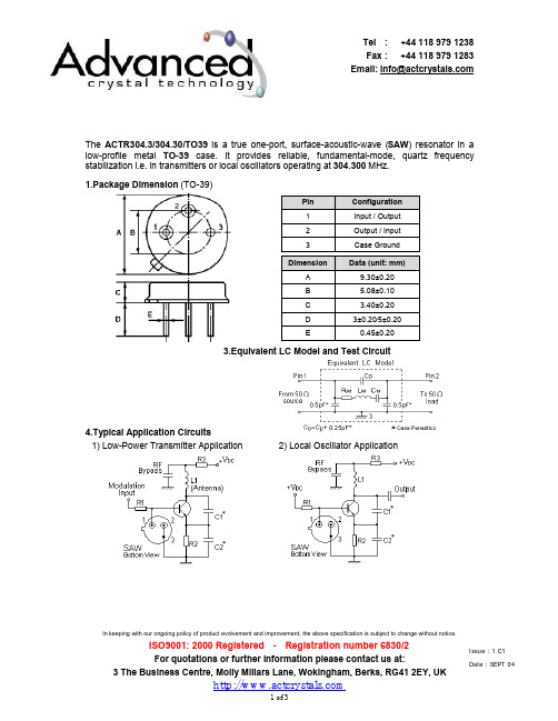
In keeping with our ongoing policy of product evolvement and improvement, the above specification is subject to change without notice.ISO9001: 2000 Registered - Registration number 6830/2 For quotations or further information please contact us at:3 The Business Centre, Molly Millars Lane, Wokingham, Berks, RG41 2EY, UKThe ACTR304.3/304.30/TO39 is a true one-port, surface-acoustic-wave (SAW ) resonator in a low-profile metal TO-39 case. It provides reliable, fundamental-mode, quartz frequency stabilization i.e. in transmitters or local oscillators operating at 304.300 MHz.1.Package Dimension (TO-39)3.Equivalent LC Model and Test Circuit4.Typical Application Circuits1) Low-Power Transmitter Application 2) Local Oscillator ApplicationPin Configuration 1 Input / Output 2 Output / Input 3 Case GroundDimensionData (unit: mm) A 9.30±0.20 B 5.08±0.10 C 3.40±0.20 D3±0.20⁄5±0.20E 0.45±0.20Issue : 1 C1 Date : SEPT 04In keeping with our ongoing policy of product evolvement and improvement, the above specification is subject to change without notice.ISO9001: 2000 Registered - Registration number 6830/2 For quotations or further information please contact us at:3 The Business Centre, Molly Millars Lane, Wokingham, Berks, RG41 2EY, UK5.Typical Frequency Response6.Temperature Characteristics7.Performance7-1.Maximum Ratings RatingValueUnitsCW RF Power Dissipation0 dBm DC Voltage Between Any Two Pins ±30V VDC Case Temperature-40 to +85°C7-2.Electronic CharacteristicsCharacteristicSymMinimumTypicalMaximumUnitsAbsolute Frequencyf C 304.225304.375MHz Centre Frequency(+25°C ) Tolerance from 304.300 MHz∆f C ±75 kHz Insertion Loss IL 1.4 2.0 dB Unloaded Q Q U 14,800 Quality Factor50 Ω Loaded Q Q L 2,200 Turnover TemperatureT 0 25 55 °C Turnover Frequencyf 0 f C kHz Temperature StabilityFrequency Temperature CoefficientFTC 0.032 ppm/°C 2 Frequency Aging Absolute Value during the First Year |f A | ≤10 ppm/yr DC Insulation Resistance Between Any Two Pins1.0 M Ω Motional ResistanceR M 17.5 26 Ω Motional Inductance L M 135.2692 µH Motional CapacitanceC M 2.0243 fF RF Equivalent RLC ModelPin 1 to Pin 2 Static Capacitance C 02.12.42.7pFIssue : 1 C1 Date : SEPT 04In keeping with our ongoing policy of product evolvement and improvement, the above specification is subject to change without notice.ISO9001: 2000 Registered - Registration number 6830/2 For quotations or further information please contact us at:3 The Business Centre, Molly Millars Lane, Wokingham, Berks, RG41 2EY, UKi CAUTION: Electrostatic Sensitive Device. Observe precautions for handling!1. The centre frequency, f C , is measured at the minimum IL point with the resonator in the 50Ω test system.2. Unless noted otherwise, case temperature T C = +25°C±2°C.3. Frequency aging is the change in f C with time and is specified at +65°C or less. Aging may exceed thespecification for prolonged temperatures above +65°C. Typically, aging is greatest the first year after manufacture, decreasing in subsequent years.4. Turnover temperature, T 0, is the temperature of maximum (or turnover) frequency, f 0. The nominal frequency atany case temperature, T C , may be calculated from: f = f 0 [1 - FTC (T 0 - T C )2].5. This equivalent RLC model approximates resonator performance near the resonant frequency and is providedfor reference only. The capacitance C 0 is the measured static (non-motional) capacitance between Pin1 and Pin2. The measurement includes case parasitic capacitance.6. Derived mathematically from one or more of the following directly measured parameters: f C , IL, 3 dB bandwidth,f C versus T C , and C 0.7. The specifications of this device are based on the test circuit shown above and subject to change orobsolescence without notice.8. Typically, equipment utilizing this device requires emissions testing and government approval, which is theresponsibility of the equipment manufacturer.9. Our liability is only assumed for the Surface Acoustic Wave (SAW) component(s) per se, not for applications,processes and circuits implemented within components or assemblies.Issue : 1 C1 Date : SEPT 04。
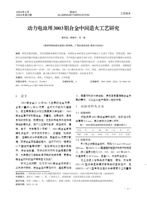
动力电池用3003铝合金中间退火工艺研究
0前言3003铝合金以Al 和Mn 为主要的合金元素,含有少量的Cu 和Zn 元素,由于它不能热处理强化,故主要是通过冷加工提高其力学性能[1]。
3003铝合金属于变形铝合金,质量轻、延展性好,具有良好的成形性、耐腐蚀性、优良的导电导热性和焊接性能等优点,被广泛应用于能源、航空航天、建筑、电子、汽车等多个领域[2-3]。
3003铝合金常用铸轧法生产,该方法投资较小、流程短、效率较高[4]。
但铸轧时冷却速度过快,易造成Mn 元素扩散慢,致使合金存在晶粒粗大、组织不均匀、强度低以及塑性较差等问题[5],在后续加工过程中易裂开,综合性能差,无法达到对材料日益提高的要求。
尤其是近几年新能源领域的快速发展,更是给铝合金材料的生产带来巨大挑战[6]。
针对上述问题,此文对3003铝合金中间退火工艺进行研究,使合金组织更加均匀、晶粒更加细小,提高材料的力学性能,满足目前高端铝合金发展的需求,为工业化生产提供一定的参考。
1试验材料及方法1.1试验材料试验选用3003铝合金铸轧坯料,坯料经冷轧后厚度为2mm ,其化学成分如表1所示。
表13003铝合金坯料的化学成分(质量分数/%)合金3003Fe 0.28Si 0.6Mg ≤0.05Mn 1.32Cu 0.18Zr 0.12Al 余量1.2试验方法取5块上述铝合金坯料,规格为2mm×150mm×200mm ,在SRJX-4-13高温箱式电阻炉中进行中间退火,退火温度分别为325、355、385、415和450℃,升温速度为10℃/min ,保温2h ,然后取出空冷。
对上述退火后样品进行磨抛、腐蚀,然后用4XC-PC 型光学显微镜观察样品的显微组织。
在HBRVU-187.5型号布洛维氏光学硬度计上测量样动力电池用3003铝合金中间退火工艺研究黄洋宝,陆家升,刘莹(梧州学院机械与资源工程学院,广西壮族自治区梧州543002)摘要:利用万能试验机、光学显微镜及硬度计等设备,对铸轧态3003铝合金的中间退火工艺进行了研究。
电梯米高3003微机中文说明书
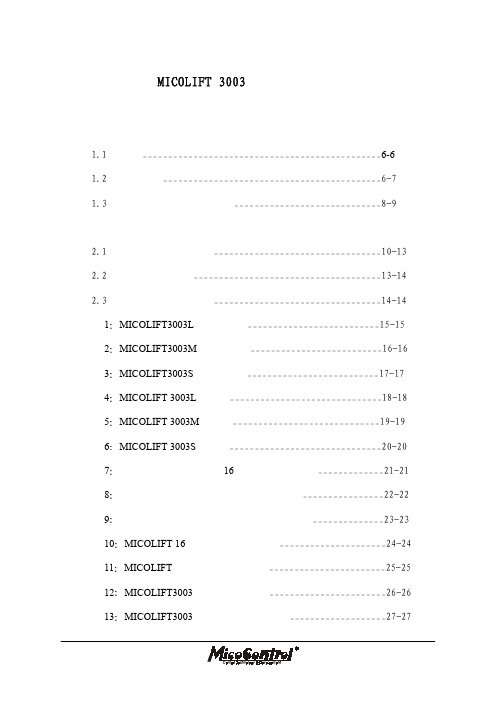
3.5 减速距离的确定_________________________________________56-56 第四章 003B 调试器使用说明______________________________________57-57
4.1 楼层显示_______________________________________________58-58 4.1_____________________________58-58 4.1.2 坚显示方式___________________________________________58-58 4.2 调试菜单_______________________________________________59-59 4.2.1 调试菜单首页_________________________________________59-59 4.2.2 调试菜单主界面_______________________________________59-60 4.2.3 调试主菜单界面_______________________________________60-62 4.3 菜单描述_______________________________________________62-63 4.3.1 配置菜单_____________________________________________63-67 4.3.2 时间设置菜单_________________________________________67-69 4.3.3 基站的设定___________________________________________69-71 4.3.4 呼梯菜单_____________________________________________71-73 4.3.5 输入输出菜单_________________________________________73-74 4.3.6 开门菜单_____________________________________________74-75 4.3.7 故障记录菜单_________________________________________76-77 4.3.8 密码菜单_____________________________________________77-78 4.3.9 脉冲监控菜单_________________________________________78-80 4.3.10 输入选择菜单_________________________________________81-81 第五章 003 系列液晶显示器说明 5.1 规格___________________________________________________82-82 5.1.1 型号说明_____________________________________________82-82
阿尔法拉瓦尔SaniMidget Retractor旋转喷头商品介绍说明书

rger ducts,channels,cyclones,chambers,complexed reactors,vent lines and other critical areas in process lines can therefore be cleaned to the highest standards with no manual or semi-automated interference,and preventing any product carry over or hazardous incidents.Benefits•More uptime due to40%faster cleaning than static spray balls •Dynamic cleaning performance•Cost-effective cleaning with up40%savings in water and cleaning media costsStandard designThe Alfa Laval SaniMidget Retractor is available with two styles of retracting mechanisms:•Pneumatic-driven mechanism using air pressure to extend and retract the cleaning head•Media-driven mechanism using the pressure of the cleaning media to extend the cleaning head and an integrated spring to retract it An optional ATEX version for use in potentially explosive areas is available.Working principleTheflow of the cleaning media causes the head of the AlfaLaval SaniMidget Retractor to rotate,and the fan-shaped jets lay out a swirling pattern throughout the tank or reactor.This generatesthe wetting/impact needed for the efficient removal of the residual product;the cascadingflow covers all internal surface of the vessel, duct or air vent.CertificatesQ-doc and ATEXTECHNICAL DATAFlow rate:7.3m³/h at3bar Standard strokes:100,150or250mm Lubricant Self lubricating with cleaning mediaWetting radius:Max. 3.5m Impact cleaning radius:Max.Effective1.7mAir qualityClean,filtered:max.40µm Dry,dew point:max.10°C Installation:Please contact Alfa Laval for installation of tank cleaning machinePHYSICAL DATAMaterialsProduct area:316L(UNS S31603),PEEK* Non-product area:304(UNS S30400),POM Sealing:EPDM**FDA compliance21CFR§177SurfacefinishProduct contact surfaces:Ra0.8µm Non product contact parts:Ra1.6µmTemperatureMax.working temperature:95°C Max.ambient temperature:150°CWeight:See reverse page Options-MaterialsA.Alternative sealing component material,FFKM*B.Positioning sensors,which generate digital signals at the fully retracted or fully extended positionsC.3.1.certificate for metallic parts available upon request.Product contact parts only*FDA compliance21CFR§177CautionAvoid hydraulic shock,hard and abrasive particles in the cleaning liquid,as this can cause increased wear and/or damage of internal mechanisms.In general,afilter in the supply line is recommended.Do not use for gas evacuation or air dispersion.For steaming we refer to the manual.PressureRecommended operating cleaningfluid pressure:3bar Cleaningfluid pressure when retracted:Pressureless Air supply pressure:2-5barPressure:Air to Air(AA)Cleaningfluid pressure:1-5bar Tank pressure:*No Pressure Air supply pressure:2-5bar Purging possible:Not supported-contact Alfa LavalPressure:Air to Spring(AS)Cleaningfluid pressure:1-5bar Tank pressure:*No Pressure Air supply pressure:2-5bar Purging possible:Not supported-contact Alfa LavalPressure:Media to Spring(MS)Cleaningfluid pressure:2½-5bar Tank pressure:*No Pressure Purging possible:Not supported-contact Alfa Laval *For applications with other pressure,please contact Alfa Laval for supportSprayPattern270°upQuali fication DocumentationDocumentation speci ficationEquipment Documentation includes:Q-doc-EN 1935/2004DoC-EN 10204type 3.1inspection Certi ficate and DoC -FDA DoC-GMP EC 2023/2006DoC -EU 10/2011DoC -ADI DoC -QC DoCATEX approved machine for use in explosive atmospheres Catagory 1for installation in zone 0/20in accordance with Directive 2014/34/EUATEX marking for the equipment SaniMidget Retractor:II 1G Ex h IIC 85°C…188°C Ga ATEXII 1D Ex h IIIC T85°C…T150°C DaFlowRate845671093F l o w r a t eInlet pressureA/S =Air/spring version A/A =Air/air version M/S =Media/spring versionCleaningRadius4123T h r o w l e n g h tInlet pressureA: Wetting - B: Impact cleaningDimensions (mm)Pneumatic driven Stroke A B C D E F G H Weight 10010040950913358.5ø76.1ø857 5.6kg 15015050965918358.5ø76.1ø857 6.3kg 25025070995928358.5ø76.1ø8577.4kgMedia driven version +Pneumatic driven version with Spring return Stroke A B C D E F G H Weight 10010047957913358.5ø76.1ø857 5.6kg15015060975918358.5ø76.1ø857 6.3kg 250250869111928358.5ø76.1ø8577.4kg1Connections1.Tank connections2.Cleaning media 1"Clamp ISO 28523.Air supply -pneumatic driven only ISO 228-G 1/84.OptionMagnetic sensor5.Adjustable valve -media driven onlyTank Connection 3”Clamp ISO 28523”ISO 2037/US DN80DIN 11.850Alfa Laval reserves the right to change specifications without prior notification.How to contact Alfa Laval Contact details for all countriesare continually updated on our website.Please visit to access the information direct.A l f a L a v a l i s a t r a d e m a r k r e g i s t e r e d a n d o w n e d b y A l f a L a v a l C o r p o r a t e AB . E S E 00334e n 2108。
M1A3P250-VQ144中文资料(Actel)中文数据手册「EasyDatasheet - 矽搜」

速度等级
FG =细间距球栅阵列(1.0 mm间距)
F =比标准慢20%*
空白=标准 比标准快1 = 15%
比标准快2 = 25%
ProAS IC 3器 件
= A3P015系统15000门 A3P030 = 30,000个系统门 A3P060 = 60,000个系统门
A3P125 = 125000个系统门 A3P250 = 25万系统门 A3P400 = 40万系统门
1 - ProASIC3器件系列简介
概述
ProASIC3中,Actel以Flash FPGA第三代家族,提供性能,密度和
超出ProASIC功能
PLUS® 家人.非易失性闪存技术使ProASIC3
设备是安全,低功耗,单芯片解决方案,上电即行(LAPU)优势.ProASIC3再编程,提供时间将
产品推向市场好处在一个ASIC级单位成本.
I =工业(
–40°C至+ 85°C环境温度)
PP =预生产
ES =工程样品(室温仅)
无铅封装
空白=标准包装 G =符合RoHS标准(绿色)包装
封装类型
零件号
QN =四方扁平封装无引线(0.6至0.5mm节距)
VQ =非常薄型四方扁平封装(0.5 mm间距)
TQ =薄型四方扁平封装(0.5 mm间距) PQ =塑料四方扁平封装(0.5 mm间距)
169
1.0 1.45
FG256 17 × 17
289
1.0 1.60
FG484 23 × 23
529
1.0 2.23
II
v1.0
芯片中文手册,看全文,戳
ProASIC3订购信息
闪存ProASIC3系列FPGA
A-T Controls 8R系列3部分三角电流控制阀门说明说明书

8RM-20151024Copyright 2013 A-T Controls, Inc.SERIES 8R 3-PieceTriac 8R Series 3-Piece Ball Valves arethe finest quality 3-piece valves on the market.The high quality investment castings feature a fully machined bore. The superior live-loaded packing system is accomplished with Belleville washers, “V” ring packing and a unique primary pyramidal stem seal. This advanced sealing system provides protection against stem leaks experienced by ordinary ball valves.See automated data sheets for pre-sized assembliesPneumaticElectricCincinnati, Ohio FAX (513) 247-5462********************Lock Saddle Belleville WasherGlandChevron Packing Pyramidal (45°)Stem & Stem sealRTFE seats are standard, but various options are available for seat materials. The 50/50 STFE seat option is excellent for services that call for highertemperatures and more difficult applications including steam.Call us for details.9955 International Blvd.Cincinnati, Ohio PHONE (513) 247-5465FAX (513) 247-5462********************A-T Controls reserves the right to change product designs and technical/dimensional specifications without notice.High Performance, Regular Port 3-Piece Ball ValveISO 5211 Mounting Pad1500 & 2000 psi WOG by size 1/4” to 2-1/2”TEMPERATURE IN °F (°C)P R E S S U R E I N P S I GPRESSURE IN BAR2000(-18)-20(-28)0100(38)600400800500(260)(149)200300(93)400(204)13.8027.841.455.2110.368.982.796.5124.1151.7137.9600(316)Pressure vs. Temperature Chartmaterial, consult factoryTHREADED ENDENDSOCKET WELDBUTT WELDENDNOTE: Dotted line shows the rating for valve body. Solid line shows the rating for valve seat. Both ratings need to be considered when determining the limitation of the valve for specific application. Consult factory for other seat materials.8RDA-20151024Copyright 2013 A-T Controls, Inc.SERIES 8R 3-PieceCincinnati, Ohio FAX (513) 247-5462********************Other options available - call for detailsActuators are sized based on clean/clear fluid.Lock Saddle Belleville WasherGlandChevron Packing Pyramidal (45°)Stem & Stem seal8RSR-20151024Copyright 2013 A-T Controls, Inc.Actuators are sized based on clean/clear fluid.SERIES8R3-PieceCincinnati, Ohio 45246FAX (513) 247-5462******************** Lock SaddleBelleville WasherGlandChevron PackingPyramidal (45°)Stem & Stem sealSee valve part numbermatrix for complete partnumber and options.SAMPLE PART #Valve SeriesValve SizeSeat MaterialEnd ConnectionTRIAC Actuator SeriesActuator SizeSpring ReturnSolenoidLimit SwitchCarbon Steel8RC-TX-050/2R2S-XX8REL-20151024Copyright 2013 A-T Controls, Inc.SAMPLE PART #Other options available - call for detailsActuators are sized based on clean/clear fluid.NOTE: Heater and thermostat standard (2) auxiliary switches standardLock Saddle Belleville WasherGlandChevron Packing Pyramidal (45°)Stem & Stem sealCincinnati, Ohio FAX (513) 247-5462********************Manual and automated valve assemblies for gas burner management applicationsand safety shutoffVarious Seat MaterialsPTF E, RTF E, 50/50 STF E, 25% CTF E, Delrin,PEEK, UHMWPE, TFM-1600Operator OptionsQuarter-turn Gear OperatorsSpring Return “Deadman” HandlesOval handles, TEE HandlesSpecials and SolutionsSteam JacketsStem ExtensionsV-ported Control ValvesMulti-port Valve SolutionsFugitive Emissions Bonnets (TSM’s)Oxygen CleaningLockout BracketsVented Balls“No Play” Mounting Kits• FM ApprovedValves and AssembliesSpecial SeatsBalls and Seal DesignsFloor MountedDamper DrivesFusible LinkAssembliesLockoutMounting KitsSpecialMulti-Port ValvesSteam JacketedValvesLimit SwitchesMounted on Manual Valves180º ActuatorsStem ExtensionsDual ValveAssembliesCincinnati, Ohio 45246FAX (513) 247-5462********************。
3KC ATC6300 自动转换控制器 设备手册说明书
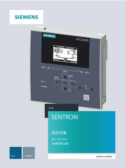
4.5 4.5.1 4.5.2
ATC6300 的显示页面....................................................................................................30 显示页面说明 ...............................................................................................................30 滚动显示页面 ...............................................................................................................41
2.1
ATC6300 自动转换控制器的属性 ..................................................................................15
2.2
兼容的西门子 SENTRON 开关设备.................................................................................17
3.3
电压控制 ......................................................................................................................22
4 产品描述 .........................................................................................................................................25
艾特镀金磨砂电路保护元件数据手册说明书
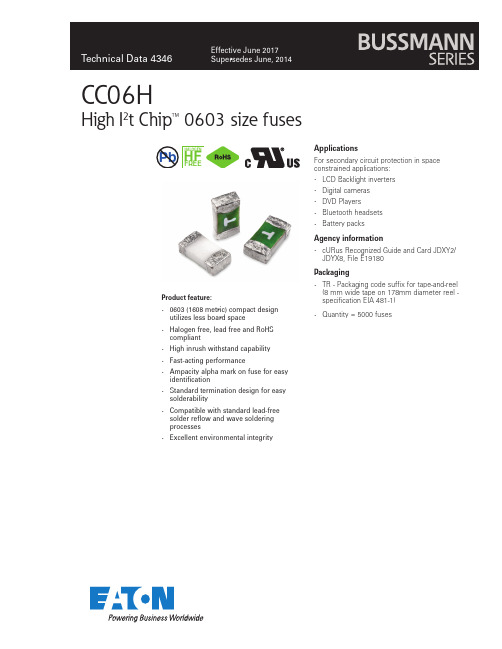
Product feature :•0603 (1608 metric) compact design utilizes less board space•Halogen free, lead free and RoHS compliant•High inrush withstand capability •Fast-acting performance•Ampacity alpha mark on fuse for easy identification•Standard termination design for easy solderability•Compatible with standard lead-free solder reflow and wave soldering processes•Excellent environmental integrityApplicationsFor secondary circuit protection in spaceconstrained applications:• LCD Backlight inverters • Digital cameras • DVD Players • Bluetooth headsets •Battery packsAgency information•cURus Recognized Guide and Card JDXY2/JDYX8, File E19180Packaging•TR - Packaging code suffix for tape-and-reel (8 mm wide tape on 178mm diameter reel -specification EIA 481-1)•Quantity = 5000 fusesCC06HHigh I 2t Chip™ 0603 size fuses7 014PbTechnical Data 4346Effective June 2017CC06H High I2t Chip™ 0603 size fusesElectrical characteristicsAmp Rating% of Amp Rating Opening Time 1-8A100 4 Hours1-7A2001-60 Seconds1-8A250 5 Seconds Max SpecificationsPart NumberAmpRating5VoltageRating(Vdc)InterruptingRating1, 4(A)Typical ColdResistance2(Ω)TypicalPre-Arcing3(I2t)TypicalVoltageDrop(mV)TypicalPowerDissipation(W)AlphaMarkingAgencyInformation(cURus)CC06H1A132500.250.023100.32B x CC06H1.5A 1.532500.130.072500.38H x CC06H2A232500.0680.141700.38K x CC06H2.5A 2.532500.050.251550.38L x CC06H3A332500.0350.301300.38O x CC06H3.5A 3.532500.0230.501000.35R x CC06H4A432500.020.81100.45S x CC06H5A532500.013 1.6950.48T x CC06H6A632500.0076 2.6800.48V x CC06H7A732500.0056 3.3800.56X x CC06H8A832/2450/800.0040 4.5750.60Z x1.DC Interrupting Rating (measured at rated voltage, time constant of less than 50 microseconds, battery source).2.DC Cold Resistance are measured at <10% of rated current in ambient temperature of 20°C -FOR REFERENCE ONLY - CONTROLLED VALUES HELD BY PLANT AND SUBJECT TO CHANGE WITHOUT NOTICE.3.Typical Pre-arcing I2t are measured at rated DC voltage, 10Incurrent (not to exceed interrupting rating).4.The insulation resistance after breaking capacity test is higher than 0.1MΩ when measured by 2X rated voltage.5.Device designed to carry rated current for 4 hours minimum. An operating current 80% or less of rated current is recommended,with further design derating required at elevated ambient temperature. See Temperature Derating Curve on next page./el ectronics23Technical Data 4346Effective June 2017CC06HHigh I 2t Chip™ 0603 size fuses Time-current curves — average melt/el ectronics4Technical Data 4346Effective June 2017CC06HHigh I 2t Chip™ 0603 size fusesI 2t vs. time curvesI 2t (A 2s )5Technical Data 4346Effective June 2017CC06HHigh I 2t Chip™ 0603 size fuses I 2t vs. current curvesI 2t (A 2s )/el ectronics6Technical Data 4346Effective June 2017CC06HHigh I 2t Chip™ 0603 size fusesT emperature derating curve Product characteristicsOperating temperature -40 °C to +85 °C , with proper derating factor applied Storage temperature -40 °C to +85 °CLoad humidity MIL-STD-202G, Method 103B (1000 hr @ +85 °C / 85% RH & 10% rated current)Moisture resistance MIL-STD-202, Method 106E (50 cycles)Thermal shock MIL-STD-202, Method 107D (-65 °C to +125 °C, 100 cycles)Vibration testMIL-STD-202, Method 204D, Test Condition D (10-2,000 Hz)Mechanical shock resistance MIL-STD-202, Method 213B (3000 G / 0.3 ms)Salt spray resistance MIL-STD-202, Method 101, Test Condition B (48 h ou r exposure)Insulation resistance The insulation resistance after breaking capacity test is higher than 0.1 M Ω when measured by 2X rated voltage SolderabilityJ-STD-002C Method B1 (Dip and Look Test), Method G1 (Wetting Balance Test), Method D (Resistance to Dissolution / Dewetting of Metalization)Resistance to soldering heat MIL-STD-202, Method 210F (Solder dip +260 °C, 60 seconds / Solder Iron +350 °C, 3-5 seconds)High temperature life test MIL-STD-202G, Method 108A (1000 Hours @ +70 °C & 60% rated current)Resistance to solventsMIL-STD-202, Method 215KDimensions - mm (in)Drawing not to scale.0.47 ± 0.08Pad layoutA 0B 0D 0E 1E 2F G P 0P 1P 2T W 0.95±0.051.80±0.051.50+0.10,-0.01.75±0.106.25±0.303.50±0.050.75min.4.00±0.104.00±0.102.00±0.050.060±0.058.00±0.20*Tolerance for peak profile temperature (T p ) is defined as a supplier minimum and a user maximum.** Tolerance for time at peak profile temperature (t p ) is defined as a supplier minimum and a user maximum.Solder reflow profileTechnical Data 4346Effective June 2017CC06HHigh I 2t Chip™ 0603 size fusesLife Support Policy: Eaton does not authorize the use of any of its products for use in life support devices or systems without the express written approval of an officer of the Company. Life support systems are devices which support or sustain life, and whose failure to perform, when properly used in accordance with instructions for use provided in the labeling, can be reasonably expected to result in significant injury to the user.Eaton reserves the right, without notice, to change design or construction of any products and to discontinue or limit distribution of any products. Eaton also reserves the right to change or update, without notice, any technical information contained in this bulletin.EatonElectronics Division 1000 Eaton Boulevard Cleveland, OH 44122United States/electronics © 2017 EatonAll Rights Reserved Printed in USAPublication No. 4346 BU-SB14476 June 2017Eaton is a registered trademark.All other trademarks are property of their respective owners.。
用哈兹列特法生产出性能优良3003-2产品介绍
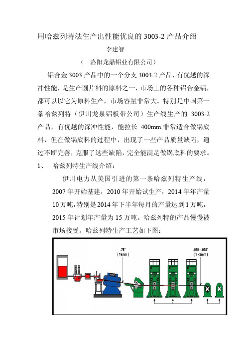
用冲性都可条产料过不1、哈兹列铝合金性能,是可以以它哈兹列特品,有优,但在做不断完善 哈兹列伊200710万2015市场接特法生( 金3003产是生产圆片它为原料特(伊川优越的深做锅底料善,克服列特生产伊川电力年开始基吨,特别年计划年接受。
哈生产出性李洛阳龙鼎产品中的一片料的原料生产,市川龙泉铝深冲性能,料的过程中了这些缺产线介绍从美国基建,20是2014年产量为哈兹列特性能优良李建智鼎铝业有一个分支原料之一市场容量铝板带公司,能拉长中,出现缺陷,完全绍:引进的第010年开年下半年为15万吨特生产工艺良的3003限公司)支3003-2一,市场上量非常大司)生产长400mm 现了一些全能满足第一条哈开始试生产年每月的吨。
哈兹艺如下图3-2产品2产品,有上的各种大。
特别是产线生产m,非常适些产品质量足做锅底哈兹列特产,2014的产量达到列特的产图:品介绍有优越的种铝合金锅是中国第产的300适合做锅量缺陷,底料的要求特生产线4年年产到1万吨产品慢慢的深锅,第一3-2锅底通求。
线,产量吨,慢被2、2.1传统的从以轧法的流程大 哈兹列1 通过不断我们把的热轧工以上的工的据头尾大大简化列特产品过微合金化断对300把这种产3003及合金牌号30033003-2 3003-2具以上,深工艺如下工艺图可尾和表面化,节能品的开发化来优化03成分进产品起名3003-2成Si0.6 0.14具有一下深冲力比下图:可以看出,面车铣、二能效果显著发化产品性进行优化为3003成分对比Fe 0.70.32 下优点,比3003要,哈兹列二次加热著。
性能,形成化,形成-2。
比如下:Cu 0.05-0.20.06 O 态延伸要小,能特生产法热、热粗成独特的成自己独特Mn 20 1.0-10.70 伸率能够满足深冲法省去了粗轧等过程的产品。
特的成分Ti .5 0.02够达到3冲机冲力了热程, 分,23 0%力的2.23、3.12 非常优 3003-2对策进1 表面有划造成过高温需要,晶优越的深3003-2产底料的好2产品在进行消除有黑丝条成的,另一温退火引起晶粒度能深冲性能产品深冲好材料。
3M电工产品目录说明书
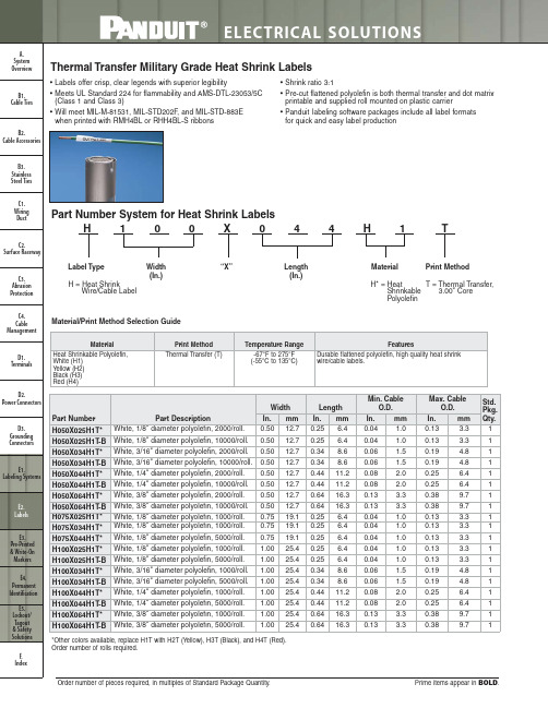
0.04 1.0
0.06 1.5
0.06 1.5
0.08 2.0
0.08 2.0
0.13 3.3
0.13 3.3
0.04 1.0 0.04 1.0
0.04 1.0
0.04 1.0
0.04 1.0
0.06 1.5
0.06 1.5
0.08 2.0
0.08 2.0
Width In. mm 0.50 12.7 0.50 12.7 0.50 12.7 0.50 12.7 0.50 12.7 0.50 12.7 0.50 12.7 0.50 12.7 0.75 19.1 0.75 19.1 0.75 19.1 1.00 25.4 1.00 25.4 1.00 25.4 1.00 25.4 1.00 25.4 1.00 25.4 1.00 25.4 1.00 25.4
*Other colors available, replace H1T with H2T (Yellow), H3T (Black), and H4T (Red). Order number of rolls required.
Length In. mm 0.84 21.3 1.65 41.9 0.25 6.4 0.34 8.6 0.44 11.2 0.25 6.4 0.25 6.4 0.34 8.6 0.34 8.6 0.44 11.2 0.44 11.2 0.64 16.3 0.64 16.3 0.84 21.3 0.84 21.3 1.65 41.9
Min. Cable O.D.
In.
mm
0.170 4.3
C4. Cable Management
Material/Print Method Selection Guide
Littelfuse 电源保护器 LC03-3.3 数据手册说明书
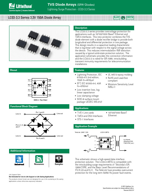
© 2017 Littelfuse, Inc.Specifications are subject to change without notice.Revised: 05/12/17DescriptionFeaturesApplicationsThis LC03-3.3 series provides overvoltage protection for applications such as 10/100/1000 BaseT Ethernet and T3/E3 interfaces. This new protector combines the TVS diode element with a diode rectifier bridge to provide both longitudinal and differential protection in one package. This design results in a capacitive loading characteristic that is log-linear with respect to the signal voltage across the device. This reduces intermodulation (IM) distortion caused by a typical solid-state protection solution. The application schematic provides the connection information and the LC03-3.3 is rated for GR-1089, intra-building transient immunity requirements for telecommunication installations.PinoutFunctional Block Diagram• Lightning Protection, IEC 61000-4-5 2nd edition, 150A (t p =8/20µs)• EFT , IEC 61000-4-4, 40A (t p =5/50ns)• Low insertion loss, log-linear capacitance • Low clamping voltage • SOIC-8 surface mount package (JEDEC MS-012)• UL 94V-0 epoxy molding • RoHS and Lead-free compliant• Moisture Sensitivity Level (MSL -1)• T1/E1 Line cards • T3/E3 and DS3 Interfaces • STS-1 Interfaces• 10/100/1000 BaseT EthernetSOIC-8 (Top View)Pin 4 and 5and 7Line outLine outLine in Line inLife Support Note:Not Intended for Use in Life Support or Life Saving ApplicationsThe products shown herein are not designed for use in life sustaining or life saving applications unless otherwise expressly indicated.Application ExampleThis schematic shows a high-speed data interfaceprotection solution. The LC03-3.3BTG is compatible with the intra-building surge requirements of Telcordia’s GR-1089-CORE, and the Basic Level Recommendations of ITU K.20 and K.21. The TeleLink fuse provides overcurrent protection for the long term 50/60 Hz power fault events., , etc.)LC03-3.3 Series 3.3V 150A Diode Array© 2017 Littelfuse, Inc.Specifications are subject to change without notice.Revised: 05/12/17Absolute Maximum RatingsElectrical Characteristics (T OP = 25°C)Thermal InformationCAUTION: Stresses above those listed in “Absolute Maximum Ratings” may causepermanent damage to the device. This is a stress only rating and operation of the device at these or any other conditions above those indicated in the operational sections of this specification is not implied.Figure 2: Current Derating CurveFigure 1: Non-repetitive Peak Pulse Current vs. PulseTime© 2017 Littelfuse, Inc.Specifications are subject to change without notice.Revised: 05/12/17Figure 4: Clamping Voltage vs. Peak Pulse CurrentFigure 6: Forward Voltage vs. Forward CurrentFigure 3: 8/20 µs Pulse WaveformFigure 5: Capacitance vs. Reverse Voltage0%10%20%30%40%50%60%70%80%90%100%110%0.0 5.0 10.0 15.0 20.0 25.0 30.0Time (μs)P e r c e n t o f I P PLine to GroundLine to Line 0123456789100.00.51.01.52.02.53.0C a p a c i t a n c e (p F )Bias Voltage (V)Line to LineLine to Ground0246810121416180102030405060708090100C l a m p V o l t a g e -V C (V )Peak Pulse Current-I PP (A)12345670102030405060708090100Forward Current (A)F o r w a r d V o l t a g e (V )Ground-to-LineSoldering Parameters© 2017 Littelfuse, Inc.Specifications are subject to change without notice.Revised: 05/12/17Part Numbering SystemProduct CharacteristicsOrdering InformationLC033.3B T GSeries Working VoltagePackage T= Tape & ReelG= Green – B = SOICPart Marking SystemPackage Dimensions — Mechanical Drawings and Recommended Solder Pad OutlineFirst Line: Part number Second Line: Date codeF LLC03-3.3XXXXXXXX1. All dimensions are in millimeters2. Dimensions include solder plating.3. Dimensions are exclusive of mold flash & metal burr.4. Blo is facing up for mold and facing down for trim/form, i.e. reverse trim/form.5. Package surface matte finish VDI 11-13.Embossed Carrier Tape & Reel Specification — SOIC PackageDisclaimer Notice - Information furnished is believed to be accurate and reliable. However, users should independently evaluate the suitability of and test each product selected for their own applications. Littelfuse products are not designed for, and may not be used in, all applications. Read complete Disclaimer Notice at /disclaimer-electronics .。
EAA 3003 EAA 3003 PRIMACOR
EAA 3003产品说明EAA 3003简介:PRIMACOR 3003共聚物是一种乙烯丙烯酸共聚物,是陶氏专门设计的一种材料,在挤出涂覆和挤出层压中作为一种粘合剂层或是密封剂层。
PRIMACOR 3003 特性:优异的拉伸性能和边缘稳定性优异的感官性能优异的韧性和强度卓越的耐环境应力开裂性能和耐包装内容物性能优异的热封性能和热粘性能与金属、纸张和PE底材具有优异的粘结力对水分不敏感PRIMACOR EAA 3003应用领域:软质包装复合材料液体包装纸板复合材料EAA 3003产品物性:产品说明PRIMACOR™ 3003共聚物是一种乙烯丙烯酸共聚物,是陶氏专门设计的一种材料,在挤出涂覆和挤出层压中作为一种粘合剂层或是密封剂层。
PRIMACOR 3003共聚物具有以下特性:∙优异的拉伸性能和边缘稳定性∙优异的感官性能∙优异的韧性和强度∙卓越的耐环境应力开裂性能和耐包装内容物性能∙优异的热封性能和热粘性能∙与金属、纸张和PE底材具有优异的粘结力∙对水分不敏感应用领域:∙软质包装复合材料∙液体包装纸板复合材料符合以下法规要求:∙美国食品和药品管理局(U.S. FDA) 21 CFR 177.1310(b) ∙欧盟(EU) No 10/2011请查阅法规以获取详尽资料。
总体材料状态∙已商用:当前有效供货地区∙欧洲∙亚太地区机构评级∙EU No10/2011∙FDA 21 CFR 177.1310(b)形式∙颗粒料加工方法∙挤压层涂法物理性能额定值单位制测试方法比重0.935 g/cm³ASTM D792, ISO 1183 熔流率 2(190°C/2.16 kg)7.8 g/10 min ASTM D1238, ISO 1133 共聚单体含量 3 6.5 % Internal Method机械性能额定值单位制测试方法拉伸模量 - 2% 正割130 MPa ASTM D638, ISO 527-2抗张强度ASTM D638, ISO 527-2屈服7.50 MPa断裂18.0 MPa伸长率 (断裂) 590 % ASTM D638, ISO 527-2薄膜额定值单位制测试方法始封温度 490.0 °C Internal Method热性能额定值单位制测试方法维卡软化温度90.0 °C ISO 306/A溶融温度(DSC)100 °C Internal Method挤出额定值单位制测试方法熔体温度260 到 290 °C内缩量 5(290°C)45.7 mm Internal Method最小涂层重量(290°C)8.0 g/m²Internal Method 备注东莞友信塑胶EAA常用型号简介:产品型号列表。
TT Electronics LRF3W系列低功耗3W晶体管电阻器商品说明书

Low temperature storage -65°C for 100 hours
Shelf life test Room temp. for 12 months
Leach resistance Solder dip at 250°C
Note: Full AEC-Q200 qualification applies to ohmic values ≥R02
© TT Electronics plc
BI Technologies IRC Welwyn
/resistors 05.23
© TT Electronics plc
BI Technologies IRC Welwyn
/resistors 05.23
Low Value 3W Chip Resistors LRF3W Series
Performance Data
AEC-Q200
Test
All Pb-free parts comply with EU Directive 2011/65/EU amended by (EU) 2015/863 (RoHS3)
Electrical Data
LRF3W
Power rating at 70°C
W
3
Resistance range
Ω
R003 to R10
Processing
LRF3W chips are placed on the termination pads with the actual resistor element mounted face down. For reflow of LRF3W parts,a solder paste thickness of not less than 100µm is recommended.
- 1、下载文档前请自行甄别文档内容的完整性,平台不提供额外的编辑、内容补充、找答案等附加服务。
- 2、"仅部分预览"的文档,不可在线预览部分如存在完整性等问题,可反馈申请退款(可完整预览的文档不适用该条件!)。
- 3、如文档侵犯您的权益,请联系客服反馈,我们会尽快为您处理(人工客服工作时间:9:00-18:30)。
Email: info@
In keeping with our ongoing policy of product evolvement and improvement, the above specification is subject to change without notice.
ISO9001: 2000 Registered - Registration number 6830/2
The ACTR3003/345.0/QCC4A is a true one-port, surface-acoustic-wave (SAW ) resonator in a surface-mount ceramic QCC4A case. It provides reliable, fundamental-mode, quartz frequency stabilization i.e. in transmitters or local oscillators operating at 345.000 MHz.
1.Package Dimension (QCC4A)
3.Equivalent LC Model and Test Circuit
4.Typical Application Circuits
1) Low-Power Transmitter Application 2) Local Oscillator Application
Pin
Configuration 1 Input / Output 3 Output / Input 2/4
Case Ground
Sign Data (unit: mm)
Sign Data (unit: mm)
A 1.2 D 1.4
B 0.8 E 5.0 C
0.5
F
3.5
Issue : 1 C1
Email: info@
In keeping with our ongoing policy of product evolvement and improvement, the above specification is subject to change without notice.
ISO9001: 2000 Registered - Registration number 6830/2
5.Typical Frequency Response
6.Temperature Characteristics
7.Performance
7-1.Maximum Ratings
Rating
Value
Units
CW RF Power Dissipation 0 dBm DC Voltage Between Terminals ±30V VDC Case Temperature -40 to +85 °C Soldering Temperature
+250
°C
7-2.Electronic Characteristics
Characteristic
Sym
Minimum
Typical
Maximum
Units
Absolute Frequency
f C 344.925
345.075
MHz Centre Frequency
(+25 °C) Tolerance from 345.000 MHz
∆f C ±75 kHz Insertion Loss I L 1.5 2.2 dB Unloaded Q Q U 10,020 Quality Factor
50 Ω Loaded Q Q L 1,600 Turnover Temperature
T 0 25 55 C Turnover Frequency
f 0 f C kHz Temperature Stability
Frequency Temperature Coefficient
FTC 0.032 ppm/°C 2 Frequency Aging Absolute Value during the First Year |fA | ≤10 ppm/yr DC Insulation Resistance Between Any Two Terminals
1.0 M Ω Motional Resistance
R M 19 29 Ω Motional Inductance L M 87.8796 µH Motional Capacitance C M 2.4241 fF RF Equivalent RLC Model
Shunt Static Capacitance C 0
2.25
2.55
2.85
pF
Email: info@
In keeping with our ongoing policy of product evolvement and improvement, the above specification is subject to change without notice.
ISO9001: 2000 Registered - Registration number 6830/2
i CAUTION: Electrostatic Sensitive Device. Observe precautions for handling!
1. The centre frequency, f C , is measured at the minimum IL point with the resonator in the 50Ω test system.
2. Unless noted otherwise, case temperature T C = +25°C±2°C.
3. Frequency aging is the change in f C with time and is specified at +65°C or less. Aging may exceed the specification
for prolonged temperatures above +65°C. Typically, aging is greatest the first year after manufacture, decreasing in subsequent years.
4. Turnover temperature, T 0, is the temperature of maximum (or turnover) frequency, f 0. The nominal frequency at any
case temperature, T C , may be calculated from: f = f 0 [1 - FTC (T 0 - T C )2
].
5. This equivalent RLC model approximates resonator performance near the resonant frequency and is provided for
reference only. The capacitance C 0 is the measured static (non-motional) capacitance between the two terminals. The measurement includes case parasitic capacitance.
6. Derived mathematically from one or more of the following directly measured parameters: f C , IL, 3 dB bandwidth, f C
versus T C , and C 0.
7. The specifications of this device are based on the test circuit shown above and subject to change or obsolescence
without notice.
8. Typically, equipment utilizing this device requires emissions testing and government approval, which is the
responsibility of the equipment manufacturer.
9. Our liability is only assumed for the Surface Acoustic Wave (SAW) component(s) per se, not for applications,
processes and circuits implemented within components or assemblies.。
