TIPL761A中文资料
铱星全球通信设备说明书
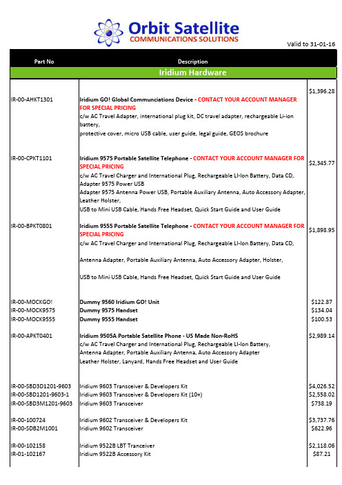
Valid to 31‐01‐16DescriptionIridium Hardware$1,396.28 IR‐00‐AHKT1301Iridium GO! Global Communciations Device ‐ CONTACT YOUR ACCOUNT MANAGERFOR SPECIAL PRICINGc/w AC Travel Adapter, international plug kit, DC travel adapter, rechargeable Li‐ionbattery,protective cover, micro USB cable, user guide, legal guide, GEOS brochureIR‐00‐CPKT1101Iridium 9575 Portable Satellite Telephone ‐ CONTACT YOUR ACCOUNT MANAGER FOR$2,345.77 SPECIAL PRICINGc/w AC Travel Charger and International Plug, Rechargeable LI‐Ion Battery, Data CD,Adapter 9575 Power USBAdapter 9575 Antenna Power USB, Portable Auxiliary Antenna, Auto Accessory Adapter,Leather Holster,USB to Mini USB Cable, Hands Free Headset, Quick Start Guide and User GuideIR‐00‐BPKT0801Iridium 9555 Portable Satellite Telephone ‐ CONTACT YOUR ACCOUNT MANAGER FOR$1,898.95 SPECIAL PRICINGc/w AC Travel Charger and International Plug, Rechargeable LI‐Ion Battery, Data CD,Antenna Adapter, Portable Auxiliary Antenna, Auto Accessory Adapter, Holster,USB to Mini USB Cable, Hands Free Headset, Quick Start Guide and User GuideIR‐00‐MOCKGO!Dummy 9560 Iridium GO! Unit$122.87 IR‐00‐MOCK9575Dummy 9575 Handset$134.04 IR‐00‐MOCK9555Dummy 9555 Handset$100.53 IR‐00‐APKT0401 Iridium 9505A Portable Satellite Phone ‐ US Made Non‐RoHS$2,989.14 c/w AC Travel Charger and International Plug, Rechargeable LI‐Ion Battery,Antenna Adapter, Portable Auxiliary Antenna, Auto Accessory AdapterLeather Holster, Lanyard, Hands Free Headset and User GuideIR‐00‐SBD3D1201‐9603Iridium 9603 Transceiver & Developers Kit$4,026.52 IR‐00‐SBD1201‐9603‐1Iridium 9603 Transceiver & Developers Kit (10+)$2,558.02 IR‐00‐SBD3M1201‐9603Iridium 9603 Transceiver$738.19 IR‐00‐100724 Iridium 9602 Transceiver & Developers Kit$3,737.76 IR‐00‐SDB2M1001Iridium 9602 Transceiver$622.96 IR‐00‐102158Iridium 9522B LBT Tranceiver$2,118.06 IR‐01‐102167Iridium 9522B Accessory Kit$87.21IR‐00‐CLBT1101‐9523Iridium 9523 Core$2,684.34 IR‐00‐LBTDT1101‐9523Iridium 9523 Development & Transceiver Kit$4,026.52 Iridum Go! CablesIR‐01‐GO‐ADAPTCABLE Iridium Go! Adaptor Cable (ex Thailand)$25.00 IR‐01‐W5USB1301Outdoor cable 5M usb‐a to MicroUSB plug$95.77 IR‐01‐WBAT13019560 Battery 3500mAh$134.05 IR‐01‐WBKT1301Bracket Kit ‐ wall mount for 9560$79.82 IR‐01‐WCCS1301Carry Bag with karabiner for 9560 ‐ bagged$70.24 IR‐01‐WACTC1301AC Charger, USB 5V 2.1A, Black, 4 region plugs, Boxed$92.58 IR‐01‐WAUT1301Auto Adaptor, Cig‐lighter plug to USB$35.13 IR‐01‐WCVR13019560 Protective Cover (uses BEA_018_130) with polybag$35.13 IR‐01‐WMUSB1301Cable USB 1.2m USB‐A plug to microUSB plug, thick gauge$22.34 Standard Accessories for 9575 & 9555 Portable PhoneIR‐01‐PHS300IC Iridium AxcessPoint WiFi$325.47 IR‐01‐USBC0801USB‐Mini USB Cable ‐ 9555$65.77 Standard Accessories for 9575 Portable PhoneIR‐01‐BAT31001Rechargeable Li‐ion Battery ‐ 9575$213.70 IR‐01‐H3AA1101Adapter, 9575 Antenna, Power USB$263.03 IR‐01‐H3APU1101Adapter, 9575, Power USB$230.13 IR‐01‐H3HOL1101Leather Holster ‐ 9575$82.19 IR‐01‐H3QS1101Quick Start Guide – printable copies available via IR‐01‐H3UG1101User Guide ‐ 9575$39.46 IR‐01‐H3CD1101Data CD ‐ 9575$13.15 Standard Accessories for 9555 Portable PhoneIR‐01‐BAT41101Rechargeable Hi Capacity Li‐ion Battery ‐ 9555$295.90 IR‐01‐H2UG1002User Guide ‐ 9555 (& 9575)$39.46 IR‐01‐USBC0801USB‐Mini USB Cable ‐ 9555$65.77 IR‐01‐ H2AA0801Antenna Adapter ‐ 9555$115.06 IR‐01‐HOL0801Leather Holster ‐ 9555$82.19 IR‐01‐BAT21101Rechargeable Li‐ion Battery ‐ 9555$197.26 IR‐01‐H2CD0801Data CD ‐ 9555$13.15 PEL‐01‐1300Peli case for 9555$166.37 Standard Accessories for 9575, 9555 & 9505A Portable PhoneIR‐01‐ACTC0701AC Travel Charger $180.83 IR‐01‐IPK0601International Plug Kit $65.77 IR‐01‐AUT0901Auto Accessory Adapter $115.06 IR‐01‐PAA0601Portable Auxiliary Antenna$246.58 IR‐01‐HFHS0601Hands Free Headset, Retractable$36.17 Standard Accessories for 9505A Portable PhoneIR‐01‐RDA0401RS‐232 Adapter for Data Kit ‐ 9505A$164.38 IR‐01‐ADKT0602Data Kit ‐ 9505A$276.15 IR‐01‐PUG0602User Guide ‐ 9505A$39.46 IR‐01‐BAT0602Rechargeable Li‐ion Battery 2800 mAh ‐ 9505A$197.26Standard Accessories for SS9500, SS9505 and 9505A Portable PhonesIR‐01‐AAA0601Auxiliary Antenna Adapter$115.06 IR‐01‐DCD06002CD‐ROM$13.15 Standard Accessories for both SS9505 and 9505A Portable PhonesIR‐01‐SYN7863A Leather Holster for 9505$82.19 IR‐01‐ANT0501Replacement Antenna ‐ 9505/9505A$443.83 Standard Accessories for both SS9500 and SS9505 Portable PhonesIR‐01‐ACDC0601AC/DC Converter ‐ 9500/9505$147.96 IR‐01‐SYN7024A International Plug Kit$65.77 IR‐01‐SYN0039B Auto Accessory Adapter ‐ 9500/9505$115.06 IR‐01‐SYN0060C High Capacity Battery ‐ 9500/9505 $197.26 IR‐01‐SYN8371B Data Kit c/w Data Cable, Tripod Bracket & CD‐ROM ‐ 9505$276.15 IR‐01‐SYN0091A RS‐232 Adapter for Data Kit ‐ 9505 ‐ Whilst Stocks Last$164.38 Iridium SIM CardsIR‐01‐SIM SDL Iridium SIM Card (Includes Activation)IR‐01‐SIM 325 SDL Iridium SIM Card ‐ 325 for Pre‐Paid ServiceIR‐01‐SIM 318 SDL Iridium SIM Card ‐ 318 for Crew Calling Service。
7611型泄漏电流测试仪使用方法
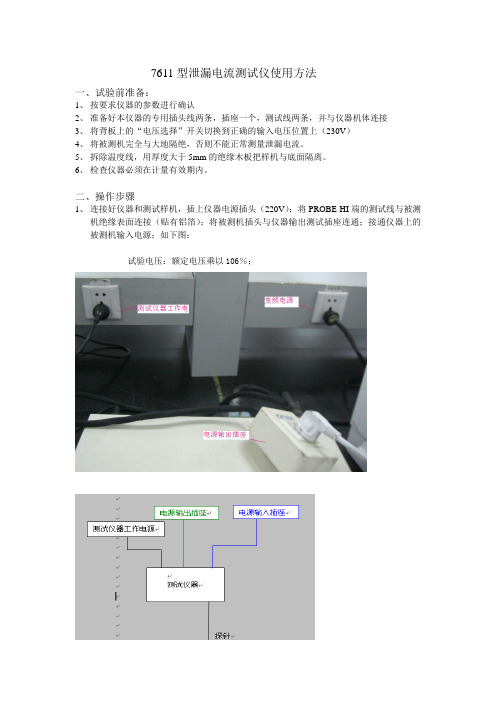
7611型泄漏电流测试仪使用方法一、试验前准备:1、按要求仪器的参数进行确认2、准备好本仪器的专用插头线两条,插座一个,测试线两条,并与仪器机体连接3、将背板上的“电压选择”开关切换到正确的输入电压位置上(230V)4、将被测机完全与大地隔绝,否则不能正常测量泄漏电流。
5、拆除温度线,用厚度大于5mm的绝缘木板把样机与底面隔离。
6、检查仪器必须在计量有效期内。
二、操作步骤1、连接好仪器和测试样机,插上仪器电源插头(220V);将PROBE HI端的测试线与被测机绝缘表面连接(贴有铝箔);将被测机插头与仪器输出测试插座连通;接通仪器上的被测机输入电源;如下图:试验电压:额定电压乘以106%;2、按下面操作调节测试仪器1 TRIP 选择测试量程2 LINE选择正反相、开关机模式3 MD CIRCUIT 选择人体阻抗E4 DELAY设置测试时间5 PROBE选择绝缘模式3、调整参数后如下(下图只是例子):下图模式为:“开机状态反相基本绝缘泄漏电流测试”;“断电状态正相加强绝缘模式”如下:A NEUTRAL 断电模式(A 灯灭,表示样机供电)B REVERSE 反相 (B 灯亮,表示测试反相泄漏电流)C GROUND 接地 (C 灯亮,表示断开接地)AC 亮 ---断电模式正相ABC 亮 ---断电模式反相C 亮 ---开机模式正相BC 亮 ---开机模式反相4、区别插头带/不带有接地端子的测试带有接地端子插头的空调器,可以直接将插头插在测试仪器输出插座上,在测试仪器选择“G-L ”档, 所测的是基本绝缘;选择“P H -L ”档,探针夹住易触及的塑料外壳表面,所测的是加强绝缘;不带有接地端子插头的空调器,可以直接将插头插在测试仪器输出插座上,在测试仪器选择“P H-L”档,探针夹住铜管或钣金件表面,所测的是基本绝缘(原因该插头没有接地线,用P H代替);选择“PH-L”档,探针夹住易触及的塑料外壳表面,所测的是加强绝缘;5、按“TEST”键,开始测试,此时面板右边的“TEST ON”指示灯亮,计时器同时开始计时,显示器显示该测试信息;6、测试完成后,仪器会自动关闭输出,面板右边的绿色“PASS”指示灯亮表示测试结果通过,同时发出一声“哗”的声音。
PRS761A非电量保护装置说明书
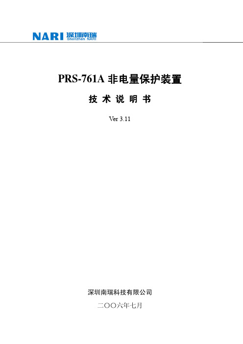
4.1 信号系统.................................................................................................................... 5 4.2 事故分析与过程记录................................................................................................ 5
【附图 1】 装置端子排接线图........................................................................................ 24 【附图 2】 装置前视后视图............................................................................................ 25 【附图 3】 装置安装开孔尺寸图.................................................................................... 26 【附图 4】 本体保护(WB772 板)原理接线图 .......................................................... 27
2 技术参数 ........................................................................................................ 2
士兰微电子 SDH7611AS 说明书

SDH7611AS 说明书
带格式的: 字体: (默认) Arial Rounded MT Bold, (中文) 黑体, 小二, 字体颜色: 绿色, 加宽量 16.55 磅
参 数 范围
650 ±30 2.5 0.6 0.4 30
5 -0.3~6 -40~150 -55~150
2500Biblioteka 单位V V AA mJ
士兰微电子
SDH7611AS 说明书
内置高压启动无VCC电容隔离型LED恒流驱动芯片
描述
SDH7611AS 是一款高精度、低成本的原边反馈 LED 恒流驱动芯片, 应用于反激隔离 LED 照明。
芯片工作在电感电流断续模式,适用于 90Vac~265Vac 输入电压、 5W 输出功率。
SDH7611AS 集成 650V 高压功率 MOS,内置高压启动电路,无需启动 电阻和辅助绕组即能实现芯片的自主供电。
6.0±0.2 0.4~1.27
3.9±0.2
1.8MAX 1.25~1.65
0.15±0.1
1.27BSC 4.9±0.2
注意!
静电敏感器件 操作 ESDS 产品应采取
防护措施
MOS电路操作注意事项:
静电在很多地方都会产生,采取下面的预防措施,可以有效防止 MOS 电路由于受静电放电影响而引起的损坏:
2. 恒流控制
LED输出电流计算公式为:
ILED
=
4
VCS ∗ RCS
∗
NP NS
其中Np是变压器源边匝数;Ns是副边匝数。Vcs为内部基准电压,0.6V。Rcs为电流采样电阻。
3. 保护功能
杭州士兰微电子股份有限公司
http: //
版本号: 共 11 页 第 5 页
MS761中文资料
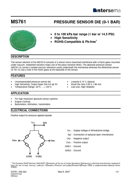
MS761PRESSURE SENSOR DIE (0-1 BAR)• 0 to 100 kPa bar range (1 bar or 14.5 PSI) • High Sensitivity• ROHS-Compatible & Pb-free 1DESCRIPTIONThe sensor element of the MS761A consists of a silicon micro-machined membrane with a Pyrex glass mounted under vacuum. Implanted resistors make use of the piezo-resistive effect. The absolute pressure sensor(MS761-A) carries a sealed vacuum reference cavity underneath the membrane whereas the differential sensor (S-761-D) has a hole in the Pyrex glass at the backside of the sensor.FEATURES• Uncompensated pressure sensor die• High Sensitivity: Output Span 240 mV @ 5V • Temperature Range -40°C …+ 125°C•Linearity 0.15 % (typical)• Small Die Size 2.00 X 1.86 mm •Low cost, High reliabilityAPPLICATION• For high resolution absolute sensor systems • Engine Controls• Barometers, Altimeters, VariometersELECTRICAL CONNECTIONSPositive output for pressure applied topside1The European RoHS directive 2002/95/EC (Restriction of the use of certain Hazardous Substances in electrical and electronic equipment) bans the use of lead, mercury, cadmium, and (PBB) or polybrominated diphenyl ethers (PBDE).GND2GND1 Out + Out -Vs+ : Supply voltage of Wheatstone bridge Epi : Connection of epitaxial layer (membrane) Out- : Negative output Out+ :Positive output GND1 : Ground GND2 : GroundPAD OUTOut+GND1 GND2Important remarks:As the sensing elements are diffused resistances, the voltage applied on the ground pads (GND1 and GND2) has to be lower than the voltage applied on supply voltage pad (Vs+).The epitaxial layer is connected to the Vs+ pin on the dieLAYOUTMS761AMS761DBondable area = 100 x 100 umBondable area = 100 x 100 umFULL SCALE PRESSUREkPa bar mbar PSI atm mm Hg m H2O Inches H2O 100 1 1000 14.5 0.987 750 10.197 401ABSOLUTE MAXIMUM RATINGSParameter Symbol Conditions Min Max Unit Supply voltage VS+ Ta = 25 o C 20 V Storage temperature T S-40 +125 o C Pressure overload 5 Bar ELECTRICAL CHARACTERISTICS(Reference conditions: Supply Voltage VS+ = 5 Vdc; Ambient Temperature Ta = 25°C ) Parameter Min Typ Max Unit Notes Operating Pressure Range 0 - 1 BarOperating Temperature Range -40 125 °CBridge Resistance 3.0 3.4 3.8 kΩFull-scale span (FS) 190 240 290 mVZero Pressure Offset -40 0 40 mVLinearity ± 0.15 ± 0.4 % FS 1Temperature Coefficient of Resistance SpanOffset + 2400- 1500- 100+ 2800- 1900+ 3300- 2300+ 100ppm/°Cppm/°CµV/°C2Pressure Hysteresis 0.05 ± 0.15 % FS 3 Repeatability 0.05 ± 0.15 % FS 4 Temperature Hysteresis 0.3 % FS 5NOTES1) Deviation at one half full-scale pressure from the least squares best line fit over pressure range (0 to 1 bar).2) Slope of the endpoint straight line from 25°C to 60°C.3) Output deviation at any pressure within the specified range, when this pressure is cycled to and from theminimum or maximum rated pressure, at 25 °C.4) Same as 3) after 10 pressure cycles5) Maximum difference in offset after one thermal cycle from -40°C to +125°C.PICKING TOOLSThe MS761 sensors have a sensitive membrane (0.9 x 0.9 mm) the sensor dice outer diameter is: 1.93 x 1.76 mm. The pick and place tool has to be of a soft material as rubber (Hardness 78-97 Shore A). Its external size must fit the sensor and the vacuum cavity must be as large as the membrane itself. Successful test where done with some tools of SPT, see SPT drawing and references bellow).SPT references RTR-A1-060x060CTR-A1-080External dimension TL & TW: 0.06 inch /1.52 mm ∅F: 0.08 inch / 2.03 mm Internal dimensions∅H: 0.035 inch / 0.89 mm∅H: 0.035 inch / 0.89 mmORDERING INFORMATIONProduct Code Type ProductArt.-Nr. MS761-A Absolute 1 bar Pressure Sensor Die sawn on b/f76125021 MS761-A_0.2 Absolute 1 bar Pressure Sensor Die 0.2 mm Pyrex sawn on b/f 76125022 MS761-DDifferential1 bar Pressure Sensor Die sawn on b/f76125121The MS761 dice are supplied sawn on blue foil, mounted on plastic ringsFACTORY CONTACTSIntersema Sensoric SA Ch. Chapons-des-Prés 11 CH-2022 BEVAIXSWITZERLANDTel. (032) 847 9550Tel. Int. +41 32 847 9550 Telefax +41 32 847 9569 e-mail:http://www.intersema.chNOTICEIntersema reserves the right to make changes to the products contained in this data sheet in order to improve the design or performance and to supply the best possible products. Intersema assumes no responsibility for the use of any circuits shown in this data sheet, conveys no license under any patent or other rights unless otherwise specified in this data sheet, and makes no claim that the circuits are free from patent infringement. Applications for any devices shown in this data sheet are for illustration only and Intersema makes no claim or warranty that such applications will be suitable for the use specified without further testing or modification.。
EW-7611UCB无线+蓝牙二合一USB无线网络卡安装指南说明书
EW-7611UCB无线+蓝牙二合一USB无线网络卡I. Windows 即插即用设定I-1. Wi-Fi 无线网络设定I-1-1. 插入网络卡 将装置插入计算机的USB 接端口。
I-1-2. W i-Fi 即插即用1. 如果您的操作系统,对此装置支持即插即用,无线网络图标 就会显示在Windows 的任务栏上,若无线网络图标没有出现,请参考III. 常见问题FAQ -> Q1。
2. 点击无线网络图标,以显示可用的无线网络, 依照操作系统的不同,无线网络的图标可能会有所差异。
I-1-3. 联机到无线网络选择您的无线网络名称 (SSID),点选 "联机",若需要的话在弹跳窗口上输入网络联机密码,完成联机。
插入网络卡 即插即用 联机网络I-2. Bluetooth 蓝牙设定I-2-1. 插入网络卡Windows 操作系统:在将本装置插入到计算机之前,请将计算机上既有的蓝牙装置都先关闭。
(请参考 III. 常见问题FAQ -> Q2)macOS 操作系统:本装置只支持Wi-Fi 联机,不支持蓝牙。
I-2-2. Bluetooth 蓝牙即插即用如果您的操作系统,对此装置支持即插即用,那么蓝牙的图标 ,就会显示在Windows 的任务栏上, 如果蓝牙图标没有出现, 请参考III. 常见问题FAQ -> Q4。
I-2-3. 联机蓝牙装置鼠标双击蓝牙图标 ,选择“新增蓝牙或其他装置”,从装置列表中选择要联机的设备,并依照指示完成蓝牙配对。
插入网络卡 即插即用 联机蓝牙装置II. Windows & Mac 安装驱动程序设定II-1. 插入网络卡Windows 操作系统:在将本装置插入到计算机之前,请将计算机上既有的蓝牙装置都先关闭。
(请参考 III. 常见问题FAQ -> Q2)macOS 操作系统:本装置只支持Wi-Fi 联机,不支持蓝牙。
II-2. 下载及安装驱动程序1. 联机到以下网址,在网页搜寻栏输入机种型号,并下载适当的驱动程序。
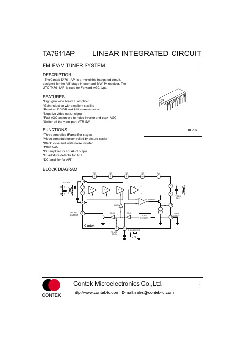
TA7611AP中文资料
820kW
0.01 mF
1000pF
0.01 mF16来自151413
12
11
10
9
3.9kW
75pF
Contek TA7611AP
1 2 3 4 5 6 7 8
1kW 5kW 1kW
1.6kW
SW2
1
2
Contek Microelectronics Co.,Ltd.
CONTEK
E-mail:sales@
TEST CIRCUIT 1
5.1k W
LINEAR INTEGRATED CIRCUIT
3.3k W 1 2 3.9k W Vcc=12V
820kW
1.6k W 0.01 mF
0.01 m F
SW4
A
47 mF
0.01 mF
16
0.01 mF
15
14
13
12
11
10
9
Contek
1 2 3
TA7611AP
FUNCTIONS
DIP-16
*Three controlled IF amplifier stages *Video demodulator controlled by picture carrier *Black noise and white noise inverter *Peak AGC *DC amplifier for RF AGC output *Quadrature detector for AFT *DC amplifier for AFT
BLOCK DIAGRAM
NC NC NC NC Vcc
5
IF INPUT
6
LA76810A引脚功能

LA76810A引脚功能1.AUDIO OUT伴音音频输出2.4伏2.FM OUT伴音检波输出2.4伏3.PIF AGC中频AGC 2.6伏4.RF AGC高频AGC 1.7伏5.VIF IN1图像中频输入12.8伏6.VIF IN2图像中频输入22.8伏7.GND(IF)中放地0伏8.VCC(VIF)中放电源5伏9.FM FIL伴音检波滤波2.3伏10.AFT OUT AFT输出2.7伏11.DATA数据总线4.7伏12.CLOCK时钟总线4.7伏13.ABL自动亮度控制3.9伏14.R IN红字符输入0.9伏15.G IN绿字符输入0.9伏16.B IN蓝字符输入0.9伏17.BLANK IN字符消隐输入0伏18.VCC(RGB) RGB电源7.9伏19.R OUT红输出1.8伏20.G OUT绿输出1.8伏21.B OUT蓝输出1.8伏22.SYNC同步信号输出0.4伏23.V OUT场推动信号输出2.2伏24.RAM PALC FIL场锯齿波形成滤波2.8伏25.VCC(H)行电源5伏26.H AFC FIL行AFC滤波2.6伏27.H OUT行推动信号输出0.7伏28.FBP IN行逆程脉冲输入,沙堡脉冲形成1.1伏29.VCO IREF行参考电流1.6伏30.CLOCK OUT 4MHZ时钟信号输出0.9伏31.VCC(CCD)1H-CCD电源4.5伏D FIL 1H-CCD滤波8.3伏33.GND(CCD/H) 1H-CCD/行振荡地0伏34.SECAM B-Y IN SECAM B-Y输入2.4伏35.SECAM R-Y IN SECAM R-Y输入2.4伏36.APC2 FIL APC2滤波3.7伏37.FSC OUT负载波输出2.2伏38.XTAL4.43MHZ晶体振荡2.7伏39.APC1 FIL APC1滤波3.4伏40.SELEC V OUT视频选择输出2.1伏41.GND(V/C/D)视频/色度/偏转电路地0伏42.EXT VIDEO IN外视频信号/Y信号输入2.4伏43.VCC(V/C/D)视频/色度/偏转电路电源5伏44.INT VIDEO IN内视频信号/C信号输入2.7伏45.BLACK STR FIL黑电平延伸滤波3.1伏46.VIDEO OUT视频信号输出1.8伏47.VCO FIL中频PLL环路滤波3.4伏48.VCO COIL图像解调振荡线圈外接端3.2伏49.VCO COIL图像解调振荡线圈外接端4.2伏50.PIF FIL图像中频APC外接滤波端2.3伏51.EXT AUDIO IN机外音频信号输入端2.2伏52.SIF OUT第二伴音中频信号输入端2.1伏53.SIF APC FIL伴音解调APC外接滤波端2.2伏54.SIF IN第二伴音中频信号输入端3.1伏。
Additel 761A自动高压测量仪说明书

Series Automated Pressure CalibratorsAdditel 761AAutomated and self-contained pressure generation and control to 1,000 psi ( 70 bar)Standard accuracy to 0.02%FSOptional precision accuracy models to 0.01%FSTwo removable internal pressure modules for multi-range selection Control stability to 0.003%FSPortable, designed for use in the field and in the lab Ability to measure two external pressure modules Wi-Fi, Bluetooth, USB and Ethernet communication HART and profibus communication Data logging and task managementPatented electric pump technology and improved speed OVERVIEWAt Additel, innovation and continuous improvement are part of our company's culture and the products we introduce. When we set out to deliver the Additel 761A series calibrators, we knew we needed to provide breakthrough improvements and additional value to the existing line of calibrators (Additel 761 series). The ADT761A has many improvements: increased pressure range to 1,000 psi (70 bar), removable internal pressure modules, optional precision models to 0.01%FS, increased speed to pressure, ability to read two external pressure modules, touch screen display, Wi-Fi, Bluetooth, and Ethernet communications, double the original battery life, and more!Just like the first generation, this second generation product is completely self-contained and automated with a built-in pump for pressure generation and precision control technology. Simply set the desired pressure and watch the calibrator do thework.ADT761A-LLPThe Additel 761A-LLP is designed for low pressure calibration and comes with a ±30 inH2O (±75 mbar) high range module and a low range module of your choice ranging from ±20 inH2O to as low as ±0.25 inH2O (±50 to ±0.62 mbar). This unit has an accuracy of 0.05%FS with control stability better than 0.005%FS. All measurements can be made in differential or gaugepressures.ADT761A-DThe Additel 761A-D also provides differential and gauge measurement which covers the range of -13.5 to 35 psi (-0.95 to 2.5 bar). This unit comes with a CP35 module (-13.5 to 35 psi) and one low range module of your choice rangeing as low as ±10 inH2O (25 mbar). Each ADT761A-D can be preconfigured with the modules that fit your need to give you the best precision at the pressures you perform calibrations.ADT761A-500The Additel 761A-500 will generate and control from vacuum pressures upto 500 psig (35 bar.g). Both gauge and absolute pressures can be realizeddue to a built-in barometer. Each unit comes with a CP500 module (-13 to500 psig) for the high range and the low range can be preconfigured basedon the variety of modules available down to 10 psig (0.7 bar.g).ADT761A-1KThe Additel 761A-1K will generate and control from vacuum pressures up to 1,000 psig (70 bar.g). This unit can typically achieve 1,000 psi in less than 45 seconds. Like the ADT761A-500, both gauge and absolute pressures can be realized due to a built-in barometer. Each unit comes with a CP1K module (-13 to 1,000 psig) for the high range and the low range can be preconfigured based on the variety of modules available down to 30 psig (2 bar.g).ADT761A-APXR Precision Accuracy OptionsThe Additel 761A series includes a precision accuracy option whichprovides an accuracy of 0.01%FS. This calibrator option includes a singlenon-removable sensor and can measure absolute and gauge pressures.Model configurations are available from 15 to 1,000 psig (1 to 7 bar.g).ADT761A-BPThe Additel 761A-BP is designed for calibration of barometer sensors. Witha range of 100 to 1200 hPa and an accuracy of 0.01%FS, this unit is idealfor calibration on the bench or in the field.Pressure SpecificationsElectrical Specifications[1] One year accuracy (including 1 year stability). FS specification applies to the span of the module range.[2] Specification based on gauge measurement. An additional 60 pa uncertainty will need to be included when measuring in absolute mode. Applicable only for use with the ADT761A-500 and ADT761A-1K* Additel 761A calibrators support 160A series intelligent digital pressure modules that are available for gauge, vacuum and absolute pressure from -15 psi to 60,000 psi (-1 bar to 4200 bar). For detailed specifications refer to the 160A series pressure modules data sheet.Internal Module Specification and Compatibility[1] FS specification applies to the span of the module range. Accuracy includes one-year stability, except for DP025 to DP10 modules.[2] Accuracy is a 6 months spec, 1-year long-term drift is 0.2%FS.[3] Accuracy is a 6 months spec, 1-year long-term drift is 0.1%FS.[4] Accuracy is a 6 months spec, 1-year long-term drift is 0.05%FS.[5] Specification based on gauge measurement. An additional 60 pa uncertainty will need to be included when measuring in absolute mode.Applicable only for use with the ADT761A-500 and ADT761A-1KPressure gauge / transmitter / switch calibrationGeneral SpecificationsPressure RangeHigh-Range Pressure ModuleLow-Range Pressure Module Accuracy RangeAccuracyDP30: -75 to 75 mbar 0.05%FSUser selectable fromDP20 to DP025See Internal ModuleTable CP35: -0.95 to 2.5 bar 0.02%FSUser selectable from DP10 to CP30See Internal ModuleTable Task ManualHigh Pressure Automated CalibrationORDERING INFORMATIONModel NumberNPressure Range。
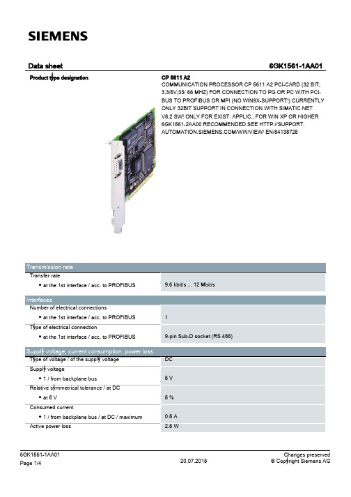
西门子CP5611A2通信处理器PCI卡数据手册说明书
PCI 18 mm 102 mm 130 mm 100 g 1
-
Performance data
Performance data / open communication Software / for open communication / by means of SEND/RECEIVE / required Number of possible connections / for open communication / by means of SEND/RECEIVE / maximum
6GK1561-1AA01 Page 3/4
20.07.2015
Changes preserved © Copyright Siemens AG
Security information Security information
last modified:
Siemens provides products and solutions with industrial security functions that support the secure operation of plants, solutions, machines, equipment and/or networks. They are important components in a holistic industrial security concept. With this in mind, Siemens’ products and solutions undergo continuous development. Siemens recommends strongly that you regularly check for product updates. For the secure operation of Siemens products and solutions, it is necessary to take suitable preventive action (e.g. cell protection concept) and integrate each component into a holistic, state-of-the-art industrial security concept. Thirdparty products that may be in use should also be considered. For more information about industrial security, visit /industrialsecurity. To stay informed about product updates as they occur, sign up for a product-specific newsletter. For more information, visit http://support.automation.sห้องสมุดไป่ตู้. (V3.4)
7613AP双极型线性集成电路

7613AP
双极型线性集成电路
1.2k
FM
SW1
AM
Rg=50
~ 高频
信号
Rg=600
~ 音频
信号
470 F 220pF 220 F
V16
V13
0.047 F
1
6
2
3
4
4
3
2
470 F
4
3
2
6
1
4.7k
6
1
10pF
16 15 14 13 12 11 10
470 F
0.001 F
9
UTC7613AP
DIP-16
内部框图
调幅中 频输出
调幅 / 调频 中频 高频地 输入 旁路
调幅 / AGC 调频 旁路 输出
中频 / 检测
输入
4
3 2 1 16 15 14
调幅高 频混频
调幅 / 调 频中频
调幅 / 调 频鉴频
+Vcc 13
调整
调幅 L.O
56
7
调幅 调幅 高频 本振 高频 旁路
输入
音频 放大
8 9 10 音频 音频 纹波 检测 功率 抑制 输出 输入
参数
符号
测试条件
最小值 典型值 最大值 单 位
静态电流
16脚电压 限幅电压
内部稳压 16脚电压 最大灵敏度
信噪比
输出功率
总谐波失真
电压增益
ICCQ
V16(FM) VIN(lim)
VCC V16(AM)
VO
S/N
POUT
THD
GV
SW1 FM,VCC=3V SW1 FM,VCC=9V SW1 FM,ICC=42mA,无信号 SW1 FM,VCC=5.5V,-3dB V16=2.4V,VR=Min. SW1 AM,ICC=42mA SW1 AM,VCC=9V,无信号 SW1 AM,VCC=12V,VIN=37dB SW2 45 ,V16=1.4V SW1 AM,VCC=5.5V, SW2 8 ,VIN=37.5dB SW2 8 ,VCC=5.5V,f=1KHZ VR=Min. THD=10% SW2 45 ,ICC=42mA,f=1KHZ VR=Min. VOUT=2V SW2 8 ,VCC=5.5V,f=1KHZ
ICL7611DCBAZ中文资料

Operating Conditions
Temperature Range ICL761XC. . . . . . . . . . . . . . . . . . . . . . . . . . . . . . . . . 0°C to +70°C
Thermal Information
Thermal Resistance (Typical, Note 3)
170
Maximum Junction Temperature (Plastic Package) . . . . . . . +150°C
Maximum Storage Temperature Range . . . . . . . . . -65°C to +150°C
Maximum Lead Temperature (Soldering 10s) . . . . . . . . . . . +300°C
2FN2919.8September 27, 2006
元器件交易网
ICL7611, ICL7612
Absolute Maximum Ratings
Supply Voltage V+ to V- . . . . . . . . . . . . . . . . . . . . . . . . . . . . . . . 18V Input Voltage . . . . . . . . . . . . . . . . . . . . . . . . . . . V- -0.3 to V+ +0.3V Differential Input Voltage (Note 1) . . . . . . . . [(V+ +0.3) - (V- -0.3)]V Duration of Output Short Circuit (Note 2). . . . . . . . . . . . . . Unlimited
Moog G761 761系列工业伺服阀安装、操作和故障排除手册说明书

ELECTROHYDRAULIC VALVE CUT -AWA YFigure 1 Moog Series G761/761Upper Polepiece Flexure Tube Lower Polepiece FlapperInlet OrificeCoil Armature NozzleFeedback WireSpoolP A T B P xFilter3. HYDRAULIC SYSTEM PREPARATIONT o prolong servovalve operational life and to reduce hydraulic system maintenance, it is recommended that the hydraulic fluid be kept at a cleanliness level of ISO DIS 4406 Code 16/13 maximum, 14/11 recommended. The most effective filtration scheme incorporates the use of a kidney loop or “off-line” filtration as one of the major filtration components. The filter for the “off-line” filtration scheme should be a B 3≥75 filter for maximum effectiveness.U pon system startup and prior to mounting the servovalve, the entire hydraulic system should be purged of built-in contaminating particles by an adequate flushing. The servovalve should be replaced by a flushing manifold and the hydraulic circuit powered up under conditions of fluid temperature and fluid velocity, reasonably simulating normal operating conditions. New system filters are installed during the flushing process whenever the pressure drop across the filter element becomes excessive. The flushing processes should turn over the fluid in the reservoir between fifty to one hundred times.T o maintain a clean hydraulic system, the filters must be replaced on a periodic basis. It is best to monitor the pressure drop across the filter assembly and replace the filter element when the pressure drop becomes excessive. In addition to other filters that are installed in the hydraulic circuit, it is recommended that a large capacity, low pressure ß3≥75 filter be installed in the return line. This filter will increase the interval between filter element replacement and greatly reduce the system contamination level.4. PILOT STAGE OIL SUPPL Y AND NAMEPLATEMODIFICATION (applies to models G761-3001B through G761-3010B)T he Moog G761/761 series industrial servovalve can be configured for pilot stage oil supply through the internal pressure “P” port, or from a separate supply line through the “X” port. Standard configuration is internal pilot operation with a screw and seal washer in the “X” port. This same screw and seal washer must be relocated to the “P” port if an external pilot oil supply source is desired. Refer to Figure 2 for screw and seal washer locations.U pon valve installation, the nameplate must display the proper hydraulic schematic and typecode (if applicable). The nameplate currently shows internal (4th port) pilot hydraulic schematics and typecode. If a separate pilot supply will be used, please attach the provided lower half label showing external (5th port) information. See Figure 3.5. INSTALLATIONT he Moog G761/761 series industrial servovalve may be mounted in any position, provided the servovalve pressure, control and return ports match their respective manifold ports.T he mounting pattern and port locations of the servovalve are shown on Figure 6. The servovalve should be mounted with 5/16-18 x 1.75 inch long, socket head cap screws. Apply a light film of oil to the screw threads and torque to 96 inch pounds. Wire the mating connector for desired coil configuration and polarity. Thread the connector to valve.6. NULL ADJUSTMENTI t is often desirable to adjust the flow null of a servovalve independent of other system parameters. The “mechanical null adjustment” on the Moog G761/761 series servovalve allows at least ±20% adjustment of flow null.T he “mechanical null adjustor” is an eccentric bushing retainer pin located above the “return” port designation on the valve body (see Figure 4) which, when rotated, provides control of the bushing position. Mechanical feedback elements position the spool relative to the valve body for a given input signal. Therefore, a movement of the bushing relative to the body, changes the flow null.Mechanical Adjustment ProcedureUsing a 3/8 inch offset box wrench, loosen the self-locking fitting until the null adjustor pin can be rotated. (This should usually be less than 1/2 turn). DO NOT remove self-locking fitting. Insert a 3/32 inch Allen wrench in null adjustor pin. Use the 3/32 Allen wrench to rotate the mechanical null adjustor pin to obtain desired flow null. T orque self-locking fitting to 57 inch lbs.Figure 3Sample Nameplate7. GENERAL SERVICING RECOMMENDATIONSa. Disconnect the electrical lead to the servovalve.b. Relieve the hydraulic system of residual pressure.c.Remove the servovalve.Figure 4Mechanical Null AdjustmentImportant:Local regulations may require precise hydraulic labeling on components!Potential TroubleServovalve does not follow input command signal. (Actuator or components are stationary or creeping slowly).High threshold. (Jerky, possible oscillatory or “hunting” motion in closed loop system).Poor response. (Servovalve output lags electrical command signal).High Null Bias, (High input currentrequired to maintain hydraulic cylinder or motor stationary).Probable Cause1. Plugged filter element.1. Plugged filter element.1. Partially plugged filter element.1. Incorrect null adjustment.2. Partially plugged filter element.Remedy1. Replace filter element.1. Replace filter element.1. Replace filter element.Check for dirty hydraulic fluid in system.1. Readjust null.2. Replace filter element and check for dirty hydraulic fluid in system.8. TROUBLESHOOTING CHARTThe following troubleshooting chart lists potential troubles encountered, probable causes and remedies.9. FILTER ASSEMBL Y REPLACEMENTT ools and Equipmenta. 3mm Allen wrenchb. T orque wrencha. Remove the four socket head cap screws with 3mm Allen wrench.b. Remove the filter retainer.c. Remove and discard the filter disc.d. Remove and replace the o-ring on the filter retainer and the o-ring in the filter bore.e.Reinstall in reverse order, torque screws to 35-40 in-lbs.10. FUNCTIONAL CHECK OUT AND CENTERINGa. Install servovalve on hydraulic system or test fixture, but do not connect electrical lead.b. Apply required system pressure to servovalve and visually examine for evi- dence of external leakage. If leakage is present and cannot be rectified by replacing o-rings, remove the discrepant component and return for repair or replacement.Note: If the system components are drifting or hardover, adjust the mechanical null of the servovalve.c. Connect electrical lead to servovalve and check phasing in accordancewith system requirements.11. AUTHORIZED REPAIR FACILITIESMoog does not authorize any facilities other than Moog or Moog subsidiaries to repair its servovalves. It is recommended you contact Moog at (716) 652-2000 to locate your nearest Moog repair facility. Repair by an independent (unauthorized) repair house will result in voiding the Moog warranty and could lead to performance degradation or safety problems.Figure 5Socket Head Cap Screw2X O-RingP/N -42082-003Filter RetainerFilterP/N A67999-0652X O-Ring P/N G2141-013-015G761/761 SERIES INSTALLATION AND OPERATION INSTRUCTION NOTES2Figure 6Moog Inc., Industrial Group/industrialUnitedStates:phone+****************************Europe:phone+*******************************AsiaPacific:phone+******************************For a complete list /industrial/globallocatorThe products described herein are subject to change at any time without notice, including, but not limited to, product features, specifications, and designs.CDS6673 Rev E 1216。
DX761Z-UST DW763Z-UST系列 使用说明书

ϡ͗͘ΊրЕFCC 声明此设备经测试证实,符合 FCC 规则第 15 部分关于 B 级数字设备的限制要求。
这些限制的目的是为了在居住区安装时提供合理保护以防止有害干扰。
如果不按照指示进行安装和使用,可能会对无线通信产生有害干扰。
但本公司不保证在特定安装情况下不产生干扰。
如果此设备确实对无线电或电视接收造成有害干扰 (通过关闭后再打开存在疑问的设备来确定),建议用户尝试采取以下一项或多项措施来排除此干扰:• 调整接收天线的方向或位置• 增大设备和接收器之间的间距• 将设备和接收器分别连接到不同的电路插座上• 咨询经销商或经验丰富的专业无线电/电视技术人员以获取帮助。
此设备符合 FCC 规则第 15 部分的要求。
其运行符合下面两个条件:1.此设备不得导致有害干扰。
2.此设备必须承受任何干扰,包括可能导致意外操作的干扰。
安全说明在使用投影机前,请阅读所有这些指导说明,并妥善保管以备日后参考。
1.阅读指导说明在使用设备前,应阅读所有安全和使用指导说明。
2.注意和警告应遵循使用指导说明中的所有注意和警告。
3.清洁在清洁之前,从墙壁电源插座上拔掉投影机电源线插头。
使用湿布擦拭投影机外壳。
请勿使用液体或烟雾清洁剂。
4.附件切勿将投影机置于不稳的推车、架子或桌子上。
产品可能掉落,导致其严重损坏。
将(投影机、附件和选配件)的塑料包装材料放在儿童够不到的地方,否则包装袋可能导致窒息死亡。
对于婴幼儿更要特别注意。
5.通风此投影机配有进气和排气通风孔。
请勿堵塞这些开口或者在开口附近放置任何物品,否则内部可能积聚热量,并导致画面质量下降或投影机损坏。
6.电源确认本机的工作电压与您当地电源的电压相同。
7.维修请勿尝试自行维修此投影机。
委托专业技术人员进行维修。
8.更换部件当需要更换部件时,务必使用制造商指定的更换部件。
未经授权的更换可能导致火灾、触电或其他危险。
9.水汽凝结将投影机从寒冷的地点移到温暖的地点后,切勿立即使用。
AD7616 16 通道 DAS 数据手册说明书

16通道DAS ,内置16位、双极性输入、双路同步采样ADC数据手册AD7616Rev. 0Document FeedbackInformation furnished by Analog Devices is believed to be accurate and reliable. However, no responsibility is assumed by Analog Devices for its use, nor for any infringements of patents or other rights of third parties that may result from its use. Specifications subject to change without notice. No license is granted by implication or otherwise under any patent or patent rights of Analog Devices. Trademarks andregistered trademarks are the property of their respective owners.One Technology Way, P .O. Box 9106, Norwood, MA 02062-9106, U.S.A.Tel: 781.329.4700 ©2016 Analog Devices, Inc. All rights reserved. Technical Support /cnADI 中文版数据手册是英文版数据手册的译文,敬请谅解翻译中可能存在的语言组织或翻译错误,ADI 不对翻译中存在的差异或由此产生的错误负责。
如需确认任何词语的准确性,请参考ADI 提供的最产品特性16通道、双路、同步采样输入 可独立选择的通道输入范围真双极性:±10 V 、±5 V 、±2.5 V5 V 单模拟电源,V DRIVE 电源电压:2.3 V 至3.6 V 完全集成的数据采集解决方案 模拟输入箝位保护具有1 MΩ模拟输入阻抗的输入缓冲器 一阶抗混叠模拟滤波器片内精密基准电压及基准电压缓冲器双通道16位逐次逼近型寄存器 (SAR)ADC 吞吐速率:2×1 MSPS通过数字滤波器提供过采样功能 灵活的序列器,支持突发模式 灵活的并行/串行接口SPI/QSPI/MICROWIRE/DSP 兼容 可选循环冗余校验 (CRC) 错误检查 硬件/软件配置 性能信噪比 (SNR):92 dB (500 kSPS 、2倍过采样) 信噪比 (SNR):90.5 dB (1 MSPS) 总谐波失真 (THD):−103 dB ±1 LSB INL (典型值),±0.99 LSB DNL (最大值) 模拟输入通道提供8 kV ESD 额定值 片内自检测功能 80引脚LQFP 封装应用电力线路监控 保护继电器 多相电机控制仪器仪表和控制系统 数据采集系统 (DAS)概述AD7616是一款16位DAS ,支持对16个通道进行双路同步采样。
ad7616用法 -回复

ad7616用法-回复Ad7616用法: 一步一步回答第一步:了解AD7616AD7616是一款由Analog Devices(简称ADI)公司生产的高性能、低功耗、多信道、16位模数转换器(ADC)芯片。
AD7616芯片具有16个单端或8个差分输入通道,适用于广泛的应用领域,如自动测试设备、数据采集系统、医疗仪器、仪器仪表等。
第二步:理解AD7616的特性AD7616具有许多出色的特性,使其成为许多应用的理想选择。
以下是AD7616的一些主要特性:1. 高精度:AD7616是一个16位ADC,具有超过96 dB的信噪比和小于±2 LSB的差分非线性误差。
这使得它在需要高精度测量的应用中非常有用。
2. 多信道:AD7616提供16个单端或8个差分输入通道,可以同时采集多个信号,使其适用于需要多通道数据采集的应用。
3. 低功耗:AD7616具有低功耗特性,仅需小于100 mW的电源功耗,同时具备快速的采样速率和转换率,使其在低功耗要求较高的应用中非常有用。
4. SPI接口:AD7616通过串行外设接口(SPI)进行控制和数据传输。
SPI通信协议简单、高效,减少了与芯片的连接复杂性,使其易于集成到现有系统中。
第三步:AD7616的使用步骤使用AD7616的基本步骤如下:1. 硬件连接:将AD7616芯片与要采集的信号源进行连接。
根据应用需求选择单端输入通道还是差分输入通道,并正确接线。
2. 电源供应:为AD7616提供适当的电源电压和电流。
请参考AD7616数据手册,以确保为芯片提供正确的电源。
3. SPI配置:通过SPI接口,将要配置AD7616的设置发送到芯片中。
可以使用微控制器或其他SPI Master设备来完成此操作。
4. 数据采集:一旦AD7616开始工作,它将开始将输入信号转换为数字输出。
使用SPI接口读取转换后的数据,并根据需求进行处理或存储。
第四步:AD7616的示例应用AD7616广泛用于许多应用场景中。
DAC7611中文资料(附有C程序)

DAC7611 中文资料1、电路图:引脚符号描述1 VDD 电源2 ~CS 芯片选择信号输入引脚,低电平有效3 CLK 同步串行时钟输入4 SDI 串行数据输入,在串行时钟的上升沿数据被移入DAC7611内部的串行移位寄存器.5 ~LD 装载控制信号。
控制移入的数据装载到DAC7611内部的DAC寄存器,触发数模转换。
低电平有效。
它的工作与串行时钟(CLK)和芯片选择信号(~CS)无关。
6 ~CLR 异步DAC寄存器清零输入。
它的工作与(CLK)和芯片选择信号(~CS)无关。
低电平有效。
当CLR为低电平时DAC 寄存器被置零000H,使DAC7611 输出电压为0V7 GND 接地8 Vout 电压输出。
电压范围在0到4.095v(1mV/LSB)2、时序图程序范例:<DAC7611.C>#include<msp430x14x.h>/******************************************************宏定义*******************************************************/ #define SDI BIT0#define CLK BIT1#define CS BIT2#define LD BIT3#define U0 BIT4#define SDI_1 P2OUT |=SDI#define SDI_0 P2OUT &=~SDI#define CLK_1 P2OUT |=CLK#define CLK_0 P2OUT &=~CLK#define CS_1 P2OUT |=CS#define CS_0 P2OUT &=~CS#define LD_1 P2OUT |=LD#define LD_0 P2OUT &=~LD/******************************************************控制量*******************************************************/ unsigned int DaDate=0x800; // 待转换的数据/******************************************************端口初始化*******************************************************/ void init(){P2DIR |=0x0f; //P1低四位输出P2DIR &=~0x10; //P1.4输入}/*******************************************************延时函数********************************************************/ void delay(unsigned int time){while(time--);}/*******************************************************DAC7611初始化********************************************************/ void da_init(){LD_0;CS_1;CLK_1;SDI_0;delay(10);}/******************************************************DA转换程序*******************************************************/void DAConv(unsigned int DaDat){unsigned char i=0;LD_1;CS_0;CLK_0; //在第一时钟周期的上升沿开始把数据移入DAC7611delay(100);for(i=0;i<12;i++){if(DaDat & 0x800)//判断移入一位数是1 还是0SDI_1;elseSDI_0;CLK_0;delay(10);CLK_1;DaDat =DaDat<<1;}CLK_1;delay(5);CS_1; //CS 保持高电平delay(10);LD_0; //装载引脚为低电平时,数字/ 模拟转换过程启动LD delay(10);LD_1;}<MAIN.C>#include"DAC7611.c"/******************************************************主函数*******************************************************/ void main(){init();da_init();while(1){DAConv(DaDate);delay(10);}}。
761的使用方法
761的使用方法
761的使用方法
一、安装
1、将761放入电脑PCI插槽中,并将主板电源插头连接到761上。
2、将765的驱动光盘放入光驱中,弹出安装界面,选择“开始安装”,自动安装761的驱动程序。
3、安装完成后,检查761是否连接正确,检查安装的驱动程序是否正确,若正确,则安装完成。
二、使用
1、打开电脑,等待操作系统载入完毕,系统就会识别761,并自动安装驱动程序;
2、检查761的工作情况,确保它正常工作;点击“我的电脑”可以查看761的运行情况;
3、在“我的电脑”界面中,点击“设备管理器”,即可看到761的软件;
4、点击设备管理器中761的软件,则可以进行各种设置和配置761,如系统设置、声卡设置、输入/输出设置等。
五、维护
1、定期清洁761,可以用吸尘器除尘;
2、确保761的供电是正常工作的;
3、检查电脑与761连接线是否牢固;
4、确保761的软件和驱动程序是最新的,可定期更新;
5、如果761出现异常,及时重新安装761的驱动程序,以保证正常工作。
ad7616用法

AD7616 是一款16 通道、12 位数模转换器(ADC),它采用了串行接口(SPI)控制。
以下是AD7616 的用法概述:
1. 确定电路连接
AD7616 的引脚功能和连接方式详见其数据手册,需要根据应用场景来确定电路连接方式,包括控制接口、电源和参考电压等。
2. 初始化SPI 接口
使用硬件引脚或者软件库初始化SPI 接口,以确保AD7616 能够与主机正常通讯。
3. 编写控制程序
在主控芯片上编写控制程序,配置AD7616 的寄存器,决定数据的采样方式,如数据输出速率、同步方式、输入范围等。
以下是一些AD7616 可配置的寄存器及其作用:
- CONFA 寄存器:控制通道A/B 的输入范围和增益;
- CONFCHx 寄存器:控制单个通道输入范围和是否单端/差分输入;
- MODE 寄存器:控制采样率和同步方式;
- OFFSETx 寄存器:用于补偿通道的偏移量,以增强数据的精度和稳定性。
4. 读取数据
AD7616 的数据输出是通过SPI 接口返回的,主机芯片通过SPI 帧读取AD7616 的转换结果,并将其转换为与信号相关的实际值,如电压、电流等。
