星辰伺服驱动说明书
星辰伺服
星辰伺服—在节能型注塑机中的优点一、节能采用星辰伺服的注塑机,系统压力、流量双闭环,液压系统按照实际需要的流量和压力来供油,克服了普通定量泵系统高压溢流产生的高能耗,在预塑、合模、射胶等高流量工作阶段电机按照设定的转速工作,在保压、冷却等低流量工作阶段降低了电机转速,油泵电机实际能耗降低了50%--80%;二、响应迅速,生产效率高星辰伺服响应速度快,压力上升时间和流量上升时间快至30ms,提高了液压系统的响应速度,减少了动作转换时间,加快了整机的运行节拍;注塑机液压系统自动运行时,当有阀门打开时,系统压力会瞬间下降,星辰伺服可以在30ms以内迅速补充油量,恢复压力至设定值;三、压力、稳定精密星辰伺服调节能力强,压力闭环控制模式使系统压力非常稳定,压力波动量低于±0.5kg,提高了塑料产品的成型质量;星辰伺服还可以按照电脑设定的任意压力、流量曲线运行,为开发各种塑料产品的成型工艺创造了条件;四、重复精度高、省料星辰伺服采用闭环转速控制,射台运动位置重复精度高,生产出的产品精度高,一致性好;克服了普通异步电机定量泵系统由于电网电压、频率等变化会带来转速变化,进而引起流量变化,使注塑产品成品率降低的缺点;五、转速提升流量大采用恒功率控制技术,星辰伺服驱动器将额定转速1500RPM的电机恒功率升速到2000RPM,提高了注塑机射胶流速、开合模速度;在保证同等流量时可以选择小一号排量的泵,以及小一级功率的电机和驱动器,进而降低系统成本;六、适配多种油泵星辰伺服电机与油泵通过无间隙联轴节连接,电机的热量不会直接传导到油泵上,减低油温,方便油泵维护更换;星辰伺服可以配套螺杆泵、内啮合齿轮泵、柱塞泵、变量柱塞泵,方便用户生产不同产品时进行选型;例如注射PC等需要长时间保压的材料时,可以选择变量柱塞泵;七、使用方便星辰伺服驱动器提供压力、流量双闭环控制,与双路模拟量输出的电脑进行联机,方便调试,普通技术人员通过数字面板即可迅速调好参数,也可用数字接口批量写入适配参数;星辰伺服系统集成度高,降低了电气装配、采购难度;八、技术领先、专业制造星辰多年来为国产军用系统提供产品,养成了对质量、技术精益求精的良好作风;星辰伺服电机和驱动器全部由星辰公司自己设计、制造,动力伺服是我们的特点;九、供货、服务迅速星辰是民营高科技公司,注重产品和服务的竞争力,在珠江三角洲和长江三角洲都设有自营销售服务机构,保证高水平技术服务,保证及时供货,全心全意为国产整机制造业服务;更适合如下产品:1,深腔薄壁制品2,亚客力透明制品,表面无流纹3,厚壁,保压时间长的制品,表面无凹陷,节能效果更明显4,重复精度要求高的结构件选型参考:。
伺服驱动器用户手册
2.2.2、通风间隔
2.2.3、安装方法 1)、安装方向:伺服驱动器的正常安装方向是垂直直立方向。 2)、安装固定:上紧伺服驱动器上的四颗 M5 固定螺钉。 3)、通风散热:采用自然冷却方式,在电气控制柜内必须安装散热风机。
z 拆装带轮时,不可敲击电机或电机轴,防止损坏编码器。应采用螺旋式压 拔工具拆装
z 驱动器端子 U、V、W 必须与电机 U、V、W 一一对应 z 用户在使用本产品时务必在设计与装配时考虑安全防护措施,以防止
因错误的操作引起意外事故 z 驱动器和电机必须良好接地 z 在拆卸本驱动器前,必须断电 5 分钟以上
3.1、标准接线
本交流伺服驱动器的接线与使用的电机和控制方式等有关。
10
3.1.1、与武汉华大、常州常华、常州新月 4 对极电机控制接线图 3-1,对南 京苏强 110SQMA4IE 系列 4 对极电机只需将 UVW 接电机的 423 脚 对应参数 P34=2360、P35=4
20A
30A
50A
75A
100A 150A
≤1.2KW
25A ≤3.7KW
≤2.3KW ≤3.7KW ≤5.5KW ≤7.5KW
AC380V -15%~+10%
50A
75A
≤7.5KW ≤11KW
≤11KW
工作:45℃
存贮:-40℃~55℃
40%~80%无结露 86-106kpa ①位置控制 ②JOG 控制 ③速度控制 ④转矩控制 ⑤位置和速度控制 ⑥内部脉冲控制 ⑦电动刀架控制 ⑧位置和转矩控制 ①脉冲+方向 ②CW+CCW 脉冲 ③两相 AB 正交脉冲 0.01% ≤200Hz ≥500kHz 1:5000 内置 1/30000~30000/1 ≥300% 2500p/r 电机转速、电机电流、电机转矩、电机位置、位置偏差、指 令脉冲数、脉冲频率、直线速度、输入输出诊断 超速、过流、过压、欠压、过载、超差、编码器故障、温度 过高、内部芯片故障、模块故障
伺服驱动器 用户手册v1.0版本(1)

直通保护、电流检测异常、继电器吸合异常等保护功能。 完善的端子保护功能:控制端子+24V、+10V 电源的短路和过载保护,操作面板电缆反插保护,输入信
转矩ቤተ መጻሕፍቲ ባይዱ
电流
速度
母线电压
图 1 0Hz→正转 50Hz→0Hz→反转 50Hz→0Hz 的急加减速四象限运行
真正实现无跳闸运行
优异的电流和电压控制技术,以 0.1s 指令反复交替加速和减速,驱动器稳定无跳闸运行。 超强的负载能力,在任意加减速时间和任意冲击负载条件下,驱动器稳定无跳闸运行。 短时过载能力强,200%的额定负载条件下可连续工作 0.5s,150%的额定负载条件下可连续工作 1 分钟。 智能的模块温度控制,最大限度发挥驱动器带负载能力。
主辅给定运算结果的正负可自动确定电机旋转的方向。
上位机通讯
操作面板和端子均提供 485 接口,通讯协议为 Modbus,提供上位机监控软件。 可实现多台驱动器之间的主从通讯控制。 可实现参数上传和下载功能。 可实现数字分频器功能的多台驱动器运行频率的级联传递。
客户化功能
多种功能码显示方式
安装
注意 搬运、安装时,请托住产品底部,不能只拿住外壳,以防砸伤脚或摔坏驱动器。 驱动器要安装于金属等阻燃物上,远离易燃物体,远离热源。 安装作业时切勿将钻孔残余物落入驱动器内部,否则可能引起驱动器故障。
接线
危险 必须由合格的电气工程人员进行接线工作,否则有触电或损坏驱动器的危险。 接线前需确认电源处于断开状态,否则可能有触电或火灾的危险。 接地端子 PE 要可靠接地,否则驱动器外壳有带电的危险。 请勿触摸主回路端子,驱动器主回路端子接线不要与外壳接触,否则有触电的危险。 制动电阻器的连接端子是 B1、B2。请勿连接除此以外的端子,否则可能引起火灾。 驱动器整机的漏电流大于 3.5mA,漏电流的具体数值由使用条件决定,为保证安全,驱动
BBF-D(HD)A系列双轴交流伺服驱动器使用说明书2011.10.20

2. 安装及选型...........................................................................................................................6
2.1 BBF-HDA 系列伺服驱动器外形尺寸............................................................................................. 6 2.2 环境要求.......................................................................................................................................... 6 2.3 伺服单元的安装.............................................................................................................................. 7
伺服驱动器中文说明书
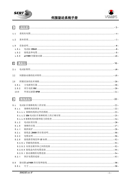
1.系统描述...................................................................................................................................- 3 -1.1系统布局图.......................................................................................................................................................- 4 -1.2基本原理...........................................................................................................................................................- 5 -1.3设备说明...........................................................................................................................................................- 6 -1.3.1电动缸DEMxB...........................................................................................................................................- 6 -1.3.2接线盒和电缆..........................................................................................................................................- 8 -1.3.3ACV9BR伺服驱动器...............................................................................................................................- 10 -2.技术规格....................................................................................................................................- 16 -2.1电动缸特性.....................................................................................................................................................- 16 -2.2伺服驱动器的技术特性.................................................................................................................................- 18 -2.3附属设备的技术规格.....................................................................................................................................- 20 -2.3.1主电源变压器........................................................................................................................................- 20 -2.3.2再生电阻RRC.........................................................................................................................................- 20 -2.3.3外部过滤器EFBR...................................................................................................................................- 21 -3.安装和接线.............................................................................................................................- 22 -3.1电动缸在塞棒机构上的安装.........................................................................................................................- 22 -3.1.1塞棒机构的准备....................................................................................................................................- 22 -3.1.1.1 塞棒机构固定件的图纸.....................................................................................................................- 22 -3.1.1.2 DEM电动缸在塞棒机构上的正确安装..............................................................................................- 23 -3.1.1.3塞棒机构间隙和阻力的检查..............................................................................................................- 24 -3.1.2电动缸的安装........................................................................................................................................- 26 -3.1.3塞棒的安装............................................................................................................................................- 27 -3.1.4隔热保护................................................................................................................................................- 28 -3.2.1接线盒JB9BR的安装说明.....................................................................................................................- 30 -3.2.2电缆说明................................................................................................................................................- 30 -3.2.3接线推荐规范和CE标准.......................................................................................................................- 32 -3.2.3.1 屏蔽线的接地.....................................................................................................................................- 32 -3.2.3.2 内部金属导体之间的连接.................................................................................................................- 32 -3.2.3.3 接线盒内的电缆连接.........................................................................................................................- 33 -3.2.3.4 驱动器侧的电缆连接.........................................................................................................................- 34 -3.2.4热区电缆的连接....................................................................................................................................- 35 -3.3驱动器ACV9BR的安装和接线.......................................................................................................................- 36 -3.3.1尺寸........................................................................................................................................................- 36 -3.3.2安装、定位和冷却................................................................................................................................- 37 -3.3.3电源的连接............................................................................................................................................- 39 -4.操作........................................................................................................................................- 40 -4.1手动模式.........................................................................................................................................................- 40 -4.2远程工作模式.................................................................................................................................................- 41 -4.3自动模式.........................................................................................................................................................- 41 -4.4塞棒关闭和安全装置.....................................................................................................................................- 42 -4.4.1塞棒关闭................................................................................................................................................- 42 -4.4.2断开电机电源(可选项).....................................................................................................................- 42 -4.5运行故障的处理.............................................................................................................................................- 43 -5.维护........................................................................................................................................- 44 -5.1检查周期.........................................................................................................................................................- 44 -5.2电动缸的检查和维护.....................................................................................................................................- 45 -5.3推荐的备件.....................................................................................................................................................- 49 -5.4伺服驱动器的故障代码.................................................................................................................................- 53 -5.5故障的数字输出代码.....................................................................................................................................- 57 -5.6驱动器复位和状态显示.................................................................................................................................- 58 -5.7没有报警显示时的故障排除.........................................................................................................................- 59 -6.辅助设备.................................................................................................................................- 61 -6.1DEM系列电动缸的测试台..............................................................................................................................- 61 -6.2塞棒机构MQS..................................................................................................................................................- 61 -1.系统描述SERT的塞棒执行器系统用于控制塞棒和塞棒机构的位置,以控制流入结晶器的钢水的流量。
伺服软件使用说明_最简洁版

ECO2WIN使用说明-简洁版深圳市步科电气有限公司目录第一部分: 特别需要注意的事项 (3)第二部分: 建立一个简单的工程 (9)第三部分: 进行简单的控制 (16)1功能介绍 (16)2 驱动器关键参数的设置 (17)电机参数设置 (17)电流环参数 (19)速度环PID调节 (20)位置环PID调节 (21)3 保存参数: (22)4 绝对位置、相对位置控制 (25)5 速度模式 (27)6 原点模式 (29)7 脉冲方向控制模式(跟随模式) (30)第四部分: 故障诊断 (34)第一部分: 特别需要注意的事项1、EC2WIN的所有文件,包装安装文件、电机参数文件、工程文件等都需要您放在英文目录下,同时必须详细阅读该手册里所有粗体或者带颜色的字体,运行电机前请确保所有连接线均正确连接到驱动器上;2、PC与ED伺服之间的连线为2、3、5脚直连线;3、如果您使用的是ED400、ED430、ED600、ED630系列的伺服驱动器,请先更新软件再进入下一步。
更新软件方法如下:把附件里的“DEV”文件夹里的两个文件解压出来,然后复制到EC2WIN的安装目录D:\Program Files\JAT\ECO2WIN\Dev里的两个文件“ENU和DEU”两个文件夹,替换以前的这两个文件即可。
4、如果您使用的3相电机,那么在新建或者连接已经建好的工程之前先用ECO2LOAD软件更新电机参数,三相电机的参数文件请参考附件,这些参数包括位置环、速度环、电流环、电机参数设置等参数,这样可以节省您设置这些参数的时间,同时也避免不小心设置成一个错误的值。
更新方法如下:1、打开“开始”菜单里的ECO2LOAD软件:2、然后进入软件界面:Write data into device:写参数到伺服驱动器;Read date out-of device:从伺服里读参数到文件Administration:管理伺服驱动器,用于重启和存储参数Load parameter list:选择读、写参数的内容,用来选择所要读取和做写入的是驱动器的哪些参数,正常情况下不用动这个按钮。
珊星伺服驱动器说明书

珊星伺服驱动器说明书
在自动化设备中,经常用到伺服电机,特别是方位操控,大部分品牌的伺服电机都有方位操控功用,经过操控器发出脉冲来操控伺服电机运转,脉冲数对应转的角度,脉冲频率对应速度(与电子齿轮设定有关),当一个新的体系,参数不能工作时,首要设定方位增益,保证电机无噪音状况下,尽量设大些,转动惯量比也非常重要,可经过自学习设定的数来参考,然后设定速度增益和速度积分时间,保证在低速运转时连续,方位精度受控即可。
设定方位环调节器的份额增益。
设置值越大,增益越高,刚度越大,相同频率指令脉冲条件下,方位滞后量越小。
但数值太大或许会引起振动或超调。
参数数值由详细的伺服体系类型和负载状况确认。
设定方位环的前馈增益。
设定值越大时,表明在任何频率的指令脉冲下,方位滞后量越小方位环的前馈增益大,操控体系的高速呼应特性提高,但会使体系的方位不安稳,容易发生振动。
不需求很高的呼应特性时,本参数通常设为0表明规模:0~100%。
设定速度调节器的份额增益。
设置值越大,增益越高,刚度越大。
参数数值根据详细的伺服驱动体系类型和负载值状况确认。
一般状况下,负载惯量越大,设定值越大。
在体系不发生振动的条件下,尽量设定较大的值。
设定速度调节器的积分时间常数。
设置值越小,积分速度越快。
参数数值根据详细的伺服驱动体系类型和负载状况确认。
一般状况下,负载惯量越大,设定值越大。
在体系不发生振动的条件下,尽量设定
较小的值。
传动之星(STAR@DRIVE)SD-7L伺服系统使用手册
Ⅱ-2
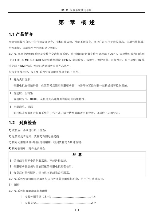
SD-7L 伺服系统使用手册
第三章 接线
警告
l 参与接线或检查的人员都必须具有做此工作的充分能力。 l 接线和检查必须在电源切断后 5 分钟以后进行,防止电击。
小心
l 必须按端子电压和极性接线,防止设备损坏或人员伤害。 l 驱动器和伺服电机必须良好接地。
3.1 标准接线
驱动器的外部连接与控制方式有关。 1) 位置控制方式
l 伺服驱动器须安装在电框内,防止尘埃、腐蚀性气体、导电物体、液体及易燃物侵入。
l 伺服电机和驱动器应避免振动,禁止承受冲击。
2.1 环境条件
项目
SD-7L 伺服驱动器
使用温/湿度
0~45℃(不结冻)
90%RH 以下(不结露)
储运温/湿度
-20~80℃
90%RH 以下(不结露)
大气环境
控制柜内无腐蚀性气体、易燃气体、油雾、尘埃等
Ⅰ-1
SD-7L 伺服系统使用手册 l CN1 插头(DB25 孔)…………………………………….1 套
(注 1)
l CN2 插头(DB25 针)…………………………………….1 套
(注 2)
【注 1】 配套我公司位置控制器时,与信号电缆(3 米)配套提供。
【注 2】 我公司提供伺服电机时,用户可选择反馈电缆(3 米)配套提供。
(1)防护
伺服驱动器自身结构无防护,因此必须安装在防护良好的电柜内,并防止接触腐蚀性、易燃性气体,防止导电物
体,金属粉尘、油雾及液体进入内部。
(2作温度在 45℃以下,并保证良好的散热条件。
(3)振动和冲击 驱动器安装应避免振动,采取减震措施控制振动有 0.5G(4.9m/s2)以下,驱动器的安装应不得承受重压和冲击。
星光xpress lodestar pro 光学导星系统用户手册说明书

Handbook for the SX ‘Lodestar PRO’ guideCameraThank you for purchasing a Starlight Xpress ‘Lodestar PRO’ guide camera. We hope that you will be very pleased with the performance of this product. Please register your product and warranty at https://forms.gle/tmsHEJfQG2bLJjr57 .The Lodestar PRO is an updated version of the very popular ‘Lodestar X2’. It is a very compact guider which is powered and operated via a single USB2.0 computer connection. It also provides an opto-isolated output connection for direct control of most mounts, via their ‘Autoguider’ sockets. This output is compatible with the ‘ST4’ style of RJ12 connection and supplies 4 ‘pull down’ direction lines and a common return. Alternatively, you may send the mount control signals via a serial connection from the guider control computer. The Lodestar PRO utilises a very sensitive Sony ‘ExView2’ CCD (the ICX829AL) with an array of 752 x 580 pixels in a ‘half-inch’ format sensor. Although the chip is not cooled, it has a very low dark signal and very little readout noise, so it can be used to guide on faint stars that are well beyond the reach of webcams and CMOS chip based guide cameras.The Lodestar PRO specification:CCD -Sony ICX829AL ExView2 monochrome CCDPixel count -752(H) x 580(V)Pixel size -8.6 x 8.3uMOptical size - 6.47 x 4.81 mmRead noise -Typically 5.5 electronsGain -0.75 e/ADUBarrel size -31.75mm dia. x 85mm long (1.25 inch eyepiece push fit size)Barrel thread -25.4mm x 0.75mm ‘CS’ mount lens threadInput connection - ‘Mini B’ USB socket for USB2.0Output connection - Standard RJ12 autoguider socketOutput type - Opto-isolated 4 lines (N,S,E & W) pull down with common return line Download rate -Approx. 10 frames per second in binned 2x2 mode (recommended)Installing the Lodestar PRO:Before connecting the Lodestar PRO to your computer, please install the appropriate drivers for your operating system from the USB drive supplied with your camera.The supplied USB stick contains all the drivers and software. To install the drivers:1.Select the folder for your operating system2.Double click on the “Install Drivers.exe”3.Follow the prompts in the installer and click ‘Finish’ at the end of the install.If you encounter any problems, read the README file on the USB drive or you can download the latest drivers from our web page at https:///drivers-downloads.The Lodestar PRO control software is Lodestar X2.exe. To install this:1.Double click on the Lodestar Software folder on the USB drive.2.Double click on the Setup.exe program3.Follow the prompts to fully install the software on to your computer.4.Plug in your Lodestar PRO camera – (Wait for the Install New Hardware Wizard to complete)5.Double click on the Lodestar X2.exe icon on your Desktop or from your START button on yourcomputer.6.The first time you use the software, click on “File” then “Set Program Defaults” You will get amessage, “Warning – No INI File found – Please set defaults”7.Click “OK” – The Set Program Defaults box will appear.8.If you are going to be using the RJ12 Autoguider Port on your Lodestar PRO, selectAutoguider Socket in the “Telescope Guiding Parameters” box at the top of this box.9.Click on “Save Changes” and you are all set to start using the camera. (The INI file that wasbeing asked for initially has now been created and you will no longer see the Warningmessage)PHD2 is also supplied on the USB stick. This is an excellent and very simple stand-alone Autoguiding Software. We would highly recommend trying this software as it is highly regarded in the Astro-Imaging community.Other 3rd party software packages such as AstroArt, MaximDL, SkyX and others, all support the Lodestar PRO either with native drivers or through ASCOM. Our latest driver can be found on our website: https:///support/resourcesUsing the Lodestar PRO:The Lodestar PRO is generally used with a separate guide telescope, or via an off-axis guider. It is designed to be inserted into a standard 1.25” focuser assembly, but also has a 25mm ‘C’ type camera lens thread in the front to allow standard CCTV lenses or adaptors to be attached. Please note that the chip to lens distance is only 12.5mm and so a ‘CS’ to ‘C’ extension will be needed to permit a standard C lens to reach focus. Lenses designed for ‘CS’ mount cameras will focus without an extension tube, but many of these lenses cannot fully illuminate a half-inch format CCD, so take care when selecting a lens for this purpose.A typical set up might consist of an inexpensive 80mm F5 refractor ‘piggybacked’ onto an SCT, with the Lodestar PRO fitted directly into its focus barrel. Many such telescopes are designed to be used with an inverting prism ahead of the eyepiece and so the focuser may be too short when the Lodestar PRO is inserted directly. In this case, an extension tube may often be made from a cheap Barlow lens assembly with the lens removed.The focal length of your guide telescope is not especially critical for good guiding, as the guiding software searches for the ‘centroid’ of the guide star image and can resolve shifts of far less than 1 pixel. Using a guide scope with a relatively short focal length (between 300 and 500mm) makes guide star finding very easy and this is a recommended setup for general purpose guiding.The control of your telescope mount will depend on what inputs are provided. The Lodestar PRO output connector supplies 4 pull-down lines and a common return line to simulate an ‘ST4’ style autoguider output. The lines are isolated from the Lodestar PRO electronics by opto-isolator chips and so there is no risk of damage when connecting the outputs to mounts with unprotected electronics. A standard ‘RJ12’ style output lead is supplied with the Lodestar PRO and this may be connected to any ST4 compatible autoguider input socket on the mount. It is also possible to guide by using serial data from the computer to an RS232 input on the mount, but this will be covered later and can be less effective than the direct hardware connection.The preferred guiding mode is 2x2 binned, as this gives both fast downloads and high sensitivity without any ‘interlacing’ issues. The ‘Fast’ 2x1 mode is also useful if you are working with a short focal length guide ‘scope, as it offers somewhat finer RA guiding resolution in the X axis if this is oriented East-West. If operating with a very short focus ‘scope, high resolution mode may be best.Guiding with the Starlight Xpress softwareWith the Lodestar PRO connected to the PC and mount, open ‘Lodestar X2.exe’ and find the ‘Set program defaults’ menu under the ‘File’ heading. If this is the first run of the software, you will get a warning about the ‘ini file not found’, but ignore this and click on OK. You should now see a screen similar to the one shown below:The settings shown above are generally satisfactory as a starting point, although some will probably need refinement for best results. In the example shown, the ‘autoguider socket’ on the Lodestar PRO is providing the control signals to the mount, but you might alternatively use the ‘LX200’ mode via the serial port of the computer, if this is preferred. The Guiding Parameters are set to 6 pixels per second, which corresponds to the typical drift rate of a 1000mm focal length guide telescope when the mount is guiding at 0.5x sidereal speed. Longer focal lengths and/or higher guiding rates will require a larger value to be set so as to avoid excessively fast corrections, which can cause erratic guiding or even oscillation of the guiding errors to either side of the guide star.Once the defaults have been set to values which you think will be approximately correct, save the settings and open the ‘View’ menu. In this you will see an option called ‘Max palette stretch’. Open this and check the ‘Activate stretch display’ check box. This will automatically boost the image brightness so that faint guide stars can be easily seen – if necessary, you can adjust the slider for the best results.Now click on the camera icon to open the Lodestar PRO control dialog, as below:The image box will be empty at this point, but we need a frame to select the guide star from, so use the guiding options to select a suitable exposure time (say 1 second) and press the ‘Start’ button below the image box. A sequence of images will be shown and you can refine the image focus and centring as required. Before attempting to guide, it is wise to check that you have control of the telescope drive via the Lodestar PRO software. This is easily done by pressing the ‘Move Telescope’ buttons at the lower left of the control box. Check that pressing the arrow buttons causes the star field to drift left, right, up and down, as appropriate. The LED at the back of the Lodestar PRO should change colour when the buttons are pressed. If all is well, move onto the next step below:Once a good guide star has been found, press the ‘Stop’ button and then the ‘Select guide star’ button. You can now click the mouse arrow on the guide star and a green cross will appear, centred on the star (see above). Don’t select a very bright guide star, as this will result in poor guiding due to saturation of the core pixels in the star image. The example above shows the region around Vega and it is clear that Vega itself would make a very poor guide star due to its large saturated core.Once the guide star is selected, a small box appears with the star coordinates. If they look good, just click on OK.Now click on ‘Start Guiding’:After a brief delay, the Guiding Info window will open, as above, and you will see the guide star, along with error values and a reticule showing the guide star location with respect to the reference position. If all is well, you should see the guide star location being forced towards the centre position with each successive guide image. However, it is quite likely that it will be pushed away from the correct position, due to an error in the guiding default settings. If this is the case, note the direction of travel, and then reverse the appropriate direction setting in the guiding defaults menu. For example, if the star moves away to the left or right, try reversing the ‘Swap e/w direction’ setting. If guiding works, but is sluggish, try reducing the ‘Rate’ setting in the guider settings, or increase it if the guiding oscillates from one side of the guide star to the other.Guiding with ‘PHD2’A very simple-to-use guiding program is Stark Labs ‘PHD2’ (/). I recommend this as a good and simple way to guide with the Lodestar PRO and I use it myself on most occasions.To guide with PHD2, first press the ‘camera’ icon and select the ‘Starlight SXV’ option for the camera.If you have more than one SX camera connected, then choose ‘Lodestar’ or ‘Lodestar X2’ from the list.Next, press the ‘Mount’ button and select ‘On camera’ (this uses the RJ12 cable to feed corrections to the mount). You can also set these as the default by using the ‘Manage Profiles’ selection at the top of the box. Close the settings window when finished.Now press the ‘Loop’ icon and you should see a continuously updating star field. Focus and select thebest exposure time, then press ‘Stop’.Click the mouse on a suitable guide star in your last image and then select the ‘Target’ icon. PHD2 will set up a cursor and box on the guide star and proceed to ‘calibrate’ the mount. After about 1 minute of calibration, it will start to guide on the star.Lodestar PRO maintenance:The Lodestar PRO head is designed for a long and reliable lifespan and needs very little maintenance to keep it in good working order. The only common issue is with dust particles which collect on the CCD window and can shade areas of the image field. These are best removed with a quick blast of compressed air from a ‘Dust off’ aerosol, or similar air blower. More permanent marks may be removed with a drop of alcohol on a ‘microfibre’ lens cloth.Dear User,Thank you for purchasing a Starlight Xpress CCD Imaging System. We are confident that you will gain much satisfaction from this equipment, but please read carefully the accompanying instruction manual to ensure that you achieve the best performance that is capable of providing.As with most sophisticated equipment a certain amount of routine maintenance is necessary to keep the equipment operating at its optimum performance. The maintenance has been kept to a minimum, and is fully described in the manual.In the unfortunate instance when the equipment does not perform as expected, may we recommend that you first study the fault finding information supplied. If this does not remedy the problem, then contact Starlight Xpress for further advice. Our message board service on the Starlight Xpress web site will often provide solutions to any problems.The equipment is covered by a 12-month guarantee covering faulty design, material or workmanship in addition to any statutory Consumer Rights of Purchasers.CONDITIONS OF GUARANTEE1) The equipment shall only be used for normal purposes described in the standard operating instructions, and within the relevant safety standards of the country where the equipment is used. 2) Repairs under guarantee will be free of charge providing proof of purchase is produced, and that the equipment is returned to the Service Agent at the Purchaser’s expense and risk, and that the equipment proves to be defective.3) The guarantee shall not apply to equipment damaged by fire, accident, wear and tear, misuse, unauthorised repairs, or modified in any way whatsoever, or damage suffered in transit to or from the Purchaser.4) The Purchaser’s sole and exclusive rights under this guarantee is for repair, or at our discretion the replacement of the equipment or any part thereof, and no remedy to consequential loss or damage whatsoever.5) This guarantee shall not apply to components that have a naturally limited life.6) Starlight Xpress’s decision in all matters is final, and any faulty component which has been replaced will become the property of Starlight Xpress Ltd.For further info. or advice, please call:Mr Michael Hattey,Starlight Xpress Ltd.,Unit 3, Brooklands Business Park,Bottle Lane, Binfield,Berkshire,England. RG42 5QXTel: 01184026878e-mail:**********************************.ukWeb site: Please don’t forget to register your Lodestar PRO athttps://tforms.gle/tmsHEJfQG2bLJjr57 to initiate your warranty。
伺服电机使用手册

伺服拖动系统使用手册(V1.0)哈尔滨晟普科技有限公司前言感谢您购买晟普科技SP系列抽油机伺服拖动系统。
本使用说明书介绍了如何正确使用SP系列抽油机伺服拖动系统。
在使用(安装、运行、维护、检查等)前,请务必认真阅读本使用说明书。
另外,请在理解产品的安全注意事项后再使用该产品。
与安全有关的标记说明本手册根据与安全有关的内容,使用了下列标记。
有安全标记的说明,表示重要内容,请务必遵守。
表示如果操作错误,将会导致危险情况的发生,造成死亡或重伤。
表示如果操作错误,将会导致危险情况的发生,可能会造成中等程度的受伤或轻伤,或设备损坏。
另外,即使是标识中所述事项,有时也可能会造成严重的后果。
表示不属于“危险”和“注意”,但非常重要,需要用户遵守的事项。
安全注意事项⏹到货时确认◆请勿安装受损或缺少零件的伺服驱动器和电机否则会有受伤的危险。
⏹保管与搬运◆搬运伺服驱动器时轻拿轻放;运输时,确保伺服驱动器包装完好,防止振坏。
◆请勿保管在下述环境中,否则会导致触电、机器损坏或引发火灾:•阳光直射的场所•环境温度超过保管、设置温度条件的场所•相对湿度超过保管、设置湿度条件的场所•有水、油及药品滴落的场所•振动或冲击可传递到主体的场所◆请勿盘坐在本产品上或者在其上面放置重物.否则可能会导致设备故障或人员受伤◆请勿握住电缆线或电机轴进行搬运。
否则会导致设备故障或人员受伤⏹安装◆安装时请轻拿轻放。
◆只有具备资格的电气工程师才允许安装和维护伺服单元。
◆请勿将该产品安装在会溅到水的场所或易发生腐蚀的环境中。
否则可能会导致触电或引发火灾。
◆请勿将该产品安装在易燃性气体及可燃物的附近。
否则可能会导致触电或引发火灾。
◆安装过程中请勿使异物进入产品内部。
否则可能会导致故障或引发火灾。
◆请确保伺服单元与其他机器之间具有规定的间隔。
否则会导致故障或引发火灾。
◆请勿施加过大冲击。
否则可能会导致故障。
◆伺服驱动器外壳必须安全接地。
⏹配线◆请勿在伺服单元的输出端子U、V、W上连接三相AC380V电源。
星辰伺服在注塑机伺服节能改造中的应用

星辰伺服在注塑机伺服节能改造中的应用摘要将星辰注塑机专用交流伺服系统应用到注塑机伺服节能改造当中,实现压力、流量双闭环控制,取得显著的节能效果,达到注塑机节能改造的目的。
关键词节能;注塑机改造;伺服系统;合同能源管理中图分类号TH 文献标识码 A 文章编号1673-9671-(2012)061-0097-01注塑机是将热塑性塑料或热固性料利用塑料成型模具制成各种形状的塑料制品的主要成型设备,市场存量和增量巨大,是有名的“电老虎”,耗电量大,电能浪费严重。
传统定量泵注塑机通常在需要改变负载流量和压力时,用阀门调节,这时输入功率变化不大,而有效的功率却很小,大量能量以压力差的形式损耗在阀门上,产生溢流,造成大量的能源浪费。
随着伺服节能型注塑机的性能和节能效果得到市场认可后,传统定量泵注塑机的伺服节能改造逐渐成为新的市场热点,借着国家节能减排战略的实施,在长三角和珠三角地区出现了以合同能源管理方式进行的注塑机伺服节能改造项目。
1 注塑机伺服节能改造原理注塑机液压系统是一个压力和流量波动都较大的系统,注塑机的工艺过程一般分为合模、锁模、射胶、熔胶、保压、冷却、松模、开模、取出等几个阶段,在不同工作阶段压力和流量波动都比较大。
多数时间负载的实际耗油量均小于油泵的供油量,造成高压状态下的液压油多余部分经溢流阀流回油箱,特别在冷却阶段,液压系统零压力、零流量造成电机空转,液压油不断经过油泵对溢流阀和管壁做功从而产生热量,既浪费大量能量,又对液压系统有害。
在注塑机伺服节能改造中,我们把传统的异步电机+定量泵系统改成伺服电机+螺杆泵(或齿轮泵等),根据注塑机当前的工作状态,在不同工作阶段,如锁模、射胶、熔胶、开模、顶针等阶段以及压力和速度的设定要求,自动调节油泵的转速,调节油泵供油量,使油泵实际供油量与注塑机实际负载流量在任何工作阶段均能保持一致,使电机在整个变化的负荷范围内的能量消耗达到所需的最小程度,彻底消除了溢流现象,并确保电机平稳、精确地运行,使注塑机运行于最佳节能状态。
伺服电机使用手册
伺服拖动系统使用手册(V1.0哈尔滨晟普科技有限公司前言感谢您购买晟普科技SP系列抽油机伺服拖动系统。
本使用说明书介绍了如何正确使用SP系列抽油机伺服拖动系统。
在使用(安装、运行、维护、检查等前,请务必认真阅读本使用说明书。
另外,请在理解产品的安全注意事项后再使用该产品。
与安全有关的标记说明本手册根据与安全有关的内容,使用了下列标记。
有安全标记的说明,表示重要内容,请务必遵守。
表示如果操作错误,将会导致危险情况的发生,造成死亡或重伤。
表示如果操作错误,将会导致危险情况的发生,可能会造成中等程度的受伤或轻伤,或设备损坏。
另外,即使是标识中所述事项,有时也可能会造成严重的后果。
表示不属于“危险”和“注意”,但非常重要,需要用户遵守的事项。
安全注意事项⏹到货时确认⏹保管与搬运⏹安装⏹配线⏹运行⏹维护与检查⏹其他关于保证⏹保证期限及保证范围保证期限产品的保证期限以向贵公司或贵公司客户交货起一年以内。
保证范围故障诊断故障诊断,原则上由贵公司实施。
但是,应贵公司的要求本公司或本公司的服务网可以提供收费服务。
此时,根据和贵公司的商议结果,如果故障原因在本公司一方则服务免费。
故障修理针对所发生的故障,需要进行修理及产品交换时,本公司可以派人员免费上门服务。
但是以下由于场合为收费服务。
◆贵公司及贵公司的客户等的不正确的保管及使用、过失或者设计等原因引起故障的场合。
◆在未经本公司同意及授权,贵公司私自对本公司的产品进行改造引起故障的场合。
◆由于在本公司产品的规格范围外使用,引起故障的场合。
◆自然灾害及火灾造成故障的场合。
◆其他非本公司责任的原因引起故障的场合。
上述的免费服务仅限于中国国内,但是对于有需求的中国国外用户,可以进行合理的收费服务。
⏹保证责任之外因本公司产品的故障,给贵公司或贵公司的客户带来的不便以及造成非本公司产品的破损,无论是否在保证期限内,均不属于本公司的保证范围。
⏹关于本产品的适用本产品不是为了用于系统或者在性命攸关的状况下使用的器械而设计制造的。
伺服驱动器使用说明书

MMT-直流伺服驱动器使用手册济南科亚电子科技有限公司直流伺服驱动器使用说明书一、概述:该伺服驱动器采用全方位保护设计,具有高效率传动性能:控制精度高、线形度好、运行平稳、可靠、响应时间快、采用全隔离方式控制等特点,尤其在低转速运行下有较高的扭矩及良好的性能,在某些场合下和交流无刷伺服相比更能显示其优异的特性,并广泛应用于各种传动机械设备上。
二、产品特征:◇PWM控制H桥驱动◇四象限工作模式◇全隔离方式设计◇线形度好、控制精度高◇零点漂移极小◇转速闭环反馈电压等级可选◇标准信号接口输入0--±10V◇开关量换向功能◇零信号时马达锁定功能◇上/下限位保护功能◇使能控制功能◇上/下限速度设定◇输出电流设定功能◇具有过压、过流、过温、输出短路、马达过温、反馈异常等保护及报警功能三、主要技术参数◇控制电源电压AC:110系列:AC :110V±10%220系列:AC :220V±10%◇主电源电压AC:110系列:AC 40----110V220系列:AC50---- 220V◇输出电压DC:110系列:0—130V或其它电压可设定220系列:0—230V或其它电压可设定◇额定输出电流:DC 5A(最大输出电流10A)DC 10A(最大输出电流15A)DC 20A(最大输出电流25A)◇控制精度:0.1%◇输入给定信号:0—±10V◇测速反馈电压:7V/1000R 9.5V/1000R13.5V/1000R 20V/1000R可经由PC板内插片选定并可接受其它规格订制四、安装环境要求:◇环境温度:-5ºC ~ +50ºC◇环境湿度:相对湿度≤80RH。
(无结露)◇避免有腐蚀气体及可燃性气体环境下使用◇避免有粉尘、可导电粉沫较多的场合◇避免水、油及其他液体进入驱动器内部◇避免震动或撞击的场合使用◇避免通风不良的场合使用五、电源输入说明该驱动系统分两路电源输入:即U1、V1为主电源输入,U2、V2为控制电表1注:1、驱动器的主电源(即U1 V1)独立供电时,若电源开路时,驱动器会报警(面板上的T.F灯亮)待故障排出后,驱动器自动回复正常。
五颗星伺服驱动器说明书
五颗星伺服驱动器说明书一、引言五颗星伺服驱动器是一种先进的电机控制设备,广泛应用于工业自动化领域。
本说明书将详细介绍五颗星伺服驱动器的特点、工作原理、使用方法等内容,帮助用户正确、高效地操作和维护该设备。
二、特点1. 高性能:五颗星伺服驱动器采用先进的控制算法和高效的电路设计,具有快速响应、高精度、稳定性强等特点,能够满足各种复杂的运动控制需求。
2. 多功能:五颗星伺服驱动器支持多种控制模式,如位置控制、速度控制和力控制等,可根据实际需求进行灵活配置。
3. 通信接口丰富:五颗星伺服驱动器支持多种通信接口,如CAN 总线、RS485等,方便与其他设备进行联网通信,实现系统集成。
4. 可编程性强:五颗星伺服驱动器具有强大的编程能力,支持多种编程语言和开发环境,用户可以根据需要进行自定义编程,实现更加复杂的控制功能。
5. 易于安装和维护:五颗星伺服驱动器结构紧凑,安装方便,同时具备良好的散热性能和防护性能,可靠性高,维护简单。
三、工作原理五颗星伺服驱动器通过接收来自控制器的指令,控制电机的运动。
其工作原理可以简单概括为以下几个步骤:1. 接收指令:五颗星伺服驱动器通过通信接口接收来自控制器的指令,包括运动模式、运动参数等。
2. 信号处理:五颗星伺服驱动器对接收到的指令进行处理,生成相应的控制信号。
3. 控制电机:五颗星伺服驱动器将控制信号传递给电机,控制电机的转速、转向、位置等参数。
4. 反馈检测:五颗星伺服驱动器通过内置的编码器或传感器实时监测电机的运动状态,将反馈信号传回给控制器。
5. 调整控制:五颗星伺服驱动器根据反馈信号与设定值进行比较,实时调整控制信号,使电机实现精确的运动控制。
四、使用方法1. 安装:将五颗星伺服驱动器固定在设备上,并根据连接图将其与电机、控制器等设备连接好,注意接线的正确性和稳固性。
2. 参数设置:根据具体应用需求,在控制器上设置相应的运动模式、运动参数等,确保与伺服驱动器相匹配。
星辰科技SVID2USB2NS视频捕捉线缆(组合和S-Video输入)用户手册说明书

DE: Bedienungsanleitung - FR: Guide de l'utilisateur - ES: Guía del usuario - IT: Guida per l'uso - NL: Gebruiksaanwijzing - PT: Guia do usuário - *actual product may vary from photosSVID2USB2NSVideo Capture Cable withComposite and S-Video InputFCC Compliance StatementThis equipment has been tested and found to comply with the limits for a Class B digital device, pursuant to part 15 of the FCC Rules. These limits are designed to provide reasonable protection against harmful interference in a residential installation. This equipment generates, uses and can radiate radio frequency energy and, if not installed and used in accordance with the instructions, may cause harmful interference to radio communications. However, there is no guarantee that interference will not occur in a particular installation. If this equipment does cause harmful interference to radio or television reception, which can be determined by turning the equipment off and on, the user is encouraged to try to correct the interference by one or more of the following measures:• Reorient or relocate the receiving antenna.• Increase the separation between the equipment and receiver.• Connect the equipment into an outlet on a circuit different from that to which the receiver is connected.• Consult the dealer or an experienced radio/TV technician for help.Use of Trademarks, Registered Trademarks, and other Protected Names and Symbols This manual may make reference to trademarks, registered trademarks, and other protected names and/or symbols of third-party companies not related in any way to . Where they occur these references are for illustrative purposes only and do not represent an endorsement of a product or service by , or an endorsement of the product(s) to which this manual applies by the third-party company in question. Regardless of any direct acknowledgement elsewhere in the body of this document, hereby acknowledges that all trademarks, registered trademarks, service marks, and other protected names and/or symbols contained in this manual and related documents are the property of their respective holders.Table of ContentsIntroduction (1)Installation (2)Driver Installation (2)Application Installation (3)Hardware Installation (4)Operation (4)Option (5)General (5)Encoder Property (5)Troubleshooting (7)Specifications (9)Technical Support (10)Warranty Information (10)IntroductionThe SVID2USB2NS USB 2.0 S-Video and Composite video Capture Cable lets you connect devices that output S-Video or Composite video to a computer, through an available USB 2.0 port.The perfect solution for bridging a computer and an S-Video or Composite video source, the capture cable offers real time MPEG 1, MPEG 2 and MPEG 4 recording. Small enough to fit in the palm of your hand, the Capture Cable is a great solution for mobile applications and integrates seamlessly with laptop and desktop computers.If you require audio with your video capture please see ’s S-Video to USB 2.0 Video Capture Cable(SVID2USB).Backed by a 2-year warranty and free lifetime technical support. Packaging Contents• 1 x SVID2USB2NS video capture cable• 1 x User Manual• 1 x Driver CDSystem Requirements• USB 2.0 equipped computer• Pentium 4 - 1GHz or above or equivalent AMD processor• 128MB of RAM• Microsoft Windows® 2000 SP4, XP SP2 or above, or VistaInstallationUSB 2.0 connector: Connect to USB 2.0 port of your computer S-Video input: S-Video input from external A/V device (e.g. VCR)Composite video input: Composite video input from external A/V Device (e.g. VCR)* If you want capture audio, please connect audio directly to Line-in of your Sound B 2. 0 connector Composite input S-Video input Driver InstallationNote: Do not connect SVID2USB2NS adapter to computer USB port before driver installation!Note: Please make sure your computer has USB2.0 port correctly installed and functioning !! ( Please update your Windows® XP to at least SP2, or Windows® 2000 to SP4, and updating the USB 2.0 host controller drivers before installation to make sure the computer’s USB 2.0 is functioning correctly)1. Please insert “Multimedia Installation Kit” CD-ROM into your CDROM drive; AutoRun will play; (if AutoRun does not run, please go to “My Computer” and double click the CD-ROM drive).2. From the menu, please select the “GrabBeeX-light” product.3. Please select “Device Driver” on the next screen. * Note: In Vista, windows will get a pop up dialogue box. Choose “Allow” to continue the installation.4. Click “Next”.5. Complete Setup Wizard.6. Click “Finish”, then please restart the computer.Application Installation1. Please insert “Multimedia Installation Kit” CD-ROM into your CDROM drive; AutoRun will play; (if AutoRun does not run, please go to “My Computer” and double click the CD-ROM drive).2. From the menu, please select the “GrabBeeX-light” product.3. Please select “Application Software” on the next screen.4. Please select “GrabBee”.5. Welcome to the InstallShield wizard; Click “Next”.6. Select the language you will use for GrabBee; then click “Set”.7. Choose the destination location; Click “Next”.Note: Under Windows Vista, steps 8 to 17 will automatically be skipped. Please do not worry as this is normal.8. Install Windows Media Format 9 Series Runtime Setup;9. Click “Yes”.10. License agreement; Click “Yes”.11. Finished Windows Media Format 9 Series Runtime installation;12. Click “OK”13. License for Windows Media Tools Setup; Click “Yes”.14. Windows Media Tools Setup; Click “Next”.15. Create folder; Click “Yes”.16. Installation Options; Click “Next”.17. Installation Directory; Click “Finish”.18. Setup Complete; Click “OK”.19. InstallShield Wizard Complete; Click “Finish” then please restart the computer.After the AP software is installed, three icons will now be shown on screen:GrabBee : GrabBee software main programRecord Files : Click to see your record fi lesSnapshot : Click to see your capture still image fi lesHardware InstallationAfter the computer restarts, please plug the SVID2USB2NS device into the computer’s USB 2.0 port; System will now detect the new device and install it automatically. Please check whether the SVID2USB2NS driver was installed successfully in your computer. OperationStarting : Please click the “GrabBee” icon. After starting the application, you can see video window as below.Video Window: Please move mouse cursor into Video window and right click, function menu will appear as below.Resolution : There are 4 resolution video preview you can select,NTSC mode : 352x240, 640x480, 720x480, Full screenPAL mode : 352x288, 640x480, 720x576, Full screenOptionGeneral• Lists your hard disk space information.• Snapshot default storage path : The location to saved captured image fi les.• Clip default storage path : Location to saved recorded video fi les.• Video Format : Choose your correct video format input.• Set Recording Time : Sets Recording Time length.Encoder Property• Video Setting: Recording fi le type format AVI, MPEG-1, MPEG-2, VCD, SVCD, DVD, WMV, *MP4 selection (if you want DVD burning, please choose DVD mode)• Profile: Video Size, Frame Rate, Video Quality, Video Bitrate setting; Information column will display your settingNote: File format ‘MP4’ will not appear as a selectable option under Windows Vista. Schedule Record : Set One-time schedule here. Input your Start and Stop time, Date, Video Source, and File Name. Click ‘Add’ after input then ‘OK.’Video Input : Switch between Composite or S-Video input.Slide Bar : Move to any video position during playback.Color Setting : Brightness/Contrast/Hue/Saturation adjustment.Mute : Volume On/OffPause : Pauses the playback fi leRecord : Click this button to start recording a video. After you click “Stop“ button,a table will be shown, which asks you to rename or save the fi le; default fi le name format is “Mddhhmmss”.M : Month (Jan->1, Feb->2….Oct->O, Nov->N, Dec->D)dd : Date, hh : Hour, mm : Minute, ss : SecondStop : Stop Recording and Playback;Playback : Play the recorded fileSnapShot : Image capture resolution is the same as Preview mode’s Resolution; click SnapShot and a table shows as below.You can “Save”, “Save All”, “Delete”, “Delete All” image fi les, fi le name’s format is “Mddhhmmssn”.M : Month (Jan->1, Feb->2….Oct->O, Nov->N, Dec->D)dd : Date; hh : Hour; mm : Minute; ss : Secondn : NumberAlbum: The Album will show all capture fi les including image and video. Please click “Clips” or “Images” to fi nd all listed; you can find each fi le’s information, or preview the recording video in this window.Full Screen mode : Double click inside your video window to switch back and forth between full screen and previous screen size.TroubleshootingQ1 : Why can’t my system detect the SVID2USB2NS?A1 : Check that you’ve enabled USB 2.0 in the motherboard BIOS setup.Please make sure that your system has the latest USB 2.0 host driver.For Windows® XP, please upgrade to Service Pack 2 or above.For Windows® 2000, please upgrade to Service Pack 3 or above.Q2 : Why can’t I see video display?A2 : Perhaps the video system setup is incorrect; please check your hardware connection and choose the correct Video Format from the Options menuPlease make sure that your system has the latest USB 2.0 host driver.For Win XP, please upgrade to Service Pack 2 or above.For Win 2000, please upgrade to Service Pack 3 or above.Q3 : Why is the resolution always in 320x240 under preview mode?A3 : It’s because you plugged the SVID2USB2NS in a USB 1.1 port, or perhaps even though your USB port is 2.0, it may not have upgraded to USB 2.0 drivers. Please make sure your USB port is USB 2.0, and have already upgraded the USB 2.0 host driver available from Microsoft’s Website.Q4 : Why does the system show “High Speed device plug into Full speed USB port…”A4 : Please make sure your system supports USB 2.0 hardware.Please make sure that you’ve installed USB 2.0 Host drivers.Q5 : Why do I get unstable video during preview and recording?A5 : If you are using Ultra DMA hard disk, please updated the latest driver of IDE ATA/ ATAPI controller. Certain motherboards’ bundled driver are not of the latest version, we suggest that you use Windows’ own system bundled driver.Q6 : Why can’t I hear anything under preview mode?A6: The audio needs to go through sound card’s Line-in, please check your sound card setting.Q7 : How can I get a minimum number of dropped frames during video capture?A7 : The best recording performance depends on your computer system performance, but you can also take some steps described below to improve your performance.• Try lowering the resolution format you record in.• Enable hard disk drive DMA ; Go to My Computer->Control Panel ->System->Hardware->Device Manager->Disk drives to setup.• Try and make more available free space on the hard disk drive.• Use a hard disk drive with speed of more than 7200 rotation per minute• Disable Power Management in BIOS.• Disable Power Saving mode of monitor.• Close unnecessary/unused programs in your system.• Defrag your hard disk.• Try not to run any other program(s) during recording.Q8 : I can preview video but when recording, the system crashed/hanged.A8 : Please make sure you’ve install DirectX 9.0 or above.• Your VGA card driver may be incompatible with DirectDraw, please update your VGA driver.• Too many programs might have occupied available memory.Close unnecessary/unused programs.• Please lower your hardware acceleration; you can go to My Computer->Control Panel->Display->Settings->Advanced to adjust it.Q9 : When I start the GrabBee software, program automatically closed.A9 : Please check to see that your sound card driver was installed successfully.SpecificationsTechnical Support’s lifetime technical support is an integral part of our commitment to provide industry-leading solutions. If you ever need help with your product, visit /support and access our comprehensive selection of online tools, documentation, and downloads.For the latest drivers/software, please visit /downloads Warranty InformationThis product is backed by a two year warranty.In addition, warrants its products against defects in materials and workmanship for the periods noted, following the initial date of purchase. During this period, the products may be returned for repair, or replacement with equivalent products at our discretion. The warranty covers parts and labor costs only. does not warrant its products from defects or damages arising from misuse, abuse, alteration, or normal wear and tear.Limitation of LiabilityIn no event shall the liability of Ltd. and USA LLP (or their officers, directors, employees or agents) for any damages (whether direct or indirect, special, punitive, incidental, consequential, or otherwise), loss of profits, loss of business, or any pecuniary loss, arising out of or related to the use of the product exceed the actual price paid for the product. Some states do not allow the exclusion or limitation of incidental or consequential damages. If such laws apply, the limitations or exclusions contained in this statement may not apply to you.Hard-to-find made easy. At , that isn’t a slogan. It’s a promise. is your one-stop source for every connectivity part you need. From the latest technology to legacy products — and all the parts that bridge the old and new — we can help you find the parts that connect your solutions.We make it easy to locate the parts, and we quickly deliver them wherever they need to go. Just talk to one of our tech advisors or visit our website. You’ll be connected to the products you need in no time.Visit for complete information on all products and to access exclusive resources and time-saving tools. is an ISO 9001 Registered manufacturer of connectivity and technology parts. was founded in 1985 and has operations in the United States,。
NASE星辰驱动器使用说明20160512
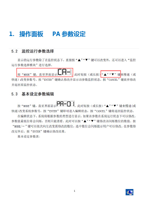
1. 操作面板PA参数设定注意, 报警异常输出DO1 对应PA-16 默认设置为8, 当有系统告警时, DO1输出得电. 开集电极方式输出;或PA-22设置为8, 当有系统告警时, 继电器输出; ( MCOM MC MO)默认情况下, MO一得电, 当出现报警时, MO断开; MC 相反; (注意, 送电初始, 无报警的情况下继电器会有2秒的输出, 此过程不进行检测)设置完需保存参数,, 否则断电后恢复原始值; PA-16默认8 , 对应漏电报警 .2. 异常报警CA状态监控CA-03 显示当前转速使能信号满足时, 待机显示14.5转,运行状态时, 为负数; 当流量设置10V时, 转速显示负2099转;(PA-09最大转速默认设置2100;电机旋转方向? 反转? 运行时负845 流量改变的情况下, 转速好像没改变.. 低压压力可到达14MPA? 高压压力到达多少?2.1 CA-01 0040 电机温度过热2.2 故障历史查询10次记录在CA-01显示时, 按下ENTER, 然后依次按下来查询最近的10次报警记录3. 保存参数设置4. 最高转速底压底流PA-09 最高转速 1~10000 指定电机最高转速,单位:rpmPD-04 压力环反馈零偏 0~±5000 压力反馈信号零偏软件补偿PD-12 最大压力 0~500 系统能够达到的压力,单位:kgPD-27 底压 0~50 为防止空气进入油路,确保系统最小油压不低于该设置值,单位:kg/cm2PD-28 底流 0~50% 为防止空气进入油路,确保系统最小流量不低于该设置值。
PD-29 压力传感器故障检测时间 0~10000 检测压力传感器故障所需时间,时间越小就越敏感,但可能会导误报,设置为0时取消检测,单位:ms。
PD-30 自动零偏校准 0~1设置为1时启动AI1/2/3模拟输入信号的零偏校准,约1秒钟后校准完成自动恢复为0。
5. 最后一页5004-----1。
星辰科技 SV831DUSBU 8口1U USB KVM开关产品说明说明书

8 Port 1U Rackmount USB KVM Switch with OSD Product ID: SV831DUSBUThe SV831DUSBU 8 Port 1U Rack Mount USB KVM Switch with OSD offers a dependable computer management tool that allows you to control up to 8 USB-connected computers from a single keyboard, mouse and monitor.The KVM switch offers maximum control, allowing you to switch computers using hotkey commands or front panel push-buttons, and offers added configuration options and convenience through an On Screen Display (OSD).A suitable addition to server room operations, the 8 port switch can be rack mounted into 1U of cabinet space, and can be cascaded with multiple KVM switches to deliver control of up to 64 computers from this single switch.The SV831DUSBU only works with specific 2-in-1 VGA and USB cables (sold separately), a listof approved cables are below:6 ft Ultra Thin USB VGA 2-in-1 KVM Cable6 ft Ultra Thin USB VGA 2-in-1 KVM Cable10 ft Ultra Thin USB VGA 2-in-1 KVM Cable15 ft Ultra Thin USB VGA 2-in-1 KVM CableThis product is TAA compliant and backed by a 3-year warranty with free lifetime technical support.Certifications, Reports and Compatibility Applications•Add single console administration to your Co-location/ISP facilitysaving you time and money•Create a scalable, streamlined access solution in your Datacenter or Server Farm•Perfect for manufacturing line computer control, simplifying access to multiple systems•Great for PC test/burn-in computer control saving the desk space required for multiple monitors, keyboards and mice•Monitor multiple systems simultaneously in Software QA labsFeatures•Supports Hotkey and front panel push-button switching•OSD security allows each PC to be password protected•Identify and select computers by names assigned via the OSD menu•Auto-scan function automatically selects computer sequentially •Cascade configuration expands system capability•USB console interface•Plug-and-play system configuration•Supported Wide Screen Resolutions: 1920x1200, 1920x1080, 1680x1050, 1400x1050, 1440x900, 1360x768•Supported 4 : 3 Resolutions: 1920x1440, 1600x1200, 1280x1024, 1024x768•USB Keyboard and Mouse combo supported on one USB connectionWarranty 3 YearsHardware Audio NoCables Included NoDaisy-Chain YesKVM Ports8Number of Monitors Supported1PC Interface USBPC Video Type VGARack-Mountable YesPerformance Hot-Key Selection YesIP Control NoMaximum Analog Resolutions1920 x 1440@60Hz (1920 x 1200@60Hz - Wide Screen)Maximum Cascaded Computers64Maximum Number of Users1MTBF150000 hoursOn-Screen Display YesPort Selection Support Push Button, Hotkeys, and OSD (On Screen Display)Wide Screen Supported YesConnector(s)Console Interface(s) 1 - VGA (15 pin, High Density D-Sub) Female2 - USB Type-A (4 pin) USB 2.0 FemaleHost Connectors8 - VGA (15 pin, High Density D-Sub) FemaleSoftware OS Compatibility OS independent; No software or drivers required Indicators LED Indicators 1 - Green - Power8 - Green - Online PC8 - Red - Selected PCPower Center Tip Polarity PositiveInput Current0.6AInput Voltage100 - 240 ACOutput Current 1.5AOutput Voltage12V DCPlug Type MPower Consumption (In Watts)18Power Source AC Adapter IncludedEnvironmental Humidity80% RHOperating Temperature5°C to 40°C (41°F to 104°F)Storage Temperature-20°C to 60°C (-4°F to 140°F)Color BlackPhysicalCharacteristicsMaterial SteelProduct Depth7.1 in [180 mm]Product Height 1.8 in [4.5 cm]Product Width21.3 in [54 cm]Weight of Product 6.4 lb [2.9 kg]Package Height10.6 in [26.8 cm]PackagingInformationPackage Length22.6 in [57.3 cm]Package Width 3.5 in [89 mm]Shipping (Package) Weight7.3 lb [3.3 kg]What's in the Box Included in Package 1 - 8 Port USB KVM Switch2 - Mounting Brackets1 - Bag of Screws1 - Pack Rubber Feet1 - Universal Power Adapter (NA/UK/EU)1 - User ManualProduct appearance and specifications are subject to change without notice.。
迅成伺服简易说明书
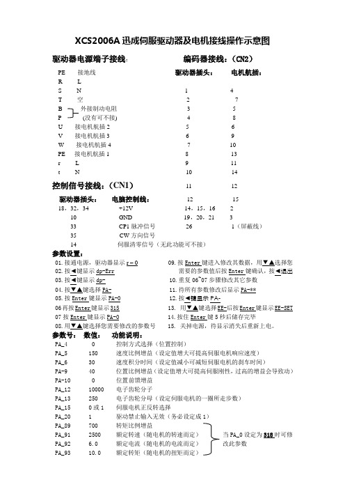
XCS2006A迅成伺服驱动器及电机接线操作示意图驱动器电源端子接线:编码器接线:(CN2)PE 接地线驱动器插头:电机航插:R LS N 1 4T 空 2 7B 外接制动电阻 3 5P (没有可不接) 4 8U 接电机航插2 5 6V 接电机航插3 6 9W 接电机航插4 7 10PE 接电机航插1 8 13r L 9 11t N 10 14控制信号接线:(CN1)11 12驱动器插头:电脑控制线:12 1518,32,34 +12V 14,15,16 210 GND 19,20,21 333 CP1脉冲信号26 1(屏蔽线)35CW方向信号14伺服清零信号(无此功能可不接)参数设置:01.接通电源,驱动器显示r – 0 09.按Enter键进入修改其数据,用▼▲选择您02.按◄键显示dp-Err 需要的参数值后按Enter键确认,按◄退出03.按◄键显示dp- 10.重复06~07步骤修改其它参数04.按▼▲键选择PA- 11.待所有参数修改后显示PA-**05.按Enter键显示PA-0 12.按◄键显示PA-06再按Enter键显示315 13. 用▼▲键选择EE-后按Enter键显示EE-SET 07按Enter键显示PA-0 14.按住Enter键5秒后储存完毕08.用▼▲键选择您需要修改的参数号 15. 关掉电源,待显示消失后重新上电。
参数号:数值:功能说明:PA_4 0 控制方式选择(位置控制)PA_5 150 速度比例增益(设定值增大可提高伺服电机响应速度)PA_6 30 速度积分时间(设定值减小可减短伺服电机的刹车时间)PA-9 40 位置比例增益(设定值增大可提高伺服刚性,过高的增益会导致动)PA-10 0 位置前馈增益PA_12 10000 电子齿轮分子PA_13 250 电子齿轮分母(设定伺服电机的一圈所走步数)PA_15 0或1 伺服电机正反转选择PA_20 1 驱动禁止输入无效(务必设定成1)PA_89 700 转矩比例增益PA_91 2500 额定转速(随电机的转速而定)当PA_0设定为318时可修 PA_92 6.0 额定电流(随电机的电流而定)改此参数PA_93 10.0 额定转矩(随电机的扭矩而定)。
- 1、下载文档前请自行甄别文档内容的完整性,平台不提供额外的编辑、内容补充、找答案等附加服务。
- 2、"仅部分预览"的文档,不可在线预览部分如存在完整性等问题,可反馈申请退款(可完整预览的文档不适用该条件!)。
- 3、如文档侵犯您的权益,请联系客服反馈,我们会尽快为您处理(人工客服工作时间:9:00-18:30)。
NAS 系列交流伺服系统使用说明书特别提示在您第一次接通本伺服系统电源以前,为确保系统能安全、正常、高效地为您工作,请仔细阅读手册中有关使用方面的重要信息。
感谢使用星辰伺服的交流伺服系统!为使本机一直维持良好的运行状态,请将本手册随整机附送给最终用户。
虽然在您的选型过程中,可能已经对本产品有所了解并与本公司的技术人员进行了某些沟通,但为充分发挥本机最佳功能,仍请在使用前,仔细阅读本使用说明书,必要时可与星辰伺服的有关人员联系以获得必要的帮助。
本说明书中,对不同级别的提示、警示、警告采用如下提示符:★一般性的提示警示,如果不按照执行,可能带来设备的损坏警告,如果不按照执行可能带来设备严重损坏、火灾或人身伤害星辰伺服分支机构及技术服务机构:桂林星辰电力电子有限公司市场服务部地址:桂林高新技术产业开发区星辰大厦邮编:541004电话:************,5810692 传真:************ Email:******************上海星之辰电气传动技术有限公司伺服部地址:上海市科技创业中心(徐汇区钦州路100号)2#601-605 邮编:200235电话:************(8线), 64829055 传真:************深圳市星辰激光技术有限公司伺服部地址:深圳市高新区北区清华信息港研发楼A栋3楼邮编:518057电话:*************(15线),26030572 传真:*************目录1.安全注意事项1.1.安装注意事项1.2.运转操作注意事项1.3.保养检查注意事项1.4.关于废弃1.5.其它2.产品的确认和注意事项2.1.产品的确认2.2.伺服电机型号说明2.3.伺服驱动器型号说明2.4.使用前的注意事项3.NAS系列交流伺服系统性能参数3.1.NAS系列伺服系统标准规格配套表3.2.驱动器标准规格及功能表3.2.1.驱动器标准规格及一般功能3.2.2.驱动器使用环境条件及一般技术状态3.2.3.驱动器控制功能及运动性能表3.2.4.伺服电机特性3.2.4.1.N系列电机3.2.4.2.SY系列电机3.2.5.有关工作制的说明4.安装4.1.安装场所和保养4.2.驱动器外形尺寸4.3.驱动器安装4.4.驱动器前级盒的拆卸和安装4.5.伺服电机外形尺寸4.6.伺服电机安装4.7.制动电阻安装5.端口说明及外围电路设计5.1.接线注意事项5.2.外围接线图及端口说明5.2.1.控制接口(44芯排插头)全部功能连接图5.2.2.控制接口(44芯排插头)接口功能表5.2.3.状态通报口的使用5.2.4.模拟量接口的使用5.2.5.转矩环控制运行5.2.6.速度环控制运行5.2.7.带速度限制的位置环控制运行5.2.8.带转矩限制的位置环控制运行5.2.9.带转矩限制的速度环控制运行5.2.10.带转矩偏置的速度环控制运行5.2.11.位置环脉冲给定接口的使用5.2.12.反馈接口(15芯排插头)的连接5.2.13.反馈接口(15芯排插头)端口功能表5.2.14. RS485接口(9芯排插头)的连接5.2.15. RS485接口(9芯排插头)端口功能表5.2.16.动力接口6.操作面板6.1.面板显示说明6.1.1.监视状态下驱动器面板显示状态表6.1.2.运行状态下驱动器面板显示状态表6.2.面板操作说明及编辑状态下面板显示6.2.1.几种典型的操作6.2.2.编辑状态下的显示7.运转7.1.运转前的检查7.2.首次上电和试运转7.3.运转7.3.1.功能、参数设定总表7.3.2.位置闭环运行7.3.3.速度闭环运行7.3.4.转矩环运行8.RS485串行通讯功能8.1.概述8.2.通过RS485串行通讯进行伺服驱动器的运转8.2.1.状态查询8.2.2.修改参数8.2.3.实时控制8.3.TB485-V10通讯协议8.3.1.串口通讯数据格式8.3.2.工作方式说明8.3.2.1.问答方式8.3.2.2.速传方式8.3.3.通讯故障约定及校验说明8.3.3.1.问答方式8.3.3.2.速传方式9.保护功能9.1.设定方法(功能代码显示模式)9.2.功能代码一览表9.3.功能说明10.故障确认11.保养和检查11.1.保养和检查时的注意事项11.2.检查项目11.3.兆欧表测试11.4.零部件的更换安全注意事项1.安全注意事项1.1.安装注意事项★ 安装环境:使用温度伺服电机 -20℃~+40℃伺服驱动器 -10℃~+40℃保存温度-25℃~+65℃环境湿热伺服电机 95%,30℃,不结露伺服驱动器 90%,30℃,不结露标准高度海拔2000m以下(2000m以上,每上升1000m降容20%)★ 请将电机和驱动器安装于通风良好的场所。
★ 请勿将伺服驱动器安装于有粉尘、腐蚀性气体、盐雾、油雾、水滴的场合。
安装电机时,切勿敲击电机轴伸,以免损坏轴上的精密部件或导致精度下降!本系列伺服电机连续满负荷运行时,表面温度可能达到100℃,该温度在设计允许范围内,可正常运行,但请注意将电机安装于人和动物不易触及的场合,避免烫伤。
外置制动电阻在电机频繁制动时,可能会升至很高温度,请注意散热通道通风良好。
推荐放置于控制机柜外部(如顶端通风机出风口)并进行可靠地防护。
必须安装在机柜内部时也应安装在顶端通风机出风口附近,并远离其他器件。
请勿将电机、制动电阻及驱动器安装于可燃物附近,否则可能引起火灾。
搬运电机时,切勿提拉航空插头连接器件,以免损坏电气连接器件,并导致电机坠落和造成伤害!请可靠连接好接地线,并请专业人员进行布线作业,以免造成触电或火灾事故。
1.2.运转操作注意事项★ 首次上电前务请仔细检查所有外接线,避免因接线错误带来重大事故!首次接通使能请尽可能使电机空载,并随试运转情况时准备关断使能。
请另外设置急停开关。
请勿采用合、分电源的方法使伺服系统启、停工作,应采用使能操作启、停。
切勿在断开动力电源时保持使能长时间接通,否则可能损坏设备!1.3.保养检查注意事项除了经过培训的修理人员,请勿进行检修和部件更换等工作!检修时请使用绝缘防护工具,否则可能造成触电事故或人身伤害!进行保养检查时,请在断电后并确认直流母线的P、N之间电压降到10V以下后方可进行作业。
1.4.关于废弃产品内部含有电解电容、集成电路、环氧板等构件,需要废弃时请按工业废弃物处理,否则可能造成人身伤害和环境污染。
1.5.其它对于本产品偶然故障可能引发重大事故或带来重大损失的工作场合,请另行考虑设备的安全、保护装置,制造商、销售商、服务商均不能承担由于伺服系统故障而带来的除本伺服系统以外的关联损失和连带责任。
请绝对不要私自对产品进行改造,否则可能导致触电、故障、烧毁、火灾等!请不要更换未经供方书面认可的反馈元件,否则可能引起系统损坏!2. 产品的确认和注意事项2.1. 产品的确认本套伺服系统的装箱单置于伺服驱动器包装箱内,由于运输过程中不可预见的情况,开箱后,请按装箱单仔细核对以下几项内容:(1) 核对伺服驱动器、伺服电机上的铭牌,确认型号是否准确无误? (2) 产品外观是否完好无损?(3) 接插件、使用手册、保修单、合格证是否齐备?伺服电机产品标牌伺服驱动器产品标牌2.2. 伺服电机型号说明额定转速代号三相200VAC 5K517K 功率等级代号三相340VAC4电机电压17kW 5.5kW 22000rpm 1500rpm 3000rpm 301520190 N 5K5 4 - 15 M N 1机座号电机系列代号N SY M 工业品OEM 系列代号军品速度位置磁感应器反馈无制动器带制动器带U V W 的增量编码器反馈设计序列号N 反馈方式代号M A Z S1S2 30min S2 5min7.5kW23.8kW 11kW 34kW2.3. 伺服驱动器型号说明输出最大电流有效值产品结构形式代号3510035A 100A NAS 4 C 3 35 M T1A 反馈方式M 产品系列代号动力电源电压等级代号单相或三相220VAC 三相380VAC第三代设计代号24带U 、V 、W 光电编码器反馈特殊定货编号T1~Tn 速度位置磁感应器反馈型号后缀空缺标准品军品MASNAS工业品2.4.使用前的注意事项务请在符合标准的环境(如温度、湿度、振动、尘埃等)下使用;初次运转时,请仔细检查布线是否正确。
特别应检查电源线(输入)、光电编码器/速位磁感器反馈线(输入)和电机线(输出)有无接错,否则会损坏驱动器;伺服系统的使用寿命受工作或存储场所环境温度的影响很大,因此使用时合适的环境温度是延长使用寿命的重要因素;当驱动器安装在控制柜内使用时,请充分考虑留有航空插头的插接空间,并保持良好的通风;在驱动器和电机之间,原则上不要设置电磁接触器,否则在驱动器运行过程中,打开或关闭电磁接触器都会产生拉弧。
不得已采用电磁接触器时,应确保电磁接触器动作时,伺服驱动器的使能保持关断状态;驱动器出厂前已经过严格的绝缘耐压测试,请用户不要自行对驱动器进行绝缘耐压测试,否则可能造成驱动器损坏!必须检测时,请在本公司专业人员指导下,按本说明书(11.3兆欧表测试)的方法进行操作。
3.NAS系列交流伺服系统性能参数3.1.NAS系列伺服系统标准规格配套表驱动器型号电机型号额定功率(kW)额定转速(rpm)额定扭矩(N.m)伺服系统配套最大扭矩*(Nm)130N7502-20□N10.752000 3.67.2130N1K12-20□N1 1.12000 5.811.6 NAS2C412□130N1K52-15□N1 1.520007.214.4130N2K22-20□N1 2.2200010.521130N3K02-20□N13200014.428.8190N4K02-20□N14200019.339 NAS2C330□190N6K52-20□N1 6.520003143.5190N5K54-15□N1 5.515003570190N7K54-15□N17.5150047.866 NAS4C325□190N8K54-30□N18.530002733.6190N7K54-15□N17.5150047.892190N8K54-30□N18.530002747 NAS4C335□190N11K4-15□N111150070103190N8K54-30□N18.530002754190N11K4-15□N111150070140 NAS4C250□230N17K4-15□N1171500110161.7230N17K4-15□N1171500110220 NAS4C270□280N22K4-15□N1221500140196280N22K4-15□N1221500140280 NAS4C1100□280N30K4-15□N1301500191281280N30K4-15□N1301500191382320SY45K4-15□N1451500286.5343450SY55K4-15□N1551500350420 NAS4C1140□450SY75K4-15□N1751500477.5477.5*注:受所配伺服驱动器最大输出电流限制,表中伺服配套最大扭矩一栏列示的数据不一定是电机的最大输出扭矩。