胥工XD+XSP使用说明书(多管)
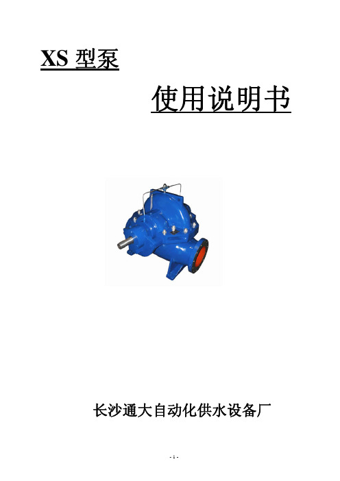
XS型泵说明书
6. Type XS pumps look beautiful with visible lines adopting industrially designing.
COST ADVANTAGE:
1. The efficiency of XS pumps are 2%~3% higher than the same type pumps due to adopting advanced
-8-
XS 型谱图(二)(selectiom charts of XS pump)
-9-
XS 型谱图(三)(selectiom charts of XS pump)
- 10 -
性能参数(Performance Data)
泵型号(Type)
流量 (Capacity)
80-210
80-270 80-370 100-200
support at both sides, thus they can be widely used. ⒉ The pipelines arrangement of type XS pump looks simple and beautiful due to inlet and outlet at a
XS 型泵
使用说明书
长沙通大自动化供水设备厂
-1-
产品概述
General XS 型泵为新一代高性能单级双吸中开式离心泵,主要适用于自来水厂、空调循环用水、供热管网
系统、建筑供水、灌溉、排水泵站、电厂、工业供水系统、消防系统、船舶工业、矿山给排水等输送液 体的场合。是 SH、S、SA、SLA、SAP 型中开双吸泵的全面换代产品。
47.5 39.0 36.0
41.0 33.5 30.0
#XP系列电动执行器说明书
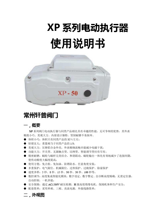
XP系列电动执行器使用说明书常州轩普阀门一,概要XP系列阀门电动执行器与同类产品相比具有卓越的性能,无可争辩的优势,其外表精致小巧、美观大方,内部设计独特,坚韧耐磨不易损坏。
●体积小巧:体积只有同类产品的35%左右;●轻便宜人:重量相当于同类产品的1/3;●美观大方:压铸铝合金外壳,外表精细流畅并能减少电磁干扰;●功能大方:开关型、无源触点型、比例型、智能调节型应有尽有;●精密耐磨:蜗轮与蜗杆完美结合,和谐联动,蜗轮输出一体化有效地减少了连接间隙,使传动精度大幅度提高;●使用方便:免点检、免加油、防锈防水、任意角度安装;●多重保护:电气限位、机械限位、过热保护、过载保护、除湿保护●速度多样:5秒、8秒、15秒、30秒、50秒、100秒等;●数控调节:高度集成智能化模块,数字设定、数字整定、自诊断高度精确,无需定位器,自动控制,一机多能;●安全保障:通过AC1500V耐压检测,H级高度绝缘电机,保障机体和生产安全;●配套简单:采用单相、三相、直流电源,外接线路简单;二,外观图5零 件 名 称1 箱体2 开度计3 电缆夹头4 手动部橡胶塞5 输出轴6 减速盖7 电气盖8 接线盖9 手动操作处三,外观尺寸图9080686-M88-M67260D 7063121212104594520-5XP24680S H UT OP E N 123424680S H U TO P E N988286704-M64-M 8701545°121224680S H U TO P E N-25/50153269063XP115266352-10/16XP13 5118106848-M102310245°1524680S H UT O P E N148118106841704-M 106-M1230151524680S H U TO P E N四、回转型阀门电动执行器特性参数表机型功能XP-5XP -10XP -16XP -25XP -50XP -100XP -200电源 AC220 56/60HZ(please explain if need AC24V ,AC110V ,AC380V ,DC24V ,DC220V订货请说明)力矩 50N.M 100N.M 160N.M 250N.M 500N.M 1000N.M 2000N.M时间 5,10,30 5,15,30,60 5,15,30,60 5,15,30,60 5,15,30,60 60 100 电机 15W/H 23W/H 23W/H 50W/H 90W/H 100W/H 100W/H 工作电流 0.25A 0.6A 0.7A 0.8A 1.2A 1.3A 1.3A 重量 2.5KG 3.7KG 3.7KG 6.8KG 8.0KG 12KG 12KG 转动角度 0 º~360 º 0 º ~90 º环境温度 -30ºC~+60 ºC 耐压值 1500V AC/1分钟防护等级 IP-65 限位电气机械156956126-100/200XP手动操作附带手柄安装角度任意角度注:时间指从0°~90°形成所需时间转动角度:指形成的角度可调范围选装功能:1.加热除湿器2.过扭矩保护器3.4-20mA, 0-10V,1-5V智能调节型五,电路图M654321ACShut lam pOpen lampS hutO penM654321AC XP-xx 开关型XP -xx无源触电型M654321A CShut-ComOpen-Shu tOpe nNcM987654321K CT AWVUK OSCK CKOK CK OS Oshut-s ignOpe n-signComXP -xx 开度型(R)XP -xx AC380V4-20m A 220VAC 4-20m A OU TINPOW E R +-+NLRO RVRS GNDSHUT OPENCOMR 1R 2100%0%- 654321- ++ -MC l o s e -s i g nO p e n -s i g n c o mO p e n s h u tXP -xx 调节型 XP -xx 直流线路图 请分开连接电动执行器的动力线路,切勿用同一接点去控制数台电动执行器,一面造成失控和电机过热.六,安装●安装场所可以是室内,室外,地下。
XDO中文操作维护手册
2.3.1 选件.................................................................................................................................... 2-2 2.4 安装考虑....................................................................................................................................... 2-2
3.3.1 可回收包装........................................................................................................................ 3-2 3.4 设备搬运....................................................................................................................................... 3-2 3.5 开箱............................................................................................................................................... 3-2
30XAXQ电器说明书(新版)
4.10.1 4.10.2 4.10.3 4.10.4 4.10.5 4.10.6 4.10.7 4.10.8 4.10.9
标准机组菜单................................................................................................................. 15 A 回路模拟值菜单 .......................................................................................................... 16 B 回路模拟值菜单 .......................................................................................................... 16 C 回路模拟值菜单 .......................................................................................................... 17 A 回路离散值菜单 .......................................................................................................... 17 B 回路离散值菜单 .......................................................................................................... 18 C 回路离散值菜单 .......................................................................................................... 18 设定点菜单..................................................................................................................... 19 输入菜单......................................................................................................................... 19
XQS-D吸附式氢气干燥器使用说明书
XQS-D A B吸附式氢气干燥器使用说明书扬州电力设备修造厂江新中科技有限公司V.06安全该机电设备是在工业强电流的条件下使用的。
在操作中,该设备上有些裸露零件带电,同时有些零件能够运动或转动,都是很危险的。
因此,未经许可拆下所需的罩盖,不合理的使用,不正确的操作或不合适的维护,均会造成严重的人身伤害或损坏设备性能。
为了设备的安全,必须保证:——仅允许有资格的人员对这些机械和设备进行作业。
——无论何时,在上述有资格的人员对该机械和设备进行作业时,他们都应具备有这些机械和设备的操作说明书或其它产品文件,以便按说明书的要求执行。
——严禁没有资格的人员对该机械和设备进行作业或在其附近进行作业。
前言“XQS系列吸附式氢气干燥器”(以下简称“干燥器”)采用双塔交替吸附再生,可连续不间断地对气体干燥去湿。
干燥剂的再生采用压力下再生,不消耗再生气,既节约再生气体又安全简便。
该“干燥器”具有吸附容量大、性能稳定、环保、节能等优点。
“干燥器”备有置式循环风机,当被处理系统中气体无流量或气体流量小的情况下,增大气体流量,尤其在发电机停机情况下,气体干燥效果不受影响。
干燥器还设计安装了油过滤器,可在气体干燥前先将气体中的油蒸汽去除,既保证了去湿效果又可延长吸附剂的使用寿命。
“干燥器”的干燥塔、管道、阀门等均为1Cr18Ni9Ti不锈钢材料制作。
干燥器主要适用于容量为200~1000MW“氢冷发电机组”。
干燥器的运行是由SIEMENS(西门子)SIMA TIC S7-200可编程控制器控制,可按照所编制的程序控制去湿装置运行。
电气控制箱控制面设计有触摸式液晶显示屏,直接显示去湿装置系统运行情况,并可通过液晶显示屏上的触摸按钮选择各种工作模式。
氢气进、出口设计有湿度传感器,直接显示进、出口氢气的“露点”值。
干燥塔的再生设计有加热温度控制系统,可自动显示和控制干燥塔干燥剂吸收层的再生温度,以便获得干燥剂的最佳再生效果。
电气控制系统具有“加热器”、“运行”、“电机”故障报警等保护功能。
XD中文说明书
(型号 CMH-2301)
焊接电源 输入侧电缆
气体流量计 气管
控制电缆(6芯) 焊枪侧电缆 (请将其于焊接电源的+相连接。)
接地
送丝机 (型号CMX(L)-2302)
遥控盒(置于送丝机上)
焊枪
工件
工件侧电缆
接地
4.2 附件 名称
机种
XD200
XD350
XD500 数 量
栓遥形控保盒险 玻璃管保险 根角六螺弹光圆角螺头母垫垫栓螺栓
*钢瓶倾倒会引发人身事故。 *钢瓶内装有高压气体,错误使用会引发人身事故。 ●关于如何使用钢瓶,请依照法规与贵公司内部基准。 ●气体流量计请选用本公司附件或本公司推荐产品。 ● 前 流量 在使用 ,请阅读气体 计使用说明书并遵守注意事项。 ●请勿高温曝晒气体钢瓶。 ●请使用专用的支架固定气体钢瓶。 ●打开气体钢瓶阀门时,请勿将脸部靠近出气口。 钢瓶 罩好 罩 ●不使用气体 时,请务必 保护 。 ●请勿将焊枪挂在气体钢瓶上、勿使电极接触钢瓶。 旋转 成 , 定 注意 接触 部位会造 伤害 务请遵守以下规 。
用语予以警告,此标识符及警告用语在电焊机中亦表示相同的意思。
提请注意标识符
警告用语
内Hale Waihona Puke 容高度危险误操作后极度危险,可能引发重大人身事故。
危险
误操作后危险,可能引发重大人身事故。
注意
误操作后发生危险,可能引发中度伤害或轻伤。或只遭受物 质损失。
·注意标识符表示一般情况。 ·上述重大人身事故是指失明、外伤、烫伤(高温、低温)、触电、骨折、中毒等,会遗留后
场 近 灭火 防万 ●请在焊接操作 所附 放置 器,以 一。
-5-
No. C0049
2. 敬请遵守的安全事项(续)
鑫国XD调节仪说明书
鑫国XD调节仪说明书鑫国XD调节仪说明书内容是指XD调节仪的使用说明书。
在使用XD调节仪之前应该阅读有关介绍、使用方法、注意事项、性能要求和使用注意事项等方面。
XD调节仪说明包括说明书和使用说明两部分。
说明书适用于大多数XD系列仪器。
•一、仪器名称: XD调节仪(型号)XD调节器是一种XD测量仪器。
它能测量温度、压力、速度和电流的线性变化。
由具有数字显示功能的液晶显示器组成。
•二、适用范围:本品适用于各种表面处理工艺、电化学分析、冶金、矿山、建材、建筑、纺织服装等行业中的磨粉、喷砂,电镀,喷涂,表面处理等工序。
本品适用于各种粉末状涂料,金属,橡胶,塑料等各种表面处理工艺及各种表面处理后分析工艺,产品具有体积小、精度高、操作简单等特点。
本品适用于各种表面处理工艺前处理,粉末处理后分析工艺及各种表面处理工艺后分析工艺。
适用于各种表面处理工艺后的产品分析检测。
本品采用先进的XD技术、信号放大技术和自动检测技术。
具有自动测量速度等功能。
•三、使用说明:1、使用说明:开机后首先要确保机器的电源电压是不低于20 V,并应经常检查仪器各部分是否良好,如有异常应及时处理。
2、使用说明:开机后先进行X射线波长扫描,然后测量仪器内各元件的X射线波长对应参数和仪器的X射线波长,并将参数对齐进行处理。
3、使用说明:调整XD调节仪工作频率及X射线速度所需时间应根据样品种类来决定。
4、操作方法:操作仪器时应保持仪器清洁及避免撞击,或撞击。
5、使用程序:仪器按功能及使用条件配置仪器设定参数后保存并设定工作参数,仪器工作完成后进行X射线能量测量。
•四、使用方法XD调节仪有两种连接方式。
分别是电流表连接方式和压力补偿连接方式。
调节电压或电流表的温度可在使用过程中,通过仪器操作完成,不需要使用外部电源。
XD调节仪没有外部电源接线端子,不需要连接外部电源使用,只需要将调节仪与电流表连接即可。
•五、注意事项:仪器的外壳应与仪器的其他部分分开,以避免在检查过程中发生误操作,或仪器损坏。
SAF PLASMA 自动焊接器产品说明书

0704/18G 138G 137G 136G 139AUTOMATIC PLASMA WELDING in the stainless steel boiler maker industryWHAT MUST BE ACHIEVED ?SAVINGS ? Rapidity of operation, low deformation to avoid or reduce the reconforming post operations, low reinforcement to reduce or suppress polishing operations, keep the original chemical analysis of the base material to garantee corrosion characteristics, good visual aspect of the welds since most of the welds are more and more visible. It is a quality criteria, repeatibility of the quality obtained.G 86In the constant search for optimal productivity, every industry must strive to reduce production time while maintaining extremely high quality. In the case of plasma welding, unlike the tricathode process, the multiplication of torches would have little effect on the performance levels.Nevertheless, a solution exists for increasing speeds by 30 to 50 % in comparison with a single torch : PLASMA + TIG process.Thanks to this technique, the PLASMA arc melts the joint throughout its thickness, while the TIG arc, equipped with a magnetic oscillation system and additional filler metal prepares the final appearance of the surface. This yields results that are perfectly suited to the specifications of speed and quality. SAF , an innovative specialist in TIG and PLASMA welding, naturally offers installations combining these techniques, which are particularly suitable for production of large stainless steel vessels. Nonetheless,certain strict criteria are required for ensuring the profitability and the technical feasibilityof these materials. These criteria may be summed up as follows : manufacture of stainless steel tanks from 3 to 8 mm thick, with a welding length of at least three meters, or parts with a diameter greater than 2200 mm.TOP QUALITY RESULTS AND INCREASED PRODUCTIVITY Initial plate preparation/fit-up greatly reduced by suppression of bevel up to 7 mm.Reduction of welding times compared to manual welding (up to 4 to 5 times).A garanted regular penetration thanks to the «key hole» technique on all but joints with TIG pre-tacking. A very high quality weld in regard to most stringent controls. It eliminates hazards of lack of penetration at the beginning of welds as well as the systematic delicate repairs after grinding of beginnings and ends of welds. A guaranted reproductibility,thanks to memorization *of complete welding parameters programs (simply defined by material,diameter and thickness).High quality finish on circular welds thanks to the automatic key hole closure system*.*PLASMA with microprocessor installation only.G 1370725/10G 2000725/08Welding current (100 %)30 - 350 A DC 100 % 3 - 300 A DC (±1 %)500 A DC 100 %Pulsed current frequency10 Hz max (option) 1 - 500 Hz 10 Hz max. Primary voltage (50 - 60 Hz)380/400/415 V 220/230/380/400/415/440/500 V 220/380/415 V or 380/440/500 V Supply current (380 V)39 A 17.6 A 36 A Plasma pilot arc12 A 1 - 25 A adjustable 15 A Gas circuitswith built-in gyrometers with built-in gyrometers gyrometers in the controls Welding current controloption yes Process controlyes option no Dust protection- 2 interchangeable filters -Dimensions (h x w x d)940 x 517 x 820 mm 1225 x 700 x 790 mm 1320 x 670 x 780 mm Weight175 kg 245 kg 450 kg Cat. NumberTIG :9121-1049/50/51 (1)9114-05569114-0532plasma :9121-1046/47/48 (1)9114-0533Insulationclass H class H class H ProtectionIP 23IP 23IP 23Torch cooling unit nooptional for TIG no Thanks to its characteristicsand its high degreeof automation whick makesit relatively easy to master,the PLASMA processis now commonly usedin the boiler making industry and SAF since 1965, has installed more than 800 installations throughout the world. SAF offers now a wide range of turn key welding installations,but it has to be choosen carefully according to the work to be done.It involves 3 levels of sub assemblies :•the PLASMA welding equipment,• the support structure of the PLASMA equipment,• the positionning equipment to rotate the rounded sheetsand/or the seamer bench.THE PLASMA WELDING INSTALLATION FOR THE BOILER MAKER INDUSTRY BUFFALO TIG or plasma installation.Programmation and adjustments by potentiometers.Direct current.350 Amps (100%).NERTAMATIC 300 TR This high-technology power source offers a totally regulated welding current facility at frequencies from 1 Hz to 500 Hz **.NERTINOX TH 500 Thyristor power source.Programmed and adjusted by potentiometers.500 A DC (100 %).**Pulsing the PLASMA arc currentat two levels (e.g. 100-200 A)produces a very high levelof confinement of the energyin the arc (the electromagnetic pinch effect combiningwith the pneumaticand mechanical confinementimparted by the nozzle).It offers great operator comfortcombined with better penetrationcontrol and appearance (back of weld).POWER SOURCES1202-501202-45Q -1311-05Do not operate the key-hole closure at the end of weld bead.(1)Harness length 10/17/22 m0704-15Q -1422-012264-102264-011202-473670-421202-49S A F r e s e r v e s i t s e l f t h e r i g h t t o e m b o d y m o d i f i c a t i o n s w i t h o u t p r i o r n o t i c e . T h e i l l u s t r a t i o n s , d e s c r i p t i o n s a n d c h a r a c t e r i s t i c s a r e g i v e n f o r i n f o r m a t i o n o n l y a n d d o n o t e n g a g e t h e r e s p o n s i b i l i t y o f t h e c o n s t r u c t o r .© S A F - 1515-47760006S 01 E d . 4Q B: 1590P hotosS A F : R o c s k a y - F r a n ço i s SAF - 13-17, RUE D’EPLUCHES 95310 SAINT-OUEN L’AUMÔNE - FRANCE TEL. : + 33 1 34 21 33 33 - FAX : + 33 1 34 21 31 30SAF WELDING PRODUCTS LTD - LOW MARCH - LONDON ROAD DAVENTRY - NORTHANTS NN11 4SD TEL. : 01327 705511 - TELEFAX : 01327 701310Email:***********************Internet : DISTRIBUTOR’S STAMP。
PHILIPS IntelliVue XDS 應用程式 使用说明

病患監視使用說明IntelliVue XDS 應用程式版本H.xx.xxPhilips Medizin Systeme Boeblingen GmbH Hewlett-Packard-Str. 271034 Boeblingen德國© 版權所有 2011Koninklijke Philips Electronics N.V.保留所有權利文件號碼4535 642 56881 A 版2011 年 3 月於德國印製*453564256881*1IntelliVue XDS 應用程式簡介5XDS Remote Display5XDS LaunchPad6XDS Printing Service6XDS Infrastructure Service72使用 IntelliVue XDS Remote Display9簡介9設定組合10使用者介面慣例10遠端操作病患生理監視器11在病患生理監視器上檢視畫面11啟動 XDS Remote Display11選擇不同畫面12選擇不同的病患生理監視器13返回預設的病患生理監視器15移動病患生理監視器時中斷連線15建立與管理畫面16變更畫面大小與優先順序17啟動其他應用程式19為 XDS Remote Display 進行疑難排解19 PC 執行資源不足20設定 XDS Remote Display21離開 XDS Remote Display21PC 關機21 3使用 IntelliVue XDS LaunchPad23簡介23設定組合23使用者介面慣例23啟動 XDS LaunchPad24在 iPC (IntelliVue MX 系列病患生理監視器) 上啟動24在外部 PC 上啟動24選擇執行中的應用程式25啟動其他應用程式25從病患生理監視器啟動應用程式254使用 IntelliVue XDS Bedside Device27簡介27啟動 XDS Bedside Device27電源中斷後恢復運作27關閉 XDS Bedside Device28為 XDS Bedside Device 進行疑難排解28設定 XDS Bedside Device2935在 iPC 上使用 IntelliVue XDS 應用程式31簡介31在 iPC 上使用 XDS 應用程式31使用輸入設備31前個畫面按鍵31當 iPC 視窗大小改變時31 6附錄 A33IntelliVue XDS 應用程式通訊軟體33 7附錄 B35安全與認證資訊35電磁相容3541 IntelliVue XDS 應用程式簡介IntelliVue XDS 應用程式是一套建於Windows 架構的電腦應用程式,可安裝於以下設備中使用:•MX 系列病患生理監視器的整合式 PC (iPC)•IntelliVue XDS Bedside Device (醫療級 PC),或•其他 PC。
HFXD手机电子控制器商品说明书
ContentsHFXD CATALOG E-ELSE-CC001-E—August 2021 2INTRODUCTION . . . . . . . . . . . . . . . . . . . . . . . . . . . . . . . . . . . . . . . . . . . . . . . . . . . .3SPECIFICATIONS . . . . . . . . . . . . . . . . . . . . . . . . . . . . . . . . . . . . . . . . . . . . . . . . . . .4SOFTWARE OPTIONS . . . . . . . . . . . . . . . . . . . . . . . . . . . . . . . . . . . . . . . . . . . . . . .5EXAMPLES . . . . . . . . . . . . . . . . . . . . . . . . . . . . . . . . . . . . . . . . . . . . . . . . . . . . . . . .6MOUNTING DIAGRAM – REMOTE MOUNTED . . . . . . . . . . . . . . . . . . . . . . . . . . .7MOUNTING DIAGRAM – COIL MOUNTED . . . . . . . . . . . . . . . . . . . . . . . . . . . . . .8WIRING RECOMMENDATIONS . . . . . . . . . . . . . . . . . . . . . . . . . . . . . . . . . . . . . . .9PRO-FX CONFIGURE . . . . . . . . . . . . . . . . . . . . . . . . . . . . . . . . . . . . . . . . . . . . . . .10RESOURCES . . . . . . . . . . . . . . . . . . . . . . . . . . . . . . . . . . . . . . . . . . . . . . . . . . . . . .11HFXD CATALOG E-ELSE-CC001-E—August 2021 3IntroductionFeatures and benefitsThe HFXd is a compact, solenoid or remotely mountable controller designed for closeintegration with valve and pump products. This control unit features closed- and open-loop control capabilities, 2 inputs and 2 outputs (configurable), and CAN bus protocols in a rugged housing designed for on- and off-road mobile equipment.There are two software options available for HFXd. The first option is to use the pre-programmed applications installed on HFXd to drive typical solenoid- operated hydraulic products. With these pre-programmedapplications, no programming of the HFXd is required. Eaton’s Pro-FX™ Configure software is used to configure settings based on the product HFXd is controlling. The second software option is to program the HFXd using Matlab/Simulink. A Matlab Support Package is available to simplify developing code for deployment onto an HFXd.Pre-programmed applications: 102EC20100A Matlab Support Package 102EC20102A Small but powerfulIn HFXd’s small package is a powerful 32 bitmicroprocessor with floating point support, 16 MB Flash, and CAN communication. Both HFXd variants can read 2 sensors and control 2 independent solenoids up to 2.5A each.Streamline setup without programmingSoftware applications to control many electrohydraulic products are pre-programmed into HFXd. Just set up the pre-programmed application based on the product HFXd is controlling to get up and running quickly.Flexibility through Matlab/SimulinkIf a custom application is required, it can be built in Matlab/Simulink using the HFXd Matlab Support Package. The application is then flashed to HFXd using Pro-FX Configure.Develop smart solutionsConvert Eaton electrohydraulic products into smart solutions that can communicate over CAN bus and provide diagnostic information about the product’s status. Using CAN simplifies wiring and can reduce material usage by up to 90%.Ruggedized for mobile useHFXd is rated to IP69k with an operating temperature of -40°C to 85°C (-40°F to 185°F) and a range of input voltages.Repurpose outputs if not neededHFXd has 2 dedicated inputs and 2 outputs that can individually be reconfigured to be additional inputs. This flexibility allows for monitoring 3 sensors if only one coil is being driven or 4 sensors if no outputs are needed.SpecificationsTechnical dataDimensions L: 3.35 in (85 mm) x W: 1.89 in (48 mm) xH: 1.3 in (33 mm)Weight 3.3 oz (94 grams)Storage temperature range -40°C to +125°COperating temperaturerange-40°C to +85°CIP rating IP69kOperating altitude0-4000 mSupply voltage8-32 VDC, nominal operation @ 12/24 VDC Peak supply voltage36 VDCMaximum load current6A @ 85°CStandby current 12/24 VDC5mA @ 12/24 VProcessor32 bit, 240 MHz, Expressif ESP32 module(dual core Xtensa 32-bit LX6 microprocessor) ROM448 KbyteSRAM520 KbyteExternal flash & SRAM16 MbyteElectrical connectorsMain connector Deutsch DTF13-12PB CommunicationsCAN interface 2.0A, 2.0BBaud rates125 kb/s, 250 kb/s, 500 kb/s, 1 Mb/s Protocol J1939Default address44Default baud rate250 kb/sSoftwareProgramming options Pre-programmed applications, Matlab/SimulinkSensor supplyNumber of sensor supplies 1Sensor supply outputvoltage5 VDCSensor supply maximumcurrent50 mA @ 5 VDCStandardsTemperature environment SAE J1455Environmental SAE J1455Salt spray J1455 Section 4.3.4Vibration J1455 Section 4.10.4.2Drop J1455 Section 4.11.3.2Shock J1455 Section 4.10.5Conducted immunity SAE J1113, EN 61326-1, 2004/108/EC Radiated immunity SAE J1113, EN 61326-1, 2004/108/EC Conducted emissions CISPR 25, EN 60945, 2004/108/EC Radiated emission CISPR 25, CISPR 11, EN60946 Environmental directives RoHS, REACHCertificationsMarkings CE mark, UKCA mark, E mark, FCC mark InputsNumber of channels2, but outputs can be configured as inputs forup to 2 moreType Software configurable to analog, digital orfrequency inputsDigital input Digital lowInput frequency850Hz +/-20% @ -3dbSwitch-on level 3.5VSwitch-off level 1.4VFrequency input Digital lowInput frequency0 Hz - 50 kHzSwitch-on level 3.5VSwitch-off level 1.4VAnalog input0 - 5 V (absolute & ratiometric), 0 - 10 V,0 - 32 V , 0 - 20 mA, thermistor (softwareconfigurable)Resolution 12 bitsAccuracy+/- 0.2 % FS (0-5 VDC mode), +/- 1 % FS (allother modes)Short circuit protection IntegratedVoltage input 0 - 5 VInput frequency 850Hz +/-20% @ -3dbVoltage input 0 - 10 VInput frequency 1.5kHz +/-20% @ -3dbThermistor inputInput resistance 10 kΩ pull upSample frequency 1 kHzAccuracy+/-1%Current input 0 - 20 mAInput resistance200 OhmInput frequency 850Hz +/-20% @ -3dbOutputsNumber of channels2, or can be configured as inputsDigital output High sideMax load current 2.5APWM output currentfeedbackHigh sideDiagnostics Open/short circuit protectionPWM frequency0.05 Hz – 2 kHzDither frequency Software configurableDither amplitude Software configurableControl range0.05 - 2AControl resolution20 mAFly back protection IntegratedDuty cycle resolution0.01% @ 250 HzHFXD CATALOG E-ELSE-CC001-E—August 2021 4HFXD CATALOG E-ELSE-CC001-E—August 2021 5Software optionsPre-programmed applications for driving hydraulic productsMatlab/Simulink for custom applicationsTo enable quick setup with electrohydraulic products, HFXd can come with a set of pre-programmed applications. Each application has configurable settings to allow for tuning of the controls to a specific machine. These settings are configured using Pro-FX Configure for HFXd. All pre-programmed applications include:• Command via direct inputs or CAN message • Configurable ramp and filter• Closed-loop current control with dither • Configurable fault detection and response•Overrides for commissioning and troubleshootingAdditional features available for pumps include:• Open- or closed-loop displacement control • Electronic torque limit, fixed setting• Electronic power limit, speed-dependent setting • CAN broadcast of pump flow• Electronic automotive drive with direction control •C-Steer or S-Steer for dual path applicationsCustom applications can be developed for HFXd using the HFXd Matlab Support Package (MSP). Simulink blocks are provided for interfacing with HFXd’s I/O, including blocks for tasks, CAN, reading sensors, current outputs, and storing calibratable parameters in memory.Settings created in a custom application can then be configured using Pro-FX Configure. Custom user interfaces for Pro-FX Configure can be developed with Pro-FX Configure Builder. Refer to Pro-FX Configure documentation for more detailsHFXd’s MSP requires Matlab version 2020a and the Matlab Embedded Coder toolbox.Refer to the HFXd MSP documentation for more details.The table below summarizes the available pre-programmed applications. For more details, refer to HFXd’s pre-programmed applicationsdocumentation.Available Pre-programmed Applications Example Eaton ProductsSolenoid Valve(s)*Available options include open-loop or closed-loop control, torque or power limiting†Electronic automotive drive or dual path propel also availableExamplesSwash angle sensorSLV20HFXD CATALOG E-ELSE-CC001-E—August 2021 7Mounting diagram – remote mountedRefer to the HFXd Installation and Service Manual for mounting recommendations.Available Products SoftwareProduct Number Pre-programmed applications 102EC20100A Matlab Support Package102EC20102AMain Connector Type:Deutsch DTF13-12PB Pin Function1System Power Positive 2System Power Negative 3Output PWM1 2.5A +4Ignition Input 5CANH 6CANL7Channel 1 Input 8Channel 2 Input 9PWM Negative10Output PWM2 2.5A +11Gnd 125V outHFXD CATALOG E-ELSE-CC001-E—August 2021 8Mounting diagram – solenoid mounting with bracketExample of HFXd mounted with required bracket onto a solenoid coil. Refer to HFXd’s Installation and Service Manual for mounting instructions.Available Brackets Bracket Part Number Coil Part Number 6048402-001A-4059-0066048402-002A-4059-0016048402-003A-2508-XXX 6048402-004A-2507-XXXWiring recommendationsUse the following recommended wiring practices Array when installing and using the controller:• E nsure correct and adequate single point ground to preventground loops.• U se twisted or twisted shielded pair cable for CAN per theapplicable standard ISO11989-2.• C onfirm that the CAN network is properly terminated using120Ω resistors.• E nsure the appropriately sized conductor cross sectionis specified for the intended load current in the harnessdesign.• P lease review individual overcurrent shutdown values in theconfiguration and use the correct wire gauge conductor toaccommodate maximum load current configured.• M ake sure that voltage drops are kept within reasonablelevels under maximum continuous load conditions e.g. 1volt on 12-volt systems and 2 volts on 24-volt systems.• V erify that the harness is constructed to meet the needs ofthe application environment (e.g. shock, vibration, moisture,temperature, chemicals, and impact).• M ake certain that the harness is designed and constructedto minimize induced interference resulting from EMIcoupling between signal wires.• S eparate power circuits from low-level signals.• A ll splices (soldered or crimped) should be covered withadhesive lined heat shrink tubing.• M ake provisions for drip loops to attach devices in exposedlocations and prevent moisture entry and formation.• P rovide sufficient clearance from moving parts. Wiresrouted through holes in the vehicle body/chassis should usegrommets.• A void sharp metal edges, fasteners, and other abrasivesurfaces or use protective shielding when routing harnessassembly.• R oute wires to avoid exhaust system components or otherhigh temperature areas, use appropriate heat shielding orother insulation where routing is a problem.• A void routing near wheel wells or provide adequatemechanical protection to the assembly.Refer to the HFXd Installation and Service Manual formore details.otes:N1. Signal and battery ground are recommended to be connected in star fashion, with least resistance connection tosource.2. The diagram represents high level connections for analog/digital input for ANALOG_INPUT_1. The same can berepeated for ANALOG_INPUT_2.3. Battery line and IGN line fuses are recommended as 10000mA and 100mA slow blow fuse respectively.4. IGN_INP must be connected to VIN either thru a fuse and switch or with a fuse to turn on the HFXd.5. +5V_SENSOR_SUPPLY should be referenced to either Pin 9 or 11. Sensor supply must be used on ratiometricoutput sensors. It is optional on other sensor types.6. PWM2_OUT may be configured as an input for the sensor output types shown. The same can be repeated forPWM1_OUT.HFXD CATALOG E-ELSE-CC001-E—August 2021 9Pro-FX™ ConfigurePro-FX™ Configure is the PC tool used to configure the various software features of the HFXd. It can also be used to check alerts, take and load backups of the controller, plot data from the controller, and send commands to the controller.Pro-FX Configure can be downloaded from PowerSource.Supported CAN cards Pro-FX Configure 2.0:Softing USBSofting CANPro USBAll Kvaser CAN cardsPeak PCAN-USBECOM PC requirementsOperating system: Windows 7, 8 or 8.1, 10 Processor: 1 GHzRAM: 512 MBDisk space (minimum): 4.6 GBMinimum screen resolution: 1366x768HFXD CATALOG E-ELSE-CC001-E—August 2021 10HFXD CATALOG E-ELSE-CC001-E—August 2021 11EatonHydraulics Group USA 14615 Lone Oak Road Eden Prairie, MN 55344 United StatesEatonAsia Pacific HeadquartersNo.3 Lane 280 Linhong RoadShanghai 200335, P.R.ChinaEatonEMEA HeadquartersRoute de la Longeraie 71110 Morges,SwitzerlandFollow us on social media to get thelatest product and support information. Eaton is a registered trademark.All other trademarks are propertyof their respective owners.Eaton1000 Eaton Boulevard Cleveland, OH 44122United States© 2021 EatonAll Rights Reserved Document No. E-ELSE-CC001-E August 2021。
XDPS用户手册附录1--XDPS预定义标准功能块说明
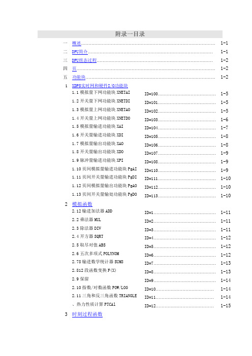
附录一目录一概述⋯⋯⋯⋯⋯⋯⋯⋯⋯⋯⋯⋯⋯⋯⋯⋯⋯⋯⋯⋯⋯⋯⋯⋯⋯⋯⋯⋯⋯⋯1-1 二DPU简介⋯⋯⋯⋯⋯⋯⋯⋯⋯⋯⋯⋯⋯⋯⋯⋯⋯⋯⋯⋯⋯⋯⋯⋯⋯⋯⋯⋯1-1 三DPU组态过程⋯⋯⋯⋯⋯⋯⋯⋯⋯⋯⋯⋯⋯⋯⋯⋯⋯⋯⋯⋯⋯⋯⋯⋯⋯⋯1-2 四页⋯⋯⋯⋯⋯⋯⋯⋯⋯⋯⋯⋯⋯⋯⋯⋯⋯⋯⋯⋯⋯⋯⋯⋯⋯⋯⋯⋯⋯⋯⋯1-2 五功能块⋯⋯⋯⋯⋯⋯⋯⋯⋯⋯⋯⋯⋯⋯⋯⋯⋯⋯⋯⋯⋯⋯⋯⋯⋯⋯⋯⋯⋯1-2 1 XDPS实时网和硬件I/O功能块1.1模拟量下网功能块XNETAI ID=100⋯⋯⋯⋯⋯⋯⋯⋯⋯⋯⋯⋯⋯1-51.2开关量下网功能块XNETDI ID=101⋯⋯⋯⋯⋯⋯⋯⋯⋯⋯⋯⋯⋯1-51.3模拟量上网功能块XNETAO ID=102⋯⋯⋯⋯⋯⋯⋯⋯⋯⋯⋯⋯⋯1-51.4开关量上网功能块XNETDO ID=103⋯⋯⋯⋯⋯⋯⋯⋯⋯⋯⋯⋯⋯1-61.5模拟量输进功能块XAI ID=104⋯⋯⋯⋯⋯⋯⋯⋯⋯⋯⋯⋯⋯1-71.6开关量输进功能块XDI ID=105⋯⋯⋯⋯⋯⋯⋯⋯⋯⋯⋯⋯⋯1-81.7模拟量输出功能块XAO ID=106⋯⋯⋯⋯⋯⋯⋯⋯⋯⋯⋯⋯⋯1-81.8开关量输出功能块XDO ID=107⋯⋯⋯⋯⋯⋯⋯⋯⋯⋯⋯⋯⋯1-91.9脉冲量输进功能块XPI ID=108⋯⋯⋯⋯⋯⋯⋯⋯⋯⋯⋯⋯⋯1-91.10页间模拟量输进功能块PgAI ID=110⋯⋯⋯⋯⋯⋯⋯⋯⋯⋯⋯⋯⋯1-91.11页间开关量输进功能块PgDI ID=111⋯⋯⋯⋯⋯⋯⋯⋯⋯⋯⋯⋯⋯1-101.12页间模拟量输出功能块PgAO ID=112⋯⋯⋯⋯⋯⋯⋯⋯⋯⋯⋯⋯⋯1-101.13页间开关量输处功能块PgDO ID=113⋯⋯⋯⋯⋯⋯⋯⋯⋯⋯⋯⋯⋯1-102 模拟函数2.12输进加法器ADD ID=1⋯⋯⋯⋯⋯⋯⋯⋯⋯⋯⋯⋯⋯⋯1-112.2乘法器MUL ID=2⋯⋯⋯⋯⋯⋯⋯⋯⋯⋯⋯⋯⋯⋯1-112.3除法器DIV ID=3⋯⋯⋯⋯⋯⋯⋯⋯⋯⋯⋯⋯⋯⋯1-112.4开方器SQRT ID=4⋯⋯⋯⋯⋯⋯⋯⋯⋯⋯⋯⋯⋯⋯1-122.5取尽对值ABS ID=5⋯⋯⋯⋯⋯⋯⋯⋯⋯⋯⋯⋯⋯⋯1-122.6五次多项式POLYNOM ID=6⋯⋯⋯⋯⋯⋯⋯⋯⋯⋯⋯⋯⋯⋯1-122.78输进数学统计器SUM8 ID=7⋯⋯⋯⋯⋯⋯⋯⋯⋯⋯⋯⋯⋯⋯1-132.812段函数变换F(X) ID=8⋯⋯⋯⋯⋯⋯⋯⋯⋯⋯⋯⋯⋯⋯1-132.9保留ID=9⋯⋯⋯⋯⋯⋯⋯⋯⋯⋯⋯⋯⋯⋯1-142.10指数/对数函数POW/LOG ID=10⋯⋯⋯⋯⋯⋯⋯⋯⋯⋯⋯⋯⋯1-142.11三角和反三角函数TRIANGLE ID=11⋯⋯⋯⋯⋯⋯⋯⋯⋯⋯⋯⋯⋯1-14、热力性质计算PTCAl ID=12⋯⋯⋯⋯⋯⋯⋯⋯⋯⋯⋯⋯⋯1-15 3 时刻过程函数超前滞后模块LEADLAG ID=20⋯⋯⋯⋯⋯⋯⋯⋯⋯⋯⋯⋯⋯1-16 滞后模块DELAY ID=21⋯⋯⋯⋯⋯⋯⋯⋯⋯⋯⋯⋯⋯1-16 微分模块DIFF ID=22⋯⋯⋯⋯⋯⋯⋯⋯⋯⋯⋯⋯⋯1-17 时域统计模块TSUM ID=23⋯⋯⋯⋯⋯⋯⋯⋯⋯⋯⋯⋯⋯1-17 数字滤波FILTER ID=24⋯⋯⋯⋯⋯⋯⋯⋯⋯⋯⋯⋯⋯1-18 歪坡信号发生器ID=25⋯⋯⋯⋯⋯⋯⋯⋯⋯⋯⋯⋯⋯1-18 段信号发生器f(t) ID=26⋯⋯⋯⋯⋯⋯⋯⋯⋯⋯⋯⋯⋯1-18 伪随机信号发生器Undefined ID=27⋯⋯⋯⋯⋯⋯⋯⋯⋯⋯⋯⋯⋯1-19 时域开关量统计模块TSUMD ID=28⋯⋯⋯⋯⋯⋯⋯⋯⋯⋯⋯⋯⋯1-19 4 操纵用算法二选一选择器TWOSEL ID=30⋯⋯⋯⋯⋯⋯⋯⋯⋯⋯⋯⋯⋯1-20 三选一选择器THREESEL ID=31⋯⋯⋯⋯⋯⋯⋯⋯⋯⋯⋯⋯⋯1-20 无扰切换模块SFT ID=32⋯⋯⋯⋯⋯⋯⋯⋯⋯⋯⋯⋯⋯1-21 上下限幅器HLLMT ID=33⋯⋯⋯⋯⋯⋯⋯⋯⋯⋯⋯⋯⋯1-21 上下限报警HLALM ID=34⋯⋯⋯⋯⋯⋯⋯⋯⋯⋯⋯⋯⋯1-21 速率限制器RATLMT ID=35⋯⋯⋯⋯⋯⋯⋯⋯⋯⋯⋯⋯⋯1-22 速率报警器RATALM ID=36⋯⋯⋯⋯⋯⋯⋯⋯⋯⋯⋯⋯⋯1-22 偏差运算DEV ID=37⋯⋯⋯⋯⋯⋯⋯⋯⋯⋯⋯⋯⋯1-23 PID运算EPID ID=38⋯⋯⋯⋯⋯⋯⋯⋯⋯⋯⋯⋯⋯1-24 简单PID模块Undefined ID=39⋯⋯⋯⋯⋯⋯⋯⋯⋯⋯⋯⋯⋯1-24 2输出平衡模块Balance2 ID=40⋯⋯⋯⋯⋯⋯⋯⋯⋯⋯⋯⋯⋯1-25 八输进平衡模块BALANCE8 ID=41⋯⋯⋯⋯⋯⋯⋯⋯⋯⋯⋯⋯⋯1-26 数字驱动伺服模块DDS ID=42⋯⋯⋯⋯⋯⋯⋯⋯⋯⋯⋯⋯⋯1-26 查表式模糊操纵器FTAB ID=43⋯⋯⋯⋯⋯⋯⋯⋯⋯⋯⋯⋯⋯1-27 5慢信号保卫模块SAIPro ID=44⋯⋯⋯⋯⋯⋯⋯⋯⋯⋯⋯⋯⋯1-28 5 逻辑电路2输进与AND ID=50⋯⋯⋯⋯⋯⋯⋯⋯⋯⋯⋯⋯⋯1-29 2输进或OR ID=51⋯⋯⋯⋯⋯⋯⋯⋯⋯⋯⋯⋯⋯1-29 反相器NOT ID=52⋯⋯⋯⋯⋯⋯⋯⋯⋯⋯⋯⋯⋯1-29 异或器XOR ID=53⋯⋯⋯⋯⋯⋯⋯⋯⋯⋯⋯⋯⋯1-30 8输进数量或QOR8 ID=54⋯⋯⋯⋯⋯⋯⋯⋯⋯⋯⋯⋯⋯1-30 RS触发器ID=55⋯⋯⋯⋯⋯⋯⋯⋯⋯⋯⋯⋯⋯1-30 定时器TIMER ID=56⋯⋯⋯⋯⋯⋯⋯⋯⋯⋯⋯⋯⋯1-31 计数器CNT ID=57⋯⋯⋯⋯⋯⋯⋯⋯⋯⋯⋯⋯⋯1-32模拟对比器CMP ID=58⋯⋯⋯⋯⋯⋯⋯⋯⋯⋯⋯⋯⋯1-33循环定时器CYCTIMER ID=59⋯⋯⋯⋯⋯⋯⋯⋯⋯⋯⋯⋯⋯1-33步序操纵器STEP ID=60⋯⋯⋯⋯⋯⋯⋯⋯⋯⋯⋯⋯⋯1-34软件脉冲列输出SPO ID=61⋯⋯⋯⋯⋯⋯⋯⋯⋯⋯⋯⋯⋯1-356 操作器模拟软手操器S/MA ID=70⋯⋯⋯⋯⋯⋯⋯⋯⋯⋯⋯⋯⋯1-36键盘模拟量增减KBML ID=71⋯⋯⋯⋯⋯⋯⋯⋯⋯⋯⋯⋯⋯1-37数字手操器DEVICE ID=72⋯⋯⋯⋯⋯⋯⋯⋯⋯⋯⋯⋯⋯1-37简单数字手操器D/MA ID=73⋯⋯⋯⋯⋯⋯⋯⋯⋯⋯⋯⋯⋯1-41带开关输出的模拟软手操器ADS/MA ID=74⋯⋯⋯⋯⋯⋯⋯⋯1-416.6电气数字手操器EDEVICE ID=75⋯⋯⋯⋯⋯⋯⋯⋯⋯⋯⋯⋯⋯1-427 特殊功能块品质(状态)测试模块ID=80⋯⋯⋯⋯⋯⋯⋯⋯⋯⋯⋯⋯⋯1-44触发执行事件EVENT ID=81⋯⋯⋯⋯⋯⋯⋯⋯⋯⋯⋯⋯⋯1-4416个布尔变量转换为长整形变量B16TOL ID=82⋯⋯⋯⋯⋯⋯⋯⋯1-45长整形变量转换为16位布尔个变量LTOB16 ID=83⋯⋯⋯⋯⋯⋯⋯⋯1-45长整型模拟变量含义转换器LTOF ID=84⋯⋯⋯⋯⋯⋯⋯⋯1-45节点(状态)测试模块TDPU ID=85⋯⋯⋯⋯⋯⋯⋯⋯⋯⋯⋯⋯⋯1-46上网报警闭锁功能块DisAlm ID=86⋯⋯⋯⋯⋯⋯⋯⋯⋯⋯⋯⋯⋯1-46上网报警限修改功能块ChgAlm ID=87⋯⋯⋯⋯⋯⋯⋯⋯1-46I/O卡件测试模块TCard ID=88⋯⋯⋯⋯⋯⋯⋯⋯⋯⋯⋯⋯⋯1-477.10I/O站测试模块TNode ID=89⋯⋯⋯⋯⋯⋯⋯⋯⋯⋯⋯⋯⋯1-47 附录一XDPS预定义标准功能块讲明一、概述XDPS的软件功能分DPU和MMI,MMI又包括OPU、ENG、HSU等,DPU又有VDPU、专用GTW 等。
SPX双作用液压阀门产品说明书
®
SPX Hydraulic Technologies 5885 11th Street Rockford, IL 61109-3699 USA
Tech. Services: (800) 477-8326 Fax: (800) 765-8326
Order Entry: (800) 541-1418 Fax: (800) 288-7031
Fax: (800) 283-8665 International Sales: (507) 455-7223
Fax: (507) 455-7746
Form No. 100303
Parts List for:
51684 RD1506 RD15013
DOUBLE-ACTING
HYDRAULIC CYLINDER
Max. Capacity: 153.4 Tons at 10,000 PSI
Double-acting Cylinder
Relief Valve
See important
DANGER
statement on back of sheet 1 of 1
© SPX Corporation
Sheet No. 1 of 1
to Piston Rod [Item #9]. Torque to 200 ft. lbs.)
T-Seal & Backup Rings (Smooth side of Backup Ring must be
against seal.)
Cylinder Body (For RD1506) Cylinder Body (RD15013 & 51684) 45° Elbow Fitting (For 51684) Quick Coupler Ram Half w/Dust Cap
Sartorius XQ 6100 6100 B电子搅拌计量秤使用及操作指南说明书
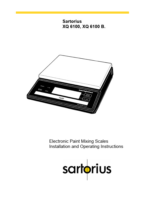
SartoriusXQ 6100, XQ 6100 B.Electronic Paint Mixing ScalesInstallation and Operating InstructionsSartoriusXQ 6100, XQ 6100 B.Please read these installation and operating instructions care-fully before operating your new scale.With this Sartorius Scale you have acquired a sophisticated,user-friendly electronic precision weighing instrument whichwill enable you to consistently match any colour to meet yourpaint supplier's high quality Standards.When operating this scale, please observe a few simple basicrules.Should you have additional questions after familiarizing yourpaint with this manual, please contact your paint supplier.2Contents.PageEquipment Supplied 5Installation Instructions 6Startup 7 Operation 8 Examples for Paint Mixing 9Calibration 15 Accessories (Options) 17Spezifications 1734 1 Weighing pan 2 Power receptacle3 Weight and linear range display4 TINTER/ADDITIVE key5 Set 100% key6 Access switch (for calibration)7 Tare control 8 PRINT key (functions only if the scalehas a built-in interface)9 RECALL WEIGHT-Taste 10ON/OFF key11 %/g key 12Manufacturer’s label (on the bottom of thebase plate of the scale)5Equipment Supplied. Do not miss out on the benefits of our warranty. Please fill out the warranty card, indicating the date of installa-tion, and return the card to your Sartorius dealer. Carefully unpack the scale and the accessory components. Save all packing material for future use. The equipment supplied comprises the components shown on the left: - Scale - Dust cover - AG adapter - Weighing pan lf you wish to send in your scale for repair work, please pro-ceed as follows: - remove all splashes or spills of paint - include a description of the equipment failures/faults. This will save you time and unnecessary expense for servic-ing. Please replace the cardboard between the scale base and the weighing pan (1) to prevent damage to the weighing system during shipment.6 Installation Instructions.Your Sartorius Scale provides exact readouts even under less than ideal conditions.However, exposure to extreme heat, vibrations or drafts may adversely affect the weighing accuracy and should be avoided whenever possible.The scale can be adapted to your particular requirements and to the specific ambient conditions simply by changing the menu code settings in the scale operating program. Please contact your dealer for assistance.After you have plugged your scale into the AC adapter and turned it on, allow for at least 30 minutes warmup. Once the scale has been warmed up, the STANDBY feature will enable you to skip the warmup procedure.Important NoteMake sure to unplug the AC adapter from the wall outlet be-fore you connect or disconnect additional devices (printer or PC) to or from the interface connector (Option). Startup.Remove the white backing from the adhesive disks on the dust cover. Attach the dust cover to the scale base by slightly pressing down on the adhesive disks.Mount the weighing pan (1) on the scale.Double-check to be sure that the base dust cover does not come in contact with the weighing pan.Your scale is powered by an AC adapter. Check that the volt-age rating printed on this unit is identical to your local line voltage.Plug the line cord of the adapter into the power receptacle of the scale. Now plug the AC adapter into an electrical or wall outlet.Whenever possible, avoid connecting your scale to over-loaded networks (compressors or similar equipment).lf you have problems with your local line power supply, use a suitable voltage stabilizer or an emergency power supply unit (Option). Be sure to contact your dealer for technical informa-tion.7Operation.Press the ON/OFF key (10) to turn the scale on or off. The display will go out whenever you turn off the scale. All other circuits will remain energized (STAND-BY state). This means the scale is immediately ready to operate without re-quiring warmup the next time you switch it on. Important Note To use the STANDBY feature, the scale must have been plugged into the AC adapter for at least 30 minutes (initial warmup). After the scale is turned on, an automatic self-test of the scale's electronic circuitry is performed. This self-test ends with the readout 0.0 g. Any other readout indicates an error. In this case, please con-tact your dealer, describing exactly what the display reads8 lf you wish to use a Container or if the weight display does not indicate 0.00 g (or the equivalent with the weight unit of your choice), press the tare control to zero the display.Important NoteThe small circle in the lower left-hand corner shows that the scale has been exactly tared so the display reads "0."Do not wait to replace worn dust covers.Make sure that paint spills over the sides of the housing do not harden, making the pan stick to the base. Frequent cleaning with solvents (such as paint thinner) will warp the dust cover which may then push against the pan, causing the readout to drift.9Examples for Paint Mixing. 1st Example Mix paint components with hardener (35% of the total weight of the paint quantity) and 20% thinner. The 20% thinner is in proportion to the total weight of the paint components and hardener. ——————————————————————————— Place an empty container on the scale and tare ——————————————————————————— Weigh in the 1st paint component according to your formula and then store it - press the key (4) ——————————————————————————— weigh in the 2nd paint component according to your formula and then store it - press the key (4)———————————————————————————10 You can obtain a display of the total net weight of the paint components by pressing thekey (9)——————————————————————————— To store the total net weight as 100 % –press the key (5)The decimal place will automatically disappear once the total weight is stored as 100 % or "E" will be displayed if the paint components are too light for the particular shade of paint. If "E" is displayed, press the RECALL WEIGHT key and in-crease the minimum amount of the individual paint components. ——————————————————————————— Add 35% hardener——————————————————————————— To display the momentary weight(paint components + hardener) –press the key (11)——————————————————————————— To store the total weight-press the key (9)———————————————————————————11Again, to store the total weight as 100 % – press the key (5) ——————————————————————————— Add 20% thinner Important Note: Make sure that the 20% thinner is in proportion to the total weight of the paint components and to the hardener. ——————————————————————————— to display the update total weight (paint components + hardener + thinner) – press the key (11) ——————————————————————————— The key (9) deletes the stored factor for calculation the percentages..12 2nd ExampleMix paint components with 13.5% hardener and 6.5% thinner. These percentages are in proportion to the total weight of the paint quantity(1st paint component + 2nd component = 100%).——————————————————————————— ^Place empty container on the scale and tare.——————————————————————————— To weigh in the paint components according to your for-mula and store them, see "1st Example" on page 9. ——————————————————————————— Display the total net weight of the paint components by press-ing thekey (9)———————————————————————————13To store the total net weight as 100 % - press the key (5) The decimal place will automatically disappear once the total weight is stored as 100 % or "E" will be displayed if the paint components are too light for the particular shade of paint. lf "E" is displayed, press the RECALL WEIGHT key and in-crease the minimum amount of the individual paint components.. ——————————————————————————— To store the amount as 100% – press the - key (4) ——————————————————————————— Add 13.5% hardener ———————————————————————————14 To add and store the updated total weight,press the key (4)——————————————————————————— Add 6,5% thinner——————————————————————————— Display the total net weight in percent by pressing thekey (9)——————————————————————————— To display the total net weight in the particular weight unit se-lected (in this case “g”) –press the key (11) ——————————————————————————— The key (9) deletes the stored factor for calculating the percentages.15Calibration.Have your scale checked and recalibrated, if necessary, by your dealer on the basis of a regular maintenance schedule. lf you have an accurate calibration weight (5,000 g ± 0.03 g; see Sartorius "Accessories" on page 17), proceed as follows: Remove the protective cap located on the front right of your scale and slide the access switch (6) in the direction of the ar-row. Turn off the scale, hold down the TINTER/ADDITIVE key (4) and briefly press the ON/OFF key (10). Upon the completion of the self-test release TINTER/ADDITIVE key when "C" is displayed. Unload the scale and tare. Press the TINTER/ADDITIVE key (4) when the display reads zero. "CAL" and the calibration weight readout will now be displayed.Centre the calibration weight on the weighing pan. Array Now the weight unit symbol is displayed. lt indicates the endof the calibration procedure.Relock the calibration access function by sliding the accessswitch back to its original setting, and replace the protectivecap.After calibration, use the ON/OFF key (10) to turn the scale offand then on again.Even if you do not calibrate your scale, this will not affect theaccuracy of the mixing ratio so you will always obtain the cor-rect shade of paint, provided you weigh in the componentscorrectly.However, the overall amount of your paint formula may slightlyvary.16Accessories (Options).Dust cover 69 60Q610Calibration weight (1 x 5000 g) 7072 13Antitheft locking device 6087For information on additional accessories, please contact yourdealer.Options:InterfaceExternal rechargeable batteryPrinterVoltage stabilizerEmergency power supply unitSpecifications.Model XQ 6100 XQ 6100 BCapacity g61006100 Readability g0,10,1 Tare range (by subtraction) g 6100 6100Standard deviation g ≤± 0,05 ≤± 0,5Max. linearity g ≤± 0,1 ≤± 0,5Stabilization (typical) s 1,5Display update— at stability (depends on the filter level selected— when load is changed ss0,1; 0,2; 0,40,1Adaptation to operating requirementand ambient conditions by selecting one of 3 optimised filter levelStability range d 0,25 ... 32 (selectable)Ambient temperature range K 273 — 313 (0o C .. +40o C)Allowable relative humidity % 15 ... 85 (moisture-proof rating; non-condensing) Sensitivity driftwithin 10 ... 30o C /o C ≤± 5 ∙ 10-6≤± 2,5 ∙ 10-5Pan size mm 235 x 180Scale base (W x D x H) mm 250 x 270 x 65Net weight, approx. kg 4 3,5Line voltage,(mains); frequency: 50-60 Hz115 or 230 V, depending on the AC adapter used Allowable voltage fluctuation -20% (15)Power consumption VA 7,5 (typical)Wattage rating of the scale for an inputvoltage of 12 Vw 0,55 0,3617Sartorius AGB37070 GöttingenP Weender Landstraße 94–108, 37075 GöttingenT (0551) 308-0,F(0551) 308-3289Internet: Copyright by Sartorius AG, Göttingen, Deutschland.All rights reserved. No part of this publication may beprinted or translated in any form or by any means withoutthe prior written permission of Sartorius AG.Sartorius AG reserves the right to make change to the technology, features, specification and design of the equipment without notice.。
SPX Corporation 单动、弹簧返回的水力杠机说明书
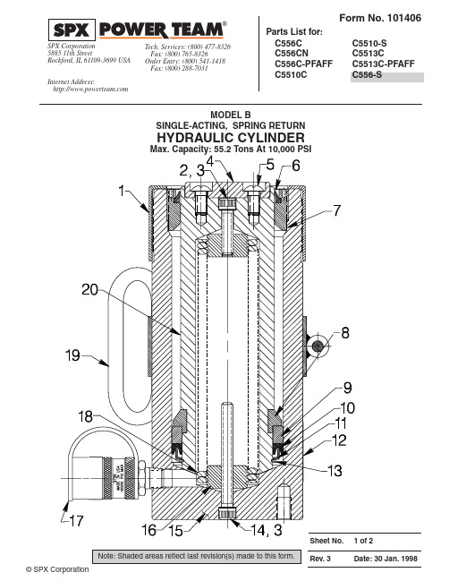
Part numbers marked with an asterisk (*) are contained in Standard Repair Kit No. 300114.Part numbers marked with a dagger (†) are contained in Viton Seal Kit No. 300215.1421931Thread Protector2109841Cap Screw (3/8-16 UNC x 1-1/2 Lg.;Torque to 500/550 in. lbs.For C556C, C556CN, C5510C,C556C-PFAFF & C556-S)161101Cap Screw (3/8-16 UNC X 3-1/2 Lg.;Torque to 500/550 in. lbs.For C5513C, C5513C-PFAFF , &C5510-S)3†*120422Copper Washer (9/16 X 3/8 X 1/32)4361611Ram Saddle (All except C5510-S &C556-S)5161122Machine Screw (3/8-16 UNC X 3/4 Lg.; Tighten securely)6*161171Rod Wiper †2057181Rod Wiper 7361381Retainer Nut(Torque to 125/150 in. lbs.)8360011Keeper Ring 92014811Piston Head 10*159161U-cup †2057061U-cup112014801Slip Retainer123509591Trade Name Decal (For C556C)3509671Trade Name Decal (For C5510C)3509681Trade Name Decal (For C5513C)3512441Trade Name Decal (For C556CN)2521841Trade Name Decal (ForC556C-PFAFF & C5513C-PFAFF)13*161181Retaining Ring14161101Cap Screw (3/8-16 UNC X 3-1/2 Lg.;Torque to 500/550 in. lbs.)15646551Cylinder Body (For C556C & C556C-PFAFF)646571Cylinder Body (For C5510C &C5510-S)646591Cylinder Body (For C5513C &C5513C-PFAFF)651621Cylinder Body (For C556CN &C556-S)16361702Spring Retainer (See detail on sheet2 of 2)1797961Ram Half Coupler w/ Dust Cap(For all except C5510-S & C556-S)182014831Extension Spring (For C556C,C556CN, C556C-PFAFF & C556-S)2502631Extension Spring (For C5510C &C5510-S)2014841Extension Spring (For C5513C &C5513C-PFAFF)19420396OR91Cylinder Lift Handle Assembly(For all except C5510-S & C556-S)20508371Piston Rod (For C556C, C556CN &C556C-PFAFF , C556-S)580541Piston Rod (For C5510C & C5510-S)508361Piston Rod (For C5513C & C5513C-PFAFF)PARTS INCLUDED BUT NOT SHOWN 2039081Warning Decal (For C556C, C556CN, C556-S)*377821Warning Decal (For C5510C,C5510-S, & C5513C)203908-CE 1Warning Decal (For C556C-PFAFF)37782-CE 1Warning Decal (For C5513C-PFAFF)†2065571U-cup Backup Washer†195261O-ring (1" x 3/4 x 1/8; For coupler)†2057241Decal (Viton seals)111271Plug Fitting (For C5510-S & C556-S)2021731Trade Name Decal (For C5510-S &C556-S)SPRING & RETAINER ASSEMBLY.200.220Refer to any operating instructions included with this product for detailed information about operation, testing, disassembly, reassembly, and preventive maintenance.Items found in this parts list have been carefully tested and selected. Therefore: Use only genuine Power Team replacement parts!Additional questions can be directed to our Technical Services Department.Parts List, Form No. 101406, Back sheet 2 of 2TILT SADDLE CAP ASSEMBLY(FOR C5510-S & C556-S)(1/4-20 X 1" Lg.)33502521Swivel Cap43502541Tilt Saddle BaseASSEMBLY INSTRUCTIONS1.Mount tilt saddle base to cylinder piston with appropriate socket head cap screws (Item 1). Torque as specified.2.Position swivel cap on base and tilt until lip on swivel cap contacts the base.3.Thread in self-locking flat head screw. DO NOT overtighten. Swivel cap should swivel freely, and lip on swivel capshould always contact the base at maximum tilt angle. The lip is not intended to support the load, only to indicate the maximum tilt angle.。
xsch使用说明书
XSCH仪表使用说明书目录1、概述 (1)2、型号规格 (2)3、技术规格 (3)4、安装与接线 (5)5、参数一览表 (11)6、操作 (13)6.1 面板及按键说明 (13)6.2 参数设置说明 (14)6.3 报警设定值的设置方法 (15)6.4 密码设置方法 (15)6.5 其它参数的设置方法 (16)7、功能及相应参数说明 (17)7.1 测量及显示 (17)7.2 报警输出 (19)7.3 变送输出 (20)8、调校 (21)9、抗干扰措施 (23)调校1、概述XSCH 系列数显仪与各类模拟量输出的传感器、变送器配合,完成温度、压力、流量、液位、成分等物理量的测量、变换、显示和控制。
XSCH 系列是经济型仪表,适合对精度、功能要求不高的场合,对更高的精度或功能要求,可选用XST 系列或XSE 系列。
误差小于0.5%F .S ,并具备调校、数字滤波功能,可帮助减小传感器、变送器的误差,有效提高系统的测量、控制精度适用于电压、电流、热电阻、热电偶等信号类型2点报警输出,上限报警或下限报警方式可选择。
报警灵敏度独立设定变送输出可将测量、变换后的显示值以标准电流、电压形式输出供其它设备使用 2、型号规格安装与接线3、技术规格电源:220V AC供电的仪表:220V±10%,功耗小于7V A;24V DC供电的仪表:24V±10%,功耗小于5V A;12V DC供电的仪表:9V~20V,功耗小于5V A.H工作环境:0℃~50℃,湿度低于90%R显示范围:-1999~9999,小数点位置可设定输入信号类型:电压、电流、热电阻、热电偶电压:1V~5V DC,0V~5V DC 可通过设定选择电流:4mA~20mA,0mA~10mA,0mA~20mA可通过设定选择热电阻:Pt100,Cu100,Cu50,BA1,BA2,G53可通过设定选择热电偶:K,S,R,B,N,E,J,T可通过设定选择.S基本误差:小于±0.5%F测量分辨力:1/16000,14位A/D转换器测量控制周期:0.3秒报警输出:2点继电器输出,触点容量220V AC,3A变送输出光电隔离4mA~20mA,0mA~10mA,0mA~20mA直流电流输出,通过设定选择。
Husqvarna 250X 电锡剪刀说明书
2006-28,5242011-00 TS250XTS250X SSSpare parts Pieces de rechange Piezas de repuesto5422011-00PART NO.POS.DESCRIPTION PART NO.POS.DESCRIPTION501 96 53-01A,A1,A2Blade Guard 10" - PC H. Orange542 16 78-70*D Screw, SH Shoulder, 1/2"OD x .50, 3/8"-16 504 04 02-01A,A1,A2Decal: Husq Crown H, 25mm 542 16 93-65*A,A1,A2Guard, Splash539 30 00-74I Set Collar, 1/2" ID542 16 93-66*A,A1,A2Screw, Self-Tap Pan Hd, #8 x 3/8 "B" ZP 539 30 01-23C Set Collar, 1" I.D.542 16 94-86*A,A1,A2Knob, 5/16"-18 x 1 4-Prong539 99 02-09D Screw, Hex Hd 5/16"-18 x 1"542 16 95-22*A,A1,A2Flange, Inner539 99 05-80B Screw, Hex Hd 1/4"-20 x 3/4"542 16 95-23*A,A1,A2Flange, Outer539 99 06-55C Bolt, 3/8"-16 x 1-1/2 ZP542 16 95-41A2Motor: 1HP 1425RPM 240/50/1541 20 05-60A2V-Belt, 3VX300542 16 95-63*E Water Tube Assy: 1/4"Y x 32"541 20 06-49I Set Collar, 5/8" ID542 16 95-64*E Water Tube Assy: 1/4"Y x 72"541 20 15-69A1V-Belt, 3VX280542 16 95-65*E Tube, Clear Vinyl 1/4" ID x 6"541 20 46-69A,A1,A2Washer, Spring Wave .531 ID ZP542 17 10-65*G Cutting Accessories Package541 20 48-00E Fitting, 1/4”NPT x 1/4“ Hose542 17 21-01*A Pulley 6GJ2.80 - .626 w/SS542 00 06-05A1Mtr: 1.5HP 3450 115/208-230/60/1542 17 88-25*A,A1,A2Flange Bolt, 5/16"-18 x 1 Gr5 ZP542 00 07-16A1Mtr: 2.0HP 3450 115/208-230/60/1542 18 08-10*A1Switch Box Assy w/ Wiring542 02 00-11*G Carriage Bolt, 1/4"-20 x .625 ZP542 18 70-43*A,A1,A2Decal: Warning542 02 00-60*A,A1,A2Key, .1875 Sq x 1542 18 91-15*B Capscrew, Hex Hd, 1/4"-20 x 5/8", 316SS 542 02 01-27*A,A1,A2Carriage Bolt, 5/16"-18 x 3, GR5 ZP542 18 91-16*B Locknut, Fiber 1/4"-20, 316SS542 02 01-95*A,A1,A2,B Locknut, Fiber 1/4"-20 ZP542 18 92-47*A,A1,A2Decal: Water Pump Outlet542 02 01-97*A,A1,A2,C Locknut, Fiber 5/16"-18 ZP542 18 96-60*A,A1,A2Flange Bolt, 1/4"-20 x 1/2" Gr5 ZP542 02 02-01*I Locknut, Fiber 1/2"-13542 18 96-61*A,A1,A2Cap, Bearing542 02 02-45*A,A1,A2Locknut, Wing 5/16"-18 ZP542 18 97-37*F,G,H T-Knob 1/4"-20 x 3/4"542 02 03-18*C Capscrew, Hex Hd, 5/16"-18 x 2.25 GR 5 ZP542 02 03-39*I Capscrew, Hex Hd 1/2"-13 x 1"542 19 07-36F Decal: HUSQVARNA, 4" Domed542 02 03-70*A1Capscrew, Hex Hd, 1/4"-20 x .75 GR 5 ZP542 19 07-41B Decal: Husq Target TA TS250X542 02 04-41*A,A1,A2Capscrew, Hex Hd, 5/16"-18 x 1.75 GR 5 ZP542 19 37-94*C Decal: Drain Plug542 02 04-89*C Screw, Self-Tap Hex WH, 1/4"-20 x .75 "F"542 19 38-30*A,A1,A2Flange Bolt, 1/4"-20 x 3/4" Gr5 ZP542 02 05-40*A1Set Screw, Soc Hd, 1/4"-20 x 1/4" Cup542 19 38-33*A,A1,A2Shaft, Blade542 02 05-41*A,A1Set Screw, Soc Hd, 1/4"-20 x 3/8 Cup542 19 38-66B Pan, Tile Saw, Galv542 02 05-41*A Set Screw, Soc Hd, 1/4"-20 x 3/8 Cup542 19 38-70A,A1,A2Adjustment Cam, ZP542 02 05-50*A1,A2Screw, Socket Hd, 5/16"-18 x 3/8542 19 39-16D Extension, Cart542 02 06-43*C Pin, Roll 1/4" x 1.25542 19 39-19A,A1Pin, Roll .156 x 1.00542 02 07-39*A,A1,A2Washer, Flat #10 (3/16") ZP542 19 39-20A,A1Bolt, Blade Latch, ZP542 02 07-41*A1Washer, Flat 1/4" ZP542 19 39-37D Cart w/ V-Top542 02 07-42*A,A1,A2,C,D Washer, Flat 5/16” ZP542 19 39-40D Roller, Cart Stabilizer542 02 07-62*B,C Washer, Flat SAE 1/4" ZP542 19 39-41C Spring, Torsion542 02 07-63*A,A1,A2,D Washer, Flat SAE 5/16" ZP542 19 39-44C Anchor, Spring542 02 07-66*A,A1Washer, Flat SAE 1/2” ZP542 19 39-46C Lock Bar, ZP542 02 07-85*A,A1,A2Lockwasher, Split 5/16" (M8)542 19 39-48B Rail Support542 02 07-86*C Lockwasher, Split 3/8"542 19 39-49B Rail, Tile Saw, Galv542 02 14-16*D Capscrew, Hex Hd, 5/16"-18 x 1" GR 5 ZP542 19 39-51D Cart Stop542 03 03-86*B Drain Plug Assy542 20 30-02B Pan, Tile Saw - TS 250X SS542 03 08-22*D Wheel, Cart542 20 30-11A,A1Torsion Spring, ZP542 03 09-06*A1Pulley 2G3V2.25 - .875 w/ SS542 20 30-37D Extension Assy, Cart (Optional)542 03 23-66*D Nut, KEPS 5/16"-18 ZP542 20 30-51A1Pulley 2G3V2.0 - .625 w/ SS542 04 01-26*I Wheel, 6.0" OD x .625" B542 20 30-52B Rail, Tile Saw SS542 04 63-26*A,A1,A2Decal, 3-Wire Grounded Plug542 20 30-56D Conveyor Cart Assy542 04 63-27*A,A1,A2Decal, Cord Usages542 20 30-60A Pulley 6GJ1.75 - .626 w/ SS542 05 01-03*H Knob, Adjustment542 20 30-62I Wheel, 4.0" OD x .503" B542 05 01-05*H Stop, Friction542 20 30-74I Axle, 1/2"OD x 14.4"542 05 01-06*H Spring542 20 30-83F Rip Guide Assy542 05 01-07*H Bolt, Locking - B/O542 20 31-19D Wheel, Eccentric, Yellow Zinc542 05 02-16*E Water Pump & Valve, 230V/50-60542 20 31-22I Pin, Clevis 3/8" x 2.50"542 05 02-18*E Water Pump & Valve,115V/60542 20 31-80A,A1Pad, Resilient, Self Adhesive542 05 10-10*G Protractor Assy, Adj 90 Deg542 20 31-81A,A1Blade Shaft Stop, ZP542 05 10-20*G Guide Assy, Dual 45 Deg542 20 31-93A V-Belt, Poly, 280J6542 05 10-30*G Bullnose Guide Assy, 45 Deg542 20 32-18A,A1,A2Nut, Flange, 5/16"-18 Tensilock542 05 10-61*C Pan Stop ZP542 20 32-52I Stand, Tile Saw - PC H. Gray542 05 10-64*C Assy, Pan Stop542 20 32-53I Stand, Adj Rolling - H. Gray542 05 10-65*C Tab, Plastic542 20 53-85A,A1,A2Bracket, TS Belt Guard Mtg, Z/P542 05 80-02*A2Pulley 1G3V1.9 - .625 w/ SS542 20 53-87A,A1,A2Belt Guard - PC H. Orange542 05 80-52*A2Pulley 1G3V3.67 - .625 w/ SS542 20 53-91C Frame Weld, TS250X - PC H. Gray542 07 10-81*A,A1,A2Bearing, .669 BB542 20 53-92A,A1,A2Head Platform - PC H. Gray542 07 11-10*A,A1,A2Washer, Spring542 20 54-45A,A1,A2Blade Guard Assy - TS 250542 13 95-68*I Grip, Handle542 20 54-46A,A1,A2Platform w/Bladeshaft -compl TS 250542 13 95-81*I Spring, Stand542 20 54-47A Cutting Head - compl 1.5HP 115V/60542 16 10-19*E Connector, "Y" 1/4”542 20 54-48A Cutting Head - compl 1.5HP-HT 115V/60 542 16 10-21*E Nozzle, Plastic 1/4” x 1.5542 20 54-49A1Cutting Head - compl 1.5HP- 115V/230/60 542 16 10-26*E Tube, Clear Vinyl 1/4” ID x 32"542 20 54-50B Water Pan, Galv - compl TS 250X542 16 11-34*E Valve, Flow Control542 20 54-51B Water Pan, SS - compl TS 250X542 16 13-16*E Water Pump & Valve, G300 115V/60542 16 14-79*H Support Assy, 45 Deg - Blk542 16 14-80*.H Miter Guide, 45 Deg Mighty542 16 16-41*F Wrench, 15/16”, ZP542 16 17-19*E Tube, Clear Vinyl 1/4” ID x 72"542 16 17-30*A,A1,A2Bearing Cap W/ Mounting Screws542 16 32-48*A,A1,A2Strip, Rubber Sponge542 16 70-35*I Pin, Cotter HairPART NO.POS.DESCRIPTION PART NO.POS.DESCRIPTION*** Kits ***542 03 21-24*E Kit, Water Pump - G300542 04 00-49*D Kit, Cart Wheel542 05 20-04*A Kit, Blade Shaft Replacement542 16 10-49*E Kit, Water Pump - G100 / G150542 20 40-33I Kit, Wheel - Optional-- ITEMS NOT SHOWN --542 20 10-99NS OM Op Instr: TS 250X542 20 11-00NS IPL Parts List: TS 250XPARTS For542 20 30-79 Motor (S.V.)1.5HP 1725 RPM 115V/60/1542 20 30-93NS Switch, On-Off542 20 30-95NS Overload, Manual Reset Thermal542 20 30-94NS Capacitor, 50 Mfd / 240V (Run)542 20 30-96NS Capacitor, 189-227 Mfd / 125V (Start)PARTS For542 19 30-42 Motor (SF 1.15)1.5HP 1725 RPM 115V/60/1542 19 38-85NS Switch, On-Off DPST542 03 01-41*NS Switch, Dual Voltage Toggle542 00 08-73*NS Overload, Manual Reset Thermal542 16 94-94*NS Capacitor, 40 Mfd / 370V (Run)542 16 94-93*NS Capacitor, 270-324 Mfd / 125V (Start)PARTS For542 00 06-05 Motor (D.V.)1.5HP 3450 RPM 115V-230/60/1542 16 15-81*NS Switch, On-Off DPST542 03 01-41*NS Switch, Dual Voltage Toggle542 00 08-73*NS Overload, Manual Reset ThermalNone NS Capacitor, (Run)542 18 91-17*NS Capacitor, 485 Mfd / 110V (Start)PARTS For542 16 95-41 Motor (S.V.)1.0HP 1425 RPM 220V/50/1542 20 30-93NS Switch, On-Off542 16 97-50*NS Overload, Manual Reset ThermalNone NS Capacitor, (Run)542 11 00-58*NS Capacitor, 400-480 Mfd / 165V (Start)See 542 20 10-99 Operator's Manual for Wiring DiagramsReference DiagramF r o ntT o p R ig h tA,A1,A2BCFEDGHIF r o ntT o pR ig h tF r o ntT o pR ig h t*5399902-09*5421939-40(x2)*5421678-70(x2)*5420207-42*5420323-66(x4)*5420308-22(x2)*5421939-51EWater Pump &Tube Assy*Compl (Standard 115V 60Hz)5420502-18DConveyor Cart Assy and Extension*Compl 5422030-56**Compl 5422030-37(Optional Extension)**5399902-09(x2)**5420207-63(x2)**5421939-16**5420323-66(x2)*5421939-37**5412048-00*5421611-34**Compl (32”Tube Assy)5421695-635421610-195421695-65(x2)**5421610-265421610-21(x2)*Compl (Heavy Duty 115V 60Hz)5421613-16Repair Kits:5421610-49(G100Pump -5420502-18)*5422031-19(x2)Adjustable Side (Yellow Wheels)01.13.06***Compl (72”Tube Assy)5421695-64********5421617-19*Compl (Heavy Duty 230V 50Hz)5420502-165421610-49(G100Pump -5421613-16)5420502-16)*5420207-42(x2)12.06.065420300-49Wheel KitF ro ntT opR ig htF ro ntT opR ig ht01.28.05F ro ntT opR ig ht01.28.05F Tile Saw Accessories and Tools(Standard)*5422030-83Rip Guide Assy*5421897-375421616-41Tile Saw Accessory Group(Optional)*5420510-20Dual45Angle Guideo*5420510-3045Bull Nose Mitero*5420510-1090Protractoro5421616-41Wrench:15/16x9/16x1/2Compl5421614-8045o Mighty MiterGTile Saw Accessory(Optional)H5420202-445420200-115421897-375421897-37 *Compl5421710-655421614-795420501-055420501-075420501-03 5421897-37(x2)5420501-065421897-3709.13.065421907-36*5421907-36(X2)(X2)Compl5422032-53Adjustable Rolling StandCustomer Service:800-288-5040Customer Serv.Fax:800-825-0028Printed in the USAHusqvarna Construction Products N.A.Corporate Office17400West 119th StreetOlathe,Kansas 66061Tel.913-928-1000Fax 913-438-7951。
EDX3000-RoHS操作使用说明-客户培训(共12页)

EDX3000B〔Rohs〕操作使用方法一、X荧光阐发道理X射线照在样品上会对样品发生几种作用,物质特征X射线、散射、光电子、其它作用。
1、物质特征射线每个元素本身特有的能量必然的X射线〔又叫X荧光〕,是我们阐发的根底。
2、散色构成光谱的本底。
3、光电子是探测器的工作的根底。
在样品中,其主要元素含量为I1、I2、I3、I4、I5……等。
那么样品的元素含量是元素的X荧光强度I的函数。
通式如下:C=f(I1, I2, I3, I4, I5………)这个函数关系一般比较复杂,不好计算,经验公式如下:C=f(K1I1 + K2I2 + K3I3 + K4I4 + K5I5………)C为样品的含量,I1、I2、I3、I4、I5……暗示各元素的X荧光强度,K1、K2、K3、K4、K5为代定系数。
通过成立刻度尺度,测得样品含量的样品,便可以确定K1、K2、K3、K4、K5系数。
二、X荧光特点X荧光光谱仪,由于具备尝试室的阐发精度、实现了真正的便当性以及操作简易性,使其在环境庇护和金属元素阐发领域引发了新一轮技术浪潮。
※无损测试,样品无需前处置※专用的RoHS软件※简便的仪器操作方式※快速阐发三、仪器的安装及安然使用方法1、仪器的安装仪器的安装方法非常简便,①将电源线保持到电源插座,并用并口连接线和USB连接线将计算机和仪器连接起来。
②如果安装打印机,先将打印机电源线连接好,并将打印机数据线,保持到计算机相应的接口上即可。
〔如果需要安装打印机驱动程序,请按照计算机的提示安装〕2、开机,并机方法。
A、开机方法查抄电源线是否保持好,开启仪器内部的总电源开关,即可启动仪器。
再开启计算机,计算机自动进入windows操作界面。
〔本仪器如需要,可以24小时开机使用〕B、关机方法①先将仪器的测试程序退出,并关闭。
②点击windows桌面左下角,“开始〞按钮,在弹出的菜单中,选择“关机……〞项,在弹出的新对话框中选择“关闭计算机〞项,并点击“确定〞按钮,关闭windows操作系统。
- 1、下载文档前请自行甄别文档内容的完整性,平台不提供额外的编辑、内容补充、找答案等附加服务。
- 2、"仅部分预览"的文档,不可在线预览部分如存在完整性等问题,可反馈申请退款(可完整预览的文档不适用该条件!)。
- 3、如文档侵犯您的权益,请联系客服反馈,我们会尽快为您处理(人工客服工作时间:9:00-18:30)。
使用说明书本使用说明书适用于XD型高效多管除尘器+XSP型脱硫塔的两段式燃煤工业锅炉烟气治理系统。
一、设备结构说明1、XD04型高效多管除尘器本设备分为三体上箱、中箱、下箱。
1.1上箱体为集风室,净化后的锅炉烟气在上箱汇集后由出风口经烟道进入引风机。
1.2中箱体为除尘室,内置有24件旋风子,对锅炉烟气分成24个单元进行除尘净化。
1.3下箱体为烟尘收集室,旋风子除掉的烟尘汇集在灰斗内,定期通过用户单配的星型卸料阀或锁灰阀外排到灰箱或灰车外运,或排入水封冲灰器由水力冲走。
2、XSP04型脱硫塔本设备由上、中、下塔体组成,碳钢壳体,内衬铸石防腐层。
脱硫塔与脱硫循环水箱串联,水箱为碳钢壳体,内衬耐酸水泥。
2.1上塔由两层折板脱水装置、一级清水喷淋装置、一级挡水装置、出风口及检修人孔组成。
2.2中塔由一级接水装置、两级喷淋装置、及检修人孔组成。
2.3下塔由进风口、检修人孔、一级旋流装置、一级喷淋装置及检修人孔组成。
二、脱硫除尘设备技术性能参数三、工艺流程示意图四、设备工作原理XD 型高效多管除尘器+XSP 型脱硫塔是由两级除尘脱硫组成,第一级为XD 型高效多管除尘器,烟气经烟道进入XD 型高效多管除尘器,在除尘器内烟气切向进入各均匀布置的旋风子,受旋风的离心分离作用,将绝大部分颗粒较大的粉尘分离出,并进入灰斗,烟尘可同炉渣一起处理。
第二级为脱硫除尘,烟气经过XD型高效多管旋风除尘器除尘后,由引风机鼓入XSP型脱硫塔,烟气由脱硫塔下部均匀上升,穿过多级喷淋装置形成的高密度喷淋洗涤反应区,脱硫循环水通过MP型喷嘴生成极细的雾滴和烟气反应,使得气液两相进行充分地传质和传热的物理化学反应,从而达到SO2的高效脱除。
吸收SO2后的脱硫循环水往下流往钢制脱硫循环水箱。
经搅拌器调整好循环水的PH值后循环使用。
脱硫塔上部设有一级清水循环深度除尘装置,通过清水对烟气的再次洗涤,确保烟尘排放达标。
经过清水洗涤后的锅炉烟气继续在塔内上升,经过两级折板脱水装置,脱水装置对含湿烟气进行高效脱水,经过脱水的锅炉烟气由烟道进入烟囱达标排放。
脱硫循环水管路出口设PH值控制仪测点,PH值控制仪监测脱硫循环水PH值,采用人工加药方法调整后脱硫循环水循环使用。
SO2 + H2O → H2SO3MgO + H2O → Mg(OH)2H2SO3 + Mg(OH)2 → MgSO3↓+ 2H2O2MgSO3 +O2 → 2MgSO4附件:1、脱硫塔操作运行须知2、脱硫塔常见故障及维修方法3、锅炉脱硫除尘系统消耗碱量和价格参考表4、多管除尘器运行须知北京西山新干线除尘脱硫设备有限公司二OO八年九月附件一:脱硫塔操作运行须知一、系统投运前的检查1、循环水各支路阀门开度是否正常,系统各个阀门开度可根据实际运行情况进行局部调整。
2、脱硫、清水循环泵工作是否正常:循环泵运行操作详见《使用说明书》。
3、循环水到达脱硫塔喷淋装置的水压要在0.2~0.25MPa左右,可以通过阀门开度控制各供水支管路内水压的大小。
4、脱硫塔脱硫循环水箱是否形成液封,以防运行中形成的液位差大于水封高度,导致系统漏风,循环水被烟气大量携带进入烟道。
5、引风机工作是否正常:引风机运行操作详见《使用说明书》。
6、加药是否正常。
6.1 MgO粉应根据循环水PH值的高低,连续均匀的加入脱硫循环水箱。
6.2 脱硫循环水箱内的搅拌器禁止空转、间歇运行和超载运行。
6.3 加药用循环水可用脱硫除尘系统的循环水、清水喷淋循环水,也可用自来水。
当使用自来水加药时,这部分水可作为脱硫除尘系统的循环水的补水。
6.4脱硫循环水箱出口安装管式过滤器,加药后定期排污。
二、投运操作说明1、应先启动脱硫、清水循环水泵,开启循环水供水总阀门,调整阀门开度,使脱硫塔水封良好,再启动引风机。
2、锅炉运行稳定、正常,鼓、引风机系统工作正常,此时排烟温度(进除尘系统前)一般在130~160℃,炉膛负压一般在0~-20Pa。
3、脱硫除尘器出口烟温一般在45℃左右,超过50℃时要检查循环水各支管的供水压力是否达到要求值(即供水量是否充足),水量有否变化。
4、发现烟气带水情况异常时,应检查各水封点的水封是否完好,再检查脱水装置的运行工况是否正常,各部位的阀门开度有否变化,以及是否存在漏风点。
5、禁止关闭循环泵,造成脱硫除尘系统干式运行。
6、PH控制仪监测循环水供水的PH值,循环水供水的PH值一般可控制在6.5~8.5。
要根据锅炉的运行负荷、燃煤含硫量、燃煤量来控制脱硫剂的加入量,实现循环水供水的PH值稳定控制在6.5~8.5。
PH值偏高,不仅会造成脱硫剂的浪费,而且循环水系统容易出现结垢、结晶现象。
PH值偏低,不仅烟气难以保证达标排放,而且循环水中的亚硫酸、硫酸等酸性物质会腐蚀循环水管路、塔内核心部件、烟气管道以及烟囱等,从而酿成安全隐患,缩短设备的使用寿命,造成较大的经济损失。
7、无论在循环水中加Na碱、Mg碱,还是氨盐,脱硫除尘系统连续运行都会使循环水中总含盐量增加。
连续长期加碱运行时,应连续将循环水按循环量的1~3%排放(或往循环水中按循环量的3~5%注入自来水或中水,中水的硬度不得超过8mmol/L),使循环水供水的硬度维持在30mmol/l以内为宜。
这样可防止Ca2+盐因蒸发浓缩,浓度逐渐升高而达到过饱和,在循环水管路及脱硫除尘器内结晶,使得系统阻力逐渐增大而最终导致无法正常运行。
8、定期对脱硫循环水箱进行排污处理,避免脱硫设备底部积灰。
9、当锅炉短时间停机时,应先停炉,循环水系统需要继续运行15分钟,对设备内部进行清洗。
当锅炉长时间停用,必须对脱硫除尘器内部进行一次彻底的冲洗、清灰,并对喷嘴及循环水系统管件等进行清理、检修;冬季,循环水供、排水管路内的存水需要排空,以免管路冻裂。
10、脱硫除尘系统、烟管、烟道要求密封严实,一般漏风率应小于5%,可通过测量各段烟气中的含氧量,计算得出运行中漏风率的大小。
附件二:脱硫塔常见故障及维修方法烟气治理系统可能出现的主要故障及维修方法排烟系统阻力逐渐增大,且锅炉炉膛出现微正压(炉门处冒烟)。
这是脱硫除尘装置堵塞引起的。
1、故障原因:1.1 循环水中加MgO太多,PH值过高,PH大于8.5,引起叶片上出现结垢、结晶现象,而使叶片或折板间距变小及部分堵塞,使阻力增大。
1.2 循环水喷水量不足、喷嘴堵塞、或循环泵故障,供水量少,使烟尘沉积在叶片或折板上,形成灰泥堵塞叶片或折板间隙。
1.3 Ca2+盐因蒸发浓缩,浓度逐渐升高而达到过饱和,在循环水管路及脱硫除尘器内结晶,造成喷嘴和塔内核心部件的堵塞。
2、检查方法:2.1 打开人孔,观察旋流板、折板是否有堵塞的地方。
2.2 如果发生堵塞,则要把堵塞物取出,观察分析,是灰还是亚硫酸镁、硫酸镁。
从外观看,灰是黑色的;亚硫酸镁、硫酸镁、Mg(OH)2是白色的,MgO粉是淡黄色的。
如果是灰堵塞,可能是缺少水,使灰冲不下去。
如果主要是Mg (OH)2、MgO粉堵塞,原因则是加MgO太多,PH值过高,可用PH值试纸或PH控制仪测定循环水PH值来确认。
如果主要是亚硫酸钙、硫酸钙堵塞,原因则是循环水中亚硫酸钙、硫酸钙浓度过高,造成在塔内结晶。
3、维修方法3.1 清理旋流板或折板的堵塞,可由人孔进入塔内,人工清理,但必须在停炉、使用海绵封堵脱硫除尘器入口,浇水浸湿海绵后的前提下进行。
3.2 属于水泵故障使循环水供量严重不足的,则维修水泵。
3.3 属于喷嘴堵塞的,则清理喷嘴中堵塞物。
冲洗管道,在循环水泵吸入口加过滤网,在循环水池中清理污物,更换循环水并保持清洁,搞好过滤沉淀措施,保证循环水低浊度的悬浮物含量。
如果循环池周围环境太脏,则要在沉淀池的清水池上加装盖子,避免废弃物进入池内。
3.4 加强循环水的PH值监控,一般要求每隔1~2小时用PH试纸或PH计测定循环水供水的PH值,当循环水供水PH值小于6.5时则适当加大脱硫剂的注入量,当清水池循环水PH值大于8.5时则适当减少脱硫剂的注入量。
3.5 加大循环水排水和补水量,排水、补水需要连续均匀的进行,避免忽高忽低,循环水供水的硬度尽量保持在30mmol/l以内,最大不超过35mmol/l。
3.6 在锅炉压火时,关引风机后,循环水泵再运行数分钟,免得停水后积存在塔内的循环水烘干成硬垢后,无法冲掉。
附件三:脱硫塔消耗碱量和价格参考表在满足以下参数的条件下,锅炉脱硫除尘系统消耗碱量见下表:1、烟气进口温度:≤160℃;2、煤的含S量:按0.5%(相当于含SO2:650 mg/Nm3)计算;3、出口烟气含SO2:≤50mg/Nm3;4、锅炉按满负荷,如果负荷不够,消耗的碱量乘以负荷相应的百分数。
5、MgO的纯度按85%,利用率按85%计算;火碱(NaOH)纯度按90%,利用率按95%计算;纯碱Na纯度90%,利用率按95%计算。
Na2CO3——纯度≥90%、粉状;NaOH ——纯度≥90%、粒状或片状附件四:多管除尘器运行须知1、除尘器安装使用前检查各部位部位联接是否密闭良好,若发现漏风应紧固联接螺栓。
2、该除尘器无论采用何种清灰方式,均应定期清灰,一般间隔4~5小时。
3、清灰装置要密闭,清灰时可不关闭引风机。
4、为防止烟气中腐蚀性成分对除尘器内部结构,产生不利影响,停炉后,除尘器及引风机应连续运行10-15分钟至烟气全部排出为止。
引风机后如安装脱硫塔,脱硫塔循环水也应运行。
防止脱硫塔内壁杂物系的粘附。
5、烟气入口温度应小于160℃,防止破损本体内部的密封。
6、经常检查除尘器螺栓连接部位,尤其是下箱出灰口位置的紧固螺栓,防止松动影响除尘效率。
7、每年应检查保养一次除尘器,检查旋风子是否堵塞损坏并冲洗干净,密闭材料有损坏应及时更换。
除尘器外表面如有损坏应及时修补。
