DIN472的标准
DIN 46247-1975 插头宽度为2.8的无绝缘套插套

德国标准 1975年3月份插头宽度为2.8的无绝缘套的插套不用于参照VDE标准的安全引线接头用于插头厚度为0.5(A)的,标称尺寸为2.8—0.5的,由CuSnF41(Bz)制成的插套的标称:插套A2.8—0.5DIN 46247-Bz母材:Ms:CuZn30F43参照DIN 17670标准Bz:CuZn6F41参照DIN 17670标准结构形式:有光泽,经过协商也可以镀锌(gal Sn3参照DIN 50965标准)或者镀银(gal Ag,镀层厚度最小为1µm),然后补充标称,例如用于镀锌的结构形式:……DIN 46247-Bz-gal Sn。
要求与检验:参照DIN 46249标准的第一分册(目前还是草案)。
适用范围:适用于终端不允许焊接的,超多股,多股,细线与极细股导线。
对于大量生产,插套可以制作成带状(Bd)形式,然后由机器卷曲到导线上,带状插套的标称为:插套A2.8-0.5 DIN 46247-Bz-Bd应用示例:用机器或者是手钳卷曲成插套。
1)其它形式的槽口凸缘必须在直径1.2mm之内。
2)底面成型由制造商根据需要进行选择。
尺寸a涉及到的底面必须是槽口凸缘超出底面(0.1±0.05)mm的底面。
3)尺寸涉及到的是以带状形式供货的插套,在单个零件的供货中这个尺寸根据制造商的选择允许存在偏差,这点取决于预成型夹头。
4)例如参照DIN 72 551第二分册的导线B,也可以把更多导线卷曲到一个插套上。
对其它标准的说明仪器扁形插头用插套参见DIN 46244标准直的圆角扁形插头用插套参见DIN 46342标准无绝缘扁形插塞连接装置,要求与检验参见DIN 46249标准第一分册(目前还是草案)用于插头宽度为6.3的扁形插头参见DIN 46248第三分册插头宽度为4.8的无绝缘套插套,参见DIN47247第二分册插头宽度为6.3的无绝缘套插套,参见DIN47247第三分册插头宽度为9.5的无绝缘套插套,参见DIN46247第四分册插头宽度为2.8的绝缘套插套,参见DIN46245第一分册插头宽度为4.8的无绝缘插套,参见DIN46245第二分册插头宽度为6.3的无绝缘插套,参见DIN47245第三分册插头宽度为2.8的快速插套,参见DIN46340第一分册(目前还是草案)插头宽度为6.3的快速插套,参见DIN46340第三分册(目前还是草案)注释参照DIN 46247标准第一分册至第四分册的所有插套尺寸都可以适用于所有的电动车与机动车行业,众所周知,插套主要是用于电线的简捷安装,特别是在批量生产中替代螺栓连接以及焊接连接。
五金螺丝标准标号
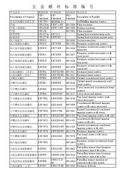
ISO2936 ISO4762 ISO4026 ISO4027 ISO4028 ISO4029
GB5782-86 ISO4014 GB5783-86 ISO4017 ISO2009 GB68-85 GB69-85 GB819-85 GB820-85 GB845-85 GB846-85 GB847-86
方头带垫关圆底端螺栓 T 型槽螺母 单头螺柱 地脚螺栓 带槽圆螺母 端面带孔圆螺母 开槽平端紧定螺钉 开槽锥端紧定螺钉 六角螺母 方螺母 -C 六角头螺钉 六角头圆柱端紧定螺钉 薄型方螺母 -B 六角头木螺钉 吊环螺钉 吊环螺母 六角头螺栓 大半圆头方颈螺栓(马车 螺栓) 沉头带插销马车螺栓 沉头长方颈马车螺栓 半圆头带插销马车螺栓 沉头短方颈马车螺栓 六角头精配螺栓(长螺 纹) 六角头精配螺栓(短螺 栓) 滚花平头螺钉 半圆头铆钉 沉头铆钉 半 沉头铆钉 大扁头铆钉 重型侧面带孔圆螺母 侧面带孔圆螺母 卡头 T 型槽螺钉 双头螺柱(牙长 =2D ) 内六角锥型闭锁螺钉 内六角直型闭锁螺钉 外六角锥型闭锁螺钉 外六角直型闭锁螺钉 薄型盲螺母 开槽小圆柱头螺钉 开槽大圆柱头螺钉
GB6171-86 ISO8673 Hexagon full nuts GB6172.1ISO4035 Hexagon thin nuts 86 GB6172-86 ISO4035 Hexagon thin nuts Slotted raised csk head wood GB101 screws GB99 Slotted round head wood screws Slotted countersunk head wood GB100 screws GB7245-87 Single coil spring lock washers Curved spring washers GB955 Wave spring washers GB37-88 T-head blots with square neck T-head bolts with double nip ISO8737 Taper pins with threaded end T-head bolts Wing nuts America form GB62-88 Wing nuts germany form Wing screws America form Wing screws germany form Ball knobs GB832-88 Slotted capstan screws ISO7435 Slotted set srews with full dog point GB75-85 Slotted set srews with chamfered ISO2342 GB73-85 end GB808-88 Pip nuts with thread GB856-88 External tap ISO7092 Washers for cheese head screws GB848-95 GB852-88 Square taper washers for GB852-88 Square taper washers for Square washers ISO7436 Slotted set with cup point GB74-85 GB6173-86 ISO8675 Hexagon thin nuts Rounds washers for wood ISO7094 constructions Sealing caps,push-in type GB798-88 Eye bolts form B Internal tab washers GB855-88 Washers with two taps GB834-88 Knurled thumb screws with collar Slotted knurled thumb screws with collar GB806-88 Knurled thumb nuts with collar GB807-88 Knurled thumb thin nuts Sealing washers Retaining rings for GB893-86 shafts(external),circlips Retaining rings for GB893.86 bores(internal),circlips Square head bolts with collar Square head bolts with half dog point
五金标准中英文对照表

94 95 96 97 98 99 100 101 102 103 104 105 106 107 108 109 110 111 112 113 114 115 116 117 118 119 120 121 122 123 124 125
DIN914 DIN915 DIN916 DIN917 DIN920 DIN921 DIN923 DIN927 DIN928 DIN929 DIN931 DIN933 DIN934 DIN934 DIN935 DIN936 DIN937 DIN938 DIN939 DIN940 DIN960 DIN961 DIN962 DIN963 DIN964 DIN965 DIN966 DIN970 DIN971 DIN972 DIN975 DIN976
30 31 32 33 34 35 36 37 38 39 40 41 42 43 44 45 46 47 48 49 50 51 52 53 54 55 56 57 58 59 60 61
DIN431 DIN432 DIN433 DIN434 DIN435 DIN436 DIN438 DIN439 DIN439 DIN440 DIN443 DIN444 DIN462 DIN463 DIN464 DIN465 DIN466 DIN467 DIN470 DIN471 DIN472 DIN478 DIN479 DIN480 DIN508 DIN525 DIN529 DIN546 DIN547 DIN551 DIN553 DIN555
pipe nuts with thread external tap washers for cheese head screws square taper washers for Usection square taper washers for Isections square washers slotted set with cup point hexagon thin nuts hexagon thin nuts rounds washers for wood constructions sealing caps,push-in type eye bolts form B internal tab washers washers with two taps knurled thumb screws with collar slotted knurled thumb screws with collar knurled thumb nuts with collar knurled thumb thin nuts sealing washers retaining rings for shafts(external),circlips retaining rings for bores(internal),circlips square head bolts with collar square head bolts with half dog point square head bolts with collar,half dog point and rounded end T-slot nuts single end studs masonry bolts slotted round nuts round nuts with drilled holes in one face slotted sit screws with flat point slotted set screws with cone point hexagon nuts ISO7436 ISO4035 ISO8675 ISO7094 ISO7092
德标与国标以及ISO标准对应

Hexagon head screws Hexagon full nuts Hexagon full nuts Hexagon slotted and castle nuts Hexagon thin nuts Hexagon thin slotted and caslte nuts Studs metal(end=1d)
Mushroom head square neck bolts(carriage bolts) Flat countersunk nib bolts
72 73 74
DIN605 DIN607 DIN608
Flat countersunk long squareneck bolts Cup head nib bolts Flat countersunk short square neck bolts
94 95 96 97 98 99
DIN914 DIN915 DIN916 DIN917 DIN920 DIN921
Hexagon socket set screws with cone point Hexagon socket set screws with dog point Hexagon socket set screws with cup point Hexagon cap nuts Slotted short cheese head screws Slotted large cheese head screws
33
DIN434
33
DIN434
方斜垫圈( taper washers for I-sections Square washers Slotted set with cup point Hexagon thin nuts Hexagon thin nuts Rounds washers for wood constructions Sealing caps,push-in type Eye bolts form B Internal tab washers Washers with two taps Knurled thumb screws with collar Slotted knurled thumb screws with collar Knurled thumb nuts with collar Knurled thumb thin nuts Sealing washers Retaining rings for shafts(external),circlips Retaining rings for bores(internal),circlips Square head bolts with collar Square head bolts with half dog point Square head bolts with collar,half dog point T-slot nuts Single end studs Masonry bolts Slotted round nuts Round nuts with drilled holes in one face Slotted set screws with flat point Slotted set screws with cone point Hexagon nuts Square nuts Hexagon screws Hexagon set screws with full dog point Square nuts without bevel (pressed nuts) Hexgon head wood screw (coach screws) Lifting eye bolts Lifting eye nuts Hexagon blots
射频同轴连接器分类及说明

频段划分_射频同轴连接器分类及说用一.频段的字母表示:自第二次世界大战以来,雷达系统工程师就使用简短的字母来描述雷达工作的波段。
并且这种使用方法一直沿用到今天,而且对于从事相关行业人来说已经成为一个常识。
使用这种字母来表示频段的主要原因是:方便、保密和直观(根据字母就可知系统相关特性)。
根据IEEE 521-2002标准,雷达频段字母命名和ITU(国际电信联盟)命名对比如下表所示:二.同轴连接器发展概况及相关标准1射频连接器的发展概况:1.1.1939年出现的UHF连接器是最早的RF连接器;1.2.二战期间随着雷达、电台和微波通信的发展产生了N,C,BNC,TNC等中型系;1.3.1958年后,随着整机设备的小型化,出出现了SMA,SMB,SMC等小型化产品;1.4.1964年制定了美国军用标准MIL-C-39012《射频同轴连接器总规范》;1.5.七十年代末,毫米波连接器出现;1.6.九十年代初,HP公司推出频率高达110GHz的1.0mm连接器,并用于其仪器设备中;1.7.九十年代出现表面贴装射频同轴连接器并大量用于手机产品中;2我国射频同轴连连接器的发展:2.1我国从五十年代开始由整机厂研制RF连接器;2.2六十年代末组建专业工厂,开始了专业化生产;2.3一九七二年国家组织集中设计,使国产的RF连接器是自成系统,只能在国内使用,产品标准水平低,且不能与国际通用产品对接互换;2.4八十年代起开始采用国际标准,根据IEC169和MIL-C-39012,颁布了GB11313和GJB681,使射频同轴连接器的生产和使用逐步与国际接轨;2.5经过几十年的努力,目前通用RF连接器的整体水平与国外差距不大,但精密连接器的设计和生产与国外仍有较大差距;3射频连接器的标准体系;3.1美军标及其他它先进标准:美国是世界上最大的通用型RF连接器制造和消费国,其水平也是一流的,因此美国军用标准MIL-C-39012被认为是RF连接器的最高标准;3.2IEC标准:IEC是指导性标准,不是强制性标准,因此很少被直接应用;4其它先进标准:德国的DIN、英国BS,日本JIS;这些国家的标准大都是参照或等同美军标制订的有些国家甚至直接应用美军标,而不再另行制订标准;值得一提的是,德国在某些专用新型连接器方面也有一些优势,例如:DIN47223的7/16(L29)系列、DIN47297的SAA系列及DIN41626的DSA系列等。
DIN-ISO-GB标准件对照表
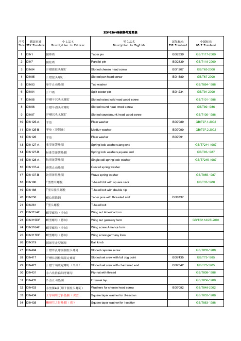
国际标准 ISO-Standard
ISO2339 ISO2339 ISO1207 ISO1580
ISO1234
ISO7089 ISO7090 ISO7091
中国标准 GB/T-Standard GB/T117-2000 GB/T119-2000 GB/T65-2000 GB/T67-2000 GB/T854-1988 GB/T91-2000 GB/T101-1986 GB/T99-1986 GB/T100-1986 GB/T97.1-2002 GB/T97.2-2002
DIN-ISO-GB标准件对照表
序号 德国标准 Item DIN-Standard
中文品名 Description in Chinese
英文品名 Desciption in English
1 DIN1 2 DIN7 3 DIN84 4 DIN85 5 DIN93 6 DIN94 7 DIN95 8 DIN96 9 DIN97 10 DIN125-A 11 DIN125-B 12 DIN126 13 DIN127-A 14 DIN127-B 15 DIN128-A 16 DIN137-A 17 DIN137-B 18 DIN186 19 DIN188 20 DIN258 21 DIN261 22 DIN315AF 23 DIN315DF 24 DIN316AF 25 DIN317DF 26 DIN319 27 DIN404 28 DIN417 29 DIN427 30 DIN431 31 DIN432 32 DIN433 33 DIN434 34 DIN435
方垫圈
Square washer
开槽凹端紧定螺钉
Slotted set with cup point
六角薄螺母
DIN标准件
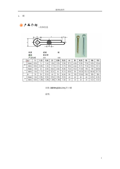
1.销->具体信息名称: DIN94(ISO1234)开口销说明:->具体信息名称: DIN7979(GB120.2)内螺纹圆柱销说明: 内径规格:M4 - M24->具体信息名称: DIN7(GB119.2)圆柱销说明:->具体信息名称: DIN6325圆柱销说明:->具体信息名称: DIN1481(ISO8752)弹性圆柱销说明:->具体信息名称: DIN1475(GB13829.2)开槽销说明:->具体信息名称: DIN1(GB117)圆锥销说明:2.挡圈:->具体信息名称: DIN7993(GB921)钢丝锁圈说明:->具体信息名称: DIN6799(GB896)开口挡圈说明:->具体信息名称: DIN472孔用弹性挡圈说明:->具体信息名称: DIN471轴用弹性挡圈说明:3.锁紧垫圈:->具体信息名称: DIN7980弹簧锁紧垫圈说明: Single Coil Spring Lock Washers->具体信息名称: DIN6798V内锯齿锁紧垫圈(V型)说明: Serrated Countersunk Lock Washers External Gear->具体信息名称: DIN6798J内锯齿锁紧垫圈说明: Toothed Lock Serrated Internally Washers->具体信息名称: DIN6798外锯齿锁紧垫圈说明: Serrated Lock Washers External Gear Type A->具体信息名称: DIN6797J内齿锁紧垫圈说明: 垫圈内径: 1.7 - 7.4垫圈外径: 3.6 - 12.5->具体信息名称: DIN6797A外齿锁紧垫圈说明: 垫圈内径: 1.7 - 7.4垫圈外径: 3.6 - 12.54.弹垫:->具体信息名称: DIN137B波形弹性垫圈说明: Waved Spring Washers B->具体信息名称: DIN137鞍形弹性垫圈说明: Waved Spring Washers Type A->具体信息名称: DIN127B弹簧垫圈说明: Single Coil Lock Washers5.平垫:->具体信息名称: DIN988薄型平垫圈说明: Shim Rings->具体信息名称: DIN9021大平垫圈说明: Flat Washers->具体信息名称: DIN7349平垫圈(用在弹性圆柱销上)说明: Washers->具体信息名称: DIN433平垫圈说明: Washers->具体信息名称: DIN125B平垫圈说明: Product W/O Chamfer Washers->具体信息名称: DIN125A平垫圈说明: Product W/O Chamfer Washers6.螺栓:->具体信息名称: DIN933外六角螺栓(全牙)说明: Hexagon Head Bolts->具体信息名称: DIN931外六角螺栓(半牙)说明: Hexagon Head Bolts->具体信息名称: DIN6921六角法兰螺栓说明: Hexagon Flange Bolts->具体信息名称: DIN604沉头带榫螺栓说明: Flat Countersunk Nib Bolts->具体信息名称: DIN261T型螺栓说明: T-Head Bolts->具体信息名称: DIN444活节螺栓说明: Eye Bolts->具体信息名称: DIN939双头螺栓说明: Studs Thread->具体信息名称: DIN603马车螺栓(半圆头方颈螺栓)说明: Mushroom Head Square Bolts->具体信息名称: DIN316蝶型螺栓说明: Wing Screws->具体信息名称: DIN580吊环螺栓说明: Lifting Eyebolts7.螺钉:->具体信息名称: DIN7991内六角沉头螺钉说明: Hexagon socket Countersunk head Screws。
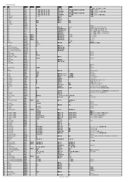
中德标准件对照表
DIN标准整理

DIN标准 DIN988 DIN1013 DIN1048 DIN1440 DIN1473 DIN1475 DIN1476 DIN1481 DIN1712 DIN1752 DIN1783 DIN1804 DIN1850 DIN3121 DIN3962 DIN3967 DIN5817 DIN6305 DIN6325 DIN6336 DIN6798-A DIN6798-I DIN6885 DIN6886 DIN6912 DIN6921 DIN7168 DIN7169 DIN7271 DIN7349 DIN7979 DIN7981 DIN7984 DIN7991 DIN7993
光拔六角钢尺寸,允许偏差及重量
名称 齿轮等级标准 研磨齿轮等级标准 螺纹标准 固定手柄 螺栓沉头孔标准 螺纹退刀槽标准 滚花标准 开槽圆柱头螺钉 开槽盘头螺钉 单耳止动垫圈 开口销 开槽半沉头木螺钉 开槽半圆头木螺钉 开槽沉头木螺钉 旋转手柄 铆钉交货技术条件
德标对照
国标对照
类别 技术标准 技术标准 技术标准 标准件 技术标准 技术标准 技术标准
标准件 标准件 标准件 标准件 标准件 标准件 标准件 标准件 标准件 标准件 材料标准
技术标准 技术标准
冷拔圆钢丝尺寸,极限尺寸偏 差,重量 塑料抗弯性能测定 衬套 第 1 页,共 4 页
标准件
DIN标准 DIN186 DIN188 DIN202 DIN254 DIN258 DIN261 DIN267 DIN276 DIN319 DIN434 DIN435 DIN439 DIN439 DIN444 DIN470 DIN471 DIN472 DIN475 DIN509 DIN551 DIN553 DIN580 DIN625 DIN705 DIN766 DIN867 DIN912 DIN913 DIN915 DIN917 DIN923 DIN933 DIN934 DIN938 DIN939 DIN975-1970 DIN985
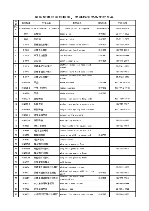
德国DIN标准件ISO及国标对照表
DIN 472 2011 德国卡簧标准
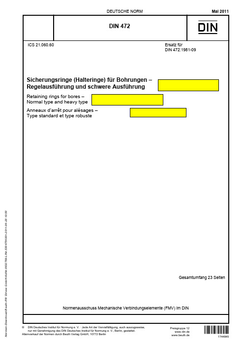
11 Bezeichung...................................................................................................................................... 23
Gesamtumfang 23 Seiten
Normenausschuss Mechanische Verbindungselemente (FMV) im DIN
© DIN Deutsches Institut für Normung e. V. · Jede Art der Vervielfältigung, auch auszugsweise, nur mit Genehmigung des DIN Deutsches Institut für Normung e. V., Berlin, gestattet.
8
Tragfähigkeit ................................................................................................................................... 19
8.1 Allgemeines..................................................................................................................................... 19
8.2 Tragfähigkeit der Nut FN ................................................................................................................ 19
德国DIN标准件ISO及国标对照表

序号 德国标准 中文品名 英文品名 Description in English taper pins parallel pins slotted cheese head screws slotted pan head screws tab washers split cotter pins slotted raised csk head wood screws slotted round head wood screws slotted countersunk head wood screws plain washers mediun washers plain washers spring lock washers,tang ends spring lock washers,square ends single coil spring lock washers curved spring washers wave spring washers T-head bolts with square neck T-head bolts with double nip taper pins with threaded end T-head bolts wing nuts amercia form wing nuts germany form wing screws amercia form wing screws germany form ball knobs GB/T832-1988 ISO7435 ISO2342 GB/T75-1985 GB/T73-1985 GB/T808-1988 GB/T856-1988 ISO7092 GB/T848-1985 GB/T62-1988 ISO8737 GB/T955-1987 GB/T37-1988 ISO7089 ISO7090 ISO7091 GB/T7244-1987 GB/T93-1987 GB/T7245-1987 国际标准 ISO-Standard ISO2339 ISO2338 ISO1207 ISO1580 ISO1580 ISO1234 中国标准 GB-Standard GB/T117-2000 GB/T119-2000 GB/T65-2000 GB/T67-2000 GB/T854-1998 GB/T91-2000 GB/T101-1986 GB/T99-1986 GB/T100-1986 GB/T97.1-1985 GB/T97.2-1985 Item DIN-Standard Description in Chinese 1 2 3 4 5 6 7 8 9 10 11 12 13 14 15 16 17 18 19 20 21 22 23 24 25 26 27 28 29 30 31 32 DIN1 DIN7 DIN84 DIN85 DIN93 DIN94 DIN95 DIN96 DIN97 DIN125-A DIN125-B DIN126 DIN127-A DIN127-B DIN128-A DIN137-A DIN137-B DIN186 DIN188 DIN258 DIN261 DIN315AF DIN315DF DIN316AF DIN317DF DIN319 DIN404 DIN417 DIN427 DIN431 DIN432 DIN433 圆锥销 圆柱销 开槽圆柱头螺钉 开槽盘头螺钉 单耳止动垫圈 开口销 开槽半沉头木螺钉 开槽半圆头木螺钉 开槽沉头木螺钉 平垫 平垫(带倒角) 平垫 重型弹垫 标准弹垫 鞍形弹垫 弹簧止动垫圈 波形弹垫 T型方颈螺栓 T型双接头螺栓 螺纹圆锥销 T型头螺栓 蝶型螺母(美制) 蝶型螺母(德制) 蝶型螺钉(美制) 蝶型螺钉(德
常见射频同轴连接器大全(特制材料)

常见射频同轴连接器大全射频信号有自己的特点,所以传输信号需要特别的媒介,而相应连接器也很特殊,这里主要介绍常见的射频同轴连接器(RF COAXIAL CONNECTOR),符合标准GB11316-89、IEC169、MIL-C-31012等标准。
一、常见的同轴连接器及主要性能对照表:除上述连接器以外,还有MINI BNC、SL16、C3、CC4(1.0/2.3)、SMZ(BT-43)、MIM等连接器,但主要是一些公司的型号。
二、常见同轴连接器的选择:BNC是卡口式,多用于低于4GHz的射频连接,广泛用于仪器仪表及计算机互联TNC是螺纹连接,尺寸等方面类似BNC,工作频率可达11GHz,螺纹式适合振动环境SMA是螺纹连接,应用最广泛,阻抗有50和75欧姆两种,50欧姆时配软电缆使用频率低于12.4Ghz,配半刚性电缆最高到26.5GHzSMB体积小于SMA,为插入自锁结构,用于快速连接,常用于数字通讯,是L9的换代品,50欧姆可到4 GHz,75欧姆到2GHzSMC为螺纹连接,其他类似SMB,有更宽的频率范围,常用于军事或高振动环境N型连接器为螺纹式,以空气为绝缘材料,造价低,频率可达11GHz,常用于测试仪器上,有50和75欧姆两种MCX和MMCX连接器体积小,用于密集型连接BMA用于频率达18GHz的低功率微波系统的盲插连接每种连接器都有军标和商业标准,军标按MIL-C-39012制造,全铜零件、聚四氟乙烯绝缘、内外镀金,性能最可靠,但造价较高。
商业标准设计则使用廉价材料,如黄铜铸体、聚丙烯绝缘、银镀层等,可靠性就差一些。
连接器材料有黄铜、铍铜和不锈钢,中心导体一般镀金,保证低电阻和耐腐蚀。
军标要求在SMA和SMB 上镀金,在N、TNC及BNC上镀银,因为银易氧化,用户更喜欢镀镍。
绝缘材料有聚四氟乙烯、聚丙烯及韧化聚苯乙烯,其中聚四氟乙烯绝缘性能最好,但成本较高。
三、常用连接器的性能列表:1.L29(7/16)标准:IEC169-4、CECC22190、DIN47223特点:较大型螺纹式中高能量传输温度范围:-40~+85耐久性:500次PLUG内径/JACK内径:21mm/22.5mm电气性能:特性阻抗:50欧姆工作电压:2700Vrms频率范围:0-7.5GHz介质耐压:4000Vrms接触电阻:内导体<0.4mOhm,外导体<1.5mOhm 绝缘电阻:>10000兆欧VSWR:<1.30材料:壳体:黄铜镀镍或银插针:黄铜镀硬金或银插孔:锡青铜镀硬金或银绝缘体:聚四氟乙烯密封件:硅橡胶压接套:铜合金镀镍2.N标准:MIL-C-39012、IEC169-16、CECC22210 特点:螺纹式中大功率温度范围:-65~+165耐久性:500次PLUG内径/JACK内径:16mm/8.6mm电气性能:特性阻抗:50欧姆工作电压:1000Vrms频率范围:0-11GHz介质耐压:1500V接触电阻:内导体<1mOhm,外导体<0.2mOhm 绝缘电阻:>5000兆欧VSWR:<1.30材料:壳体:黄铜镀镍插针:黄铜镀硬金插孔:铍青铜镀硬金或锡青铜镀金绝缘体:聚四氟乙烯密封件:硅橡胶压接套:铜合金镀镍3.BNC标准:MIL-C-39012、IEC169-8特点:卡口式温度范围:-65~+165耐久性:500次PLUG内径/JACK内径:9.8mm/9.6mm电气性能:特性阻抗:50/75欧姆工作电压:500V频率范围:0-4GHz介质耐压:1500V接触电阻:内导体<1.5mOhm,外导体<1mOhm 绝缘电阻:>5000兆欧VSWR:<1.30材料:壳体:黄铜镀镍插针:黄铜镀硬金插孔:铍青铜或锡青铜镀硬金绝缘体:聚四氟乙烯压接套:铜合金镀镍4.TNC标准:MIL-C-39012、IEC169-17特点:螺纹式温度范围:-65~+165耐久性:500次PLUG内径/JACK外径:11mm/9.6mm电气性能:特性阻抗:50欧姆工作电压:500V频率范围:0-11GHz介质耐压:1500V接触电阻:内导体<1.5mOhm,外导体<0.2mOhm 绝缘电阻:>5000兆欧VSWR:<1.3材料:壳体:黄铜镀镍插针:黄铜镀硬金插孔:铍青铜镀硬金绝缘体:聚四氟乙烯密封件:硅橡胶压接套:铜合金镀镍5.L9(1.6/5.6)标准:IEC169-13、CECC22240、DIN47295特点:小型螺纹式温度范围:-40~+85耐久性:500次PLUG内径/JACK内径:8.2mm/4mm电气性能:特性阻抗:75欧姆工作电压:330V频率范围:0-1GHz介质耐压:1000V接触电阻:内导体<10mOhm,外导体<5mOhm 绝缘电阻:>10000兆欧材料:壳体:黄铜镀镍或金插针:黄铜镀硬金插孔:铍青铜镀硬金绝缘体:聚四氟乙烯压接套:铜合金镀镍或金6.SMA标准:MIL-C-39012、IEC169-15、CECC22110 特点:小型螺纹式温度范围:-65~+165耐久性:500次PLUG内径/JACK外径:6.5mm/5.4mm电气性能:特性阻抗:50欧姆工作电压:335Vrms频率范围:0-12.4GHz(软电缆)/0-18GHz(半刚性电缆) 介质耐压:1000Vrms接触电阻:内导体<3mOhm,外导体<2mOhm绝缘电阻:>5000兆欧插入损耗:0.15dB(6GHz)射频泄漏:-60dB/-90dB(软电缆/半刚电缆)@2-3GHz VSWR:直式软性电缆<1.15+0.02f(GHz)弯式软性电缆<1.20+0.03f(GHz)弯式半刚电缆<1.05+0.01f(GHz)弯式半刚电缆<1.10+0.01f(GHz)材料:壳体:黄铜镀硬金或不锈钢表面钝化插针:黄铜镀硬金插孔:铍青铜镀硬金绝缘体:聚四氟乙烯密封件:硅橡胶压接套:铜合金镀镍7.SMB标准:MIL-C-39012、IEC169-10、CECC22130特点:小型推入锁紧式温度范围:-65~+165耐久性:500次PLUG接触杆外径/JACK内径:2mm/3.7mm电气性能:特性阻抗:50/75欧姆工作电压:250V频率范围:0-4GHz(50欧姆)/0-2GHz(75欧姆)介质耐压:750V接触电阻:内导体<6mOhm,外导体<1mOhm 绝缘电阻:>1000兆欧VSWR:<1.34材料:壳体:黄铜镀硬金弹性接触杆:铍青铜镀硬金插针:黄铜镀硬金绝缘体:聚四氟乙烯压接套:铜合金镀镍或镀金8.SMC标准:MIL-C-39012、IEC169-18、CECC22140 特点:小型螺纹式温度范围:-65~+165耐久性:500次PLUG内径/JACK外径:3.8mm/3.7mm电气性能:特性阻抗:50欧姆工作电压:250V频率范围:0-10GHz介质耐压:750V接触电阻:内导体<6mOhm,外导体<1mOhm 绝缘电阻:>1000兆欧VSWR:直式<1.25 弯式<1.35材料:壳体:黄铜镀硬金插针:黄铜镀硬金插孔:铍青铜镀硬金绝缘体:聚四氟乙烯压接套:铜合金镀镍或镀金9.BMA标准:IEC169-33特点:微型推入式温度范围:-65~+155耐久性:500次PLUG外径/JACK外径:5.3mm/7.4mm电气性能:特性阻抗:50欧姆工作电压:250V频率范围:0-18GHz介质耐压:750V接触电阻:内导体<3mOhm,外导体<2mOhm 绝缘电阻:>5000兆欧VSWR:<1.30材料:壳体:黄铜镀硬金或镍及不锈钢钝化插针:黄铜镀硬金插孔:铍青铜镀硬金绝缘体:聚四氟乙烯压接套:铜合金镀镍10.SSMA标准:MIL-C-39012、IEC169-18、CECC22140 特点:微型螺纹式温度范围:-55~+155耐久性:500次PLUG内径/JACK外径:5mm/4mm电气性能:特性阻抗:50欧姆工作电压:250V频率范围:0-35GHz介质耐压:750V接触电阻:内导体<4mOhm,外导体<2.5mOhm 绝缘电阻:>1000兆欧VSWR:<1.07+0.1f(GHz)材料:壳体:黄铜镀硬金插针:黄铜镀硬金插孔:铍青铜镀硬金绝缘体:聚四氟乙烯压接套:铜合金镀镍或镀金11.SSMB标准:IEC169-19、CECC22170特点:微型推入式温度范围:-55~+155耐久性:500次PLUG内径/JACK外径:4.5mm/2.7mm电气性能:特性阻抗:50欧姆工作电压:250V频率范围:0-11GHz介质耐压:500V接触电阻:内导体<5mOhm,外导体<2.5mOhm绝缘电阻:>1000兆欧VSWR:直式<1.22(0-1GHz) <1.35(0-3GHz) 弯式<1.50(0-1GHz) <1.63(0-3GHz)材料:壳体:黄铜镀硬金插针:锡青铜镀硬金插孔:铍青铜镀硬金绝缘体:聚四氟乙烯压接套:铜合金镀镍或镀金12.MCX(OSX)标准:CECC22220特点:小型插接自锁式温度范围:-65~+155耐久性:500次PLUG外径/JACK内径:3.7mm/3.45mm电气性能:特性阻抗:50/75欧姆频率范围:0-6GHz(50欧姆) 0-1.5GHz(75欧姆) 介质耐压:750V接触电阻:内导体<5mOhm,外导体<2.5mOhm 绝缘电阻:>1000兆欧VSWR:<1.20(50欧姆) <1.35(75欧姆)材料:壳体:黄铜镀硬金弹性接触件:铍青铜镀硬金插针:黄铜镀硬金插孔:铍青铜镀硬金绝缘体:聚四氟乙烯压接套:铜合金镀镍或镀金13.MMCX(C2.5)标准:CECC22340特点:微型插接自锁式温度范围:-40~+90耐久性:500次PLUG外径/JACK内径:2.4mm/3mm电气性能:特性阻抗:50欧姆工作电压:170V频率范围:0-6GHz介质耐压:500V接触电阻:内导体<10mOhm,外导体<5mOhm绝缘电阻:>1000兆欧VSWR:<1.25材料:壳体:黄铜镀硬金弹性接触件:铍青铜镀硬金插针:黄铜镀硬金插孔:铍青铜镀硬金绝缘体:聚四氟乙烯压接套:铜合金镀镍或镀金14.SAA(1.0/2.3)标准:CECC22230、DIN47297特点:直插锁紧式温度范围:-65~+155耐久性:500次PLUG内径/JACK内径:2.3mm/4.1mm电气性能:特性阻抗:50/75欧姆工作电压:250V频率范围:0-4.8GHz(50欧姆)/0-1.65GHz(75欧姆) 介质耐压:750V接触电阻:内导体<10mOhm,外导体<7.5mOhm 绝缘电阻:>1000兆欧VSWR:直式<1.25 弯式<1.40材料:壳体:黄铜镀硬金弹性接触杆:铍青铜镀硬金插针:黄铜镀硬金插孔:铍青铜镀硬金绝缘体:聚四氟乙烯压接套:铜合金镀镍15.MSP标准:NEC公司产品特点:推入自锁式温度范围:-65~+165耐久性:500次PLUG内径/JACK内径:5mm/4mm电气性能:特性阻抗:75欧姆频率范围:0-1GHz介质耐压:750V接触电阻:内导体<10mOhm,外导体<4mOhm绝缘电阻:>1000兆欧VSWR:<1.25材料:壳体:黄铜镀镍插针:黄铜镀硬金插孔:铍青铜镀硬金或锡青铜镀金绝缘体:聚四氟乙烯密封件:硅橡胶压接套:铜合金镀镍16.C4(1.0/2.3)标准:DIN41626特点:小型推入式温度范围:-55~+125耐久性:500次PLUG外径/JACK内径:4.7mm/3mm电气性能:特性阻抗:50/75欧姆工作电压:250V频率范围:0-2GHz(50欧姆) 0-1.5GHz(75欧姆) 介质耐压:750V接触电阻:内导体<10mOhm,外导体<5mOhm 绝缘电阻:>1000兆欧材料:壳体:黄铜镀硬金弹性接触件:铍青铜镀硬金插针:黄铜镀硬金插孔:铍青铜镀硬金绝缘体:聚四氟乙烯压接套:铜合金镀镍或金。
紧固件标准件螺栓螺母标准对照
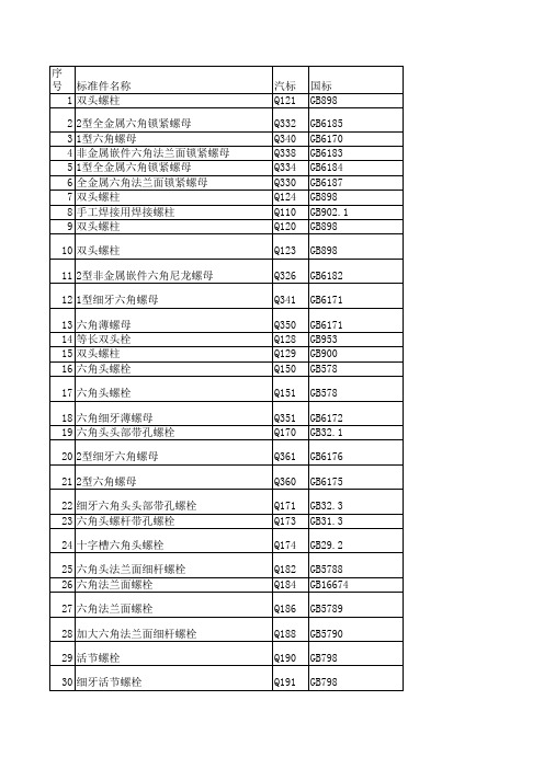
Q551 GB1096-1979
Q611 Q382-1999 Q614B Q379-1999 Q615 Q377-1999
Q616 Q377-1999 Q617B Q376-1999 Q618B Q381-1999 Q620 Q386-1999 Q619 Q378-1999 Q308 Q354-1999 Q309 Q354-1999
119 滚花圆柱销
120 六角头平垫组合螺栓 121 六角头锥形弹性垫圈组合螺栓 122 六角头弹垫组合螺栓
123 六角头外锯齿锁紧垫圈组合螺栓 124 六角头弹垫平垫组合螺栓 125 十字槽盘头平垫组合自攻螺钉 126 十字槽盘头大平垫组合自攻螺钉 127 十字槽盘头平垫组合螺钉
128 十字槽盘头弹垫组合螺钉
中文品名
螺丝标准及国标德标国际标准 德国标准
自攻自钻螺钉多种头型 平垫 平垫(带倒角) 平垫 重型弹垫 标准弹垫 内六角扳手 内六角圆柱头螺钉
DIN7504 DIN125-A DIN125-B DIN126 DIN127-A DIN127-B DIN911 DIN912
内六角平端紧定螺钉
DIN913
相关标准
ISO7042 ISO4032 ISO7043 ISO7919 ISO7044
ISO7041 ISO8673 ISO4035
ISO4014-1988、ISO4017-1988 ISO8675-1988、ISO8676-1988 ISO8675 GB5783 ISO8674
GB5786 GB5786
Q453 Q454 Q460
GB871-1986 GB873-1986 GB869-1986
Q465 GB876-1986
Q470 Q472 Q476
液氨钢瓶标准-概述说明以及解释

液氨钢瓶标准-概述说明以及解释1.引言1.1 概述液氨钢瓶标准是指用于贮存和运输液态氨的钢制容器所需要遵守的一系列规范和要求。
液氨钢瓶广泛应用于农业、化工、医药等行业,在液化氨的收运、存储和使用过程中具有至关重要的作用。
本文旨在系统地介绍液氨钢瓶标准的相关内容,包括定义、用途、制造标准以及对标准的重要性和建议展望。
首先,我们将详细解释液氨钢瓶的定义和用途。
液氨钢瓶是一种专门用于贮存和运输液态氨的钢制容器。
液态氨是一种具有强烈刺激性气味的无色、无味的化学物质,具有广泛的应用领域。
液氨钢瓶在农业中被用于作为植物肥料的供应源,可以提供植物所需的氮元素;在化工工业中,液氨钢瓶则是合成化学产品的重要原料;在医药行业,液氨钢瓶也用于制备药品和医疗材料。
其次,我们将详细介绍液氨钢瓶的制造标准。
液氨钢瓶的制造应遵循一系列的技术要求和标准,包括材料选择、生产工艺、外观检验等。
这些标准的制定旨在确保液氨钢瓶的安全可靠,从而保障生产和使用过程中的人身安全和财产安全。
通过对液氨钢瓶的制造标准进行详细的介绍,我们可以更好地理解液氨钢瓶的质量控制和监管机制。
最后,我们将探讨液氨钢瓶标准的重要性和提出建议展望。
液氨钢瓶标准的制定对于确保液氨的贮存和运输安全至关重要。
严格遵守标准可以有效减少事故的发生,保护人员和环境的安全。
然而,目前液氨钢瓶标准还存在一些问题,如制定不规范、落后于实际应用等。
因此,我们提出了一些建议,包括加强标准制定的科学性和针对性、推动标准与实际应用的紧密结合等方面的改进。
通过本文的详细介绍和论述,读者能够更全面地了解液氨钢瓶标准的意义和要求,同时也能够对液氨钢瓶标准的改进方向有所了解。
本文的目的是为进一步提高液氨钢瓶质量和安全性提供参考和指导,促进液氨钢瓶行业的健康发展。
1.2 文章结构本文将以液氨钢瓶标准为主题,通过以下几个部分进行详细介绍和分析。
首先,我们将在引言部分中对本文的内容进行概述,包括液氨钢瓶的定义、用途以及制造标准的重要性。
德国DIN标准件ISO及国标对照表

47
DIN467 滚花薄螺母
knurled thumb thin nuts
GB/T807-1988
48
DIN470 锁紧垫圈
sealing washers
49
DIN471 轴用弹性挡圈
50
DIN472 孔用弹性挡圈
retaining rings for shafts(external),circlips retaining rings for bores(internal),circlips
GB/T67-2000
5
DIN93 单耳止动垫圈
tab washers
ISO1580
GB/T854-1998
6
DIN94 开口销
7
DIN95 开槽半沉头木螺钉
8
DIN96 开槽半圆头木螺钉
9
DIN97 开槽沉头木螺钉
10 DIN125-A 平垫
split cotter pins
slotted raised csk head wood screws
hexagon nuts
ISO4776 ISO7434 ISO4034
GB/T817-1988 GB/T815-1988 GB/T73-1985 GB/T71-1985
62
DIN557 方螺母-C
square nuts
GB/T39-1988
德国标准和国际标准、中国标准中英文对照表
序 号
德国标准
中文品名
纹)
thread
77
DIN653 滚花平头螺钉
knurled thumb screws thin type
GB/T14-1988 GB/T835-1988
德国DIN标准件ISO及国标对照表

slotted countersunk head wood screws
plain washers
ISO1234 ISO7089
GB/T91-2000 GB/T101-1986 GB/T99-1986 GB/T100-1986 GB/T97.1-1985
ISO4029
ISO4776 ISO7434 ISO4034
62
DIN557 方螺母-C
square nuts
63
DIN558 六角头螺钉
hexagon screws
64
DIN561
六角头圆柱端紧定螺钉
hexagon set screws with full dog point
ISO4018
中国标准 GB/T852-1988 GB/T852-1988
GB/T39-1988
序 号
德国标准
中文品名
65
DIDIN571 六角头木螺钉
67
DIN580 吊环螺钉
英文品名
square nuts without bevel(pressed nuts) hexagon head wood screws (coach screws)
GB/T74-1985 GB/T6172-2000 GB/T6173-2000
GB/T798-1988
GB/T855-1988 GB/T834-1988
GB/T806-1988 GB/T807-1988
GB/T894.1-1986 GB/T893.1-1986
GB/T799-1988 GB/T817-1988 GB/T815-1988 GB/T73-1985 GB/T71-1985
DIN472_孔用卡簧
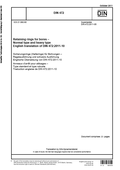
October 2011Translation by DIN-Sprachendienst.English price group 12No part of this translation may be reproduced without prior permission ofDIN Deutsches Institut für Normung e. V., Berlin. Beuth Verlag GmbH, 10772 Berlin, Germany,has the exclusive right of sale for German Standards (DIN-Normen).ICS 21.060.60!$y6q"1861978www.din.de DDIN 472Retaining rings for bores –Normal type and heavy typeEnglish translation of DIN 472:2011-10Sicherungsringe (Halteringe) für Bohrungen –Regelausführung und schwere Ausführung Englische Übersetzung von DIN 472:2011-10Anneaux d’arrêt pour alésages –Type standard et type robusteTraduction anglaise de DIN 472:2011-10©SupersedesDIN 472:2011-05www.beuth.deDocument comprises pagesIn case of doubt, the German-language original shall be considered authoritative.2301.12DIN 472:2011-102 A comma is used as the decimal marker.ContentsPageForeword (3)1 Scope (4)2 Normative references (4)3 Symbols (5)4 Dimensions and design details (6)5 Material (16)6 Finish (16)7 Testing (17)7.1 Testing the material (17)7.2 Bend and fracture test (17)7.3 Testing the deformation (17)7.3.1 Testing the conical deformation (17)7.3.2 Testing the spiral flatness (18)7.4 Testing the function (permanent set and grip test) (18)7.5 Acceptance inspection (19)8 Load bearing capacity (19)8.1 General (19)8.2 Load bearing capacity of groove F N (19)8.3 Load bearing capacity of retaining ring F R (20)9 Design of the groove (21)9.1 Groove diameter d2 (21)9.2 Groove width m (21)9.3 Design of the groove base (22)10 Assembly (23)11 Designation (23)DIN 472:2011-103ForewordThis standard has been prepared by Working Committee NA 067-00-09 AA Verbindungselemente ohne Gewinde of the Normenausschuss Mechanische Verbindungselemente (Fasteners Standards Committee). Attention is drawn to the possibility that some of the elements of this document may be the subject of patent rights. DIN shall not be held responsible for identifying any or all such patent rights.The DIN 4000-162-5 tabular layout of product properties shall apply to retaining rings covered in this standard. AmendmentsThis standard differs from DIN 472:1981-09 as follows: a) normative references have been updated;b) use of other materials subject to agreement is no longer permitted;c) the tolerances on radial run-out have been deleted from Figure 2 (formerly Figure 3); d) Figure 10 “Design of groove base” has been included in 9.3;e) in Clause 10 (formerly Clause 9), Figure 11 (formerly Figure 14) has been revised; f)examples of designation for retaining rings with corrosion protection have been included;g) the specifications for load bearing capacity and assembly have been revised; h) the standard has been editorially revised.Compared with DIN 472:2011-05 the following corrections have been made:a) in the list of amendments items c) and e) have been rendered more precise and item d) has beencorrected; b) Figures 6 and 7 have been corrected;c) in 7.4, the reference to the associated figure has been corrected;d) in 8.3, the first paragraph has been deleted (identical in content with second paragraph); e) the illustration of the shaft in Figures 9 a) to 9 d) has been brought in line with Figure 2; f)a reference to the standard covering the relevant tabular layout of product properties has been included.Previous editionsDIN 471 and DIN 472 Supplement 1: 1945-01, 1954x-03DIN 472: 1941-12, 1942-11, 1952-01, 1954x-01, 1981-09, 2011-05 DIN 472-1: 1965-03 DIN 472-2: 1965-03 DIN 995: 1970-01DIN 472:2011-1041 ScopeThis standard specifies requirements for retaining rings for bores and lays down design details for the grooves into which such rings are fitted.NOTE Retaining rings are used to hold components or assemblies (e.g. rolling bearings) in bores and are suitable for the transmission of axial forces.2 Normative referencesThe following referenced documents are indispensable for the application of this document. For dated references, only the edition cited applies. For undated references, the latest edition of the referenced document (including any amendments) applies. DIN 988, Shim rings and supporting ringsDIN 4000-162, Tabular layout of properties — Part 162: Washers and rings DIN 5256, Pliers for retaining rings for boresDIN 50938, Black oxide coatings on iron or steel — Requirements and test methodsDIN EN 10132-4, Cold-rolled narrow steel strip for heat-treatment — Technical delivery conditions — Part 4: Spring steels and other applicationsDIN EN 12476, Phosphate conversion coatings of metals — Method of specifying requirements DIN EN ISO 3269, Fasteners — Acceptance inspection DIN EN ISO 4042, Fasteners — Electroplated coatingsDIN EN ISO 6507-1, Metallic materials — Vickers hardness test — Part 1: Test methodDIN EN ISO 6508-1, Metallic materials — Rockwell hardness test — Part 1: Test method (scales A, B, C, D, E, F, G, H, K, N, T)DIN EN ISO 9227, Corrosion tests in artificial atmospheres — Salt spray tests DIN EN ISO 18265, Metallic materials — Conversion of hardness valuesDIN ISO 2859-1, Sampling procedures for inspection by attributes — Part 1: Sampling schemes indexed by acceptance quality limit (AQL) for lot-by-lot inspectionDIN 472:2011-1053 Symbolsa radial width of the lugb radial width of retaining ring opposite the aperturec distance between measuring plates for testing spiral flatnessd 1 bore diameter d 2 groove diameterd 3 external diameter of retaining ring in the unstressed stated 4 minimum centre line diameter of bore during assembly, calculated as: d 4 = d 1 – 2,1 ad 5 diameter of the assembly holes E modulus of elasticityF force acting on the retaining ring when testing conical deformationF N load bearing capacity of groove at a yield point of the grooved material of 200 MPa (see 8.2) F R load bearing capacity of retaining ring with sharp-edged abutment of a machine component (see 8.3) F Rg load bearing capacity of retaining ring for abutment with edge distance g (see 8.3) g edge distance of the machine component abutting the retaining ring h distance between the plates when testing conical deformation m groove width n edge margin R eL yield pointr curvature in the groove base or test jaws s thickness of retaining ringtgroove depth with nominal sizes of d 1 and d 2DIN 472:2011-1064 Dimensions and design detailsThe designs shown in Figure 1 are for illustrative purposes only; however, the dimensions of retaining rings and grooves shall be as specified in Tables 1 and 2. The tolerances specified relate to retaining rings in their uncoated condition.UnstressedShape of ring at manufacturer’s discretiona)b)Detail Xd 1 ≤ 300 mmd 1 ≥ 170 mm at manufacturer’sdiscretiond 1 ≥ 25 mm atmanufacturer’s discretionKey 1BoreFigure 1 — Dimensions of retaining ring (notation)DIN 472:2011-10Figure 2 — Example of installationValues for peak-to-valley height for groove base and loaded edge shall be specified on a case-by-case basis. The design of the groove base shall be as specified in 9.3.7DIN 472:2011-108 Table 1 — Normal typeDIN 472:2011-10 Table 1(continued)9DIN 472:2011-1010 Table 1(continued)DIN 472:2011-10 Table 1 (continued)11DIN 472:2011-1012 Table 1 (continued)DIN 472:2011-10 Table 1 (continued)13DIN 472:2011-1014 Table 2 — Heavy typeDIN 472:2011-10 Table 2 (continued)15DIN 472:2011-10165 MaterialC67S or C75S spring steel as in DIN EN 10132-4 (at the manufacturer’s discretion). The hardness shall be as specified in Table 3.Table 3 — Hardness of retaining rings6 FinishRetaining rings shall be free from burr.Retaining rings are normally supplied provided with corrosion protection in accordance with Table 4 (at the manufacturer's discretion). No special details concerning this condition on delivery need be stated in the designation of a retaining ring.Table 4 — Anti-corrosion treatment of retaining ringsIf a particular anti-corrosion treatment is required, either of the type specified in Table 4 or of a different type, the designation of the retaining ring shall be supplemented accordingly.In the case of retaining rings provided with a coating other than those specified in Table 4, the upper limit of the ring thickness s may be exceeded by the thickness of the coating required. This shall be taken into account when dimensioning the groove.NOTE 1 When applying surface coatings to retaining rings in bulk quantities, it is not possible to maintain closely toleranced coating thicknesses.NOTE 2 DIN EN ISO 4042 shall be observed regarding the risk of hydrogen-induced delayed brittle fracture in the case of retaining rings with electroplated coating. NOTE 3An example of designation is given in Clause 11.DIN 472:2011-10177 Testing7.1 Testing the materialVickers hardness test in accordance with DIN EN ISO 6507-1 Rockwell hardness test in accordance with DIN EN ISO 6508-1 In cases of doubt, the Vickers hardness test is decisive.7.2 Bend and fracture testTesting the retaining ring for ductility shall be carried out in accordance with Figure 3.Figure 3 — Bend testOne half of the retaining ring is clamped between two jaws, one of which has a radius equal to the thickness of the ring (r = s ), see Figure 3. The ring is then bent through 30° by repeated light hammer blows or using a lever, following which there shall be no fractures or cracks in the ring.7.3 Testing the deformation7.3.1 Testing the conical deformationThe retaining ring is placed between two parallel plates and loaded as shown in Figure 4. The distance h – s measured under force Fshall not exceed the maximum value given in Table 5.Key FForceFigure 4 — Testing the conical deformationDIN 472:2011-1018Table 5 — Conical deformation7.3.2 Testing the spiral flatnessThe retaining ring shall fall through two parallel, perpendicular plates with a clearance c (see Figure 5) as given in Table 6.Table 6 — Spiral flatnessFigure 5 — Testing the spiral flatness7.4 Testing the function (permanent set and grip test)The retaining ring shall be passed three times through a taper with a diameter of 0,99 × d 1 as shown in Figure 11, which may cause permanent deformation. The ring shall then fit in a bore with a diameter d 2 equal to the maximum groove diameter, where it shall be held under its own weight.DIN 472:2011-10197.5 Acceptance inspectionFor acceptance inspection, the principles of testing and acceptance specified in DIN EN ISO 3269 shall apply. See Table 7 for characteristics and Table 8 for the acceptance quality level.Table 7 — CharacteristicsTable 8 — Acceptable quality level AQLIf other sampling plans are to be applied, this shall be agreed at the time of ordering. For hardness testing, DIN EN ISO 3269 shall apply.The hardness test of retaining rings shall be regarded as a destructive test.8 Load bearing capacity8.1 GeneralDimensioning of a retaining ring assembly requires separate calculations for the load bearing capacity of the groove F N and for the load bearing capacity of the retaining ring F R . In each case the resulting lower value is decisive. The load bearing capacities listed in Tables 1 and 2 (F N , F R , F Rg ) contain no safety factor against yield under static loading or against fatigue fracture under dynamic loading. There is at least twice the level of safety against fracture under static loading.8.2 Load bearing capacity of groove F NThe values of F N given in Tables 1 and 2 apply for a yield point of the material in the region of the bore groove of R eL = 200 MPa as well as for the given nominal groove depths t and edge margins n .The load bearing capacity F'N for deviating groove depths t ' and yield points R 'eL shall be calculated using Equation (1):200'''eLN N R t t F F ⋅⋅= (1)DIN 472:2011-10208.3 Load bearing capacity of retaining ring F RThe values of F R given in Tables 1 and 2 apply for an assembly over the maximum diameter 1,01 × d 1 (seeClause 10) and for a sharp-edged abutment of the machine component (see Figure 6).Key 1Retaining ringKey 1Retaining ringFigure 6 — Sharp-egded abutmentFigure 7 — Abutment with edge chamferingdistance (chamfering or rounding)The values of F Rg apply to an abutment with an edge chamfering distance g (see Figure 7). The values of F R and F Rg apply to ring materials with a modulus of elasticity of 210 000 MPa.If the existing edge chamfering distance g ' deviates from the values specified in Tables 1 and 2, then, for conversion, the load bearing capacity of the retaining ring is indirectly proportional to the edge chamfering distance:''Rg Rg g g F F ⋅= (2)NOTEIf F 'Rg with smaller values of g ' is greater than F R , then F R applies.If the existing forces cannot be accommodated because the edge chamfering distance is too great, then asharp-edged abutment is to be made by means of a supporting ring complying with DIN 988 (see Figure 8).Key 1 Retaining ring 2Supporting ringFigure 8 — Sharp-edged abutment at the retaining ring using a supporting ringDIN 472:2011-10219 Design of the groove9.1 Groove diameter d 2The groove diameters d 2 specified in Tables 1 and 2 are selected so that the retaining rings are seated in the groove with prestress.NOTE Greater groove diameters are possible if prestress can be dispensed with. The upper limit is: d 2max = d 3min .9.2 Groove width mAs a rule, tolerance zone H13 applies for the groove widths specified in Tables 1 and 2. With unilateral force transmission, the grooves can be widened and/or chamfered towards the relieving side. The groove width has no influence on the load bearing capacity of the retaining ring joint. Companies can therefore specify their own groove shapes and widths.If the retaining ring is to alternately transmit the forces onto the groove walls in both directions, the groove width m shall as far as possible be matched to the ring thickness s , e.g. by also reducing the tolerance. SeeFigures 9a) to 9d) for groove shapes.a)b)c)d) Figure 9 — Groove shapesDIN 472:2011-10229.3 Design of the groove baseThe rectangular groove is the standard form (see Figure 9a)). The radius r on the loaded side shall not exceed 0,1 × s . Other suitable groove shapes are shown in Figures 9b) to 9d). In the case of a sharp-edged rectangular groove, the notch sensitivity of the material used produces a corresponding notch effect factor.Details of the groove base design are shown in Figure 10.Key1 Point for measuring perpendicularity 2Possible contours a Tolerance zone Figure 10 — Design of groove baseDIN 472:2011-1023 10 AssemblyRetaining rings shall be assembled by means of pliers conforming to DIN 5256 or using tapers.During assembly care shall be taken to ensure that the ring is contracted only to the extent necessary for insertion into the bore, i.e. to a diameter not smaller than 0,99 × d 1. If necessary, pliers equipped with limiting screws (set screw) shall be used. The most reliable protection against overexpansion is assembly using a taper (see Figure 11). Where an additional sleeve is to be provided, e.g. to install rings with a larger edge margin n or to protect the bore surface during assembly, it is recommended that the manufacturer beconsulted.a)b) c)Key1 Pressure pin2 Retaining ring3 Taper4 Groove5 HousingFigure 11 — Taper assembly 11 DesignationEXAMPLE 1 Designation of a retaining ring for a bore diameter (nominal size) d 1 = 40 mm and with a thicknesss = 1,75 mm: Retaining ring DIN 472 — 40 × 1,75EXAMPLE 2 If, by way of departure from Table 4 rings with a specific corrosion protection are required, this shall be indicated in the designation by adding the relevant symbol. For electroplated coatings, the symbols specified in DIN EN ISO 4042 shall apply, e.g.:Retaining ring DIN 472 — 40 × 1,75 — A3KEXAMPLE 3 For phosphate coatings according to Table 4, serial number 1 shall apply:Retaining rings DIN 472 — 40 × 1,75 — 1。
