SENSOR FUSION UNDER UNKNOWN ASSOCIATIONS BY PARTICLE FILTERS WITH CLEVER PROPOSAL
机器人顶刊论文
机器人顶刊论文机器人领域内除开science robotics以外,TRO和IJRR是机器人领域的两大顶刊,最近师弟在选择研究方向,因此对两大顶刊的论文做了整理。
TRO的全称IEEE Transactions on Robotics,是IEEE旗下机器人与自动化协会的汇刊,最新的影响因子为6.123。
ISSUE 61 An End-to-End Approach to Self-Folding Origami Structures2 Continuous-Time Visual-Inertial Odometry for Event Cameras3 Multicontact Locomotion of Legged Robots4 On the Combined Inverse-Dynamics/Passivity-Based Control of Elastic-Joint Robots5 Control of Magnetic Microrobot Teams for Temporal Micromanipulation Tasks6 Supervisory Control of Multirotor Vehicles in Challenging Conditions Using Inertial Measurements7 Robust Ballistic Catching: A Hybrid System Stabilization Problem8 Discrete Cosserat Approach for Multisection Soft Manipulator Dynamics9 Anonymous Hedonic Game for Task Allocation in a Large-Scale Multiple Agent System10 Multimodal Sensorimotor Integration for Expert-in-the-Loop Telerobotic Surgical Training11 Fast, Generic, and Reliable Control and Simulation of Soft Robots Using Model Order Reduction12 A Path/Surface Following Control Approach to Generate Virtual Fixtures13 Modeling and Implementation of the McKibben Actuator in Hydraulic Systems14 Information-Theoretic Model Predictive Control: Theory and Applications to Autonomous Driving15 Robust Planar Odometry Based on Symmetric Range Flow and Multiscan Alignment16 Accelerated Sensorimotor Learning of Compliant Movement Primitives17 Clock-Torqued Rolling SLIP Model and Its Application to Variable-Speed Running in aHexapod Robot18 On the Covariance of X in AX=XB19 Safe Testing of Electrical Diathermy Cutting Using a New Generation Soft ManipulatorISSUE 51 Toward Dexterous Manipulation With Augmented Adaptive Synergies: The Pisa/IIT SoftHand 22 Efficient Equilibrium Testing Under Adhesion and Anisotropy Using Empirical Contact Force Models3 Force, Impedance, and Trajectory Learning for Contact Tooling and Haptic Identification4 An Ankle–Foot Prosthesis Emulator With Control of Plantarflexion and Inversion–Eversion Torque5 SLAP: Simultaneous Localization and Planning Under Uncertainty via Dynamic Replanning in Belief Space6 An Analytical Loading Model for n -Tendon Continuum Robots7 A Direct Dense Visual Servoing Approach Using Photometric Moments8 Computational Design of Robotic Devices From High-Level Motion Specifications9 Multicontact Postures Computation on Manifolds10 Stiffness Modulation in an Elastic Articulated-Cable Leg-Orthosis Emulator: Theory and Experiment11 Human–Robot Communications of Probabilistic Beliefs via a Dirichlet Process Mixture of Statements12 Multirobot Reconnection on Graphs: Problem, Complexity, and Algorithms13 Robust Intrinsic and Extrinsic Calibration of RGB-D Cameras14 Reactive Trajectory Generation for Multiple Vehicles in Unknown Environments With Wind Disturbances15 Resource-Aware Large-Scale Cooperative Three-Dimensional Mapping Using Multiple Mobile Devices16 Control of Planar Spring–Mass Running Through Virtual Tuning of Radial Leg Damping17 Gait Design for a Snake Robot by Connecting Curve Segments and ExperimentalDemonstration18 Server-Assisted Distributed Cooperative Localization Over Unreliable Communication Links19 Realization of Smooth Pursuit for a Quantized Compliant Camera Positioning SystemISSUE 41 A Survey on Aerial Swarm Robotics2 Trajectory Planning for Quadrotor Swarms3 A Distributed Control Approach to Formation Balancing and Maneuvering of Multiple Multirotor UAVs4 Joint Coverage, Connectivity, and Charging Strategies for Distributed UAV Networks5 Robotic Herding of a Flock of Birds Using an Unmanned Aerial Vehicle6 Agile Coordination and Assistive Collision Avoidance for Quadrotor Swarms Using Virtual Structures7 Decentralized Trajectory Tracking Control for Soft Robots Interacting With the Environment8 Resilient, Provably-Correct, and High-Level Robot Behaviors9 Humanoid Dynamic Synchronization Through Whole-Body Bilateral Feedback Teleoperation10 Informed Sampling for Asymptotically Optimal Path Planning11 Robust Tactile Descriptors for Discriminating Objects From Textural Properties via Artificial Robotic Skin12 VINS-Mono: A Robust and Versatile Monocular Visual-Inertial State Estimator13 Zero Step Capturability for Legged Robots in Multicontact14 Fast Gait Mode Detection and Assistive Torque Control of an Exoskeletal Robotic Orthosis for Walking Assistance15 Physically Plausible Wrench Decomposition for Multieffector Object Manipulation16 Considering Uncertainty in Optimal Robot Control Through High-Order Cost Statistics17 Multirobot Data Gathering Under Buffer Constraints and Intermittent Communication18 Image-Guided Dual Master–Slave Robotic System for Maxillary Sinus Surgery19 Modeling and Interpolation of the Ambient Magnetic Field by Gaussian Processes20 Periodic Trajectory Planning Beyond the Static Workspace for 6-DOF Cable-Suspended Parallel Robots1 Computationally Efficient Trajectory Generation for Fully Actuated Multirotor Vehicles2 Aural Servo: Sensor-Based Control From Robot Audition3 An Efficient Acyclic Contact Planner for Multiped Robots4 Dimensionality Reduction for Dynamic Movement Primitives and Application to Bimanual Manipulation of Clothes5 Resolving Occlusion in Active Visual Target Search of High-Dimensional Robotic Systems6 Constraint Gaussian Filter With Virtual Measurement for On-Line Camera-Odometry Calibration7 A New Approach to Time-Optimal Path Parameterization Based on Reachability Analysis8 Failure Recovery in Robot–Human Object Handover9 Efficient and Stable Locomotion for Impulse-Actuated Robots Using Strictly Convex Foot Shapes10 Continuous-Phase Control of a Powered Knee–Ankle Prosthesis: Amputee Experiments Across Speeds and Inclines11 Fundamental Actuation Properties of Multirotors: Force–Moment Decoupling and Fail–Safe Robustness12 Symmetric Subspace Motion Generators13 Recovering Stable Scale in Monocular SLAM Using Object-Supplemented Bundle Adjustment14 Toward Controllable Hydraulic Coupling of Joints in a Wearable Robot15 Geometric Construction-Based Realization of Spatial Elastic Behaviors in Parallel and Serial Manipulators16 Dynamic Point-to-Point Trajectory Planning Beyond the Static Workspace for Six-DOF Cable-Suspended Parallel Robots17 Investigation of the Coin Snapping Phenomenon in Linearly Compliant Robot Grasps18 Target Tracking in the Presence of Intermittent Measurements via Motion Model Learning19 Point-Wise Fusion of Distributed Gaussian Process Experts (FuDGE) Using a Fully Decentralized Robot Team Operating in Communication-Devoid Environment20 On the Importance of Uncertainty Representation in Active SLAM1 Robust Visual Localization Across Seasons2 Grasping Without Squeezing: Design and Modeling of Shear-Activated Grippers3 Elastic Structure Preserving (ESP) Control for Compliantly Actuated Robots4 The Boundaries of Walking Stability: Viability and Controllability of Simple Models5 A Novel Robotic Platform for Aerial Manipulation Using Quadrotors as Rotating Thrust Generators6 Dynamic Humanoid Locomotion: A Scalable Formulation for HZD Gait Optimization7 3-D Robust Stability Polyhedron in Multicontact8 Cooperative Collision Avoidance for Nonholonomic Robots9 A Physics-Based Power Model for Skid-Steered Wheeled Mobile Robots10 Formation Control of Nonholonomic Mobile Robots Without Position and Velocity Measurements11 Online Identification of Environment Hunt–Crossley Models Using Polynomial Linearization12 Coordinated Search With Multiple Robots Arranged in Line Formations13 Cable-Based Robotic Crane (CBRC): Design and Implementation of Overhead Traveling Cranes Based on Variable Radius Drums14 Online Approximate Optimal Station Keeping of a Marine Craft in the Presence of an Irrotational Current15 Ultrahigh-Precision Rotational Positioning Under a Microscope: Nanorobotic System, Modeling, Control, and Applications16 Adaptive Gain Control Strategy for Constant Optical Flow Divergence Landing17 Controlling Noncooperative Herds with Robotic Herders18 ε⋆: An Online Coverage Path Planning Algorithm19 Full-Pose Tracking Control for Aerial Robotic Systems With Laterally Bounded Input Force20 Comparative Peg-in-Hole Testing of a Force-Based Manipulation Controlled Robotic HandISSUE 11 Development of the Humanoid Disaster Response Platform DRC-HUBO+2 Active Stiffness Tuning of a Spring-Based Continuum Robot for MRI-Guided Neurosurgery3 Parallel Continuum Robots: Modeling, Analysis, and Actuation-Based Force Sensing4 A Rationale for Acceleration Feedback in Force Control of Series Elastic Actuators5 Real-Time Area Coverage and Target Localization Using Receding-Horizon Ergodic Exploration6 Interaction Between Inertia, Viscosity, and Elasticity in Soft Robotic Actuator With Fluidic Network7 Exploiting Elastic Energy Storage for “Blind”Cyclic Manipulation: Modeling, Stability Analysis, Control, and Experiments for Dribbling8 Enhance In-Hand Dexterous Micromanipulation by Exploiting Adhesion Forces9 Trajectory Deformations From Physical Human–Robot Interaction10 Robotic Manipulation of a Rotating Chain11 Design Methodology for Constructing Multimaterial Origami Robots and Machines12 Dynamically Consistent Online Adaptation of Fast Motions for Robotic Manipulators13 A Controller for Guiding Leg Movement During Overground Walking With a Lower Limb Exoskeleton14 Direct Force-Reflecting Two-Layer Approach for Passive Bilateral Teleoperation With Time Delays15 Steering a Swarm of Particles Using Global Inputs and Swarm Statistics16 Fast Scheduling of Robot Teams Performing Tasks With Temporospatial Constraints17 A Three-Dimensional Magnetic Tweezer System for Intraembryonic Navigation and Measurement18 Adaptive Compensation of Multiple Actuator Faults for Two Physically Linked 2WD Robots19 General Lagrange-Type Jacobian Inverse for Nonholonomic Robotic Systems20 Asymmetric Bimanual Control of Dual-Arm Exoskeletons for Human-Cooperative Manipulations21 Fourier-Based Shape Servoing: A New Feedback Method to Actively Deform Soft Objects into Desired 2-D Image Contours22 Hierarchical Force and Positioning Task Specification for Indirect Force Controlled Robots。
基于光纤布拉格光栅的孔边疲劳裂纹监测研究
第53卷第5期2022年5月中南大学学报(自然科学版)Journal of Central South University (Science and Technology)V ol.53No.5May 2022基于光纤布拉格光栅的孔边疲劳裂纹监测研究王田天1,2,王钦民1,阳劲松1,李先钧2,张小振2(1.湖南大学机械与运载工程学院,湖南长沙,410082;2.中南大学交通运输工程学院,湖南长沙,410083)摘要:光纤布拉格光栅(FBG)传感器被广泛应用于轨道车辆、机械装备等结构裂纹损伤监测,通过传统有限元方法获取结构裂纹损伤与光纤信号的作用机理需要大量的计算时间和计算成本,同时,基于单一特征值的裂纹定量监测模型往往难以应用于轨道车辆复杂的铝合金板状结构,为此,结合扩展有限元和支持向量回归方法提出一种新的孔边裂纹监测方法,以光纤布拉格光栅传感器为媒介,通过扩展有限元法模拟含孔结构在循环加载条件下的裂纹扩展过程,利用传输矩阵法重构FBG 反射谱,揭示裂纹扩展时应变变化与FBG 反射谱的作用机理,提取中心波长、展宽、波峰数、反射谱面积、损伤谱与健康谱的重合面积、分形维数、相关系数共7个损伤特征值,利用支持向量回归方法建立损伤特征值与裂纹长度之间的诊断模型,实现对裂纹长度的实时监测,并开展裂纹长度仿真分析与疲劳裂纹扩展试验。
研究结果表明:融合多传感器的仿真分析裂纹长度预测平均相对误差绝对值为6.67%,试验监测裂纹长度平均相对误差绝对值为3.67%,验证了本方法的准确性与有效性。
关键词:光纤布拉格光栅;扩展有限元;支持向量回归;损伤特征值;疲劳裂纹监测中图分类号:TH878文献标志码:A文章编号:1672-7207(2022)05-1614-12Research on hole-edge crack quantification based on fiberBragg gratingWANG Tiantian 1,2,WANG Qinmin 1,YANG Jinsong 1,LI Xianjun 2,ZHANG Xiaozhen 2(1.College of Mechanical and Vehicle Engineering,Hunan University,Changsha 410082,China;2.School of Traffic &Transportation Engineering,Central South University,Changsha 410083,China)Abstract:Fiber Bragg grating(FBG)sensors are widely used in structural crack damage monitoring of rail vehicles and mechanical equipment.Obtaining the mechanism of structural crack damage and optical fiber signals through traditional finite element methods requires a lot of calculation time and cost,and it is based on a single收稿日期:2021−09−03;修回日期:2021−11−02基金项目(Foundation item):国家自然科学基金资助项目(51805548);湖南省自然科学基金资助项目(2020JJ576)(Project(51805548)supported by the National Natural Science Foundation of China;Project(2020JJ576)supported by the Natural Science Foundation of Hunan Province)通信作者:阳劲松,博士,讲师,从事结构健康监测研究;E-mail :**************.cnDOI:10.11817/j.issn.1672-7207.2022.05.007引用格式:王田天,王钦民,阳劲松,等.基于光纤布拉格光栅的孔边疲劳裂纹监测研究[J].中南大学学报(自然科学版),2022,53(5):1614−1625.Citation:WANG Tiantian,WANG Qinmin,YANG Jinsong,et al.Research on hole-edge crack quantification based on fiberBragg grating[J].Journal of Central South University(Science and Technology),2022,53(5):1614−1625.第5期王田天,等:基于光纤布拉格光栅的孔边疲劳裂纹监测研究feature.Quantitative crack monitoring models based on the value are often difficult to apply in the complex structure of rail vehicles.In order to solve these problems,a new hole edge crack monitoring method was proposed by combining the extended finite element and support vector regression methods.The fiber Bragg grating sensor was used as the medium to simulate the crack propagation process of the hole-containing structure under cyclic loading by the extended finite element method.The FBG reflection spectrum was reconstructed by the transfer matrix method to reveal the mechanism of the strain change and the FBG reflection spectrum during crack propagation,and a variety of damage features of the reflection spectrum that could be used to characterize the crack length were extracted.The support vector regression method was used to construct the detection model between the damage features and crack length.The extended finite element(XFEM)simulation and fatigue crack propagation test were carried out.The research results show that the mean abosolute percentage error of crack length prediction in the simulation analysis of the fusion multi-sensor is6.67%,and the mean abosolute percentage error of the test monitoring crack length is3.67%,which verifies the accuracy and effectiveness of this method.Key words:fiber Bragg grating(FBG);extended finite element;support vector regression;damage characteristics values;fatigue crack detection轨道车辆、机械装备等含有大量的带孔结构,在循环载荷的作用下容易产生裂纹损伤,任由裂纹扩展将导致结构功能失效,出现严重的安全性事故,因此,开展孔边裂纹实时监测研究对提升机械装备运行的可靠性与安全性具有重要意义。
ScoutUSBL

Analyze the impact of sound speed variations, multipath
propagation, and other factors on positioning accuracy
02
Equipment error
Evaluate the performance of transmitters, receivers, and other
accuracy
Optimization strategy and improvement direction
Multi sensor fusion
Develop algorithms to fuse measures from multiple sensors, including acoustic, inertial, and optical sensors, to improve positioning accuracy and robustness
Error Detection and Correction
Detects and corrections errors in received data, improving the overall reliability of the system
ScoutUSBL
03 positioning technology
ScoutUSBL
contents
目录
• ScoutUSBL Overview • ScoutUSBL system composition • ScoutUSBL positioning technology • ScoutUSBL data transmission and
u-blox F9 HPS 1.30产品介绍说明书
u-blox F9 HPS 1.30u-blox F9 high precision sensor fusion GNSS receiver Protocol version 33.30Interface descriptionAbstractThis document describes the interface (version 33.30) of the u-bloxF9 firmware HPS 1.30 platform.UBX-22010984 - R01C1-PublicDocument informationTitle u-blox F9 HPS 1.30Subtitle u-blox F9 high precision sensor fusion GNSS receiver Document type Interface descriptionDocument number UBX-22010984Revision and date R0116-Sep-2022 Disclosure restriction C1-Publicu-blox or third parties may hold intellectual property rights in the products, names, logos and designs included in this document. Copying, reproduction, or modification of this document or any part thereof is only permitted with the express written permission of u-blox. Disclosure to third parties is permitted for clearly public documents only.The information contained herein is provided "as is" and u-blox assumes no liability for its use. No warranty, either express or implied, is given, including but not limited to, with respect to the accuracy, correctness, reliability and fitness for a particular purpose of the information. This document may be revised by u-blox at any time without notice. For the most recent documents, visit .Copyright © 2022, u-blox AG.Contents1 General information (14)1.1 Document overview (14)1.2 Firmware and protocol versions (14)1.3 Receiver configuration (16)1.4 Message naming (17)1.5 GNSS, satellite, and signal identifiers (17)1.5.1 Overview (17)1.5.2 GNSS identifiers (18)1.5.3 Satellite identifiers (18)1.5.4 Signal identifiers (19)1.6 Message types (20)2 NMEA protocol (21)2.1 NMEA frame structure (21)2.2 NMEA protocol configuration (21)2.3 NMEA-proprietary messages (22)2.4 NMEA multi-GNSS operation (23)2.5 NMEA data fields (23)2.5.1 NMEA Talker ID (23)2.5.2 NMEA extra fields (23)2.5.3 NMEA latitude and longitude format (24)2.5.4 NMEA GNSS, satellite, and signal numbering (24)2.5.5 NMEA position fix flags (24)2.5.6 NMEA output of invalid or unknown data (25)2.6 NMEA messages overview (26)2.7 Standard messages (26)2.7.1 DTM (26)2.7.1.1 Datum reference (27)2.7.2 GAQ (27)2.7.2.1 Poll a standard message (Talker ID GA) (27)2.7.3 GBQ (28)2.7.3.1 Poll a standard message (Talker ID GB) (28)2.7.4 GBS (28)2.7.4.1 GNSS satellite fault detection (28)2.7.5 GGA (29)2.7.5.1 Global positioning system fix data (29)2.7.6 GLL (30)2.7.6.1 Latitude and longitude, with time of position fix and status (30)2.7.7 GLQ (30)2.7.7.1 Poll a standard message (Talker ID GL) (30)2.7.8 GNQ (31)2.7.8.1 Poll a standard message (Talker ID GN) (31)2.7.9 GNS (31)2.7.9.1 GNSS fix data (31)2.7.10 GPQ (32)2.7.10.1 Poll a standard message (Talker ID GP) (32)2.7.11 GQQ (32)2.7.11.1 Poll a standard message (Talker ID GQ) (33)2.7.12 GRS (33)2.7.12.1 GNSS range residuals (33)2.7.13 GSA (34)2.7.13.1 GNSS DOP and active satellites (34)2.7.14 GST (34)2.7.14.1 GNSS pseudorange error statistics (34)2.7.15 GSV (35)2.7.15.1 GNSS satellites in view (35)2.7.16 RLM (36)2.7.16.1 Return link message (RLM) (36)2.7.17 RMC (36)2.7.17.1 Recommended minimum data (36)2.7.18 THS (37)2.7.18.1 True heading and status (37)2.7.19 TXT (38)2.7.19.1 Text transmission (38)2.7.20 VTG (38)2.7.20.1 Course over ground and ground speed (38)2.7.21 ZDA (39)2.7.21.1 Time and date (39)2.8 Secondary output messages (40)2.8.1 GGA (40)2.8.1.1 Global positioning system fix data (40)2.8.2 GLL (41)2.8.2.1 Latitude and longitude, with time of position fix and status (41)2.8.3 GNS (41)2.8.3.1 GNSS fix data (42)2.8.4 GSA (43)2.8.4.1 GNSS DOP and active satellites (43)2.8.5 RMC (44)2.8.5.1 Recommended minimum data (44)2.8.6 VTG (45)2.8.6.1 Course over ground and ground speed (45)2.8.7 ZDA (45)2.8.7.1 Time and date (45)2.9 PUBX messages (46)2.9.1 CONFIG (PUBX,41) (46)2.9.1.1 Set protocols and baud rate (46)2.9.2 POSITION (PUBX,00) (47)2.9.2.1 Poll a PUBX,00 message (47)2.9.2.2 Lat/Long position data (47)2.9.3 RATE (PUBX,40) (48)2.9.3.1 Set NMEA message output rate (48)2.9.4 SVSTATUS (PUBX,03) (49)2.9.4.1 Poll a PUBX,03 message (49)2.9.5 TIME (PUBX,04) (49)2.9.5.1 Poll a PUBX,04 message (50)3 UBX protocol (51)3.1 UBX protocol key features (51)3.2 UBX frame structure (51)3.3 UBX payload definition rules (52)3.3.1 UBX structure packing (52)3.3.2 UBX reserved elements (52)3.3.3 UBX undefined values (52)3.3.4 UBX conditional values (52)3.3.5 UBX data types (52)3.3.6 UBX fields scale and unit (53)3.3.7 UBX repeated fields (53)3.3.8 UBX payload decoding (54)3.4 UBX checksum (54)3.5 UBX message flow (54)3.5.1 UBX acknowledgement (54)3.5.2 UBX polling mechanism (54)3.6 GNSS, satellite, and signal numbering (55)3.7 UBX message example (55)3.8 UBX messages overview (56)3.9 UBX-ACK (0x05) (59)3.9.1 UBX-ACK-ACK (0x05 0x01) (59)3.9.1.1 Message acknowledged (60)3.9.2 UBX-ACK-NAK (0x05 0x00) (60)3.9.2.1 Message not acknowledged (60)3.10 UBX-CFG (0x06) (60)3.10.1 UBX-CFG-CFG (0x06 0x09) (60)3.10.1.1 Clear, save and load configurations (60)3.10.2 UBX-CFG-RST (0x06 0x04) (61)3.10.2.1 Reset receiver / Clear backup data structures (61)3.10.3 UBX-CFG-SPT (0x06 0x64) (62)3.10.3.1 Configure and start a sensor production test (62)3.10.4 UBX-CFG-VALDEL (0x06 0x8c) (63)3.10.4.1 Delete configuration item values (63)3.10.4.2 Delete configuration item values (with transaction) (63)3.10.5 UBX-CFG-VALGET (0x06 0x8b) (64)3.10.5.1 Get configuration items (65)3.10.5.2 Configuration items (65)3.10.6 UBX-CFG-VALSET (0x06 0x8a) (66)3.10.6.1 Set configuration item values (66)3.10.6.2 Set configuration item values (with transaction) (67)3.11 UBX-ESF (0x10) (68)3.11.1 UBX-ESF-ALG (0x10 0x14) (68)3.11.1.1 IMU alignment information (68)3.11.2 UBX-ESF-INS (0x10 0x15) (69)3.11.2.1 Vehicle dynamics information (69)3.11.3 UBX-ESF-MEAS (0x10 0x02) (70)3.11.3.1 External sensor fusion measurements (70)3.11.4 UBX-ESF-RAW (0x10 0x03) (70)3.11.4.1 Raw sensor measurements (70)3.11.5 UBX-ESF-STATUS (0x10 0x10) (71)3.11.5.1 External sensor fusion status (71)3.12 UBX-INF (0x04) (72)3.12.1 UBX-INF-DEBUG (0x04 0x04) (72)3.12.1.1 ASCII output with debug contents (72)3.12.2 UBX-INF-ERROR (0x04 0x00) (73)3.12.2.1 ASCII output with error contents (73)3.12.3 UBX-INF-NOTICE (0x04 0x02) (73)3.12.3.1 ASCII output with informational contents (73)3.12.4 UBX-INF-TEST (0x04 0x03) (73)3.12.4.1 ASCII output with test contents (73)3.12.5 UBX-INF-WARNING (0x04 0x01) (74)3.12.5.1 ASCII output with warning contents (74)3.13 UBX-MGA (0x13) (74)3.13.1 UBX-MGA-ACK (0x13 0x60) (74)3.13.1.1 Multiple GNSS acknowledge message (74)3.13.2 UBX-MGA-BDS (0x13 0x03) (75)3.13.2.1 BeiDou ephemeris assistance (75)3.13.2.2 BeiDou almanac assistance (76)3.13.2.3 BeiDou health assistance (77)3.13.2.4 BeiDou UTC assistance (77)3.13.2.5 BeiDou ionosphere assistance (78)3.13.3 UBX-MGA-DBD (0x13 0x80) (78)3.13.3.1 Poll the navigation database (78)3.13.3.2 Navigation database dump entry (79)3.13.4 UBX-MGA-GAL (0x13 0x02) (79)3.13.4.1 Galileo ephemeris assistance (79)3.13.4.2 Galileo almanac assistance (80)3.13.4.3 Galileo GPS time offset assistance (81)3.13.4.4 Galileo UTC assistance (82)3.13.5 UBX-MGA-GLO (0x13 0x06) (82)3.13.5.1 GLONASS ephemeris assistance (82)3.13.5.2 GLONASS almanac assistance (83)3.13.5.3 GLONASS auxiliary time offset assistance (84)3.13.6 UBX-MGA-GPS (0x13 0x00) (84)3.13.6.1 GPS ephemeris assistance (84)3.13.6.2 GPS almanac assistance (86)3.13.6.3 GPS health assistance (86)3.13.6.4 GPS UTC assistance (87)3.13.6.5 GPS ionosphere assistance (87)3.13.7 UBX-MGA-INI (0x13 0x40) (88)3.13.7.1 Initial position assistance (88)3.13.7.2 Initial position assistance (88)3.13.7.3 Initial time assistance (89)3.13.7.4 Initial time assistance (90)3.13.7.5 Initial clock drift assistance (91)3.13.7.6 Initial frequency assistance (91)3.13.8 UBX-MGA-QZSS (0x13 0x05) (91)3.13.8.1 QZSS ephemeris assistance (92)3.13.8.2 QZSS almanac assistance (93)3.13.8.3 QZSS health assistance (93)3.13.9 UBX-MGA-SF (0x13 0x10) (94)3.13.9.1 Sensor fusion initialization data (94)3.13.9.2 Sensor fusion initialization data (94)3.14 UBX-MON (0x0a) (95)3.14.1 UBX-MON-COMMS (0x0a 0x36) (95)3.14.1.1 Communication port information (95)3.14.2 UBX-MON-GNSS (0x0a 0x28) (96)3.14.2.1 Information message major GNSS selection (96)3.14.3 UBX-MON-HW (0x0a 0x09) (96)3.14.3.1 Hardware status (97)3.14.4 UBX-MON-HW2 (0x0a 0x0b) (97)3.14.4.1 Extended hardware status (98)3.14.5 UBX-MON-HW3 (0x0a 0x37) (98)3.14.5.1 I/O pin status (98)3.14.6 UBX-MON-IO (0x0a 0x02) (99)3.14.6.1 I/O system status (99)3.14.7 UBX-MON-MSGPP (0x0a 0x06) (100)3.14.7.1 Message parse and process status (100)3.14.8 UBX-MON-PATCH (0x0a 0x27) (100)3.14.8.1 Installed patches (100)3.14.9 UBX-MON-RF (0x0a 0x38) (101)3.14.9.1 RF information (101)3.14.10 UBX-MON-RXBUF (0x0a 0x07) (102)3.14.10.1 Receiver buffer status (102)3.14.11 UBX-MON-RXR (0x0a 0x21) (102)3.14.11.1 Receiver status information (102)3.14.12 UBX-MON-SPAN (0x0a 0x31) (102)3.14.12.1 Signal characteristics (103)3.14.13 UBX-MON-SPT (0x0a 0x2f) (103)3.14.13.1 Sensor production test (103)3.14.14 UBX-MON-SYS (0x0a 0x39) (105)3.14.14.1 Current system performance information (105)3.14.15 UBX-MON-TXBUF (0x0a 0x08) (106)3.14.15.1 Transmitter buffer status (106)3.14.16 UBX-MON-VER (0x0a 0x04) (107)3.14.16.1 Receiver and software version (107)3.15 UBX-NAV (0x01) (107)3.15.1 UBX-NAV-ATT (0x01 0x05) (108)3.15.1.1 Attitude solution (108)3.15.2 UBX-NAV-CLOCK (0x01 0x22) (108)3.15.2.1 Clock solution (108)3.15.3 UBX-NAV-COV (0x01 0x36) (109)3.15.3.1 Covariance matrices (109)3.15.4 UBX-NAV-DOP (0x01 0x04) (109)3.15.4.1 Dilution of precision (109)3.15.5 UBX-NAV-EELL (0x01 0x3d) (110)3.15.5.1 Position error ellipse parameters (110)3.15.6 UBX-NAV-EOE (0x01 0x61) (110)3.15.6.1 End of epoch (110)3.15.7 UBX-NAV-GEOFENCE (0x01 0x39) (111)3.15.7.1 Geofencing status (111)3.15.8 UBX-NAV-HPPOSECEF (0x01 0x13) (111)3.15.8.1 High precision position solution in ECEF (111)3.15.9 UBX-NAV-HPPOSLLH (0x01 0x14) (112)3.15.9.1 High precision geodetic position solution (112)3.15.10 UBX-NAV-ORB (0x01 0x34) (113)3.15.10.1 GNSS orbit database info (113)3.15.11 UBX-NAV-PL (0x01 0x62) (114)3.15.11.1 Protection level information (114)3.15.12 UBX-NAV-POSECEF (0x01 0x01) (116)3.15.12.1 Position solution in ECEF (116)3.15.13 UBX-NAV-POSLLH (0x01 0x02) (116)3.15.13.1 Geodetic position solution (117)3.15.14 UBX-NAV-PVAT (0x01 0x17) (117)3.15.14.1 Navigation position velocity attitude time solution (117)3.15.15 UBX-NAV-PVT (0x01 0x07) (119)3.15.15.1 Navigation position velocity time solution (119)3.15.16 UBX-NAV-RELPOSNED (0x01 0x3c) (121)3.15.16.1 Relative positioning information in NED frame (122)3.15.17 UBX-NAV-SAT (0x01 0x35) (123)3.15.17.1 Satellite information (123)3.15.18 UBX-NAV-SBAS (0x01 0x32) (125)3.15.18.1 SBAS status data (125)3.15.19 UBX-NAV-SIG (0x01 0x43) (126)3.15.19.1 Signal information (126)3.15.20 UBX-NAV-SLAS (0x01 0x42) (127)3.15.20.1 QZSS L1S SLAS status data (127)3.15.21 UBX-NAV-STATUS (0x01 0x03) (128)3.15.21.1 Receiver navigation status (128)3.15.22 UBX-NAV-TIMEBDS (0x01 0x24) (130)3.15.22.1 BeiDou time solution (130)3.15.23 UBX-NAV-TIMEGAL (0x01 0x25) (130)3.15.23.1 Galileo time solution (130)3.15.24 UBX-NAV-TIMEGLO (0x01 0x23) (131)3.15.24.1 GLONASS time solution (131)3.15.25 UBX-NAV-TIMEGPS (0x01 0x20) (132)3.15.25.1 GPS time solution (132)3.15.26 UBX-NAV-TIMELS (0x01 0x26) (132)3.15.26.1 Leap second event information (132)3.15.27 UBX-NAV-TIMEQZSS (0x01 0x27) (133)3.15.27.1 QZSS time solution (134)3.15.28 UBX-NAV-TIMEUTC (0x01 0x21) (134)3.15.28.1 UTC time solution (134)3.15.29 UBX-NAV-VELECEF (0x01 0x11) (135)3.15.29.1 Velocity solution in ECEF (135)3.15.30 UBX-NAV-VELNED (0x01 0x12) (135)3.15.30.1 Velocity solution in NED frame (136)3.16 UBX-NAV2 (0x29) (136)3.16.1 UBX-NAV2-CLOCK (0x29 0x22) (136)3.16.1.1 Clock solution (136)3.16.2 UBX-NAV2-COV (0x29 0x36) (137)3.16.2.1 Covariance matrices (137)3.16.3 UBX-NAV2-DOP (0x29 0x04) (137)3.16.3.1 Dilution of precision (137)3.16.4 UBX-NAV2-EELL (0x29 0x3d) (138)3.16.4.1 Position error ellipse parameters (138)3.16.5 UBX-NAV2-EOE (0x29 0x61) (138)3.16.5.1 End of epoch (138)3.16.6 UBX-NAV2-POSECEF (0x29 0x01) (139)3.16.6.1 Position solution in ECEF (139)3.16.7 UBX-NAV2-POSLLH (0x29 0x02) (139)3.16.7.1 Geodetic position solution (139)3.16.8 UBX-NAV2-PVAT (0x29 0x17) (140)3.16.8.1 Navigation position velocity attitude time solution (140)3.16.9 UBX-NAV2-PVT (0x29 0x07) (142)3.16.9.1 Navigation position velocity time solution (142)3.16.10 UBX-NAV2-SAT (0x29 0x35) (144)3.16.10.1 Satellite information (144)3.16.11 UBX-NAV2-SBAS (0x29 0x32) (146)3.16.11.1 SBAS status data (146)3.16.12 UBX-NAV2-SIG (0x29 0x43) (147)3.16.12.1 Signal information (147)3.16.13 UBX-NAV2-SLAS (0x29 0x42) (148)3.16.13.1 QZSS L1S SLAS status data (148)3.16.14 UBX-NAV2-STATUS (0x29 0x03) (149)3.16.14.1 Receiver navigation status (149)3.16.15 UBX-NAV2-TIMEBDS (0x29 0x24) (151)3.16.15.1 BeiDou time solution (151)3.16.16 UBX-NAV2-TIMEGAL (0x29 0x25) (151)3.16.16.1 Galileo time solution (151)3.16.17 UBX-NAV2-TIMEGLO (0x29 0x23) (152)3.16.17.1 GLONASS time solution (152)3.16.18 UBX-NAV2-TIMEGPS (0x29 0x20) (153)3.16.18.1 GPS time solution (153)3.16.19 UBX-NAV2-TIMELS (0x29 0x26) (153)3.16.19.1 Leap second event information (153)3.16.20 UBX-NAV2-TIMEQZSS (0x29 0x27) (154)3.16.20.1 QZSS time solution (155)3.16.21 UBX-NAV2-TIMEUTC (0x29 0x21) (155)3.16.21.1 UTC time solution (155)3.16.22 UBX-NAV2-VELECEF (0x29 0x11) (156)3.16.22.1 Velocity solution in ECEF (156)3.16.23 UBX-NAV2-VELNED (0x29 0x12) (156)3.16.23.1 Velocity solution in NED frame (157)3.17 UBX-RXM (0x02) (157)3.17.1 UBX-RXM-COR (0x02 0x34) (157)3.17.1.1 Differential correction input status (157)3.17.2 UBX-RXM-MEASX (0x02 0x14) (158)3.17.2.1 Satellite measurements for RRLP (158)3.17.3 UBX-RXM-PMP (0x02 0x72) (160)3.17.3.1 PMP (LBAND) message (160)3.17.4 UBX-RXM-PMREQ (0x02 0x41) (160)3.17.4.1 Power management request (160)3.17.4.2 Power management request (161)3.17.5 UBX-RXM-QZSSL6 (0x02 0x73) (161)3.17.5.1 QZSS L6 message (161)3.17.6 UBX-RXM-RAWX (0x02 0x15) (162)3.17.6.1 Multi-GNSS raw measurements (162)3.17.7 UBX-RXM-RLM (0x02 0x59) (164)3.17.7.1 Galileo SAR short-RLM report (164)3.17.7.2 Galileo SAR long-RLM report (164)3.17.8 UBX-RXM-RTCM (0x02 0x32) (165)3.17.8.1 RTCM input status (165)3.17.9 UBX-RXM-SPARTN (0x02 0x33) (165)3.17.9.1 SPARTN input status (165)3.17.10 UBX-RXM-SPARTNKEY (0x02 0x36) (166)3.17.10.1 Poll installed keys (166)3.17.10.2 Transfer dynamic SPARTN keys (166)3.18 UBX-SEC (0x27) (167)3.18.1 UBX-SEC-SIG (0x27 0x09) (167)3.18.1.1 Signal security information (167)3.18.2 UBX-SEC-SIGLOG (0x27 0x10) (168)3.18.2.1 Signal security log (168)3.18.3 UBX-SEC-UNIQID (0x27 0x03) (168)3.18.3.1 Unique chip ID (169)3.19 UBX-TIM (0x0d) (169)3.19.1 UBX-TIM-TM2 (0x0d 0x03) (169)3.19.1.1 Time mark data (169)3.19.2 UBX-TIM-TP (0x0d 0x01) (170)3.19.2.1 Time pulse time data (170)3.19.3 UBX-TIM-VRFY (0x0d 0x06) (171)3.19.3.1 Sourced time verification (171)3.20 UBX-UPD (0x09) (171)3.20.1 UBX-UPD-SOS (0x09 0x14) (171)3.20.1.1 Poll backup restore status (172)3.20.1.2 Create backup in flash (172)3.20.1.3 Clear backup in flash (172)3.20.1.4 Backup creation acknowledge (172)3.20.1.5 System restored from backup (173)4 RTCM protocol (174)4.1 RTCM introduction (174)4.2 RTCM 3.x configuration (174)4.3 RTCM messages overview (174)4.4 RTCM 3.3 messages (175)4.4.1 Message type 1001 (175)4.4.1.1 L1-only GPS RTK observables (175)4.4.2 Message type 1002 (176)4.4.2.1 Extended L1-only GPS RTK observables (176)4.4.3 Message type 1003 (176)4.4.3.1 L1/L2 GPS RTK observables (176)4.4.4 Message type 1004 (177)4.4.4.1 Extended L1/L2 GPS RTK observables (177)4.4.5 Message type 1005 (177)4.4.5.1 Stationary RTK reference station ARP (177)4.4.6 Message type 1006 (178)4.4.6.1 Stationary RTK reference station ARP with antenna height (178)4.4.7 Message type 1007 (178)4.4.7.1 Antenna descriptor (179)4.4.8 Message type 1009 (179)4.4.8.1 L1-only GLONASS RTK observables (179)4.4.9 Message type 1010 (180)4.4.9.1 Extended L1-Only GLONASS RTK observables (180)4.4.10 Message type 1011 (180)4.4.10.1 L1&L2 GLONASS RTK observables (180)4.4.11 Message type 1012 (181)4.4.11.1 Extended L1&L2 GLONASS RTK observables (181)4.4.12 Message type 1033 (181)4.4.12.1 Receiver and antenna descriptors (181)4.4.13 Message type 1074 (182)4.4.13.1 GPS MSM4 (182)4.4.14 Message type 1075 (182)4.4.14.1 GPS MSM5 (182)4.4.15 Message type 1077 (183)4.4.15.1 GPS MSM7 (183)4.4.16 Message type 1084 (184)4.4.16.1 GLONASS MSM4 (184)4.4.17 Message type 1085 (184)4.4.17.1 GLONASS MSM5 (184)4.4.18 Message type 1087 (185)4.4.18.1 GLONASS MSM7 (185)4.4.19 Message type 1094 (185)4.4.19.1 Galileo MSM4 (185)4.4.20 Message type 1095 (186)4.4.20.1 Galileo MSM5 (186)4.4.21 Message type 1097 (186)4.4.21.1 Galileo MSM7 (187)4.4.22 Message type 1124 (187)4.4.22.1 BeiDou MSM4 (187)4.4.23 Message type 1125 (188)4.4.23.1 BeiDou MSM5 (188)4.4.24 Message type 1127 (188)4.4.24.1 BeiDou MSM7 (188)4.4.25 Message type 1230 (189)4.4.25.1 GLONASS L1 and L2 code-phase biases (189)5 SPARTN protocol (190)5.1 SPARTN introduction (190)5.2 SPARTN configuration (190)5.3 SPARTN messages overview (190)5.4 SPARTN messages (191)5.4.1 Message type 0, sub-type 0 (191)5.4.1.1 GPS orbit, clock, bias (OCB) (191)5.4.2 Message type 0, sub-type 1 (191)5.4.2.1 GLONASS orbit, clock, bias (OCB) (192)5.4.3 Message type 0, sub-type 2 (192)5.4.3.1 Galileo orbit, clock, bias (OCB) (192)5.4.4 Message type 0, sub-type 3 (193)5.4.4.1 BeiDou orbit, clock, bias (OCB) (193)5.4.5 Message type 0, sub-type 4 (194)5.4.5.1 QZSS orbit, clock, bias (OCB) (194)5.4.6 Message type 1, sub-type 0 (195)5.4.6.1 GPS high-precision atmosphere correction (HPAC) (195)5.4.7 Message type 1, sub-type 1 (195)5.4.7.1 GLONASS high-precision atmosphere correction (HPAC) (195)5.4.8 Message type 1, sub-type 2 (196)5.4.8.1 Galileo high-precision atmosphere correction (HPAC) (196)5.4.9 Message type 1, sub-type 3 (197)5.4.9.1 BeiDou high-precision atmosphere correction (HPAC) (197)5.4.10 Message type 1, sub-type 4 (198)5.4.10.1 QZSS high-precision atmosphere correction (HPAC) (198)5.4.11 Message type 2, sub-type 0 (199)5.4.11.1 Geographic area definition (GAD) (199)5.4.12 Message type 3, sub-type 0 (199)5.4.12.1 Basic-precision atmosphere correction (BPAC) (199)6 Configuration interface (201)6.1 Configuration database (201)6.2 Configuration items (201)6.3 Configuration layers (202)6.4 Configuration interface access (203)6.4.1 UBX protocol interface (203)6.5 Configuration data (203)6.6 Configuration transactions (204)6.7 Configuration reset behavior (205)6.8 Configuration overview (205)6.9 Configuration reference (206)6.9.1 CFG-BDS: BeiDou system configuration (206)6.9.2 CFG-GEOFENCE: Geofencing configuration (206)6.9.3 CFG-HW: Hardware configuration (207)6.9.4 CFG-I2C: Configuration of the I2C interface (209)6.9.5 CFG-I2CINPROT: Input protocol configuration of the I2C interface (209)6.9.6 CFG-I2COUTPROT: Output protocol configuration of the I2C interface (209)6.9.7 CFG-INFMSG: Information message configuration (209)6.9.8 CFG-MOT: Motion detector configuration (210)6.9.9 CFG-MSGOUT: Message output configuration (211)6.9.10 CFG-NAV2: Secondary output configuration (231)6.9.11 CFG-NAVHPG: High precision navigation configuration (231)6.9.12 CFG-NAVSPG: Standard precision navigation configuration (232)6.9.13 CFG-NMEA: NMEA protocol configuration (236)6.9.14 CFG-QZSS: QZSS system configuration (238)6.9.15 CFG-RATE: Navigation and measurement rate configuration (238)6.9.16 CFG-RINV: Remote inventory (239)6.9.17 CFG-RTCM: RTCM protocol configuration (239)6.9.18 CFG-SBAS: SBAS configuration (240)6.9.19 CFG-SEC: Security configuration (241)6.9.20 CFG-SFCORE: Sensor fusion (SF) core configuration (242)6.9.21 CFG-SFIMU: Sensor fusion (SF) inertial measurement unit (IMU) configuration (242)6.9.22 CFG-SFODO: Sensor fusion (SF) odometer configuration (243)6.9.23 CFG-SIGNAL: Satellite systems (GNSS) signal configuration (244)6.9.24 CFG-SPARTN: SPARTN configuration (245)6.9.25 CFG-SPI: Configuration of the SPI interface (245)6.9.26 CFG-SPIINPROT: Input protocol configuration of the SPI interface (246)6.9.27 CFG-SPIOUTPROT: Output protocol configuration of the SPI interface (246)6.9.28 CFG-TP: Time pulse configuration (246)6.9.29 CFG-TXREADY: TX ready configuration (248)6.9.30 CFG-UART1: Configuration of the UART1 interface (248)6.9.31 CFG-UART1INPROT: Input protocol configuration of the UART1 interface (249)6.9.32 CFG-UART1OUTPROT: Output protocol configuration of the UART1 interface (249)6.9.33 CFG-UART2: Configuration of the UART2 interface (250)6.9.34 CFG-UART2INPROT: Input protocol configuration of the UART2 interface (250)6.9.35 CFG-UART2OUTPROT: Output protocol configuration of the UART2 interface (251)6.9.36 CFG-USB: Configuration of the USB interface (251)6.9.37 CFG-USBINPROT: Input protocol configuration of the USB interface (251)6.9.38 CFG-USBOUTPROT: Output protocol configuration of the USB interface (252)6.10 Legacy UBX message fields reference (252)Configuration defaults (258)Related documents (281)Revision history (282)1 General information1.1 Document overviewThis document describes the interface of the u-blox F9 high precision sensor fusion GNSS receiver. The interface consists of the following parts:•NMEA protocol•UBX protocol•RTCM protocol•SPARTN protocol•Configuration interfaceSome of the features described here may not be available in the receiver, and some mayrequire specific configurations to be enabled. See the applicable data sheet for availability of the features and the integration manual for instructions for enabling them.Previous versions of u-blox receiver documentation combined general receiver description and interface specification. In the current documentation the receiver description isincluded in the integration manual.See also Related documents.1.2 Firmware and protocol versionsu-blox generation 9 receivers execute firmware from internal ROM or from internal code-RAM. If the firmware image is stored in a flash it is loaded into the code-RAM before execution. It is also possible to store the firmware image in the host system. The firmware is then loaded into the code-RAM from the host processor. (Loading the firmware from the host processor is not supported in all products.) If there is no external firmware image, then the firmware is executed from the ROM.The location and the version of the boot loader and the currently running firmware can be found in the boot screen and in the UBX-MON-VER message. If the firmware has been loaded from a connected flash or from the host processor, it is indicated by text "EXT". When the receiver is started, the boot screen is output automatically in UBX-INF-NOTICE or NMEA-Standard-TXT messages if configured using CFG-INFMSG. The UBX-MON-VER message can be polled using the UBX polling mechanism.The following u-center screenshots show an example of a u-blox receiver running firmware loaded from flash:The following information is available (✓) from the boot screen (B) and the UBX-MON-VER message (M):B M Example Information✓u-blox AG - Start of the boot screen.✓HW UBX 9 00190000Hardware version of the u-blox receiver.✓00190000✓✓EXT CORE 1.00 (61b2dd)Base (CORE) firmware version and revision number, loaded from externalmemory (EXT).EXT LAP 1.00 (12a3bc)Product firmware version and revision number, loaded from external memory(EXT). Available only in some firmware versions. See below for a list of productacronyms.✓✓ROM BASE 0x118B2060Revision number of the underlying boot loader firmware in ROM.✓✓FWVER=HPG 1.12Product firmware version number, where:•SPG = Standard precision GNSS product•HPG = High precision GNSS product•ADR = Automotive dead reckoning product•TIM = Time sync product•LAP = Lane accurate positioning product•HPS = High precision sensor fusion product•DBS = Dual band standard precision•MDR = Multi-mode dead reckoning product•PMP = L-Band Inmarsat point-to-multipoint receiver•QZS = QZSS L6 centimeter level augmentation service (CLAS) messagereceiver•DBD = Dual band dead reckoning product•LDR = ROM bootloader, no GNSS functionality✓✓PROTVER=34.00Supported protocol version.✓✓MOD=ZED-F9P Module name (if available).✓✓GPS;GLO;GAL;BDS List of supported major GNSS (see GNSS identifiers).✓✓SBAS;QZSS List of supported augmentation systems (see GNSS identifiers).B M Example Information✓ANTSUPERV=AC SD PDoS SR Configuration of the antenna supervisor (if available), where:•AC = Active antenna control enabled•SD = Short circuit detection enabled•OD = Open circuit detection enabled•PDoS = Short circuit power down logic enabled•SR = Automatic recovery from short state enabled✓PF=FFF79Product configuration.✓BD=E01C GNSS band configuration.The "FWVER" product firmware version indicates which firmware is currently running. This is referred to as "firmware version" in this and other documents.The revision numbers should only be used to identify a known firmware version. They arenot necessarily numeric nor are they guaranteed to increase with newer firmware versions.Similarly, firmware version numbers can have additional non-numeric informationappended, such as in "5.00B03".Not every entry is output by all u-blox receivers. The availability of some of the information depends on the product, the firmware location and the firmware version.The product firmware version and the base firmware version relate to the protocol version:Product firmware version Base firmware version Protocol versionHPS 1.00EXT CORE 1.00 (500086)33.00HPS 1.20EXT CORE 1.00 (a669b8)33.20HPS 1.21EXT CORE 1.00 (e2b374)33.21HPS 1.30EXT CORE 1.00 (a59682)33.301.3 Receiver configurationu-blox positioning receivers are fully configurable with UBX protocol messages. The configuration used by the receiver during normal operation is called the "current configuration". The current configuration can be changed during normal operation by sending UBX-CFG-VALSET messages over any I/O port. The receiver will change its current configuration immediately after receiving a configuration message. The receiver will always use the current configuration only.The current configuration is loaded from permanent configuration hard-coded in the receiver firmware (the defaults) and from non-volatile memory (user configuration) on startup of the receiver. Changes made to the current configuration at run-time will be lost when there is a power cycle, a hardware reset or a (complete) controlled software reset (see Configuration reset behavior).See Configuration interface for a detailed description of the receiver configuration system, the explanation of the configuration concept and its principles and interfaces.The configuration interface has changed from earlier u-blox positioning receivers. Thereis some backwards compatibility provided in UBX-CFG configuration messages. Users are strongly advised to only use the Configuration interface. See also Legacy UBX messagefields reference.See the integration manual for a basic receiver configuration most commonly used.。
基于无迹卡尔曼滤波和小波分析的IMU传感器去噪技术研究

现代电子技术Modern Electronics Technique2024年3月1日第47卷第5期Mar. 2024Vol. 47 No. 50 引 言中国疾控中心的数据显示,跌倒已经成为中国65岁及以上老年人受伤致死的首要原因[1] 。
跌倒的医疗结果很大程度上取决于发现是否及时,现有的商用跌倒检测系统主要分为三类,即视频式跌倒检测系统、基于环境传感器的跌倒检测系统、穿戴式跌倒检测系统[2⁃6]。
视频式跌倒检测系统是在人体活动区域内安装摄像头来获取图像,然后在PC 端对图像进行处理分析,以此来判断人体运动状态。
这种方法虽然检测精度较高,但是由于成本限制,无法对老人进行24 h 的看护。
环境传感器检测系统通常将红外传感器、压力传感器、毫米波雷达等传感器安装在室内对老人进行运动检测,文献[7]利用雷达感知技术,通过检测人体高度来判断人体运动状态。
然而这种方法的成本过于昂贵,很难普及到群众。
基于无迹卡尔曼滤波和小波分析的IMU传感器去噪技术研究阳兆哲, 李跃忠, 吴光文(东华理工大学 机械与电子工程学院, 江西 南昌 330032)摘 要: 获得精确的姿态信息是跌倒检测的关键。
文中在姿态角解算问题中提出一种基于无迹卡尔曼滤波和小波滤波的改进方法,通过Savitzky⁃Golay 滤波器和小波滤波融合算法对加速度计以及陀螺仪数据进行降噪处理,利用降噪后的加速度数据对陀螺仪数据进行PI 积分补偿,将补偿后的陀螺仪数据进行Mahony 解算,其结果作为无迹卡尔曼滤波的状态信息;其次通过加速度值解算,将其结果作为无迹卡尔曼滤波的量测信息实现姿态解算。
实验表明,在静态条件下,相对于常见的扩展卡尔曼滤波融合切比雪夫滤波算法,该方法使IMU 传感器原始加速度计精度提高了83.3%,姿态角标准差平均减少了0.001 93,能够有效地减少随机噪声。
零点漂移、高斯噪声对IMU 传感器姿态角信号的影响,使跌倒检测系统在复杂的环境条件下具有较高的精度以及稳定性。
无人驾驶的英语课件PPT

Other potential applications include long haul trucking, public transportation, and even self driving taxis or shared mobility services
3D Reconstruction
The creation of a 3D model of the environment from sensor data to provide more accurate representation of the scene
Path planning technology
Application scenarios for autonomous driving
Autonomous driving has the potential to revolutionize transportation, particularly in urban areas where traffic congestion and pollution are major issues
Techniques used to regulate the vehicle's velocity, acceleration, and steel angle to achieve desired performance and safety standards
Risk Assessment
The evaluation of potential hazards and their associated risks to inform decision making processes
基于MTF的多传感器融合算法
第33卷第2期红外与激光工程2004年4月Vol.33No.2I nf rared and Laser En g i neeri n g A p r.2004基于M TF的多传感器融合算法李伟彤司锡才哈尔滨工程大学信息与通信工程学院黑龙江哈尔滨150001摘要!Kal m an滤波是一种应用非常广泛的状态估计算法基于信息融合的Kal m an滤波包括状态向量融合和测量融合两种方法传统的Kal m an方法TTF具有较低的估计误差和很长的计算时间提出的状态向量和测量向量的融合模型MTF利用局部融合信息给出一种更好的状态估计计算时间短性能也比TTF高关键词!修正的轨迹融合状态向量测量融合协方差矩阵中图分类号!TP391文献标识码!A文章编号!1007-2276200402-0198-03M ulti-sensor f us i on al g orit h m based on MTFLI W ei-t on g S I X i-caiI nf or m ati on and Co mmuni cati on En g i neeri n g I nstit ut e Har bi n En g i neeri n g Uni versit y Har bi n150001Chi naAbstract Conventi onal Kal m an filt er TTF based on i nf or m ati on f usi on i ncl udes t Wo m et h-ods st at e vect or f usi on and m easure m ent f usi on.The conventi onal m easure m ent has l o Wer esti-m ati on err or but a hi g her co m p ut ati onal ti m e.A ki nd of MTF model i s p r ovi ded Whi ch g i ves abett er st at e esti m ati on.An exa m p l e i s g i ven t o p r ove t hat t hi s model has bett er p erf or m ance and l ess co m p ut ati onal ti m e t han t he conventi onal m et hod.Ke y words MTF S t at e vect or M easure m ent f usi on Covari ance m atri x0引言多传感器数据融合在机器人\军事防御等领域得到了广泛应用9在复杂的环境中要提高性能和稳定性需要对来自多个传感器的数据进行智能合成O基于此目的9需采用有效的航迹关联算法和数据融合O 数据融合的目的是利用一组独立的数据产生数学模型或系统的表达式9是利用多个数据源的不断合成过程O为了减少不确定性9要对来自多个传感器的合成信息和状态估计进行合成O所以算法需要能够处理多传感器\多目标9其中包括两个主要的过程I数据关联和状态估计O状态估计是对位置\速度\加速度和角度等变量的最优估计OKal m an滤波是基于线性\无偏\最小方差的状态估计算法9利用预先定义的线性模型预测下一时刻收稿日期!2003-05-08;修订日期!2003-06-17基金项目!黑龙江省自然科学基金项目(F00-07)作者简介!李伟彤(1969-)9男9黑龙江绥化人9博士生9主要从事超宽带信号检测与处理技术\信息融合技术的研究O的状态利用系统的实际观测来修正误差使用Kal-m an增益进行预测和更新从而使状态估计的均方误差最小1融合模型在传感器的采样相同的情况下状态方程为:x a+1=A a x a+B a e a<1>式中xa 是a时刻的状态向量状态噪声ea满足:E[e a]=0~E[e a e T l]=G a al在两个传感器的情况下测量方程为:Z m a=C m a x a+v m a m=12式中Z ma是传感器m在a时刻的测量测量噪声序列v ma 是零均值~方差为R ma的白噪声并且是相互独立的即:E[v m a]=0~E[v m a v m T l]=R m a alE[v1a v2T l]=E[v2a v1T l]=01.1测量模型有两种观测向量的融合方法[12]:把测量合成为一个观测向量~利用最小均方估计在第一种方法中通过把两个传感器的观测向量Z1a 和Z2a合成为一个观测向量得:Z a=[<Z1a>T<Z2a>T]T同样也可以表示为:C a=[<C1a>T<C2a>T]T和v a=[<v1a>T<v2a>T]T 这样就有等式:Z a=C a x a+v a假定的两个传感器是独立的噪声va 的协方差Ra为:R a=R1a0 0R2a状态向量的估计xa a由公式<1>决定另一种方法是利用Kal m an滤波对每一个传感器的测量进行加权来获得状态向量的估计由于传感器1和2的测量噪声是独立的利用最小均方估计可得[3]:Z a=Z1a+R1a<R1a+R2a><Z2a Z1a>式中R ma为传感器m的测量向量的协方差矩阵~Za 的协方差矩阵为[3]:R a=[<R1a>1+<R2a>1]11.2轨迹融合模型在很多实际情况下多个传感器跟踪同一个目标轨迹融合就是把传感器1和2的状态估计^x1a a 和^x2a a合成为一个新的状态估计^xa a[4]:^xa a=^x1a a+[P1a a P12a a][P1a a+P2a laP12a a P21a a]1<^x2a a^x1a a><2>式中P ma a是传感器m的跟踪估计^x ma a的协方差矩阵~P12a a=<P21a a>T是^x1a a和^x2a a的互协方差矩阵: P12a a=<I K1a C1a>A a1P12a-1a-1A T a-1<I K2a C2a>T+<I K1a C1a>Ba-1G a1B T a1<I K2a C2a>T式中K ma为传感m在a时刻的Kal m an滤波器增益矩阵令^xa1a1为a 1时刻融合状态估计预测^xa a-1为:^xa a-1=A a-1^xa-1a-1^x ma a=^xa a-1+P m a a-1<x Z>P ma a-1<Z Z>1>[Z ma C m a A a-1^xa-1a-1]式中P ma a-1<x Z>=E[<xa^xa a-1><Z ma Z m a a-1>T]~ P m a a-1<Z Z>=E[<Z m a Z m a a-1><Z m a Z m a a-1>T]利用公式<2>可以得到新的融合估计^xa a由此得到^xa a的协方差矩阵Pa a[4]:P a a=P1a a[P1a a P12a a][P1a a+P2a a P12a a-P21a a]-1[P1a a P21a a]最后可以推导出MTF轨迹融合算法:P0\0=VaT<x0>P a a-1=A a P a-1a-1A T a+B a G a B T aK m a=P a a-1[C m a P a a-1<C m a>T+R a]1m=12991第2期李伟彤等!基于MTF的多传感器融合算法P m a a =DI K m a C m a D P a a -1m =1 2P 12a a = P 21a a T =D I K 1a C 1a D P a a -1D I K 2a C 2a D T P a a =P 1a a D P 1a a P 12a a D D P 1a a +P 2a a -P 12a a P 21a a D -1D P 1a a P 21a a D^x 0\0=E x 0 ^x a a -1=A a 1^x a -1a -1 Z m a a -1=C m a ^x a a -1m =1 2^x m a a =^x a a -1+K m a D Z m a Z m a a -1D m =1 2^x a a =^x 1a a +D P 1a a P 12a a D D P 1a a +P 2a a P 12a a -P 21a a D1 ^x 2a a ^x 1a a a =1 22仿真!5"6#为了说明融合性能 本例使用包含两个传感器的模型x a +1=0T 01x a +T 22T e a取采样周期T =1 e a 为零均值 方差为G 的白噪声状态向量为x a =D a 1aa 2a D T两个传感器的模型为 z m a =D 10D x a +U m a m =1 2测量噪声为U 1a 和U 2a 相互独立 方差为R m a =0.5 m=1 2取x 0=D 00.5D T 作为初始条件 样本数为500 对于不同的状态噪声G 取不同的数值0.0001 0.01 1 100对跟踪算法进行评价 通过M ont e Carl o方法比较估计协方差矩阵^P a a P =^P a a =P 1P 2P 2P3为由MTF 算法得出的状态估计协方差矩阵 P =P 1P 2P2P3为由TTF 得出的状态估计协方差矩阵 图1为MTF 算法和TTF 算法得出的状态估计协方差矩阵的比较 实验结果表明 性能有明显改进参考文献$D 1D Ha m i d R H Su m it Ro y A l an J Laub .D ecentraliZed str uct ures f or p arall el Kal m an filt eri n g D J D .I EEE T rans on Aut o m ati c图1MTF 算法和TTF 算法给出误差协方差矩阵的比较F i g .1The co m p ari son of err or covari ance m atri x g i ven b y MTFand TTFContr ol 1988 33 1 88-93.D 2D Roecker J M c G ill e m C.Co m p ari son of t Wo-sensor tracki n g m et hods based on st at e vect or f usi on and m easure m ent f usi on D J D .I EEE T rans on Aer os p ace and E l ectr oni c S y st e m s 1998 244 447-449.D 3D Bar-Shal o m Y Ca m p o L.The eff ect of t he co mmon p r ocess noi se on t he t Wo-sensor f used-track covari ance D J D .I EEE T rans-acti ons on Aer os p ace and E l ectr oni c S y st e m s 1986 22 6 803-805.D 4D Chan g K S aha R Bar-Shal o m Y.On o p ti m al track-t o-track f u-si on D J D .I EEE T ransacti ons on Aer os p ace and E l ectr oni c S y s-t e m s 1997 33 4 I 1271-1275.D 5D Bar-Shal o m Y.On t he track-t o-track correl ati on p r obl e m D J D .I EEE T rans on Aut o m ati c Contr ol 1981 26 2 571-572.D 6D Bar bara F La S cal a A lf onso Fari na .Choosi n g a track associ a-ti on m et hod D J D .I nf or m ati on Fusi on 2002 2 2 119-121.02红外与激光工程第33卷基于MTF的多传感器融合算法作者:李伟彤, 司锡才作者单位:哈尔滨工程大学,信息与通信工程学院,黑龙江,哈尔滨,150001刊名:红外与激光工程英文刊名:INFRARED AND LASER ENGINEERING年,卷(期):2004,33(2)被引用次数:2次1.Hamid R H;Sumit Roy;Alan J Laub Decentralized structures for parallel Kalman filtering[外文期刊] 1988(01)2.Roecker J;McGillem C Comparison of two-sensor tracking methods based on state vector fusion and measurement fusion[外文期刊] 1998(04)3.Bar-Shalom Y;Campo L The effect of the common process noise on the two-sensor fused-track covariance 1986(06)4.Chang K;Saha R;Bar-Shalom Y On optimal track-to-track fusion[外文期刊] 1997(04)5.Bar-Shalom Y On the track-to-track correlation problem 1981(02)6.Barbara F La Scala;Alfonso Farina Choosing a track association method 2002(02)1.尤建洁.胡晔.戴奇燕.刘兆军.王怀义.夏德深.YOU Jian-jie.HU Ye.DAI Qi-yan.LIU Zhao-jun.WANG Huai-yi.XIA De-shen图像三要素与MTF的分析研究[期刊论文]-宇航学报2006,27(z1)2.韩丽燕.王黎明.刘宾.HAN Li-yan.WANG Li-ming.LIU Bin一种基于边缘扩散函数描述散焦程度的测距算法[期刊论文]-传感器世界2011,17(2)3.翁星光.唐正宁.WENG Xing-guang.TANG Zheng-ning印刷中感光乳剂的调制传递函数(MTF)应用及计算[期刊论文]-包装工程2006,27(1)4.陈翼男.金伟其.王霞.徐超.CHEN Yi-nan.JIN Wei-qi.WANG Xia.XU Chao考虑填充率下亚像元与过采样成像MTF对比[期刊论文]-北京理工大学学报2007,27(2)5.李铭.LI Ming高清摄像机分辨率测试方法研究[期刊论文]-影像技术2005(2)6.张冬英.易维宁.王先华.乔延利.ZHANG Dong-ying.YI Wei-ning.WANG Xian-hua.QIAO Yan-li空基遥感图像的MTF试验研究[期刊论文]-安徽大学学报(自然科学版)2007,31(6)7.李铭.LI Ming高清摄像机分辨率测试方法研究[期刊论文]-影像技术2005(1)8.刘小冬.张新.王灵杰.张建萍.伍雁雄.LIU Xiao-dong.ZHANG Xin.WANG Ling-jie.ZHANG Jian-ping.WU Yan-xiong 红外系统MTF狭缝测量法的改进[期刊论文]-红外技术2009,31(9)9.张梦龙.綦维维.费晓飞.ZHANG Meng-long.QI Wei-wei.FEI Xiao-fei应用刃边法测试计算机X线摄影系统预采样MTF[期刊论文]-医学影像学杂志2010,20(10)10.姚海根.Yao Hai-gen基于捕获图像数据的MTF测量[期刊论文]-出版与印刷2009(4)1.柏连发.张毅.顾国华.陈钱.张保民微光图像和紫外图像分析与融合方法研究[期刊论文]-红外与激光工程 2007(1)2.李宏升.廖延彪利用鬼线及傅里叶分析测量光纤狭缝光谱仪MTF[期刊论文]-红外与激光工程 2012(3)引用本文格式:李伟彤.司锡才基于MTF的多传感器融合算法[期刊论文]-红外与激光工程 2004(2)。
2020版高考英语新精准大一轮人教通用版练习:必修2-3 Unit3知能演练轻松闯关 含解析
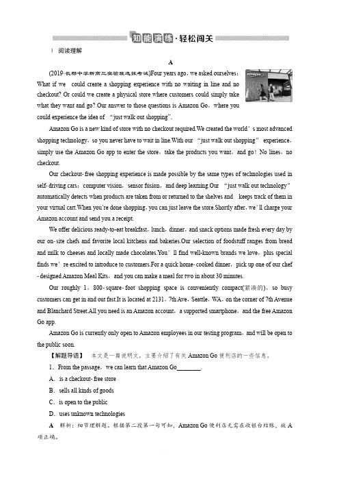
Ⅰ阅读理解A(2019·长郡中学新高三实验班选拔考试)Four years ago,we asked ourselves:What if we could create a shopping experience with no waiting in line and nocheckout? Or could we create a physical store where customers could simply takewhat they want and go? Our answer to those questions is Amazon Go,where youcould experience the idea of “just walk out shopping”.Amazon Go is a new kind of store with no checkout required.We created the world’s most advanced shopping technology,so you never have to wait in line.With our “just walk out shopping”experience,simply use the Amazon Go app to enter the store,take the products you want,and go!No lines,no checkout.Our checkoutfree shopping experience is made possible by the same types of technologies used in selfdriving cars:computer vision,sensor fusion,and deep learning.Our “just walk out technology”automatically detects when products are taken from or returned to the shelves and keeps track of them in your virtual cart.When you’re done shopping,you can just leave the store.Shortly after,we’ll charge your Amazon account and send you a receipt.We offer delicious ready-to-eat breakfast,lunch,dinner,and snack options made fresh every day by our onsite chefs and favorite local kitchens and bakeries.Our selection of foodstuff ranges from bread and milk to cheeses and locally made chocolates.You’ll find well-known brands we love,plus special finds we’re excited to introduce to customers.For a quick homecooked dinner,pick up one of our chef designed Amazon Meal Kits,and you can make a meal for two in about 30 minutes.Our roughly 1,800squarefoot shopping space is conveniently compact(紧凑的),so busy customers can get in and out fast.It is located at 2131,7th Ave,Seattle,WA,on the corner of 7th Avenue and Blanchard Street.All you need is an Amazon account,a supported smartphone,and the free Amazon Go app.Amazon Go is currently only open to Amazon employees in our testing program,and will be open to the public soon.【解题导语】本文是一篇说明文,主要介绍了有关Amazon Go便利店的一些信息。
多传感器数据融合技术综述

多传感器数据融合技术综述一、多传感器数据融合的定义数据融合技术(Multiple Sensor Information Fusion,MSIF)又称信息融合技术,它的研究起源于军事指挥智能通讯系统,即C3I (Command,Control,Communication and Intelligence)系统建设的需求,早期研究也多来自于军事方面的应用。
而随着工业系统的复杂化和智能化,该技术已被推广到民用领域,如医疗诊断、机械故障诊断、空中交通管制、遥感、智能制造、智能交通、工业智能控制及刑侦等等。
作为前沿领域技术,无论是军用系统还是民用系统,都趋向于采用数据融合技术来进行信息综合处理。
在知识爆炸的信息时代,数据融合技术就显得尤其重要,它能避免数据富有但信息贫乏的情况发生。
数据融合是关于协同利用多传感器信息,进行多级别、多方面、多层次信息检测、相关、估计和综合以获得目标的状态和特征估计以及态势和威胁评估的一种多级信息自动处理过程。
它将不同来源、不同模式、不同时间、不同地点、不同表现形式的信息进行融合,最后得出被感知对象的精确描述。
数据融合其实也就是对数据的提取和处理,得出最终的有效信息。
多传感器数据融合也就是用各种不同的传感器观测信息,然后将不同来源、不同形式、不同时间、不同地点的信息通过计算机技术,对按时间顺序获得的若干传感器的观测信息,用某种方法自动分析、综合,得到更加有效的信息。
二、国内外研究概况美国国防部JDL(Joint Directors of Laboratories)从军事应用的角度将数据融合定义为一种多层次、多方面的处理过程,即把来此许多传感器和信息源的数据和信息加以联合(Association)、相关(Correlation)和组合(Combination),以获得精确的位置估计(Position Estimation)和身份估计(Identity Estimation),以及对战情况和威胁及其重要程度进行了适时的完整评价。
自动驾驶中点云与图像多模态融合研究综述
Computer Science and Application 计算机科学与应用, 2023, 13(7), 1343-1351 Published Online July 2023 in Hans. https:///journal/csa https:///10.12677/csa.2023.137132自动驾驶中点云与图像多模态融合研究综述 孟 玥,李士心*,陈范凯,刘 宸,丛笑含天津职业技术师范大学电子工程学院,天津收稿日期:2023年6月6日;录用日期:2023年7月5日;发布日期:2023年7月12日摘要 针对复杂多变的道路环境,综合国内外研究现状,本文从激光雷达和摄像头方面论述了汽车自动驾驶中的网络输入的格式,并以两种传感器融合为例,归纳了自动驾驶汽车环境感知任务中多模态传感器融合的分类方法,在此基础上,又从融合阶段的角度总结出另一种分类,简化了融合方法的分类和理解,强调了融合程度的区别以及融合方法的整体性,这种分类对于推动融合方法的研究和发展具有创新价值。
最后分析传感器融合所遗留的问题,对未来的发展趋势进行预测。
关键词激光雷达,摄像头,多模态,传感器融合Research Review of Multimodal Fusion of Point Cloud and Image in Autonomous DrivingYue Meng, Shixin Li *, Fankai Chen, Chen Liu, Xiaohan CongCollege of Electronic Engineering, Tianjin University of Technology and Education, Tianjin Received: Jun. 6th , 2023; accepted: Jul. 5th , 2023; published: Jul. 12th , 2023AbstractIn view of the complex and changeable road environment, this paper discusses the format of net-work input in auto driving from the aspects of laser radar and camera, and summarizes the classi-fication method of multimodal sensor fusion in the environmental perception task of autonomous vehicle, based on which, another classification is summarized from the perspective of fusion stage, *通讯作者。
合成孔径声纳重叠相位中心与惯性导航系统联合估计运动误差算法

第42卷第3期兵工学报Vol.42No.3 2021年3月ACTA ARMAMENTARII Mar.2021合成孔径声纳重叠相位中心与惯性导航系统联合估计运动误差算法张羽W,王朋^2,刘纪元钟荣兴匚吊,韦琳哲^2,迟骋^2(1.中国科学院声学研究所,北京100190;2.中国科学院先进水下信息技术重点实验室,北京100190;3.中国科学院大学,北京100049)摘要:为降低运动测量系统复杂度、提高运动误差估计精度,使用回波数据与惯性导航系统(INS)数据两种数据源联合估计合成孔径声纳的运动误差,形成一种基于重叠相位中心(DPC)算法和INS的DPC联合INS算法。
利用回波的多子阵空间互相关矩阵估计声纳的前向速度,结合INS姿态角解算出DPC方法下的三向速度,采用卡尔曼滤波算法融合DPC算法的三向速度与INS 的三向加速度,输出声纳速度的最优值,从而计算运动误差。
湖试数据处理结果表明:DPC与INS 联合算法相比于传统的DPC算法,融合了INS的加速度数据,使速度曲线变得更加陡峭,增加了细节信息,提高了声纳速度估计的准确性;经过运动补偿后,图像质量得到提高,目标散焦和重影的现象均得到改善。
关键词:合成孔径声纳;运动误差;重叠相位中心;惯性导航系统;卡尔曼滤波算法中图分类号:U666.73文献标志码:A文章编号:1000-1093(2021)03-0588-10DOI:10.3969/j.issn.1000-1093.2021.03.015Motion Error Estimation Algorithm Based on DPC andINS for Synthetic Aperture SonarZHANG Yu1,2,3,WANG Peng1,2,LIU Jiyuan1,2,ZHONG Rongxing1,2,3,WEI Linzhe1,2,CHI Cheng1,2(1.Institute of Acoustics,Chinese Academy of Sciences,Beijing100190,China;2.Key Laboratory of Science and Technology on Advanced Underwater Acoustic Signal Processing,Chinese Academy of Sciences,Beijing100190,China;3.University of Chinese Academy of Sciences,Beijing100049,China)Abstract:A displaced phase center(DPC)aided inertial navigation system(INS)combination method is proposed to reduce the complexity of motion measurement system and improve the estimation accuracy of motion error of synthetic aperture sonar.A multiple-receiver spatial mutual correlation matrix is built to estimate the forward velocity of sonar in reference to DPC method,and then three-dimensional velocity can be calculated with the attitude angle from INS.Kalman filter is applied to fuse data from DPC and INS,which outputs the optimal estimation of the velocity.Finally,the motion error is calculated with the integral of the velocity.The field experimental results show that DPC aided INS combination method,in comparison to DPC algorithm,increases more motion details that the velocity curve gets sharper,which收稿日期:2020-04-13基金项目:中国科学院声学研究所青年英才计划项目(QNYC201803);中国科学院青年创新促进会项目(2019023)作者简介:张羽(1994—),男,博士研究生。
西安交大自动化专业多传感器信息融合ch1(资料)
第1章 绪论1.1多源信息融合的一般概念与定义1.1.1定义多源信息融合(multi-source information fusion)又称为多传感信息融合(multi-sensor information fusion),是20世纪70年代提出来的,军事应用是该技术诞生的源泉。
事实上,人类和自然界中其它动物对客观事物的认知过程,就是对多源信息的融合过程。
在这个认知过程中,人或动物首先通过视觉、听觉、触觉、嗅觉和味觉等多种感官(不是单纯依靠一种感官)对客观事物实施多种类、多方位的感知,从而获得大量互补和冗余的信息;然后由大脑对这些感知信息依据某种未知的规则进行组合和处理,从而得到对客观对象的统一与和谐的理解与认识。
这种由感知到认知的过程就是生物体的多源信息融合过程。
人们希望用机器来模仿这种由感知到认知的过程。
于是,一门新的边缘学科——多源信息融合便诞生了。
由于早期的融合方法研究是针对数据处理的,所以有时也把信息融合称为数据融合(data fusion)。
我们在这里所讲的传感器(sensor)也是广义的,不仅包括物理意义上的各种传感系统,也包括与观测环境匹配的各种信息获取系统,甚至包括人或动物的感知系统。
虽然人们对这门边缘学科的研究已经有20至30年的历史了,但至今仍然没有一个被普遍接受的定义。
这是因为其应用面非常广泛,而各行各业会按自己的理解给出不同的定义。
目前能被大多数研究者接受的有关信息融合的定义,是由美国三军组织实验室理事联合会JDL(Joint Directors of Laboratories)提出来的[1-3],从军事应用的角度给出信息融合的定义。
定义1.1.1 信息融合就是一种多层次、多方面的处理过程,包括对多源数据进行检测、相关、组合和估计,从而提高状态和身份估计的精度,以及对战场态势和威胁的重要程度进行适时完整的评价。
从该定义可以看出,信息融合是在几个层次上完成对多源信息处理的过程,其中每一个层次反映对原始观测数据不同级别的抽象。
(完整版)多传感器分布式航迹融合综述
多传感器航迹融合综述在20年代70年代初,R. A. Singer等人首次提出航迹融合问题,其推导了表征两航迹关联概率的“相关方程”,其实就是计算两条航迹间的玛氏距离:将关联概率小于门限值的航迹视为待融合的航迹,这即是一个假设检验问题;但其后续的航迹融合有一个隐含假设:来自同一目标、不同传感器的两个局部估计误差是相互独立的[1][2]。
[1] R. A. Singer and A. J. Kanyuck, “Computer control of multiple site track correlation”, Automatica, vol. 7, pp. 455-463, July 1971.[2] R. A. Singer and A. J. Kanyuck, “Correlation of Multiple-Site Track Data”, IEEE Transactions on Aerospace and Electronic System, vol. 6, No. 2, pp. 180-187, March 1970.而实际情况中,尽管不考虑目标机动性或量测噪声,过程噪声是相同的,因此局部估计误差往往是高度相关的,因此相关性不容忽视。
1979年,J.Speyer在多传感器分布式估计问题中将估计间的相关性考虑其中,但其不适用于假设检验问题[3]。
此外,Willsky等人也在其研究中考虑了相关性等问题[4]。
[3] J. L. Speyer, “Computation and Transmission Requirements for a Decentralized Linear- Quadratic-Gaussian Control Problem”, IEEE Transactions on Automatic Control, vol. 24 no. 2 pp. 266-269, 1979.[4] A. Willsky, M. Bello, D. Castanon, B. Levy, G. Verghese, “Combining and Updating of Local Estimates and Regional Maps Along Sets of One-Dimensional Tracks”, IEEE Transactions on Automatic Control, vol. 27, no. 4, pp. 799-813, 1982.1981年,Y. Bar-shalom等人推导了两局部估计误差互相关的简单递推公式,将互相关性融入假设统计量公式中。
机器人头部摆动机构的设计
摘要机器人足球比赛是一个多智能体系统的典型问题。
多智能体系统就是一个分布式人工智能系统,这种系统要完成的任务是出各智能体协同完成的。
在这里一个智能体是指能独立地进行决策和知识处理的系统。
机器人足球比赛的设想首先由加拿大不列颠哥伦比亚大学的A1anMackworth教授在1992年的报告《On Seeing Robots))中提出的。
举办机器人足球比赛的目的在于,通过提供一个标准任务,促使研究人员利用各种技术,获得更好的解决方案,从而有效的促进相关科研领域的发展。
机器人足球系统涉及的领域很多,包括:智能机器人系统、多智能体系统、实时图像处理与模式识别、智能结构设计、实时规划和推理、移动机器人技术、机器传动与驱动控制、传感器与数据融合和无线通讯等。
通过机器人足球比赛这一活动,为科研人员的研究活动提供标准的实验平台,在此平台的基础上,各种人工智能和机器人学等领域的研究成果可以得到检验,进而促进各学科的发展。
在世界上比较有影响的赛事主要有两个,一个是由国际人工智能协会组织的机器人世界杯足球赛RoboCup,另一个是由国际机器人足球联合会(FIRA)组织的微型机器人世界杯足球赛MiroSot。
AbstractRobot soccer game is a typical problem of multi-agent systems. Multi-agent system is a distributed artificial intelligence (ai) system, this system to complete the task is the intelligent TiXie with complete. Here refers to an intelligent body can make decisions independently and the system of knowledge processing.Robot soccer vision first by A1an at the university of British Columbia in CanadaMackworth professor in a 1992 report "On Seeing Robots)). The purpose of the robot soccer game is, by providing a standard task, prompting the researchers use a variety of technologies, get a better solution, thus effectively promote the development of related research fields. The robot soccer system involving a lot of areas, including: intelligent robot system, multi-agent system, the structure of the real-time image processing and pattern recognition, intelligent design, real-time planning and reasoning, mobile robotics, machine drive and drive control, sensor and data fusion, wireless communication and so On. Through the robot soccer game this activity, for researchers to research activities to provide a standard experimental platform, On the basis of this platform, a variety of areas such as artificial intelligence and robotics research results can be tested, thus promote the development of various disciplines.More influential events in the world in basically has two, one is organized by the international association of artificial intelligence RoboCup robot World Cup, the other one is organized by international robot football federation (FIRA) miniature MiroSot robot World Cup football match.目录1. 设计概述 (1)1.1设计课题 (1)1.2 设计总体要求 (1)1.3 原始数据 (1)1.4 机构运动简图 (1)2. 设计内容 (2)2.1 四杆机构的设计 (2)2.2 电动机的选择 (2)2.3 分配传动比 (2)2.4 蜗轮蜗杆的设计 (2)2.5大小的齿轮设计 (2)2.6 各轴的设计 (2)2.7 键连接的选择与校核计算 (2)2.8 润滑油和联轴器的选择 (2)3. 四杆机构的设计 (2)4.电动机的选择 (3)5.分配传动比 (4)6.计算传动装置的运动和动力参数 (4)6.1各轴转速 (4)6.2各轴输入功率 (4)6.3 各轴输入转矩 (4)7.蜗轮蜗杆的设计 (5)7.1选择蜗杆的传动类型 (5)7.2材料的选择 (5)7.3按齿面接触疲劳强度进行设计 (5)7.4蜗杆与蜗轮的主要参数与几何尺寸 (6)7.5校核齿根弯曲疲劳强度 (6)7.6验算效率η (6)7.7精度等级公差和表面粗糙度确定 (7)8.齿轮的设计 (7)8.1选择齿轮材料及精度等级和齿数。
传感器技术外文文献及中文翻译
Sensor technologyA sensor is a device which produces a signal in response to its detecting or measuring a property ,such as position , force ,torque ,pressure ,temperature ,humidity , speed ,acceleration , or vibration 。
Traditionally ,sensors (such as actuators and switches )have been used to set limits on the performance of machines 。
Common examples are (a)stops on machine tools to restrict work table movements ,(b)pressure and temperature gages with automatics shut—off features ,and (c) governors on engines to prevent excessive speed of operation . Sensor technology has become an important aspect of manufacturing processes and systems .It is essential for proper data acquisition and for the monitoring , communication ,and computer control of machines and systems 。
Because they convert one quantity to another ,sensors often are referred to as transducers .Analog sensors produce a signal ,such as voltage ,which is proportional to the measured quantity 。
博士生发一篇information fusion

博士生发一篇information fusion Information Fusion: Enhancing Decision-Making through the Integration of Data and KnowledgeIntroduction:Information fusion, also known as data fusion or knowledge fusion, is a rapidly evolving field in the realm of decision-making. It involves the integration and analysis of data and knowledge from various sources to generate meaningful and accurate information. In this article, we will delve into the concept of information fusion, explore its key components, discuss its application in different domains, and highlight its significance in enhancingdecision-making processes.1. What is Information Fusion?Information fusion is the process of combining data and knowledge from multiple sources to provide a comprehensive and accurate representation of reality. The goal is to overcome the limitations inherent in individual sources and derive improved insights and predictions. By assimilating diverse information,information fusion enhances situational awareness, reduces uncertainty, and enables intelligent decision-making.2. Key Components of Information Fusion:a. Data Sources: Information fusion relies on various data sources, which can include sensors, databases, social media feeds, and expert opinions. These sources provide different types of data, such as text, images, audio, and numerical measurements.b. Data Processing: Once data is collected, it needs to be processed to extract relevant features and patterns. This step involves data cleaning, transformation, normalization, and aggregation to ensure compatibility and consistency.c. Information Extraction: Extracting relevant information is a crucial step in information fusion. This includes identifying and capturing the crucial aspects of the data, filtering out noise, and transforming data into knowledge.d. Knowledge Representation: The extracted information needs to be represented in a meaningful way for integration and analysis.Common methods include ontologies, semantic networks, and knowledge graphs.e. Fusion Algorithms: To integrate the information from various sources, fusion algorithms are employed. These algorithms can be rule-based, model-based, or data-driven, and they combine multiple pieces of information to generate a unified and coherent representation.f. Decision-Making Processes: The ultimate goal of information fusion is to enhance decision-making. This requires the fusion of information with domain knowledge and decision models to generate insights, predictions, and recommendations.3. Applications of Information Fusion:a. Defense and Security: Information fusion plays a critical role in defense and security applications, where it improves intelligence analysis, surveillance, threat detection, and situational awareness. By integrating information from multiple sources, such as radars, satellites, drones, and human intelligence, it enables effective decision-making in complex and dynamic situations.b. Health Monitoring: In healthcare, information fusion is used to monitor patient health, combine data from different medical devices, and provide real-time decision support to medical professionals. By fusing data from wearables, electronic medical records, and physiological sensors, it enables early detection of health anomalies and improves patient care.c. Smart Cities: Information fusion offers enormous potential for the development of smart cities. By integrating data from multiple urban systems, such as transportation, energy, and public safety, it enables efficient resource allocation, traffic management, and emergency response. This improves the overall quality of life for citizens.d. Financial Markets: In the financial sector, information fusion helps in the analysis of large-scale and diverse datasets. By integrating data from various sources, such as stock exchanges, news feeds, and social media mentions, it enables better prediction of market trends, risk assessment, and investmentdecision-making.4. Significance of Information Fusion:a. Enhanced Decision-Making: Information fusion enables decision-makers to obtain comprehensive and accurate information, reducing uncertainty and improving the quality of decisions.b. Improved Situational Awareness: By integrating data from multiple sources, information fusion enhances situational awareness, enabling timely and informed responses to dynamic and complex situations.c. Risk Reduction: By combining information from diverse sources, information fusion improves risk assessment capabilities, enabling proactive and preventive measures.d. Resource Optimization: Information fusion facilitates the efficient utilization of resources by providing a holistic view of the environment and enabling optimization of resource allocation.Conclusion:In conclusion, information fusion is a powerful approach to enhance decision-making by integrating data and knowledge from multiple sources. Its key components, including data sources, processing, extraction, knowledge representation, fusion algorithms, and decision-making processes, together create a comprehensive framework for generating meaningful insights. By applying information fusion in various domains, such as defense, healthcare, smart cities, and financial markets, we can maximize the potential of diverse information sources to achieve improved outcomes.。
多传感器信息融合ppt课件

•定义2
利用计算机技术对按时序获得的若干传感器
的观测信息在一定准则下加以自动分析,优
化综合以完成所需的决策和估计任务而进行 的信息处理过程。实体状 态进行估计和预报的过程。������
•…….
8
自然界中同类多传感信息融合
左目和右目的视觉传感器分别 获取二维图象信息,经大脑融 合后产生立体图象信息; 左耳和右耳的听觉传感器分别 获取一维声音信息,经大脑融 合后产生立体声音信息;
1
国外研究 信息融合的关键技术 信息融合原理 信息融合层次 信息融合框架 信息融合方法 应用背景 存在的问题
2
• 信息融合 (information fusion)起初被称为数
据融合 (data fusion),起源于1973年美国国 防部资助开发的声纳信号处理系统。
• 20世纪80年代,为了满足军事领域中作战
得成效。这些领域主要包括:机器人和智能 仪器系统、智能制造系统、战场任务与无 人驾驶飞机、航天应用、目标检测与跟踪、 图像分析与理解、惯性导航、模式识别等 领域。
6
定义1(美国国防部定义:[1991] ) 信息融合是一种多层次、多方面的处理过程, 包括对多源数据进行自动化的检测、互联、 相关、估计和组合处理(automatic detection, association, correlation, estimation, and combination),从而提高状态和身份估计的 精度,以及对战场态势和威胁的重要程度进 行有效的评价。
9
自 然 界 异 类 多 传 感 信 息 融 合
10
①扩展空间和时间覆盖范围;
(利用互补信息,improve observability )
②改进探测性能;
非金属管道电阻率成像效果数值模拟研究
Open Journal of Natural Science 自然科学, 2023, 11(5), 753-759 Published Online September 2023 in Hans. https:///journal/ojns https:///10.12677/ojns.2023.115090非金属管道电阻率成像效果数值模拟研究穆路谦,曹志鹏,黄思俊,陈宝佳,王明明宿州学院资源与土木工程学院,安徽 宿州收稿日期:2023年6月25日;录用日期:2023年8月21日;发布日期:2023年8月28日摘要非金属管道被广泛用于城市地下管线中,是城市基础设施的重要组成部分,但非金属管道具有非导电导磁和绝缘性,在管线探测中是一个难题。
本文采用数值模拟方法,对不同间距、不同直径、不同埋深的非金属管道的电阻率成像特点进行数值模拟研究。
结果表明:当两根非金属管道横向排列间距较大时,电阻率成像能够清晰分辨两管道位置,但随着管道间距变小,电阻率成像难以对两根管道进行区分。
两根较粗管道,对应两管道位置出现高阻异常区,两高阻异常区相连通,在两管道中间下方出现下凸的高阻异常,对应两管道的中间位置。
当两管道纵向排列时,上下两根管道形成一个异常区,电阻率成像难以在垂向上区分两根管道。
关键词非金属管道,电阻率成像,数值模拟,不同间距,不同直径,不同埋深Numerical Simulation Study on the Imaging Effect of Non-Metallic Pipeline ResistivityLuqian Mu, Zhipeng Cao, Sijun Huang, Baojia Chen, Mingming WangSchool of Resources and Civil Engineering, Suzhou University, Suzhou AnhuiReceived: Jun. 25th , 2023; accepted: Aug. 21st , 2023; published: Aug. 28th, 2023AbstractNon metallic pipelines are widely used in urban underground pipelines and are an important component of urban infrastructure. However, non-metallic pipelines have non-conductive, mag-netic, and insulating properties, making them a challenge in pipeline detection. This paper uses numerical simulation methods to study the electrical resistivity imaging characteristics of non- metallic pipelines with different spacing, diameter, and burial depth. The results indicate that when the horizontal spacing between two non-metallic pipelines is large, resistivity imaging can穆路谦等clearly distinguish the positions of the two pipelines, but as the spacing between pipelines de-creases, resistivity imaging is difficult to distinguish between the two pipelines. Two thicker pipe-lines have high resistance abnormal areas corresponding to the positions of the two pipelines. The two high resistance abnormal areas are connected, and a convex high resistance abnormal area appears below the middle of the two pipelines, corresponding to the middle position of the two pipelines. When two pipelines are arranged vertically, the upper and lower pipelines form an ab-normal area, making it difficult for resistivity imaging to distinguish the two pipelines vertically.KeywordsNon Metallic Pipelines, Resistivity Imaging, Numerical Simulation, Different Spacing, DifferentDiameters, Different Burial Depths Array Copyright © 2023 by author(s) and Hans Publishers Inc.This work is licensed under the Creative Commons Attribution International License (CC BY 4.0)./licenses/by/4.0/1. 引言地下管道如同人体血管贯穿整个城市,是城市基础设施的重要组成部分,对城市的发展至关重要[1][2][3]。
英语-陌生单词I

Sometimes, even if you know all the individual words in a presence, the presence structure can be so complex that it's difficult to understand the meaning
Read the presence or paragraph containing the unknown word
Try to infer the meaning of the word based on the context and your knowledge of English grammar and vocabulary
Use a dictionary or online resources to confirm your presence and learn the correct meaning of the word
04
The application of unfriendly words
Usage in spoke language
association between the two
Visualization
03
Imagine a visual representation of the word or its
meaning to help you remember it
Guessing word meanings through context
Precision in communication
Using specific vocabulary can help to communicate ideas more accurately, reducing the potential for misunderstandings or fusion
- 1、下载文档前请自行甄别文档内容的完整性,平台不提供额外的编辑、内容补充、找答案等附加服务。
- 2、"仅部分预览"的文档,不可在线预览部分如存在完整性等问题,可反馈申请退款(可完整预览的文档不适用该条件!)。
- 3、如文档侵犯您的权益,请联系客服反馈,我们会尽快为您处理(人工客服工作时间:9:00-18:30)。
SENSOR FUSION UNDER UNKNOWN ASSOCIATIONS BY PARTICLE FILTERS WITH CLEVER PROPOSALNorikazu Ikoma,Wataru Ito,Masato Kawanishi,and Hiroshi Maeda Faculty of Engineering,Kyushu Institute of Technology,Fukuoka804-8550,JAPANEmail:ikoma@comp.kyutech.ac.jpABSTRACTA new method for sensor fusion under unknown as-sociations among multiple sensors is proposed.Fun-damental problem within the sensor fusion situation ishuge number of the associations that prohibits to enu-merate all the combinations within tractable computa-tional time.Proposed method formulates this situationin a state space model,which is highly nonlinear todeal with the unknown associations,and utilizes par-ticlefilters to estimate state of the model.Then weobtain state of the target system as well as the asso-ciations through the state estimation.We also proposeclever proposal in the framework of particlefilters thatdraws efficient particles in a sense of sub-optimalityto minimize the variance of particles’weight.The pro-posed method is formulated in generic way,so,in prin-ciple,it can be applied to various situations for sensorfusion under unknown associations.We show an illus-trative example to track sound target in a scene withsensors of two microphones and one camera.Keywords:Sensor fusion,state space model,particlefilter,nonlinear,clever proposal,target tracking.1.INTRODUCTIONSensor fusion can be defined as a task that reconstructsreal world information by using data coming from mul-tiple sensors where it is difficult or impossible to ob-tain the information by using only single sensor.Mosthighly organized life,including human,perform thistask naturally.Also there are many examples of thistask in engineeringfield,such as3D reconstruction incomputer vision,target detection using multiple sen-sors(e.g.,radar,sonar,and infrared rays),and recogni-tion of environment(e.g.,localization,object recogni-tion,and map learning)by mobile robot with multiplesensors’data.Fundamental problem arises in sensor fusion,whichis called association problem.The problem is to deter-mine the unknown correspondence among signals ofall sensors.Here it is assumed that the sensor gener-ally detects many signals of the real world objects andcorrespondence between the signals and the objects isunknown.Then the problem is equivalent to determinethe correspondence between the signals of a sensor andthe objects,for all sensors.This causes a combinato-rial problem,which is factorial order of the number2.MODELWe propose a new state space model for sensor fusion under unknown associations.The state space model consists of system equation and observation equation. System equation represents dynamics of the target sys-tem,and observation equation is a set of equations for all sensors.System equation is(1) where is state of target system at discrete time. The state contains information about objects in the target system.is i.i.d.random vector having pdf ,and it is called”system noise”.Suppose that there are sensors,and letbe index variable for the sensors.-th sensor model is represented by(2) where is vector of signals detected by-th sensor, and is i.i.d.random vector having pdf,and it is called”observation noise”.All noises appeared above,i.e.,and for,are assumed to be mutually independent. Suppose that has signals,which is con-sisting of signals coming from the target sys-tem and signals due to false detection.Thusand it follows that.is associations vector having elements as(3)Each element takes value in,where means the signal is false detection,and other values, ,means-th signal comes from-th object in the target system.Let be combination number of the associ-ations of-th sensor.Then,combination number for all sensors becomes.For example,if there is no false detection and missing,and one to one mapping between objects in the target system and de-tected signals holds,then,.The num-ber becomes much larger for more realistic situations with false detection and missing.We assume Markov property for time evolution of the associations,such that,where.For example,we can assume that the associations,,are mutually inde-pendent with respect to the sensors,and association of each sensor,,is assumed to be of Markov process with high probability to stay the same state and with small probability to change the state.We augment the state vector as.By denoting,we can form an augmented state space model such that(4)(5)with appropriate definitions for system noise vector and observation noise vector.By estimating the augmented state of the state space model(4)and(5),we can obtain the estimation of state of the target system,,and the associations,,si-multaneously.3.PARTICLE FILTERS3.1.Simple Particle FilterFor the state estimation,we use”particlefilters”[3]. Particlefilters use many number of weighted parti-cles in the state space to approximate target distribu-tion.The target distribution is conditional distribu-tion of the state given a series of observation such that,where we employ useful notation.Particlefilters update the conditional distribution,i.e.,it is recursive estimation such thatDraw particles from”proposal distribution”,which is denoted by,such that(7) 2)Weight update:(8) note that is normalized.Now,we let,then we have set of weighted par-ticles,,as an approximation of .3)Re-sampling:,then we have as an-other approximation of.3.2.Rao-Blackwellized Particle FilterTo have efficient performance of particlefilters,we further introduce an elaborated idea called”Rao-Blackwellization(RB)”[1],which decomposes the state into analytical part and particle approximation part as(9) where is approximated by weighted par-ticles,and is calculated based on Kalmanfilter.Through the same derivation of eq.(6),we haveDraw particles,i.e.associations,from proposal as,(11) 2)Kalman update(RB):For,update weight by In RB,we sample particles with analytical part,i.e.,mean vector and covariance ma-trix.So we perform resampling fromin similar way as simple particlefilter.3.3.Clever ProposalHere is a choice of the proposal distribution.It is a key to make particlefilters be efficient.The optimal proposal has been proposed in the literatures asFig.1.Image sequence.y [p i x e l ]x[pixel]Fig.2.Tracking result of sound target.4.EXAMPLEAs an example of sensor fusion,we demonstrate soundtarget tracking using one camera and two microphones with a scene peoples are in motion.Some frames of the captured image sequence are shown in Fig.1,where a man,right hand side,makes sound by clapping his hand,and the other is moving without sound.For each frame of the image sequence,feature points are extracted by corner detector based on a local fea-ture of the image as plotted in Fig.1.From recorded sound by the two microphones,we calculate direction of sound as plotted in Fig.3.By applying the proposed method,we have esti-mated state of the sound target,which consists of posi-tion of each feature point and velocity of the target ob-ject.Estimated result of positions are shown in Fig.2with observed data,positions of feature points.By looking at the result,we can see that smooth trajectory of the sound target is obtained.Estimated result of the association is as follows.Be-ginning part of the image frames starting from the time when first sound signal occurred is shown in table 1.In this result,all associations are correctly estimated within the table,and mostly correct throughout the im-age frames.5.CONCLUSIONWe have proposed a general model for sensor fusion in a form of nonlinear state space model having unknownx [p i x e l ]time[frame]Fig.3.Sound direction.Table 1.Estimated associations.feature points’associations70012309012300110123000013001200015123。
