UB500-18GM75-U-V15中文
CommScope 优灵-U 低损耗 OM5 双面双通道光纤连接器说明书
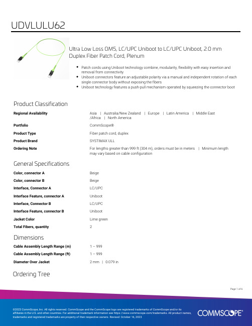
Ultra Low Loss OM5, LC/UPC Uniboot to LC/UPC Uniboot, 2.0 mmDuplex Fiber Patch Cord, PlenumPatch cords using Uniboot technology combine, modularity, flexibility with easy insertion andremoval from connectivityUniboot connectors feature an adjustable polarity via a manual and independent rotation of eachsingle connector body without exposing the fibersUniboot technology features a push-pull mechanism operated by squeezing the connector bootProduct ClassificationRegional Availability Asia | Australia/New Zealand | Europe | Latin America | Middle East/Africa | North AmericaPortfolio CommScope®Product Type Fiber patch cord, duplexProduct Brand SYSTIMAX ULLOrdering Note For lengths greater than 999 ft (304 m), orders must be in meters | Minimum lengthmay vary based on cable configurationGeneral SpecificationsColor, connector A BeigeColor, connector B BeigeInterface, Connector A LC/UPCInterface Feature, connector A UnibootInterface, Connector B LC/UPCInterface Feature, connector B UnibootJacket Color Lime greenTotal Fibers, quantity2DimensionsCable Assembly Length Range (m) 1 – 999Cable Assembly Length Range (ft) 1 – 999Diameter Over Jacket 2 mm | 0.079 inOrdering Tree16Page ofMechanical SpecificationsCable Retention Strength, maximum11.24 lb @ 0 ° | 4.40 lb @ 90 °Optical SpecificationsFiber Mode MultimodeFiber Type OM5, LazrSPEED®Insertion Loss, maximum0.15 dBReturn Loss, minimum35 dBEnvironmental SpecificationsOperating Temperature-10 °C to +60 °C (+14 °F to +140 °F)Environmental Space PlenumRegulatory Compliance/CertificationsAgency ClassificationCHINA-ROHS Above maximum concentration valueISO 9001:2015Designed, manufactured and/or distributed under this quality management system ROHS Compliant/ExemptedUK-ROHSCompliant/ExemptedIncluded Products760251109P-002-MP-5G-F20LM/LTS–Fiber indoor cable, LazrSPEED® Plenum Light Duty Interconnect Cordage, 2 fiber, MultimodeOM5, Feet jacket marking, Lime green jacket color860658162– 2.0 mm LC Uniboot GEN 1.5, Lime GreenPage of26Page of 36Fiber indoor cable, LazrSPEED® Plenum Light Duty InterconnectCordage, 2 fiber, Multimode OM5, Feet jacket marking, Lime green jacket colorProduct ClassificationRegional AvailabilityAsia | Australia/New Zealand | Latin America | Middle East/Africa | North America PortfolioCommScope®Product TypeFiber indoor cable Product Series P-MPGeneral SpecificationsCable TypeMPO trunk cable Construction TypeNon-armored Subunit TypeGel-free Jacket ColorLime green Jacket MarkingFeet Total Fiber Count 2DimensionsDiameter Over Jacket 2 mm | 0.079 inRepresentative ImageMechanical SpecificationsMinimum Bend Radius, loaded38 mm | 1.496 inMinimum Bend Radius, unloaded16 mm | 0.63 inTensile Load, long term, maximum20 N | 4.496 lbfTensile Load, short term, maximum67 N | 15.062 lbfCompression 4 N/mm | 22.841 lb/inCompression Test Method FOTP-41 | IEC 60794-1 E3Flex300 cyclesFlex Test Method FOTP-104 | IEC 60794-1 E6Impact0.74 N-m | 6.55 in lbImpact Test Method FOTP-25 | IEC 60794-1 E4Strain See long and short term tensile loadsStrain Test Method FOTP-33 | IEC 60794-1 E1Twist10 cyclesTwist Test Method FOTP-85 | IEC 60794-1 E7Vertical Rise, maximum500 m | 1,640.42 ftOptical SpecificationsFiber Type OM5, LazrSPEED® wideband | OM5, LazrSPEED® widebandEnvironmental SpecificationsInstallation temperature0 °C to +70 °C (+32 °F to +158 °F)Operating Temperature0 °C to +70 °C (+32 °F to +158 °F)Storage Temperature-40 °C to +70 °C (-40 °F to +158 °F)Cable Qualification Standards ANSI/ICEA S-83-596 | Telcordia GR-409Environmental Space PlenumFlame Test Listing NEC OFNP (ETL) and c(ETL)Flame Test Method NFPA 130 | NFPA 262Environmental Test SpecificationsHeat Age0 °C to +85 °C (+32 °F to +185 °F)Heat Age Test Method IEC 60794-1 F9Low High Bend0 °C to +70 °C (+32 °F to +158 °F)46Page ofLow High Bend Test Method FOTP-37 | IEC 60794-1 E11Temperature Cycle0 °C to +70 °C (+32 °F to +158 °F)Temperature Cycle Test Method FOTP-3 | IEC 60794-1 F1Packaging and WeightsCable weight 3.2 kg/km | 2.15 lb/kft* FootnotesOperating Temperature Specification applicable to non-terminated bulk fiber cable56Page of860658162Page of 662.0 mm LC Uniboot GEN 1.5, Lime GreenProduct ClassificationRegional AvailabilityAsia | Australia/New Zealand | EMEA | Latin America | North America Product Type Fiber connector bootGeneral SpecificationsColor Lime greenDimensionsCompatible Cable Diameter 2 mm | 0.079 inPackaging and WeightsPackaging Type BagRegulatory Compliance/CertificationsAgencyClassification CHINA-ROHSBelow maximum concentration value REACH-SVHCCompliant as per SVHC revision on /ProductCompliance ROHSCompliant UK-ROHSCompliant。
必威自动化Profibus网关配置相互模块到STEP7详细地址分配
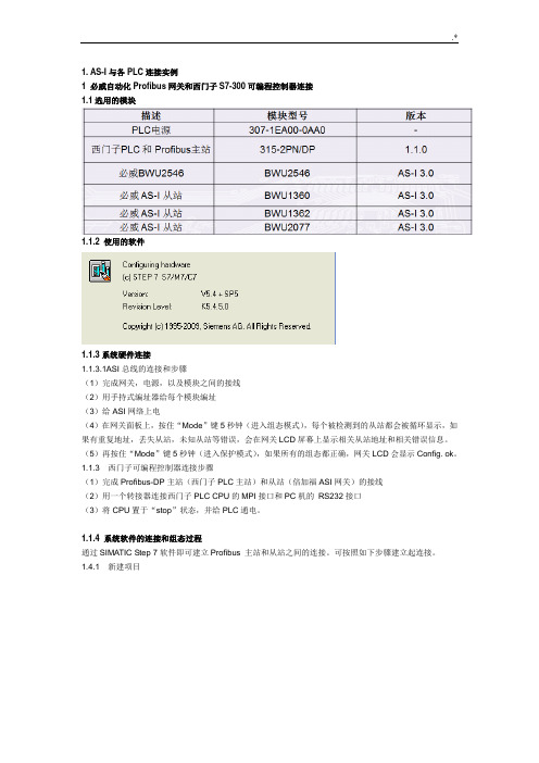
1. AS-I与各PLC连接实例1 必威自动化Profibus网关和西门子S7-300可编程控制器连接1.1选用的模块1.1.2 使用的软件1.1.3系统硬件连接1.1.3.1ASI总线的连接和步骤(1)完成网关,电源,以及模块之间的接线(2)用手持式编址器给每个模块编址(3)给ASI网络上电(4)在网关面板上,按住“Mode”键5秒钟(进入组态模式),每个被检测到的从站都会被循环显示,如果有重复地址,丢失从站,未知从站等错误,会在网关LCD屏幕上显示相关从站地址和相关错误信息。
(5)再按住“Mode”键5秒钟(进入保护模式),如果所有的组态都正确,网关LCD会显示Config. ok。
1.1.3 西门子可编程控制器连接步骤(1)完成Profibus-DP主站(西门子PLC主站)和从站(倍加福ASI网关)的接线(2)用一个转接器连接西门子PLC CPU的MPI接口和PC机的RS232接口(3)将CPU置于“stop”状态,并给PLC通电。
1.1.4 系统软件的连接和组态过程通过SIMATIC Step 7软件即可建立Profibus 主站和从站之间的连接。
可按照如下步骤建立起连接。
1.4.1 新建项目从主菜单中选择文件菜单,再选择新建。
写入你想要创建项目的名字,并选择存储位置。
1.4在项目中组态站点从主菜单中选择插入菜单,然后选择300站点。
左键点击SIMATIC 300(1) 再双击Hardware 图标。
先为PLC添加导轨,再按照前面列出的硬件型号,从硬件列表中选择所使用的西门子产品,依次添加PLC的电源和CPU。
1.1.4.3 Profibus 网络组态添加PLC的CPU之后,会弹出一个属性窗口,设置DP口的参数建立新的网络并选择1.5Mbps 速率,这个波特率对于CPU运行来说完全足够用。
安装网关的电子数据库(GSD)文件并刷新列表。
将列表中所使用的网关拖入DP主站的黑线上,这时的ASI网关就成为Profibus总线上的DP从站。
必威自动化Profibus网关配置相关模块到STEP 7_详细地址分配
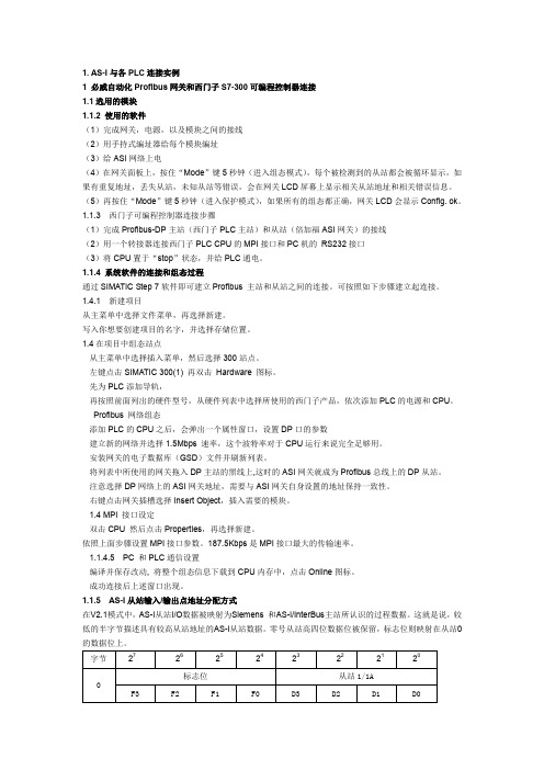
1. AS-I与各PLC连接实例1 必威自动化Profibus网关和西门子S7-300可编程控制器连接1.1选用的模块1.1.2 使用的软件(1)完成网关,电源,以及模块之间的接线(2)用手持式编址器给每个模块编址(3)给ASI网络上电(4)在网关面板上,按住“Mode”键5秒钟(进入组态模式),每个被检测到的从站都会被循环显示,如果有重复地址,丢失从站,未知从站等错误,会在网关LCD屏幕上显示相关从站地址和相关错误信息。
(5)再按住“Mode”键5秒钟(进入保护模式),如果所有的组态都正确,网关LCD会显示Config. ok。
1.1.3 西门子可编程控制器连接步骤(1)完成Profibus-DP主站(西门子PLC主站)和从站(倍加福ASI网关)的接线(2)用一个转接器连接西门子PLC CPU的MPI接口和PC机的RS232接口(3)将CPU置于“stop”状态,并给PLC通电。
1.1.4 系统软件的连接和组态过程通过SIMATIC Step 7软件即可建立Profibus 主站和从站之间的连接。
可按照如下步骤建立起连接。
1.4.1 新建项目从主菜单中选择文件菜单,再选择新建。
写入你想要创建项目的名字,并选择存储位置。
1.4在项目中组态站点从主菜单中选择插入菜单,然后选择300站点。
左键点击SIMATIC 300(1) 再双击Hardware 图标。
先为PLC添加导轨,再按照前面列出的硬件型号,从硬件列表中选择所使用的西门子产品,依次添加PLC的电源和CPU。
Profibus 网络组态添加PLC的CPU之后,会弹出一个属性窗口,设置DP口的参数建立新的网络并选择1.5Mbps 速率,这个波特率对于CPU运行来说完全足够用。
安装网关的电子数据库(GSD)文件并刷新列表。
将列表中所使用的网关拖入DP主站的黑线上,这时的ASI网关就成为Profibus总线上的DP从站。
注意选择DP网络上的ASI网关地址,需要与ASI网关自身设置的地址保持一致性。
UB系列独立控制器操作手册

2ห้องสมุดไป่ตู้
3.2.3 模式修改限制功能 ............................................................................................................. 18 3.2.4 多温度传感器设置 ............................................................................................................. 19 3.2.5 温度传感器类型选择 ......................................................................................................... 19 3.2.6 UI 输入补偿功能................................................................................................................ 19 3.2.7 报警输入类型选择............................................................................................................. 20 3.2.8 模拟输出范围选择............................................................................................................. 20 3.2.9 数字输出类型选择............................................................................................................. 20 3.2.10 常规低温保护功能的设置 ............................................................................................... 21 3.2.11 除湿与制冷优先级选择.................................................................................................. 21 本功能仅型号 UB2221CH/EN 和 UB4334SCH/EN 适用 ......................................................... 21 3.3 特殊情况处理 ............................................................................................................................ 21 3.3.1 传感器异常处理................................................................................................................. 21 3.3.2 报警输入处理..................................................................................................................... 21 3.3.3 冬季模式与夏季模式......................................................................................................... 22 3.3.4 运行与待机......................................................................................................................... 22 3.4 典型控制说明 ............................................................................................................................ 23 3.4.1 PID 加热/制冷,加湿/除湿控制 ....................................................................................... 23 3.4.2 单(多)级加热/制冷控制 ................................................................................................ 23 3.4.3 单(多)级辅助输出控制................................................................................................. 23 附录一:配置项代码及配置参数说明表 .......................................................................................... 24 UB1211CH/EN................................................................................................................................. 24 UB2204CH/EN................................................................................................................................. 27 UB2221CH/EN................................................................................................................................. 31 UB4334SCH/EN .............................................................................................................................. 37 附录二:应用程序举例 ...................................................................................................................... 47
u500 产品说明书
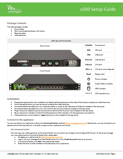
Package ContentsThe u500 package includes:●Power cable●Rack mounting bracket ears with screws ●Ethernet cable ●u500 applianceu500 rear and front panelsRear PanelFront PanelConsole Console port VGAVGA port USB USB ports ExternalInternet port InternalLAN portEth2 - 6LAN port (not configured) ResetReset switch Power indicatorSystem status indicator HDD indicatorLCD keypad arrowsInstallation●Prepare the appliance for rack installation by fastening the bracket ears to the sides of the chassis using the provided hardware. ●Mount the appliance to your rack enclosure using the provided hardware.●Connect the ethernet cable from your Internet modem or router to the Internet port (External) located on the rear panel. ●Connect the ethernet cable from your LAN switch to the LAN port (Internal) located on the rear panel. ●Plug in the power cable to a power source and connect it to the AC power input located on the rear panel. ●Review the power indicator on the front of the appliance. If the indicator is lit, the appliance is powered on. ●If the appliance is not powered on, toggle the power switch located on the rear panel.Connect to the applianceYou can connect to your appliance via the online C ommand Center portal at h ttps:///cmd . Alternatively, you can connect to your appliance from the local network, or directly using a monitor, keyboard, and mouse.Via Command CenterProvisioning a new u500 appliance via Command Center is a convenient way to deploy and configure NG Firewall. To set up and manage your new appliance from Command Center follow these steps:1.Navigate your web browser to h ttps:///cmd .2.Log in with your Untangle Command Center account, or click C reate Account to set up an account.3.In Command Center, click A dd in the Appliances screen.4.Enter the serial number located on the side panel of your appliance.5.Click A dd to confirm the new appliance.6.After the appliance successfully adds to your account, you can select it from the list of appliances.7.Click R emote Access to connect to the administration of your new appliance.8.Continue to the setup wizard.Via network connectionAlternatively, you can connect to your NG Firewall management interface from the local area network. This is useful for example if your NG Firewall appliance cannot reach the Internet and you require local administration to configure the TCP/IP settings. To access theadministration from a local network follow these steps:1.Connect your management system to the network attached to the LAN port (Internal) of the appliance.2.Check the network status of your management system and confirm that you receive an IPv4 address in the subnet of192.168.2.0/24 (e.g. 192.168.2.100).3.In a browser, navigate to 192.168.2.1.4.Accept the SSL certificate notice in your browser and continue to the setup wizard.Via direct connectionIf neither of the previous options is available, you can connect to your appliance directly by attaching a display to the VGA port and a keyboard and mouse to any of the USB ports. At the menu on the bottom of the screen, click L aunch Client to open the administration in a browser and continue to the setup wizard.Configure the setup wizardWhen you connect to the administration for the first time, the setup wizard prompts you to configure the essential parameters to get your appliance up and running.Get StartedNG Firewall packages its premium features as apps. During your first login NG Firewall prompts you to install the recommended apps. If you do not have a license, some of the recommended apps run as a 14 day trial. The trial converts to a subscription once you apply a valid license. You can learn more about NG Firewall apps at h ttps:///untangle-ng-firewall/applications/.WarrantyThis appliance is covered by a one, two or three year manufacturer warranty based on the option chosen at the time of purchase. For a description of the warranty policy visit h ttp:///refund-return-policy.Support & DocumentationFor technical support availability, contact information, and troubleshooting tips visit h ttp://. Help resources are available in the online help system at h ttp://.。
必威自动化Profibus网关配置相关模块到STEP详细地址分配
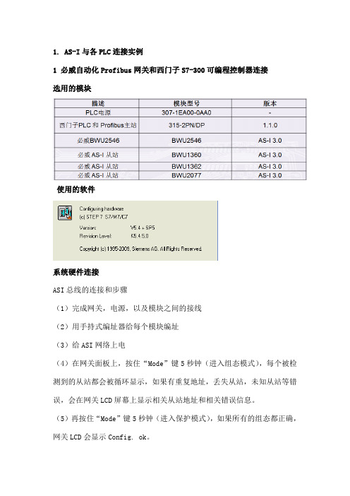
1. AS-I与各PLC连接实例1 必威自动化Profibus网关和西门子S7-300可编程控制器连接选用的模块使用的软件系统硬件连接ASI总线的连接和步骤(1)完成网关,电源,以及模块之间的接线(2)用手持式编址器给每个模块编址(3)给ASI网络上电(4)在网关面板上,按住“Mode”键5秒钟(进入组态模式),每个被检测到的从站都会被循环显示,如果有重复地址,丢失从站,未知从站等错误,会在网关LCD屏幕上显示相关从站地址和相关错误信息。
(5)再按住“Mode”键5秒钟(进入保护模式),如果所有的组态都正确,网关LCD会显示Config. ok。
西门子可编程控制器连接步骤(1)完成Profibus-DP主站(西门子PLC主站)和从站(倍加福ASI网关)的接线(2)用一个转接器连接西门子PLC CPU的MPI接口和PC机的 RS232接口(3)将CPU置于“stop”状态,并给PLC通电。
系统软件的连接和组态过程通过SIMATIC Step 7软件即可建立Profibus 主站和从站之间的连接。
可按照如下步骤建立起连接。
新建项目从主菜单中选择文件菜单,再选择新建。
写入你想要创建项目的名字,并选择存储位置。
在项目中组态站点从主菜单中选择插入菜单,然后选择300站点。
左键点击SIMATIC 300(1) 再双击 Hardware 图标。
先为PLC添加导轨,再按照前面列出的硬件型号,从硬件列表中选择所使用的西门子产品,依次添加PLC的电源和CPU。
Profibus 网络组态添加PLC的CPU之后,会弹出一个属性窗口,设置DP口的参数建立新的网络并选择速率,这个波特率对于CPU运行来说完全足够用。
安装网关的电子数据库(GSD)文件并刷新列表。
将列表中所使用的网关拖入DP主站的黑线上,这时的ASI网关就成为Profibus总线上的DP从站。
注意选择DP网络上的ASI网关地址,需要与ASI网关自身设置的地址保持一致性。
UB1000-18GM75-I-V15

Singapore: +65 6779 9091 fa-info@
Copyright Pepperl+Fuchs China: +86 21 6630 3939 fa-info@
超声波接近开关
调节声锥特性 超声波接近开关有两种不同的声锥形状可选:宽声锥和窄声锥。
V15 থഗ
2 3 4 1 5
材料 外壳 换能器 重量
Subject to modifications without notice Pepperl+Fuchs Group Germany: +49 621 776-4411 fa-info@
Release date: releasedate Date of issue: 2009-09-09 204535_CN.xml
Subject to modifications without notice Pepperl+Fuchs Group Germany: +49 621 776-4411 fa-info@
UB1000-18GM75-I-V15
1. 窄声锥 - 切断电源 - 把 TEACH-IN 输入端连接 -UB - 接通电源 - 红色的 LED 灯会每隔一段时间闪烁一次 - 黄色 LED 灯一直亮:表示有物体存在或者在检测区域内有干扰的物体 - 断开 TEACH-IN 输入端与 -UB 的连接,设置被保存 2. 宽声锥 - 切断电源 - 把 TEACH-IN 输入端连接 +UB - 接通电源 - 红色的 LED 灯会每隔一段时间闪烁两次 - 黄色 LED 灯一直亮:表示有物体存在或者在检测区域内有干扰的物体 - 断开 TEACH-IN 输入端与 +UB 的连接,设置被保存
NUC微控制器产品系列说明书

M251 Feature
。 Arm® Cortex®-M23 。 运行速度可达 48 MHz
M252 Feature
。 USB 2.0 全速设备无需外 挂晶振
M253 Feature
。 USB 2.0 全速设备无需外 挂晶振
。 高达五路 UART 。 CAN FD x1
2
Low Power
TrustZone
AEC-Q100
Market Trend
随着电子应用对低功耗或电池供电的需 求日益增加,现今的应用必须尽量降低 能源消耗,甚至在极端情况下,可能需 要倚赖单颗电池来维持长达 15 至 20 年 运转
低功耗应用情景包含手持式设备、居家、 AIoT、IIoT (工业物联网) 等应用情景, 使用范围十分广泛
(Programmable Serial I/O) • USB 2.0 全速装置无需外挂晶振 • 独立的 RTC 电源 VBAT 管脚
Highlight
• 支持 1.8 V ~ 5.5 V 串行接口,可连接不同电压 装置
*USCI: Universal Serial Control Interface Controller
C
1.8 3.3 5 M253
CU
3.3 5 M071
1.8 3.3 5 M252
U
3.3 5 M051
1.8 3.3 5 M251
3.3 5 Mini51
3.3 5 3.3 5
1.8 3.3 Nano100
M480 M460 M471 M453 M452 M451
E CU E CU
U C
U
Arm9™
必威自动化Profibus网关配置相关模块到STEP 7_详细地址分配

1. AS-I与各PLC连接实例1 必威自动化Profibus网关和西门子S7-300可编程控制器连接1.1选用的模块1.1.2 使用的软件1.1.3系统硬件连接1.1.3.1ASI总线的连接和步骤(1)完成网关,电源,以及模块之间的接线(2)用手持式编址器给每个模块编址(3)给ASI网络上电(4)在网关面板上,按住“Mode”键5秒钟(进入组态模式),每个被检测到的从站都会被循环显示,如果有重复地址,丢失从站,未知从站等错误,会在网关LCD屏幕上显示相关从站地址和相关错误信息。
(5)再按住“Mode”键5秒钟(进入保护模式),如果所有的组态都正确,网关LCD会显示Config. ok。
1.1.3 西门子可编程控制器连接步骤(1)完成Profibus-DP主站(西门子PLC主站)和从站(倍加福ASI网关)的接线(2)用一个转接器连接西门子PLC CPU的MPI接口和PC机的RS232接口(3)将CPU置于“stop”状态,并给PLC通电。
1.1.4 系统软件的连接和组态过程通过SIMATIC Step 7软件即可建立Profibus 主站和从站之间的连接。
可按照如下步骤建立起连接。
1.4.1 新建项目从主菜单中选择文件菜单,再选择新建。
写入你想要创建项目的名字,并选择存储位置。
1.4在项目中组态站点从主菜单中选择插入菜单,然后选择300站点。
左键点击SIMATIC 300(1) 再双击Hardware 图标。
先为PLC添加导轨,再按照前面列出的硬件型号,从硬件列表中选择所使用的西门子产品,依次添加PLC的电源和CPU。
1.1.4.3 Profibus 网络组态添加PLC的CPU之后,会弹出一个属性窗口,设置DP口的参数建立新的网络并选择1.5Mbps 速率,这个波特率对于CPU运行来说完全足够用。
安装网关的电子数据库(GSD)文件并刷新列表。
将列表中所使用的网关拖入DP主站的黑线上,这时的ASI网关就成为Profibus总线上的DP从站。
优普路UB510直流无刷电机驱动器(BLDC Controller)说明书

BLDC Controller 直流无刷电机驱动器(UB510)使用手册感谢您使用本产品,本使用操作手册提供UB510驱动器的配置、调试、控制相关信息。
内容包括。
l驱动器和电机的安装与检查l试转操作步骤l驱动器控制功能介绍及调整方法l检测与保养l异常排除本使用操作手册适合下列使用者参考l安装或配线人员l试转调机人员l维护或检查人员在使用之前,请您仔细详读本手册以确保使用上的正确。
此外,请将它妥善放置在安全的地点以便随时查阅。
下列在您尚未读完本手册时,请务必遵守事项: l安装的环境必须没有水气,腐蚀性气体及可燃性气体l接线时禁止将电源接至电机 U、V、W 的接头,一旦接错时将损坏驱动器 l在通电时,请勿拆解驱动器、电机或更改配线l在通电运作前,请确定紧急停机装置是否随时启动l在通电运作时,请勿接触散热片,以免烫伤警告:驱动器用于通用工业设备。
要注意下列事项:(1).为了确保正确操作,在安装、接线和操作之前必须通读操作说明书。
(2).勿改造产品。
(3).当在下列情况下使用本产品时,应该采取有关操作、维护和管理的相关措施。
在这种情况下,请与我们联系。
①用于与生命相关的医疗器械。
②用于可能造成人身安全的设备,例如:火车或升降机。
③用于可能造成社会影响的计算机系统④用于有关对人身安全或对公共设施有影响的其他设备。
(4).对用于易受震动的环境,例如:交通工具上操作,请咨询我们。
(5).如未按上述要求操作,造成直接或间接损失,我司将不承担相关责任。
如果您在使用上仍有问题,请咨询优普路客服技术支持中心1概述本公司研发生产的BLDC驱动器是一款高性能,多功能,低成本的带霍尔传感器直流无刷驱动器。
全数字式设计使其拥有灵活多样的输入控制方式,极高的调速比,低噪声,完善的软硬件保护功能,驱动器可通过串口通信接口与计算机相连,实现PID参数调整,保护参数,电机参数,加减速时间等参数的设置,还可进行IO输入状态,模拟量输入,告警状态及母线电压的监视。
必威自动化Profibus网关配置相关模块到STEP 7_详细地址分配

1. AS-I与各PLC连接实例1 必威自动化Profibus网关和西门子S7-300可编程控制器连接1.1选用的模块1.1.2 使用的软件1.1.3系统硬件连接1.1.3.1ASI总线的连接和步骤(1)完成网关,电源,以及模块之间的接线(2)用手持式编址器给每个模块编址(3)给ASI网络上电(4)在网关面板上,按住“Mode”键5秒钟(进入组态模式),每个被检测到的从站都会被循环显示,如果有重复地址,丢失从站,未知从站等错误,会在网关LCD屏幕上显示相关从站地址和相关错误信息。
(5)再按住“Mode”键5秒钟(进入保护模式),如果所有的组态都正确,网关LCD会显示Config. ok。
1.1.3 西门子可编程控制器连接步骤(1)完成Profibus-DP主站(西门子PLC主站)和从站(倍加福ASI网关)的接线(2)用一个转接器连接西门子PLC CPU的MPI接口和PC机的RS232接口(3)将CPU置于“stop”状态,并给PLC通电。
1.1.4 系统软件的连接和组态过程通过SIMATIC Step 7软件即可建立Profibus 主站和从站之间的连接。
可按照如下步骤建立起连接。
1.4.1 新建项目从主菜单中选择文件菜单,再选择新建。
写入你想要创建项目的名字,并选择存储位置。
1.4在项目中组态站点从主菜单中选择插入菜单,然后选择300站点。
左键点击SIMATIC 300(1) 再双击Hardware 图标。
先为PLC添加导轨,再按照前面列出的硬件型号,从硬件列表中选择所使用的西门子产品,依次添加PLC的电源和CPU。
1.1.4.3 Profibus 网络组态添加PLC的CPU之后,会弹出一个属性窗口,设置DP口的参数建立新的网络并选择1.5Mbps 速率,这个波特率对于CPU运行来说完全足够用。
安装网关的电子数据库(GSD)文件并刷新列表。
将列表中所使用的网关拖入DP主站的黑线上,这时的ASI网关就成为Profibus总线上的DP从站。
Pepperl+Fuchs 1U 超声传感器 UB1000-18GM75-U-V15 产品说明书

R e l e a s e d a t e : 2019-12-13 15:25D a t e o f i s s u e : 2019-12-13204536_e n g .x m lUltrasonic sensorUB1000-18GM75-U-V15R e l e a s e d a t e : 2019-12-13 15:25D a t e o f i s s u e : 2019-12-13204536_e n g .x m lDimensionsElectrical ConnectionPinout487585M12 x 1M18 x 1424LEDs Standard symbol/Connections:(version U)T eaching inputSync.Analog outputCore colours in accordance with EN 60947-5-2.12435+ U B- U B (BN)(WH)(GY)(BK)(BU)U 134521 BN2 WH3 BU4 BK 5GYWire colors in accordance with EN 60947-5-2(brown)(white)(blue)(black)(gray)Additional InformationProgramming the analog output modeRising ramp A1 < A2:Falling ramp A2 < A1:object rangeA1A2A2A1R e l e a s e d a t e : 2019-12-13 15:25D a t e o f i s s u e : 2019-12-13204536_e n g .x mlDescription of Sensor FunctionsProgramming procedureThe sensor features a programmable analog output with two programmable evaluation boundaries. Programming the evaluation boundaries and the operating mode is done by applying the supply voltage -U B or +U B to the Teach-In input. The supply voltage must be applied to the Teach-In input for at least 1 s. LEDs indicate whether the sensor has recognized the target during the programming procedure.Note:Evaluation boundaries may only be specified directly after Power on. A time lock secures the adjusted switching points against unintended mod-ification 5 minutes after Power on. To modify the evaluation boundaries later, the user may specify the desired values only after a new Power On.Note:If a programming adapter UB-PROG2 is used for the programming procedure, button A1 is assigned to -U B and button A2 is assigned to +U B .Programming the analog outputRising ramp1.Place the target at the near end of the desired evaluation range2.Program the evaluation boundary by applying -U B to the Teach-In input (yellow LED flashes)3.Disconnect the Teach-In input from -U B to save the evaluation boundary4.Place the target at the far end of the desired evaluation range5.Program the evaluation boundary by applying +U B to the Teach-In input (yellow LED flashes)6.Disconnect the Teach-In input from +U B to save the evaluation boundary Falling ramp1.Place the target at the far end of the desired evaluation range2.Program the evaluation boundary by applying -U B to the Teach-In input (yellow LED flashes)3.Disconnect the Teach-In input from -U B to save the evaluation boundary4.Place the target at the near end of the desired evaluation range5.Program the evaluation boundary by applying +U B to the Teach-In input (yellow LED flashes)6.Disconnect the Teach-In input from +U B to save the evaluation boundaryAdjusting the sound cone characteristics:The ultrasonic sensor enables two different shapes of the sound cone, a wide angle sound cone and a small angle sound cone.1. Small angle sound cone •switch off the power supply •connect the Teach-In input wire to -U B •switch on the power supply•the red LED flashes once with a pause before the next.•yellow LED: permanently on: indicates the presence of an object or disturbing object within the sens-ing range•disconnect the Teach-In input wire from -U B and the changing is saved2. Wide angle sound cone •switch off the power supply •connect the Teach-In input wire with +U B •switch on the power supply•the red LED double-flashes with a long pause before the next.•yellow LED: permanently on: indicates an object or disturbing object within the sensing range •disconnect the Teach-In input wire from +U B and the changing is savedFactory settings See technical data.DisplayThe sensor provides LEDs to indicate various conditions.Programming unitOMH-04Mounting aid for round steel ø 12 mm or sheet 1.5 mm ... 3 mm BF 18Mounting flange, 18 mm BF 18-FPlastic mounting adapter, 18 mmBF 5-30Universal mounting bracket for cylindrical sensors with a diameter of 5...30mm UVW90-K18Ultrasonic -deflectorV15-G-2M-PVCFemale cordset, M12, 5-pin, PVC cable M18K-VER e l e a s e d a t e : 2019-12-13 15:25D a t e o f i s s u e : 2019-12-13204536_e n g .x m lSynchronizationThis sensor features a synchronization input for suppressing ultrasonic mutual interference ("cross talk"). If this input is not connected, the sensor will operate using internally generated clock pulses. It can be synchronized by applying an external square wave. The pulse duration must be ≥100 µs. Each falling edge of the synchronization pulse triggers transmission of a single ultrasonic pulse. If the synchronization signal remains low for ≥ 1 second, the sensor will revert to normal operating mode. Normal operating mode can also be activated by opening the signal connection to the synchronization input (see note below).If the synchronization input goes to a high level for > 1 second, the sensor will switch to standby mode. In this mode, the outputs will remain in the last valid output state.Note:If the option for synchronization is not used, the synchronization input has to be connected to ground (0 V) or the sensor must be operated via a V1 cordset (4-pin).The synchronization function cannot be activated during programming mode and vice versa.The following synchronization modes are possible:1.Several sensors (max. number see technical data) can be synchronized together by interconnecting their respective synchronization inputs.In this case, each sensor alternately transmits ultrasonic pulses in a self multiplexing mode. No two sensors will transmit pulses at the same time (see note below).2.Multiple sensors can be controlled by the same external synchronization signal. In this mode the sensors are triggered in parallel and are syn-chronized by a common external synchronization pulse.3.A separate synchronization pulse can be sent to each individual sensor. In this mode the sensors operate in external multiplex mode (see note below).4.A high level (+U B ) on the synchronization input switches the sensor to standby mode.Note:Sensor response times will increase proportionally to the number of sensors that are in the synchronization string. This is a result of the multiplex-ing of the ultrasonic transmit and receive signal and the resulting increase in the measurement cycle time.Installation conditionsIf the sensor is installed at places, where the environment temperature can fall below 0 °C, for the sensors fixation, one of the mounting flanges BF18, BF18-F or BF 5-30 must be used.In case of direct mounting of the sensor in a through hole using the steel nuts, it has to be fixed at the middle of the housing thread. If a fixation at the front end of the threaded housing is required, plastic nuts with centering ring (accessories) must be used.Red LED Yellow LED During Normal operation Proper operationObject in evaluation range No object in evaluation range Interference (e.g. compressed air)Off Off On On OffRemains in previous stateDuring sensor programming Object detected No object detectedObject uncertain (programming invalid)Off Flashes OnFlashes Off Off。
UC500-18GS-IUEP-IO-V15 超声波传感器说明书

UC500-18GS-IUEP-IO-V15Ultrasonic sensorUC500-18GS-IUEP-IO-V15<IO-Link Interface for process data, parameterization anddiagnosis<Programmable via DTM with PACTWARE<Programmable via IrDA (infrared interface)<Selectable sound lobe width<Synchronization options<Enhanced temperature compensation adjustable, stablemeasuring values already 2 min after switching on<Push-pull output<Analog outputSingle head systemThe UC*-18GS*IO* series ultrasonic sensor combines versatility with a compact housing. All functions can be conviently parameterized via IO-Link or IrDa interface.A precise interference suppression and the adjustable sound beam width allow an optimal adaptation to your application.The output configuration as well as the sound beam width can also be set directly on the sensor via programming buttons.Process and service data can be transmitted via IO-Link, allowing easy integration into Industry 4.0 applications.Releasedate:22-12-17Dateofissue:22-12-17Filename:34928-11_eng.pdfUltrasonic sensor UC500-18GS-IUEP-IO-V15R e l e a s e d a t e : 2020-12-17 D a t e o f i s s u e : 2020-12-17 F i l e n a m e : 304928-100001_e n g .p d fUltrasonic sensor UC500-18GS-IUEP-IO-V15R e l e a s e d a t e : 2020-12-17 D a t e o f i s s u e : 2020-12-17 F i l e n a m e : 304928-100001_e n g .p d f13421 BN2 WH3 BU4 BK5GYWire colors in accordance with EN 60947-5-2(brown)(white)(blue)(black)(gray)Distance X [mm]Characteristic response curveWide sound cone Medium sound cone Narrow sound coneUltrasonic sensorUC500-18GS-IUEP-IO-V15R e l e a s e d a t e : 2020-12-17 D a t e o f i s s u e : 2020-12-17 F i l e n a m e : 304928-100001_e n g .p d fSwitching output modesSwitch point 1(SP 1)Switch point 2(SP 2)Normally open Normally closed1. Switch point modeNormally open Normally closedNear limit(SP 1)Far limit (SP 2)Analog output modesUltrasonic sensor UC500-18GS-IUEP-IO-V15R e l e a s e d a t e : 2020-12-17 D a t e o f i s s u e : 2020-12-17 F i l e n a m e : 304928-100001_e n g .p d fUltrasonic sensor UC500-18GS-IUEP-IO-V15R e l e a s e d a t e : 2020-12-17 D a t e o f i s s u e : 2020-12-17 F i l e n a m e : 304928-100001_e n g .p d fR e l e a s e d a t e : 2020-12-17 D a t e o f i s s u e : 2020-12-17 F i l e n a m e : 304928-100001_e n g .p d fUC500-18GS-IUEP-IO-V15Ultrasonic sensor Adjustment possibilitiesThe sensor features a switching output with 2 programmable switch points and an analog output with 2 programmable limits. Programming the switch points, the limits, the output mode, the output logic and the beam width can be done in two different ways:•Using the sensor’s programming buttons•Using the IO-link interface of the sensor. This method requires an IO-link master (e.g. IO-link-Master02-USB) and the associated software. The download link is available on the product page for the sensor at www.pepperl-fuchs.SynchronizationThe sensor features a synchronization input for suppressing ultrasonic mutual interference (…cross talk“). The following synchronization modes are available:1.Automatic multiplex mode.2.Automatic common mode3.Externally controlled synchronizationFurther Documentation•For information on programming via programming buttons and synchronisation you may refer to the commissioning instruction.•For detailed information on application and programming via IO-Link we provide a manual.UC500-18GS-IUEP-IO-V15。
必威自动化Profibus网关配置相关模块到STEP 7_详细地址分配

1. AS-I与各PLC连接实例1 必威自动化Profibus网关和西门子S7-300可编程控制器连接1.1选用的模块1.1.2 使用的软件1.1.3系统硬件连接1.1.3.1ASI总线的连接和步骤(1)完成网关,电源,以及模块之间的接线(2)用手持式编址器给每个模块编址(3)给ASI网络上电(4)在网关面板上,按住“Mode”键5秒钟(进入组态模式),每个被检测到的从站都会被循环显示,如果有重复地址,丢失从站,未知从站等错误,会在网关LCD屏幕上显示相关从站地址和相关错误信息。
(5)再按住“Mode”键5秒钟(进入保护模式),如果所有的组态都正确,网关LCD会显示Config. ok。
1.1.3 西门子可编程控制器连接步骤(1)完成Profibus-DP主站(西门子PLC主站)和从站(倍加福ASI网关)的接线(2)用一个转接器连接西门子PLC CPU的MPI接口和PC机的RS232接口(3)将CPU置于“stop”状态,并给PLC通电。
1.1.4 系统软件的连接和组态过程通过SIMATIC Step 7软件即可建立Profibus 主站和从站之间的连接。
可按照如下步骤建立起连接。
1.4.1 新建项目从主菜单中选择文件菜单,再选择新建。
写入你想要创建项目的名字,并选择存储位置。
1.4在项目中组态站点从主菜单中选择插入菜单,然后选择300站点。
左键点击SIMATIC 300(1) 再双击Hardware 图标。
先为PLC添加导轨,再按照前面列出的硬件型号,从硬件列表中选择所使用的西门子产品,依次添加PLC的电源和CPU。
1.1.4.3 Profibus 网络组态添加PLC的CPU之后,会弹出一个属性窗口,设置DP口的参数建立新的网络并选择1.5Mbps 速率,这个波特率对于CPU运行来说完全足够用。
安装网关的电子数据库(GSD)文件并刷新列表。
将列表中所使用的网关拖入DP主站的黑线上,这时的ASI网关就成为Profibus总线上的DP从站。
UB1000-18GM75-I-V15

UB1000-18GM75-I-V15超声波传感器 UB1000-18GM75-I-V15模拟量输出 4 mA ... 20 mA测量窗口可调可选声锥宽度程序输入同步选项停用选项温度补偿非常小的不可用区域参数表节选:的技术参数UB1000-18GM75-I-V15产品阐述单头系统通用规格感应范围 70 ... 1000 mm调整范围 90 ... 1000 mm死区 0 ... 70 mm标准目标板 100 mm x 100 mm换能器频率大约 255 kHz响应延迟大约 125 ms指示灯/操作方法黄色 LED 黄色常亮:物体在评估范围内黄色闪烁:程序功能,检测到物体红色 LED 红色常亮:错误红色闪烁:程序功能,未检测到物体电气技术规格工作电压 10 ... 30 V DC ,纹波 10 %SS空载电流≤ 45 mA输入/输出同步 1 个同步连接,双向0 电平:-UB...+1 V1 电平:+4 V...+UB输入阻抗:> 12 kΩ同步脉冲:≥ 100 µs,同步脉冲间歇时间:≥ 2 ms同步频率共模操作 max. 40 Hz多路转换操作≤ 40 Hz / n, n = 传感器的数量,n ≤ 5输入输入类型 1 路程序输入评估下限 A1:-UB ...+1 V,评估上限 A2:+4 V ...+UB 输入阻抗:> 4.7 kΩ,脉冲持续时间:≥ 1 s输出输出类型 1 路模拟量输出 4 ...20 mA分辨率 0,35 mm特性曲线的偏差± 1 % 满量程值重复精度± 0,1 % 满量程值负载阻抗 0 ...300 Ohm温度影响± 1,5 % 满量程值遵守标准和指令符合标准标准 EN IEC 60947-5-2:2020IEC 60947-5-2:2019EN 60947-5-7:2003IEC 60947-5-7:2003认证和证书UL 认证 cULus 认证,2 类电源CCC 认证额定电压≤ 36 V 时,产品不需要 CCC 认证/标记环境条件环境温度 -25 ... 70 °C (-13 ... 158 °F)存储温度 -40 ... 85 °C (-40 ... 185 °F)机械规格连接类型连接器插头 M12 x 1 , 5 针外壳直径 18 mm防护等级 IP67材料外壳黄铜,镀镍换能器环氧树脂/空心玻璃球混合物;聚氨酯泡沫,盖 PBT 质量 60 g出厂设置输出评估极限 A1: 90 mm评估极限 A2: 1000 mm输出功能:上升斜坡光束宽度宽。
UB500-18GM75-I-V15

48
超声波接近开关
同步输入端 接近开关有一个同步输入端可以抑制接近开关之间的相互影响。如果同步输入端不 接,接近开关则根据内部产生的时钟频率工作。多个接近开关的同步功能也可以依 照下列方式实现: 外部同步 在接近开关的同步输入端上加载一个脉冲宽度大于 100 s 的方波脉冲, 可以实现同 步工作。同步输入端上的同步脉冲启动一个测量周期,测量周期由同步脉冲的下降 沿触发。持续时间大于 1 s 的低电平或者同步输入端开路,接近开关则根据自身内 部频率工作。如果在同步输入端加上高电平,接近开关则停止工作。 外部同步有两个模式可选 1. 在多个接近开关的同步输入端加载同一个脉冲信号可使接近开关同步工作。 2. 同步脉冲循环的发送给每个接近开关的同步端使接近开关在多重模式下工作。 内部同步 内部同步功能最多可连接 5 个接近开关。 通电后, 这些接近开关工作在多重模式下。 响应延时随着同步连接的接近开关的数目的增加而增加。设定时不能同步工作,同 步工作时也不能设定开关点。接近开关必须工作在非同步状态下才能设定开关点。 注: 如果不需要使用同步功能, 同步输入端必须接地 (0 V) 或者使用 V1 连接器 (4 针) 。 设置检测范围 超声波接近开关有一个模拟量输出,对应的测量范围的两个边界点可设置,设置方 连接时间至少为 1 秒 法是将 TEACH-IN 输入端分别连接电源 -UB 或者 +UB 来实现, 钟。在设置过程中, LED 灯指示接近开关是否检测到了目标物。 TEACH-IN 输入端 连接 -UB 时设置 A1 点,连接 +UB 时设置 A2 点。 可选下列两种不同的输出模式 1. 模拟量输出值随距离的增加而增加 (上升模式) 2. 模拟量输出值随距离的增加而减小 (下降模式) 开关点只能在接通电源的 5 分钟内进行设定。如要稍后修改开关点,用户 可以在重新上电后进行设定。 设置上升模式 (A2 > A1) - 将目标物放在近点位置 - 连接 TEACH-IN 端与 -UB 设置 A1 点 - 将目标物放在远点位置 - 连接 TEACH-IN 端与 +UB 设置 A2 点 设置上升模式 (A1 > A2) - - 将目标物放在近点位置 - - 连接 TEACH-IN 端与 +UB 设置 A2 点 - - 将目标物放在远点位置 - - 连接 TEACH-IN 端与 -UB 设置 A1 点 出厂设置 A1: A2: 工作模式 : LED 显示 运行状态 开关点设置 检测到目标 未检测到目标 目标不确定 (TEACH-IN 设置无效) 正常工作模式 (检测范围) 出错 红色 LED 暗 闪 亮 暗 亮 黄色 LED 闪 暗 暗 亮 维持先前状态 盲区 最大量程 上升模式
可编程终端——精选推荐

产品名终止预定产品推荐替代产品终止时间备注C500-DT用选购电池C500-BAT10无2011年3月底C500-DT用存储器C500-MR341/-MP641无2006年3月底NT10S用存储器(8KB)EER61-25EER22-202006年3月底上位互换。
可编程终端用支持工具NP-NPDC0-V1(NP-Desi g ner)NV-Desi g ner(CX-ONE/CX-ONE Li t e附带)2010年7月底可编程终端NP3-MQ000NP3-MQ000BNP3-MQ001NP3-MQ001BNV3Q-MR21(RS-232C型)NV3Q-MR41(RS-422A/485型)2010年7月底外形尺寸、接线连接等多个方面均有变更。
外形、安装尺寸变小,可利用专用附件(NV3Q-ATT02)直接安装到NP3的安装孔。
NS系列用扩展存储板NS-MF081NS-MF161无2006年3月底NS主体自身存储器容量扩展,因此无需替代品。
可编程终端NS系列NS10-TV00(B)-V1NS10-TV01(B)-V1NS5-SQ00(B)-V1NS5-SQ01(B)-V1NS8-TV10(B)-V1NS8-TV11(B)-V1NS10-TV00(B)-V2NS10-TV01(B)-V2NS5-SQ00(B)-V2NS5-SQ01(B)-V2NS8-TV00(B)-V2NS8-TV01(B)-V22006年9月底推荐替代产品的额定性能已升级。
NS主体(画面容量20MB型)NS5-@Q0@@-V2系列NSH5-SQ@00B-V2系列NS5-@Q1@@-V2系列NSH5-SQ@10B-V2系列2009年7月底NT30用B7AI/F单元NT-B7A16无2009年3月底NT600S用C200HI/F单元NT-LB122无2009年3月底NT600S用上位连接单元NT-LK204NS82009年3月底对于主体推荐机型NS8,与上位连接单元相当的功能已组装在主体中。
V15-G-15M-PUR-V15-G_连接线

Pollution degree Mechanical specifications Contact elements
3 spring-loaded contact socket
工业传感器》产品连接器》电源线》分线器》传感器接插件
Pin diameter Degree of protection Material
IP67 / IP68 / IP69k
CuSn / Au Au TPU, black PUR Diecast zinc Diecast zinc PP fine-strand, flexible ∅4.8 mm > 10 x cable diameter, moving grey
工业传感器》产品连接器》电源线》分线器》传感器接插件
•
Gold plated contacts
•
Degree of protection IP67 / IP68 / IP69K
•
Halogen-free
•
Suitable for 2-, 3- and 4-wire technology
参数表节选:的技术参数 V15-G-15M-PUR-V15-G
产品阐述
Cores
5 x 0.34 mm2
Conductor construction
19 x 0.15 mm ∅
Length
15 m
Flammability
Contact carrier
94 V-2
Housing
94 V-2
翔京联合传感器有限公司技术资料
工业传感器》产品连接器》电源线》分线器》传感器接插件
翔京联合传感器有限公司技术资料
Connection cable V15-G-15M-PUR-V15-G
- 1、下载文档前请自行甄别文档内容的完整性,平台不提供额外的编辑、内容补充、找答案等附加服务。
- 2、"仅部分预览"的文档,不可在线预览部分如存在完整性等问题,可反馈申请退款(可完整预览的文档不适用该条件!)。
- 3、如文档侵犯您的权益,请联系客服反馈,我们会尽快为您处理(人工客服工作时间:9:00-18:30)。
1
模拟量输出 0 V ... 10 V 测量窗口可调声锥宽度可调TEACH-IN 输入同步功能
接近开关关闭功能温度补偿盲区很小
UB500-18GM75-U-V15
特性
型号
R e l e a s e d a t e : r e l e a s e d a t e I s s u e d a t e : 2007-10-09133055_C N .x m l
2
同步输入端
接近开关有一个同步输入端可以抑制接近开关之间的相互影响。
如果同步输入端不接,接近开关则根据内部产生的时钟频率工作。
多个接近开关的同步功能也可以依照下列方式实现:外部同步
在接近开关的同步输入端上加载一个脉冲宽度大于100 s 的方波脉冲,可以实现同步工作。
同步输入端上的同步脉冲启动一个测量周期,测量周期由同步脉冲的下降沿触发。
持续时间大于1 s 的低电平或者同步输入端开路,接近开关则根据自身内部频率工作。
如果在同步输入端加上高电平,接近开关则停止工作。
外部同步有两个模式可选
1.在多个接近开关的同步输入端加载同一个脉冲信号可使接近开关同步工作。
2.同步脉冲循环的发送给每个接近开关的同步端使接近开关在多重模式下工作。
内部同步
内部同步功能最多可连接5个接近开关。
通电后,这些接近开关工作在多重模式下。
响应延时随着同步连接的接近开关的数目的增加而增加。
设定时不能同步工作,同步工作时也不能设定开关点。
接近开关必须工作在非同步状态下才能设定开关点。
注:
如果不需要使用同步功能,同步输入端必须接地(0 V )或者使用V1连接器(4针)。
设置检测范围
超声波接近开关有一个模拟量输出,对应的测量范围的两个边界点可设置,设置方
法是将TEACH-IN 输入端分别连接电源-U B 或者+U B 来实现,
连接时间至少为1秒钟。
在设置过程中,LED 灯指示接近开关是否检测到了目标物。
TEACH-IN 输入端连接-U B 时设置A1点,连接+U B 时设置A2点。
可选下列两种不同的输出模式
1.模拟量输出值随距离的增加而增加(上升模式)
2.模拟量输出值随距离的增加而减小(下降模式)
开关点只能在接通电源的5分钟内进行设定。
如要稍后修改开关点,用户可以在重新上电后进行设定。
设置上升模式(A2 > A1)-将目标物放在近点位置
-连接TEACH-IN 端与-U B 设置A1点-将目标物放在远点位置
-连接TEACH-IN 端与+U B 设置A2点设置上升模式(A1 > A2)--将目标物放在近点位置
--连接TEACH-IN 端与+U B 设置A2点--将目标物放在远点位置
--连接TEACH-IN 端与-U B 设置A1点出厂设置A1:盲区A2:
最大量程工作模式:上升模式
LED 显示
调节声锥特性
超声波接近开关有两种不同的声锥形状可选:宽声锥和窄声锥。
1.窄声锥-切断电源
-把TEACH-IN 输入端连接-U B -接通电源
-红色的LED 灯会每隔一段时间闪烁一次
-黄色LED 灯一直亮:表示有物体存在或者在检测区域内有干扰的物体
运行状态红色LED 黄色LED 开关点设置检测到目标未检测到目标
目标不确定(TEACH-IN 设置无效)暗闪亮闪暗暗正常工作模式(检测范围)暗亮
出错
亮
维持先前状态
R e l e a s e d a t e : r e l e a s e d a t e I s s u e d a t e : 2007-10-09133055_C N .x m l
3
-断开TEACH-IN输入端与-U B的连接,设置被保存
2.宽声锥
-切断电源
-把TEACH-IN输入端连接+U B
-接通电源
-红色的LED灯会每隔一段时间闪烁两次
-黄色LED灯一直亮:表示有物体存在或者在检测区域内有干扰的物体
-断开TEACH-IN输入端与+U B的连接,设置被保存
安装条件
如果接近开关安装于环境温度可能低于0°C的现场时,就必须使用安装附件BF 18, BF 18-F
的前端,就必须使用带定位环的塑料螺母(附件)。
