DECS-100自动电压调节器使用手册
DECS-300数字式励磁调节器技术说明书
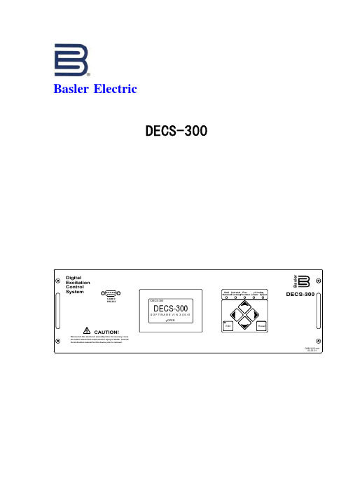
Basler ElectricDECS-300数字式励磁调节器技术说明书relsaBDECS-300巴斯勒电气公司二○○二年十月目录提要概述 (1)适用范围 (1)使用条件 (2)供货范围 (2)DECS-300数字式励磁调节器 (3)主要特点 (3)系统概述 (4)功能描述 (9)技术规格 (17)外形尺寸 (19)应用示例 (20)巴斯勒电气公司,全球最大的独立的励磁控制系统专业制造商之一,60余年励磁控制系统和自动电压调节器研发、设计、制造经验美国原装进口,世界顶级产品,通过ISO9002质量体系认证,符合IEC、ANSI、CSA、CE、UL、IEEE等组织的技术规范,亦完全符合中国相关的国家标准和行业标准DECS-300,最新一代数字式励磁调节器,技术先进成熟、集成度高、工艺精良、体积小巧、安全、可靠、使用方便,基本免除维护基于32位高档微处理器和高速数字信号处理器的用户化的灵活的设计,绝大部分参数可调整,可编程的输入输出,界面友好、功能强大的设置调试软件BESTCOMS TM,使DECS-300可以适用于任何功率、各种励磁方式的发电机组基于DECS-300的励磁系统已在全球数百台发电机组(1MV A~900MV A)上成功地运用,可靠性高,适应性强,性能优良价格接近国内同类系统,既可以成套提供完整的励磁、控制和保护组件,也可以仅使用励磁调节器改造现有的陈旧的系统快速的设计制造和较短的交货时间随时可以提供优质的产品和服务,解除用户的一切后顾之忧联系地址:江苏省南京市集庆路198号江苏通信大厦邮政编码:210006电话: 025-225 3994、225 7597、225 6571、225 7419传真:025-225 7730E-m a i l :wanxingquan@, power@Web Site :, 欢迎访问以上网站,查阅、下载巴斯勒电气的产品资料发电机励磁直接影响发电机、电厂和电网的安全稳定和经济运行,励磁控制系统是发电厂中极为重要的关键设备。
DECS100和DECS-250
ARXY
相关产品:
DECS-250主要功能特点
• BE1-整的发电机控制和保护系统。
• DGC-2020数字式机组控制器
提供机组和转换开关的控制、测量、保护和简单编程。操 作简单、性能可靠、耐用。
提供更多测量和实现更复杂的逻辑控制。
• 可实现逻辑编程,完善控制、保护等功能
ARXY
辅件:
DECS-250主要功能特点
• P-800交互式显示器 • - 通过7.5” (190.5 mm) 的人机界面,就地或远程查看发
电机系统参数。
• MVC手动电压控制器
-为励磁提供备用手动电源,以防AVR故障。
ARXY
DECS-250主要功能特点
辅助控制,-10V~+10V或者4-20mA
• 同期功能(可选)(注:所有AVR带有电压匹配功能) • 趋势、录波、实时在线监视和事件顺序记录 • 16组可编程输入接点,完善的控制功能 • 12组可编程输出接点,各种保护、报警、工作状态输出 • I/O扩展模块功能- AEM-2020 模拟量扩展模块- CEM-2020数字量扩展模块。
继电器输出 DECS-100的端子AL1和AL2是一个共用的报警输出接点,这 个常开、A型接点用于指示报警、保护联跳逻辑控制。
ARXY
DECS-100功能特点
功率输入、励磁输出:
输入功率可以是交流或者直流,单相或三相。
PWM控制输出,快速响应,抗干扰能力强等,适用于各类恶 劣环境下。 前面板指示灯: DECS-100前面板上有八个发光二极管(LED)用于指示各种 保护功能和运行模式。便于快速排查故障。
ARXY
四种控制模式:
DECS-100功能特点
自动电压调节(AVR)模式、手动(FCR)模式、恒无功功 率(VAR)模式、恒功率因数(PF)模式。PF、VAR可选功能。 无功调差补偿 DECS-100具有无功降落补偿特性以保证并列运行的发电机 之间的无功负荷的合理分配。 低频率限制(V/HZ限制) 当发电机频率掉到低于所选择的转折设定值时,DECS-100 自动调整电压给定值使发电机电压遵循所选择的 V/Hz曲线。
DECS100自动电压调节器使用手册
Basler ElectricDECS-100 自动电压调节器使用手册巴斯勒电气公司二○○三年五月翻译:万行全校核:万行全地址:南京市集庆路198 号江苏通信大厦4 楼邮政编码:210006电话:025-5220 7234 或5225 1013 转8202,5225 3994传真:025-5225 7730E-mail:wanxingquan@编号:9 2875 00 991版本:D 01/032003 年5 月于南京未经许可,请勿翻印、复印,违者必究!简介这本手册介绍了DECS-100 自动电压调节器的安装和操作。
主要包含下列内容:·概述和技术规格·人机接口·功能描述·安装·BESTCOMS调试软件·使用和故障诊断警告!为了避免人身伤害或设备损坏,只有合格的技术人员才允许完成本手册所描述的操作。
DECS-100 在运行时其后面板带有危险的电压。
后面板的接线应该在DECS-100 停止时进行。
小心在激活手动模式之前请注意必须估计其励磁等级。
如果励磁电流的等级与发电机不相匹配,则可能会导致出现致命的破坏性的高电压。
不正确的PID 参数将导致系统性能较差或设备损坏。
在上载一个设定文件之前,请先关断DECS-100 的工作电源并断开端子F+和F-到励磁绕组的接线,然后再加上DECS-100 的工作电源。
注意确认D ECS-100 通过机箱后面的接地端子采用不小于12AWG 的铜导线接地。
当DECS-100 和其它装置安装在同一个系统中时,推荐从每个单元到接地母线使用单独的导线。
i保密信息巴斯勒电气公司授权保密使用,并保留根据需要收回的权力,请互相谅解它不能以任何方式用于损害巴斯勒电气公司利益的地方。
本手册未能覆盖设备的所有细节和变化,也未能提供安装和操作时可能出现的各种意外情况的数据。
所有特性和选件的有效性和设计如有更改,恕不事先通知。
如果需要更多的资料,请与巴斯勒电气公司联系。
APPLICATION NOTES
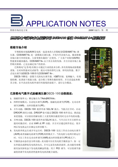
APPLICATION NOTES船舶市场改造方案 2009年12月,第一期巴斯勒电气数字式电压调节器DECS-100替换COSIMAT N+型调压器船舶市场介绍早期船舶市场随AVK 发电机一起进来的大多数配套COSIMAT N+调压器。
COSIMAT N+是一款模拟式调压器,开发年代比较久远。
随着船舶市场日新月异的发展,大量变频负载的广泛使用,广大客户对船用AVR 的性能要求越来越高,COSIMAT N+由于其自身的发展,并且目前市场上备件购买困难,已无法满足客户的需求。
巴斯勒电气(苏州)有限公司通过专业的技术分析,多次的现场试验数据采集,长时间性能对比试验等,提出可靠的替代方案。
即用高性能、数字式电压调节器DECS-100替代COSIMAT N+。
DECS-100是一款数字式的电压调节器,IGBT 控制,宽频输入,有效值检测,抗谐波干扰能力强,适合船上变频负载的使用。
并且改造起来极其方便,在不改动发电机外部任何接线的前提下,进行完全覆盖。
巴斯勒电气数字式励磁调压器DECS-100功能描述:1、 励磁控制单元:额定输出为7Adc@63Vdc ;2、 四种控制模式:自动电压调节(AVR),励磁电流调节(FCR),无功功率调节(VAR),功率因数调节(PF);3、 并车功能:DECS-100提供外部52L/M 接点,当接点打开时,启动DROOP(调差)功能。
DROOP 值可通过DECS-100软件设定,调试起来更便捷,可以很好的解决船上大量变频负载使用时无功不均的问题;4、 并网功能:DECS-100提供外部52J/K 接点,当节点打开并且软件功能同时激活时,启动VAR 或PF 功能。
并且可以通过软件设定,使并网后发电机运行在额定功率因数下;5、 发电机单机运行或并车运行时,DECS-100仅仅工作在自动电压调节(AVR)或者励磁电流调节(FCR)两种模式下。
当发电机与电网并联运行时,可以工作在无功功率调节(VAR)或功率因数调节(PF)模式下;6、 空载状态动态信息分析功能:此功能可以在发电机空载状态下,按一定比率提高或降低发电机的电压,并可记录发电机的波形。
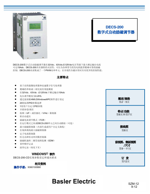
DECS-200产品说明
综合点型:
在线
高限电流等级(瞬间)的设定值可在0到30.0Adc之间调整,增量为0.1Vac。限制动作的时间范围可在0到10秒之
间调整,增量为1秒。
中限电流等级设定值可在0到20Adc之间设定,增量为0.1Vac。限制动作的时间范围可在0到120秒之间设定,增
量为1秒。
低限电流等级 设定值可以在0 到15Adc之间设定,增量为0.1Vac。限制动作的时间没有限制离线。
励磁过流保护 动作电流可在0到16Adc之间调整,增量为0.1Adc,带有反时限时间延迟。
励磁机二极管故障监测(EDM) DECS-200的EDM可以监测无刷励磁发电机二极管的开路和短路。为了实现这个功能,DECS-200要求用户输入发电机和励磁 机的极数(均可在0~20之间调整,增量为2)。二极管开路和短路的纹波阈值可以在0~100%的励磁电流之间调整。二极管开路 保护时间延迟可以在10~60秒之间调整,二极管短路保护时间延迟可以在5~30秒之间调整。
波形记录 可以存储8条记录。每条记录中可以记录多达6个变量。采样速率:每个记录600个数据点,触发动作可以在0~599个 数据点之间调整,数据点之间的间隔为4ms~10s(总的记录持续时间为2.4s~6000s)。
内部自动跟踪(可选):切换时,励磁电压的变化为额定值的±0.5%。
并列补偿/调差 既可以使用无功降落补偿也可以使用无功电流差(横流)补偿。使用可选的≤1A或者≤5A的CT输入,可在 0~30%之间调整发电机调差系数。线路电压降补偿也使用这个参数,只是调整范围为-30%~0。
励磁过压保护 动作电压可在1.0到325Vdc之间以1.0Vdc的增量进行调整,带有0.2到30秒的反时限时间设定,增量为0.1 秒。
发电机低电压保护 检测电压设定可在0到30kV之间以1Vac的增量调整,带0.5到60秒的反时限时间延迟,增量为0.1 秒。
柴油发电机组控制系统

世界上第一台柴油机
世界上第一台柴油机诞生于1893年的德国。蒸汽机发明后,鲁道夫.狄塞尔(RUDOLF DIESEL)—一位德国皮革商的儿子,在慕尼黑技术大学上学时对“蒸汽机”表现出了极大的兴趣,在他34岁那年(1892)取得了把空气压进容器并且和煤粉充分混合直至被压燃而提供动力的机械装置的发明专利。第2年,位于德国奥古斯堡的MAN公司根据这一专利制造出了世界上第一台柴油发动机的原型机,并取名叫‘狄塞尔(DIESEL)’发动机。像所有的新生事物一样,狄塞尔发动机从诞生到不断完善经历了漫长的过程。狄塞尔先生在他55岁那年不幸逝世了,没有能够见到他发明的发动机装在汽车上。10年之后,MAN公司终于在柏林的汽车展览会上推出了第一台装在卡车上的狄塞尔发动机。后来,设在曼海姆的奔驰公司制造出了带预燃室的狄塞尔发动机,并且把它装在了自己的卡车上。直到1936年,也就是狄塞尔先生去世23年后,梅塞得斯——奔驰公司才制造出了第一台装有狄塞尔发动机的轿车。 直到今天,柴油机的英文名称仍然是‘DIESEL ENGINE’—‘狄塞尔’引擎。
2
电流互感器
电力仪表(多功能保护继电器)
1
4
3
测量回路和电力监视
发电机回路的保护
目的: 防止发电机过载损伤 切除发电机和发电机故障 发电机断路器和馈电用保护装置进行选择切除动作,并迅速切除汇流故障 发电机并联运行时,防止原动机损伤 内容: 发电机过载保护 发电机短路保护 发电机逆功率保护 发电机欠电压保护 自动卸载
将交流或直流发电机与柴油机曲轴同轴安装,就可以利用柴油机的旋转带动发电机的转子,利用‘电磁感应’原理,发电机就会输出感应电动势,经闭合的负载回路就能产生电流。
这里只描述发电机组最基本的工作原理。要想得到可使用的、稳定的电力输出,还需要一系列的柴油机和发电机控制、保护器件和回路。
低电压调节器安装使用说明书2015

176~186V 187~198V
7 A B V R 2 .5
30K V A 三相调压器 一次原理图
R R
控制器逻辑控制功能: 1. 输入电压大于198V、小于230V持续20S,1KM闭合、2KM\3KM断开; 2. 装置电流大于设定值且持续20S,无论电压是多少,则1KM闭合、2KM\3KM断开; 3. 当输入电压在188~198V且持续10S,则2KM闭合; 4. 当输入电压在177~186V且持续10S,则3KM闭合;
低电压主要存在于农网线路中,农 网的 10kV 或 0.4KV 的配电线路供电半 径长。当供电半径超过合理的长度时, 线路末端电压损耗太大,导致电压偏 低。低压供电半径的长短与变压器布点 位置相关,它关系到供电电压质量、线 路损耗等重要经济指标。低压供电线路 呈单方向放射状,从而造成末端电压偏 低,解决这样的问题必须进行技术改 造,否则低电压问题会随着线路负荷的 增加而日益严重。
3、农网中的低电压存在具有复杂性,由
于供电线路的半径长,不是供电线路中
的所有用户都会低电压,有的地方电压
合适,有的地方电压会比较低,给供电
部门的低电压治理带来了不小麻烦。
4、同时农网中的低电压对电网也是有影
响的,1、增大线损。在输送一定电能时,
电压降低,电流相应增大,引起线损增
大;2、降低电力系统的稳定性。由于电
最低气温-40℃ 海拔:≤1000m 污秽等级:III 级 覆冰厚度:10mm 湿度:日相对湿度平均值≤95%
月相对湿度平均值≤90%
7.2、运行条件
额定电压:305V-380V 额定频率:50Hz 额定容量:10~100kVA
八、技术参数
序号 1 2
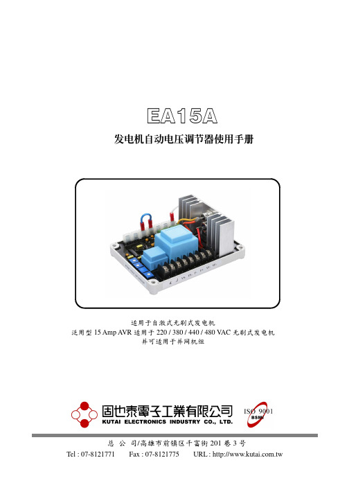
发电机自动电压调节器使用手册_8560
穩稳定定 電电壓压 低低頻频 壓压降降 調调整节 調调整节 調调节整 調调整节
尺寸与端子、旋钮 图一
发电机 输出电压 百分比% 发电机 输出电压 百分比%
120
100 80
50HZ 60
40 20
60HZ
0
10
20
30
40
50
60
发电机频率 (Hz)
低频动作曲线 图二
120 100 80 60 40 20
6.2.2 在发电机不并网时,避免 CT 二次电流 进入 AVR,导至电压下降.
6.3 连锁补偿
6.3.1 (如图六),在发电机未并网空载下,必 须将 “并网开关” 闭合,以保持其它并 网中发电机之补偿回路闭合,如果 “并 网开关” 在未并网时分开则会引起发 电机电压提早调节与变动。如果能使用 断路器的辅助接点做为 “并网开关” 是最适合的,当主接点 (ACB) 闭合时 辅助接点分开,当主接点分开时辅助接 点闭合.
4.4 无功调差(DROOP).
4.4.1 在使用(如图四)时,具有负载电流补偿 之功能,当远程电压在负载下会稍降 时,可经由电流互感器 CT 来补偿,当 CT 二次产生 5A,PF0.8 时 DROOP 可 补偿额定电压的 0 ~ 6 %.
4.4.2 此功能可适用于并联运转之发电机电 流补偿 (参阅 6.并联功能).
6
EA15A
5VAC 请重做如 A ~ B. 5.4 如剩磁电压大于 5VAC,但稳压器仍无
法建立电压时,请更换另一稳压器.
警告:过度励磁可能损坏AVR或发电机 励磁线圈.
6. 並網功能
6.1 并网补偿 6.1.1 当发电机做并网使用时,必须有一只电
流互感器(CT) 加在发电机的输出线, 其容量须大于 10VA 且在加负载时能产 生 3 ~ 5A (CT 二次侧). 6.1.2 CT 必须按装在输出三相中的其中一 相,且不可与电压调节器 (AVR) 之检 测电源同相. 6.1.3 (如图六)之接线中,相序为 R.S.T,当 相序为 R.T.S 时,CT 二次之极性必须 反接.
发电机励磁系统改造
发电机励磁系统改造摘要:针对进口余热发电机励磁调节器损坏无法购买备件的情况下,选用新的励磁调节器改造励磁系统解决发电机励磁系统故障问题关键词:励磁调节器;发电机;DECS-1001 引言在有色金属冶炼过程中,余热发电机组利用在生产流程中余热锅炉回收冶炼烟气的热能而产生的中压蒸汽发电,余热发电机组作为蒸汽梯级利用的核心部分,发电机组的稳定运行决定到余热回收利用率。
金昌冶炼厂余热发电机组作为蒸汽梯级利用投入运行,由于现场环境温度高、灰尘重等原因导致励磁系统控制板老化。
事后车间工程技术人员调节励磁板设置发电机组仍然无法并网,由于原励磁控制板在国外已经停产无法购买备件,所以决定对汽轮发电机组励磁系统进行改造。
2原励磁调节器组成及存在的问题2.1发电机励磁系统发电机为德国AVK公司的产品,具体参数如下:发电机型号DIG 140 i/4W,额定功率:3390 kVA额定电压 6000 V 接法:Y,额定电流:326 A功率因数:0.8 频率 50 Hz发电机采用维护量小的无刷励磁系统,其励磁调节器采用的是康明斯公司生产的COSIMAT N+和QPF,其中COSIMAT N+用于发电机电压调节,QPF控制板调节发电机并网的功率因数。
励磁调节器供电电源来自发电机辅助绕组UH1-UH2、WH1-WH2产生两路电源分别给电压调节器COSIMAT N+及功率因数控制器QPF供电。
电压调节器COSIMAT N+检测发电机三相电压、发电机B相电流,输出励磁电流给无刷励磁发电机的励磁绕组以控制发电机输出电压,在空载运行及并网阶段,发电机电压由内部给定电位器和外部给定电动电位器R1控制,并网完成后,发电机电压由功率因数控制器QPF输出的4~20mADC控制信号N、M/m控制,电压调节器控制板上还设置有各种控制电位器,如PID参数电位器、下垂电位器、V/F控制电位器等,通过运行调试可使发电机具有比较好的动态调节性能。
功率因数控制器QPF检测发电机A相、C相电压、B相电流并采集外部给定电位器功率因数给定值、功率因数控制允许信号,输出功率因数控制信号给电压调节器以达到发电机组并网运行时的恒功率因数控制,同时功率因数控制器上还有各种控制参数电位器,如PI调节电位器、无功功率最高限位电位器、基准校正电位器及各种控制方式的拨码开关,以实现恒功率因数控制、恒无功功率控制等目的。
发电机自动电压调节器使用手册_8452
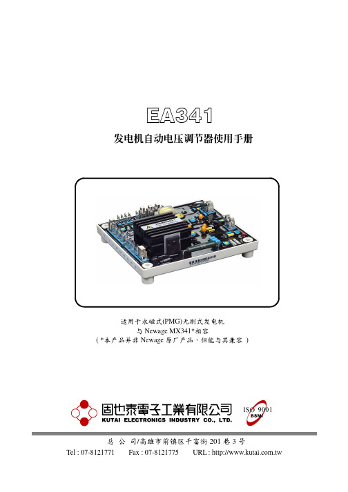
EA341發電机自動電壓調節器使用手冊适用于永磁式(PMG)无刷式发电机与Newage MX341*相容( *本产品并非Newage 原厂产品,但能与其兼容 )总 公 司/高雄市前镇区千富街201巷3号Tel : 07-8121771 Fax : 07-8121775URL : ______________________________________________________________________________________2EA3411. 技術參數检测输入 电压 190 ~ 264 V AC 二相或三相 温差稳定度 每℃变化,电压漂移0.05% (注2) 频率 50/60 Hz 以跨接铜片选择 外部电压调节 用1K Ω 1 Watt 电位器时为±10% (注3) 电源输入 电压 170 ~ 220 V AC 三相三线 电压缓慢建立时间 2秒电流 每相3A 发电机电流输出限制 负载10 Ω 灵敏度范围 0.5 ~ 1A 频率 100 ~ 120 Hz 过励磁保护 90V (出厂默认值) 励磁场输出 电压 最大120 VDC 时间延迟固定为10秒电流 连续2.7A (注1)非连续为10秒内6A 低频保护 转折点 95% Hz (出厂默认值) (注4) 电阻 最小15 Ω斜率 下降至30 Hz 时为 170% 电压建立 在A VR 输入端子需剩磁电压5 V AC 以上 电压修正(模拟输入) 最大输入 ±5 VDC (注5)消耗功率 最大12 Watt 灵敏度 每1 VDC 可调节5%发电机电压 电流补偿 负载 10 Ω 输入电阻 1K Ω 调压精度 < ±1% (发电机转速变动在4%内) DROOP 压降输入 负载 10 Ω振 动 3.3G @ 100 ~ 2K Hz 灵敏度 0.07A 对应5%压降 (在PF= 0时) 相对湿度 < 95%最大输入 0.33A操作温度 -40 ~ 70℃ (注6)尺 寸 150mm L * 135mm W * 40mm H 储存温度 -40 ~ 85℃ 重 量394公克 ± 2%2. 概述2.1 励磁电源来自三相永磁式发电机(PMG),如此A VR 的控制电路可隔离受非线性负载所引发的影响,并能减低发电机端的射频干扰,能承受发电机的短路电流是PMG 发电机的另一特色. 2.2 此A VR 可以藉由检测发电机主绕组的电压,以控制提供给励磁机定子以及主转子的电力,来维持发电机输出电压介于指定的范围内,并补偿负载、转速、温度及发电机的功因。
COOPER POWER SERIES电压调节器模拟器简介及连接方法说明书
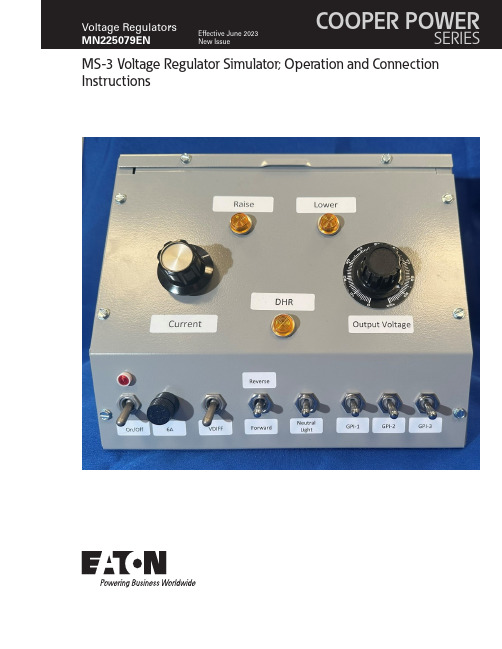
MS-3 Voltage Regulator Simulator; Operation and Connection InstructionsDISCLAIMER OF WARRANTIES AND LIMITATION OF LIABILITYThe information, recommendations, descriptions, and safety notations in this document are based on Eaton Corporation’s (“Eaton”) experience and judgment and may not cover all contingencies. If further information is required, an Eaton sales office should be consulted. Sale of the product shown in this literature is subject to the terms and conditions outlined in appropriate Eaton selling policies or other contractual agreement between Eaton and the purchaser.THERE ARE NO UNDERSTANDINGS, AGREEMENTS, WARRANTIES, EXPRESSED OR IMPLIED, INCLUDING WARRANTIES OF FITNESS FOR A PARTICULAR PURPOSE OR MERCHANTABILITY, OTHER THAN THOSE SPECIFICALL Y SET OUT IN ANY EXISTING CONTRACT BETWEEN THE PARTIES. ANY SUCH CONTRACT STATES THE ENTIRE OBLIGATION OF EATON. THE CONTENTS OF THIS DOCUMENT SHALL NOT BECOME PART OF OR MODIFY ANY CONTRACT BETWEEN THE PARTIES. In no event will Eaton be responsible to the purchaser or user in contract, in tort (including negligence), strict liability or otherwise for any special, indirect, incidental, or consequential damage or loss whatsoever, including but not limited to damage or loss of use of equipment, plant or power system, cost of capital, loss of power, additional expenses in the use of existing power facilities, or claims against the purchaser or user by its customers resulting from the use of the information, recommendations, and descriptions contained herein. The information contained in this manual is subject to change without notice.ii OperatiOn instructiOns MN225079EN June 2023ContentsDISCLAIMER OF WARRANTIES AND LIMITATION OF LIABILITY . . . . . . . . . . . . . . . . . . . . . . . . . . . . . . . . . . .ii SAFETY FOR LIFE . . . . . . . . . . . . . . . . . . . . . . . . . . . . . . . . . . . . . . . . . . . . . . . . . . . . . . . . . . . . . . . . . . . . . . . . .iv SAFETY INFORMATION . . . . . . . . . . . . . . . . . . . . . . . . . . . . . . . . . . . . . . . . . . . . . . . . . . . . . . . . . . . . . . . . . . . .iv Safety instructions (iv)PRODUCT INFORMATION . . . . . . . . . . . . . . . . . . . . . . . . . . . . . . . . . . . . . . . . . . . . . . . . . . . . . . . . . . . . . . . . . . .1 Introduction (1)Read this manual first (1)Additional information (1)Acceptance and initial inspection (1)Handling and storage (1)Quality standards. . . . . . . . . . . . . . . . . . . . . . . . . . . . . . . . . . . . . . . . . . . . . . . . . . . . . . . . . . . . . . . . . . . . . . . . . . . . . . . .1 Description of Feature (3)Directions to connect a control and tap-changer to the simulator (5)Connecting a CL-6 control to the MS-3 simulator (6)Control and MS-3 use and examples (7)iiiOperatiOn instructiOns MN225079EN June 2023iv MS-3 Voltage Regulator Simulator; Operation and Connection InstructionsOperatiOn instructiOns MN225079EN June 2023Safety for lifeEaton meets or exceeds all applicable industry standards relating to product safety in its Cooper Power™ series products. We actively promote safe practices in the use and maintenance of our products through our service literature, instructional training programs, and the continuous efforts of all Eaton employees involved in product design, manufacture, marketing, and service.We strongly urge that you always follow all locally-approved safety procedures and safety instructions when working around high-voltage lines and equipment, and support our “Safety For Life” mission.Safety informationThe instructions in this manual are not intended as asubstitute for proper training or adequate experience in the safe operation of the equipment described. Only competent technicians who are familiar with this equipment should install, operate, and service it.A competent technician has these qualifications:●Is thoroughly familiar with these instructions.●Is trained in industry-accepted high- and low-voltage safe operating practices and procedures.●Is trained and authorized to energize, de-energize, clear, and ground power distribution equipment.●Is trained in the care and use of protective equipment such as arc flash clothing, safety glasses, face shield, hard hat, rubber gloves, clampstick, hotstick, etc.Following is important safety information. For safeinstallation and operation of this equipment, be sure to read and understand all cautions and warnings.This manual may contain four types of hazard statements:Indicates an imminently hazardous situation which, ifnot avoided, will result in death or serious injury .Indicates a potentially hazardous situation which, if notavoided, could result in death or serious injury .Indicates a potentially hazardous situation which, if not avoided, may result in minor or moderate injury .NOTICEIndicates a potentially hazardous situation which, if not avoided, may result in equipment damage only .Safety instructionsFollowing are general caution and warning statements that apply to this equipment. Additional statements, related to specific tasks and procedures, are located throughout themanual.Hazardous voltage . Contact with hazardous voltage will cause death or severe personal injury . Follow all locally-approved safety procedures when working around high- and low-voltage lines and equipment .G103 .3Before installing, operating, maintaining, or testing this equipment, carefully read and understand the contents of this manual . Improper operation, handling, ormaintenance can result in death, severe personal injury, and equipment damage .G101 .0This equipment is not intended to protect human life . Follow all locally-approved procedures and safety practices when installing or operating this equipment . Failure to comply can result in death, severe personal injury, and equipment damage .G102 .1Power distribution and transmission equipment must be properly selected for the intended application . Itmust be installed and serviced by competent personnel who have been trained and understand proper safety procedures . These instructions are written for suchpersonnel and are not a substitute for adequate training and experience in safety procedures . Failure to properly select, install, or maintain power distribution and transmission equipment can result in death, severe personal injury, and equipment damage . G122 .21MS-3 Voltage Regulator Simulator; Operation and Connection InstructionsOperatiOn instructiOns MN225079EN June 2023Product informationIntroductionDocument MN225079EN contains instructions for theoperation and use of the Eaton Cooper Power series MS-3 voltage regulator simulator. The simulator is designed to be used with the CL -7 voltage regulator control fordemonstration and troubleshooting purposes. The MS-3 can also be used with a control and QD3 (T -350) tap changer.Read this manual firstRead and understand the contents of this manual and follow all locally approved procedures and safety practices before installing or operating this equipment.Additional informationThese instructions cannot cover all details or variations in the equipment, procedures, or processes described nor provide directions for meeting every possible contingency during installation, operation, or maintenance. For additional information, contact the Voltage Regulator Support Group at (866) 975-7347 or ***********************.Acceptance and initial inspectionEach MS-3 Voltage Regulator Simulator is in good condition when accepted by the carrier for shipment. Upon receipt, inspect the shipping container for signs of damage. Unpack the MS-3 Simulator and inspect it thoroughly for damage incurred during shipment. If damaged is discovered, file a claim with the carrier immediately.Handling and storageBe careful during handling and storage of the MS-3 Voltage Regulator Simulator to minimize the possibility of damage. If the assembly is to be stored for any length of time prior to use, provide a clean, dry storage area.Quality standardsISO 9001 Certified Quality Management System2MS-3 Voltage Regulator Simulator; Operation and Connection InstructionsOperatiOn instructiOns MN225079EN June 202331Figure 1 . Front View of MS-3 Simulator109111213144578623MS-3 Voltage Regulator Simulator; Operation and Connection InstructionsOperatiOn instructiOns MN225079EN June 2023Description of Feature1. Simulator Power Switch2. Simulator Power Fuse (6 A)3. Simulator Power Light4. Load Current Adjustment Dial5. Motor Raise Indicator Light6. Drag Hand Reset Indicator7. Motor Lower Indicator Light8. Output (Load) Voltage Adjustment Dial9. VDIFF (Voltage Differential) Switch – Changes thesource voltage type between a differential or source input.10. Power Flow Switch – Changes the direction of powerflow between forward, indeterminate, and reverse.11. Neutral Light Switch – Simulates the tap-changerneutral switch.12. General Purpose Input 1 (GPI 1) Switch – Actives GPI1which is programmed as default on the CL -7 for Voltage Reduction and uses Terminal 5 in the control wire harness.Operating GPI 1 switch when connecting the simulator to a CL -6 control will cause a 120 V short to ground,which may cause damage to equipment. See the section on connecting the simulator to a CL -6 control for more information.13. GPI 2 Switch – Actives GPI2 which is programmedfor Tap to Neutral as a default on the CL -7 and uses Terminal J in the control wire harness. This switch will not have any function when connected to a CL -6 control. See the section on connecting the simulator to a CL -6 control for more information.14. GPI 3 Switch - Actives GPI3 which is programmedfor Auto Tap Block as a default on the CL -7 and uses terminal BR in the control wire harness 15. Dual Connector Terminal Board16. Tap-changer Connector – Makes the connections to thetap-changer simulation circuitry of the simulator. 17. Control Connector – Connection point for control wireharness.18. Power Cord19. Ground Wire Connector4MS-3 Voltage Regulator Simulator; Operation and Connection InstructionsOperatiOn instructiOns MN225079EN June 202321516171819Figure 2 . Front View of MS-3 Simulator5MS-3 Voltage Regulator Simulator; Operation and Connection InstructionsOperatiOn instructiOns MN225079EN June 2023Connecting a control to the simulatorFollow these steps when connecting a CL -7 control to an MS-3 simulator.1. Connect the ground wire connector. See Figure 3.Figure 3 . Ground Wire Connector Connected2. Insert control wire harness connector into the terminalboard receptacle. See Figure 4. The connector can be plugged into either the top or bottom receptacle. Make sure the labels on the connector match with the labels on the receptacle.NOTICEIf the connector is not properly installed, control andsimulator damage will result.Figure 4 . Inserting control wire harness connector into the simulator terminal board receptacle3. If not already connected, insert the 20-positionsimulator tap-changer connector into a terminal board receptacle. This connection can be made to either the top or bottom connector. See Figure 5. Make sure the labels on the connector match with the labels on the receptacle.Figure 5 . Inserting 20-position connector with 4-wires into the simulator terminal board receptacle4. The control and MS-3 are ready to be used together asa unit.Directions to connect a control and tap-changer to the simulatorFollow these steps when connecting a voltage regulator control and QD3 tap changer to an MS-3 simulator:1. Follow steps 1 and 2 in the previous section to connecta control to the simulator.2. Disconnect the 20-positon connector shown in Figure 5from the terminal board receptacle. It may hang downto the side of the terminal board when not in use.6MS-3 Voltage Regulator Simulator; Operation and Connection InstructionsOperatiOn instructiOns MN225079EN June 20233. Insert the tap changer wiring harness connector intothe open terminal Board receptacle. See Figure 6 and 7. When making this connection make sure that the labels on the connector match with the labels on the receptacle.4. Use Figures 7 and 8 as a guide to install and connectthe wiring harness from the simulator to the top terminal board of the QD3 tap-changer.The circuits wired into the tap-changer connector are:●White – Neutral/Ground (G) ●Orange – Holding switch (HS) ●Blue – Motor raise (R3) ●Black/Green – Motor Lower (L3)●Black/Red – Neutral light (NL)●Figure 6 . Connector wired to QD3 tap-changerFigure 7 . Inserting the tap-changer connector and control into the simulator terminal board receptacleFigure 8 . Connecting the tap-changer wires onto the terminal block on top the tap-change rFigure 9 . Connection drawing from the simulator to the top terminal block of the tap-changerConnecting a CL-6 control to the MS-3 simulatorMost MS-3 functionality is compatible with the CL -6control. The exceptions to this are GPI 1 and GPI 2. The CL -6 connection for GPI 3 is the same as that of the CL -7.7MS-3 Voltage Regulator Simulator; Operation and Connection InstructionsOperatiOn instructiOns MN225079EN June 2023Instead of GPI 1 and GPI 2 connections in the wire harness of the CL -7, the CL -6 control has preprogrammed inputs on an orange Programmable Input/Output (PIO) connector on the side of the control.For GPI 1, the default function is Voltage Reduction Point 1. For the CL -6, PIO terminal 10 is used for the same purpose. To enable the GPI 1 switch to operate this point on the CL -6 control, the white wire connected to the simulator at terminal 5 must be disconnected and then connected to terminal 10 on the PIO. See Figure 10. This can be done using a spliced wire.Operating the GPI 1 switch with the CL -6 control connected to the MS-3 simulator without disconnecting the white wire connected to terminal 5 will cause a short to ground. This will operate the simulator fuse and could cause other damage.For GPI 2, the default function is Tap to Neutral. For the CL -6, PIO terminal 3 is used for the same purpose. To enable the GPI 2 switch to operate this point on the CL -6 control, the white/blue wire connected to the simulator at terminal J must be disconnected and then connected to terminal 3 on the PIO. See Figure 10. This can be done using a spliced wire.See the document MN225016EN, CL -6 series control installation, operation, and maintenance instructions, for more information on using the PIO on the CL-6 control.Figure 10 . GPI 1 and GPI 2 wires connected from the simulator to the dual-connector terminal boardControl and MS-3 use and examplesThe items in this section provide simulator use information and examples of how the simulator features affect theoperation of the control. These examples can be used as a basis for developing testing and demonstration procedures for connected controls.1. T ap Changer T ype Setting (FC 49): When a QD3tap changer is not connected to the control and the tap-changer simulator circuitry is used to simulate tap changer operations, the FC 49 setting of Cooper Spring Drive will give you the best operational results. When a QD3 tap changer is connected to the simulator, use the setting of Cooper QD3. 2. Powering the Simulator and Control: Toggle thesimulator power switch to On; the simulator power indicator light will come on. Turn the output voltage adjustment dial up to 85 to produce an output ofapproximately 120 volts. Toggle the control panel power switch to Internal. The control will power up and can now be programmed and demonstrated.3. Load Current Adjustment: With the power to thesimulator turned on and a control panel connected, rotate the output voltage adjustment dial clockwise to increases the load voltage sensed by the control. Read the control load voltage secondary display at Function Code (FC 6) or by using the Metering-PLUS Load Voltage display (Key 2). The compensated voltage secondary may also be adjusted and viewed at FC 8 or by using the Metering-PLUS Comp Voltage display (Key 1).4. Load Voltage Adjustment: With the power to thesimulator turned on and a control panel connected, rotate the load current adjustment dial clockwise to increases the load current sensed by the control. Read the control load current display at FC 9 or by using the Metering-PLUS Load Current display (Key 3).5. Drag Hand Reset: With the power to the simulatorturned on and a control panel connected, press the drag hand reset button or switch on the control. Observed that the DHR light illuminates on the simulator.6. Raise and Lower: With the power to the simulatorturned on and a control panel connected, place theControl Function switch on the control to Local Manual, toggle the Raise/Lower switch on the control panel to Raise. Observe that the Raise light illuminates on the simulator. The same can be done in the lower direction by operating the lower switch on the control to illuminate the Lower light.7. VDIFF Switch: With the power to the simulator turnedon and a control panel connected, Enter FC 7 on the control. The control display will display the SourceVoltage Secondary as calculated with the VDIFF Switch in the down position. The control is calculating the source voltage because the Load and Source voltage inputs are the same. Toggle the VDIFF Switch up to display a voltage without the calculation indication. This is because the source voltage input is now a differential voltage, and the control is displaying a source voltage that is measured.8MS-3 Voltage Regulator Simulator; Operation and Connection InstructionsOperatiOn instructiOns MN225079EN June 20238. Forward/Reverse Switch: With the power to thesimulator turned on and a control panel connected, press the Metering-PLUS Load Current button (Key 3). Put the Forward/Reverse Switch down for Forward; observe that the top line display shows Load Current (Value) Fwd. Place Forward/Reverse Switch up for Reverse; observe that the top line display shows Load Current (Value) Rev. Place Forward/Reverse Switch in the middle position; observe that the top line display Zero Load Current and neither Fwd nor Rev for direction.9. Neutral Light Switch: With the power to the simulatorturned on and a control panel connected, press the Neutral Switch down, the neutral light on the control panel will illuminate. ote: N When operating the neutral light switch, the controlwill sync its tap position to neutral. When the switch is release, the control will lose tap position tracking. To restore a valid tap position, enter a new tap position for demonstration purposes at FC 12. 10. GPI 1 switch: With the power to the simulator turnedon and a control panel connected, make these settings changes:●Volt a ge Reduction (FC 70) to Remote Latch●Remote Set #1 (FC 73) to 1.0 %.Press the GPI 1 button and observe the VoltageReduction status LED illuminates. View FC 71 and observe the voltage reduction in effect is 1%.11. GPI 3 switch: With the power to the simulator turnedon and a control panel connected, move the ControlFunction switch to Auto/Remote. Press the GPI3 button. Observe the Auto Tap Block LED status LED illuminates.9MS-3 Voltage Regulator Simulator; Operation and Connection InstructionsOperatiOn instructiOns MN225079EN June 2023his page is intentionally left blank.TEaton1000 Eaton Boulevard Cleveland, OH 44122United StatesEaton’s Power Systems Division 2300 Badger Drive Waukesha, WI 53188United States/cooperpowerseries© 2023 EatonAll Rights ReservedPrinted in USAPublication No. MN225079EN June 2023[Product#] [revision#]Eaton is a registered trademark.All trademarks are propertyof their respective owners.For Eaton‘s Cooper Power series productinformation, call 1-877-277-4636 or visit:/cooperpowerseries.。
巴斯勒DECS-100 AVR技术性能
DECS-100 AVR介绍巴斯勒电气的DECS-100 自动励磁调节器是一个基于微处理器的控制装置。
DECS-100 通过控制无刷励磁机的励磁绕组的电流来调节发电机的输出电压。
DECS-100 的输入功率可以来自一台多极的高频永磁发电机(PMG),或者取自发电机的输出端(常规的并励励磁系统)。
DECS-100 采用密封组件、板后安装设计,使用螺钉固定在塑料外壳中。
前面板LED 用于指示DECS-100 的状态和系统工况,后面板接线采用1/4 英寸的快速连接端子。
后面板上的9 针D 型连接器用于DECS-100 和IBM 兼容PC 的通讯。
特点DECS-100 具有下列特点和功能:四个控制模式:自动电压调节(AVR)、手动或励磁电流调节(FCR)、功率因数调节(PF)和无功功率调节(VAR)可编程的稳定性设定在 AVR模式下具有斜率可调的软起动和电压建立控制在AVR、VAR 和PF 控制模式下的过励限制(OEL)低频率(V/Hz)调节AVR模式下的发电机电压(均方根值)三相或单相检测/调节母线电压(均方根值)单相检测发电机电流单相检测,用于测量和调节励磁电流和励磁电压检测, 一路模拟量输入,用于给定值的远方比例控制五路接点输入,用于系统接口一路共用的输出继电器,用于报警指示和跳闸功能四个保护功能(磁场过电压、磁场过电流、发电机过电压和检测消失)发电机并列运行时的无功降落补偿和横流补偿,后面板 RS-232 通讯口,用于和PC 通讯,使用BESTCOMS 软件可以方便快速地设置和控制DECS-100发电机电压检测类型: 1 相或3 相,4 个范围功耗: <1VA/相端子: E1,E2,E350Hz范围 1: 100Vac(85~132Vac)范围 2: 200Vac(190~220Vac)范围 3: 400Vac(380~440Vac)范围 4: N/A60Hz范围 1: 120Vac(85~132Vac)范围 2: 240Vac(170~264Vac)范围 3: 480Vac(340~528Vac)范围 4: 600Vac(540~660Vac)无功降落补偿DECS-100 具有无功降落补偿特性以保证并列运行的发电机之间的无功负荷的合理分配。
DECS-100说明书
这个功能允许 DECS-100 匹配发电机的电压。这个特性代替了自动同期装置中的同类功能,因而可以使用便 宜的同期装置以节省费用。
软起动
软起动功能是发电机起励期间的电压限制器。它限制发电机电压的超调,尤其是在发电机初次起动时可能出 现这种情况。
无功功率/功率因数控制
集成的无功功率/功率因数控制节省了用户购买和安装完成相同功能的远方控制装置的费用。这个功能通常 用于发电机并列运行而不能控制电网电压的情况下,设定好以后,DECS-100 将自动调节发电机输出的无功 功率或功率因数。
机械规格
工作温度: 储存温度: 冲击: 振动:
盐雾: 重量: 运输重量: 尺寸:
-40℃~+70℃ -40℃~+80℃ 在三个正交平面上为 20g 1.2g,5~26Hz 0.036 英寸振幅,27~52Hz 5.0g,53~500Hz 按照 MIL-STD-810E 方法 509.3,通过 48 小时运行测试 2.42 磅(1.10 千克) 2.88 磅(1.31 千克) 5.34〞(135.6mm)宽×10.82〞(274.8mm)高×2.84〞(72.1mm)深
5
DECS-100 数字式自动励磁调节器
BESTCOMS 软件界面
6
接线
DECS-100 数字式自动励磁调节器
图 2-典型的接线图-PMG 应用、ABC 相序、三相检测
7
尺寸
DECS-100 数字式自动励磁调节器
图 3-DECS-100 尺寸
图 4-安装和开孔尺寸
8
DECS-100 数字式自动励磁调节器
温度漂移:
±0.5%(在 1 小时内温度变化 40℃)
响应时间:
<1 个周期(A/D 转换器限制)
中文双DECS 200柜体说明手册
发电机励磁系统操作手册设备名称:双 DECS 200 调节器励磁柜目录1图片 (3)2概述 (4)3主要元器件及其功能 (4)4系统描述 (5)4.1如何启动系统 (5)4.1.1启动操作步骤 (5)4.2其他功能 (5)4.3电压检测回路 (6)4.4并列运行以及横流补偿回路 (6)4.4.1调差控制 (7)4.4.2VAR/PF调节模式 (7)4.5主备调节器间的切换 (7)4.6继电器 (7)5输出接点 (7)5.1输出继电器#1、#2、#3 (8)5.2输出继电器RP1,RP2,RP3 (8)5.3输出继电器K2,K27,QF1,QF2,K11 (8)6维护 (8)7试运行 (9)8常见故障及排除 (10)9修订记录 (10)本说明书描述了控制柜的完整调节系统,包括:*2个AVR(自动电压调节器)DECS-200(RE1&RE2);*2个接触器K1&K2(用于切断功率输入);*1个带机械自锁装置的接触器KB(用于转换主通道和备用通道);*2个ICRM-15(用于抑制DECS-200涌流);*2个断路器QF1&QF2 (用于在系统过电压时将DECS-200从功率输入中切除);*2个带指示灯按钮(用于DECS-200的起、停);*2个带指示灯按钮(用于选择主、备核心);*1个3极开关(用于升高/降低DECS-200的设定值);*1个3极开关(用于AVR/FCR模式的选择);*1个4极开关(用于选择发电机电压表显示的电压相位);*1个自锁按钮(用于DECS-200预置位);*1个按钮(用于系统复位);*1个按钮(用于试验所有能够点亮的指示灯);*2个指示灯(用于系统故障或报警指示);*1个电阻器(用于系统停止时快速灭磁);*1个过电压继电器(用于系统的过电压保护);*2个BE3-74SH 继电器(用于过励报警和故障的独立指示);3主要元器件及其功能∙RE1(第50页):此AVR是DECS-200,作为主通道的AVR,其额定输出15A@125Vdc。
狄利欧-松木 集成发电机控制器与自动电压调节器说明书

The firstintegrated Genset Controller &Automatic Voltage Regulator.By Leroy-Somer.At Leroy-Somer,we work with gensetsmanufacturers every day.As true business partners andindustrial alternator experts,we’re bringing somethingnew to the table - somethingthat will change the waygensets are built and used.For decades, alternatorsand engines have runside by side. It is time tobring them together as atrue integrated system.It’s time to take control.KEY FEATURESThe ControlReg features everything you’d expect from a genset controller, supercharged with advanced regulation settings.LEROY-SOMER UTILITY SOFTWAREComplete control & monitoring software providing access to all settings.Faster assembly Easier configuration Advanced monitoring…• Logic sequences programmingfor incidents & events handling • Trending curve capability allowing signals analysis and alarms setup • Data monitoring & broadcasting capabilities • User profiles and factory presets management • CANBus for engine with electronic regulation • MPU for engine with mechanical regulation • Island, Auto Mains Failureand Load Take Over modesPlus…- Total control through backlit LCD- GPRS communication (option)•Engine control:start preparation, localor remote start / stop sequences•Voltage regulation & engine help:voltagecontrol, adjustable U/f and softstart,alternator protection incl. de-excitation•Genset protections: fuel level, water temp.,oil pressure, over/underspeed…To design & program the ControlReg software & interface,we worked in partnership with DEIF, a recognized expertin gensets controllers. Together we built a productthat exceeds safety & reliability benchmarks.It’s time toTAKE CONTROLDesigned for GensetsmanufacturersLeroy-Somer40 – 42 – 44AlternatorPre-mountedcablingControlReg©200 or 200P Our “value pack”:Cost-efficient,reliable & easy solution With ControlReg, the alternator is connected directlyto the control panel. The terminal box is gone, meaning fewer cables, smaller footprint, and quicker assembly.Advanced configuration options to fit all applications and engines. Designed for quick installation and testing, saving time on the production line.AVR controls on the front panel mean easierdaily operations for the end-user...and easier support for you!KEY FIGURESFor gensets up to 150kVA/KWUp to 4A excitation currentSHUNT excitation systemVoltage range: 120 – 480 VAC Voltage regulation accuracy: +/- 0.5% 5x digital outputs (incl. fuel & start)6x configurable analog/digital inputs (heat sensing, fuel level…)IP65 protection on the front faceEND-USER BENEFITSDirect access to regulation settingsNo electrical /mechanical risks during configurationEasy access to logs & advanced settingsWORK WITH US TODAYAs an expert in industrial alternators, we can help you develop, qualify, test and market ControlReg powered gensets. Our sales and engineering teams are available to work with your team onsite. We’re committed to providing the quality and operational results you expect.CONTACT USPhone: +33 (0) 545 644 367 / 632Email: ***********************************.comABOUT LEROY-SOMER:Leroy-Somer Electric Power Generation, a business unit of the Nidec Group, is the global leader in industrial alternators with power ranging from 10kW to 25MW. With its two leading brands, Leroy-Somer and Kato Engineering, Leroy-Somer Electric PowerGeneration works with generator set manufacturers and electric power producers worldwide to help the industry provide reliable and efficient power solutions. Leroy-Somer Electric Power Generation has over 5,000 employees, 10 production sites worldwide and a global service network. For more, visit /epg MORE INFORMATIONScan the QR code or visit to:• Download the datasheet, maintenance manual and software.• Get more information © Nidec 2017. The information contained in this brochure is for guidance only and does not form part of any contract. The accuracy cannot be guaranteed as Nidec have an ongoing process of development and reserve the right to change the specification of their products without notice. Moteurs Leroy-Somer SAS. Headquarters: Bd Marcellin Leroy, CS 10015, 16915 Angoulême Cedex 9, France. Share Capital: 65 800 512€, RCS Angoulême 338 567 258.5394 e n – 2017.11 /b。
发电系统参数设置

发电系统培训教材(参数设置与维护)编写:缑建平发电系统培训教材(参数设置与维护)系统组成SPM-D11参数设置DECS-100参数设置2301A/2301D参数设置发电系统故障现象与排除石油钻机发电系统模拟发电系统数字发电系统节能发电系统EGCP-3控制器ComAp控制器罗斯海尔发电系统SPM-D11控制器VOLOV并车系统SPM-D11参数设置⏹SPM-D11电源管理器通过发电机侧电压互感器,网侧电压互感器,发电机侧电流互感器,网侧电流互感器,实现柴油发电机的自动同步并网控制、发电机组间有功、无功负荷均衡控制;⏹实现发电机过压、欠压、过频、欠频,逆功率等保护功能。
序号参数选项设定值备注1 Rated frequency fn=50Hz2 Generator frequency set point=50Hz3 Generator Voltage Transformer secondary=100V4 mains voltage Transformer secondary=0.600kV5 Gen voltage Transformer primary=0.600kV6 mains voltage Transformer primary=0.600kV7 Rated voltage Vn=100V8 Gen voltage setpint=100V9 Current transformer Generator 2000/510 Connection type Generator 1W2序号参数选项设定值备注11 Angel adjustment Gen.current 00012 Rated power Generator 1200kW13 Automatic idle running OFF14 Mode Terminal 6 Release control15 f control type Analog16 f control output +/-2.5V17 f control output Init.state 50%18 Freq.controller ON19 Freq.controller Isol.oper ON20 Freq.contrer Ramp 05.0Hz/s序号参数选项设定值备注21 output F control (max)100%22 output F control (min) 0%23 Freq.controller Gein Kp=1524 Freq.controller Reset Time Tn=2.5S25 Freq.controller Derivative-action Time Tv=0.02S(3#0.04S)26 V control.type Analog27 V contr.output +/-3V28 V control output Init.state 50%29 Volt.controller ON30 Volt.controller Isol.oper ON序号参数选项设定值备注31 V control Ramp25V/S32 output V control output(max)100%33 output V control output (min) 0%34 Volt.controller Gain Kp=1535 Volt.controller Reset Tn=2.5S36 Volt.controller Derivat-action Time Tv=0.02S37 Power.factor.control OFF38 Power controller OFF39 Power controller P max100%40 Power controller p main00%序号参数选项设定值备注41 Warm up load setpoint 25V/S42 Warm up load time 100%43 Download and open GCB 0%44 Power controller P set1 Kp=1545 Power controller P set2 Tn=2.5S46 Power setpoint external Tv=0.02S47 Power controller Ramp OFF48 Power controller Gain kp OFF49 Power controller Reset Tn 100%50 Power controller Derivat TV 00%序号参数选项设定值备注51 Gen active-power Monitoring ON52 Power monitoring threshold 80%53 Power monitoring Hysteresis 20%54 Power monitoring Delay time 10S55 Active power load-share ON56 Act load share Factor 30%57 Reactive power loade-share ON58 Reac load share factor 30%59 Synchronizing functions ON60 Synchronization df max 0.18HZ序号参数选项设定值备注61 Synchronization df min -0.1HZ62 Synchronization dv max 6V63 Synchronization Brk hold T>0.2S64 Phase matching ON65 Phase matching Max phase <766 Phase matching Dwell time 0.2S(3#2.2 S)67 Phase matching Gain 268 Phase matching df start 0.2HZ69 Sync time contr Alarm ON70 Sync time contr Delay time 120S序号参数选项设定值备注71 Gen.circ.break.Dead bus op ON72 Dead bus op GCB df max 0.25HZ73 Dead bus op GCB dfv max 10V74 Reverse/main pow monitoring ON75 Reverse/min pow threshold -10%76 Reverse/min pow Delay time 3S77 Gen overload monitoring ON78 Gen overload monitoring Threshold 120%79 Gen overload Delay time 20S80 Gen freguency –monitoring time ONSPM-D11参数设置序号参数选项设定值备注81 Gen overfreg f>55HZ82 Gen overfreg Delay time3S83 Gen.underfreg F<45HZ84 Gen.underfreg Delay time3S85 Gen.underfreg ON86 Gen.voltage U>107V87 Gen.overvotage Delay time3S88 Gen. undervoltage U<93V89 Gen undervoltage Delay time3S90 Auto-acknowledge messages ON91 Acknowledge message aft 1S电压调节器DECS-100参数设置DECS-100特点及功能⏹型号:DECS-100-A05 ⏹电压:88~250VAC,单相或三相⏹频率范围:50~400Hz ⏹功率:650VA⏹通讯接口:RS-232 ⏹励磁额定输出:63VDC,7ADC•A-没有无功功率和功率因数控制 •0-无电压匹配•5-CT 二次侧电流5ARS232通讯口电压调节器DECS-100参数设置标题栏菜单栏工具栏电压调节器DECS-100参数设置通讯端口选择通讯设置:波特率4800、无奇偶校验、数据位8位、停止位1 点击初始化进行连接电压调节器DECS-100参数设置自动电压调节给定值 精确电压调整的范围设定无差调节给定值标题栏 菜单栏 工具栏电压调节器DECS-100参数设置发电机软启动时电压上升时间的限制。
- 1、下载文档前请自行甄别文档内容的完整性,平台不提供额外的编辑、内容补充、找答案等附加服务。
- 2、"仅部分预览"的文档,不可在线预览部分如存在完整性等问题,可反馈申请退款(可完整预览的文档不适用该条件!)。
- 3、如文档侵犯您的权益,请联系客服反馈,我们会尽快为您处理(人工客服工作时间:9:00-18:30)。
保密信息
巴斯勒电气公司授权保密使用,并保留根据需要收回的权力,请互相谅解它 不能以任何方式用于损害巴斯勒电气公司利益的地方。
本手册未能覆盖设备的所有细节和变化,也未能提供安装和操作时可能出现 的各种意外情况的数据。所有特性和选件的有效性和设计如有更改,恕不事先通 知。如果需要更多的资料,请与巴斯勒电气公司联系。
改进
首次发布 在第五章 BESTCOMS 软件(Windows 操作系统)和第 六 章 BESTCOMS 软 件 ( Palm 操 作 系 统 ), 安 装 BESTCOMS 的第二步,DECS-100 CD-ROM 中增加一 个自动运行程序 在第五章 BESTCOMS 软件(Windows 操作系统)增加 嵌入软件一节 修正使用手册中的一些小的错误 修改对于随机提供的安装螺钉的拧紧力矩的要求 在第五章 BESTCOMS 软件(Windows 操作系统)和第 六章 BESTCOMS 软件(Palm 操作系统),修改内容和 插图,以适应软件功能的增强 使用手册中的电压匹配时间调整范围从 0~300 秒改为 1~300 秒 改正第五章和第六章中的图号
ii
产品改进记录
下面是 DECS-100 的嵌入软件、硬件和 BESTCOMS 软件的改进记录汇总。 对本使用手册(9 2875 00 991)的相应的修订也一同列出。改进记录按照时间先 后顺序列出。
嵌入软件 版本和日期 1.09.XX, 01/01 1.11.XX, 07/01
1.12.XX, 03/02
1 相(B 相),50/60Hz 最大持续电流 1Aac 最大持续电流 5Aac
<0.1VA CT1,CT2
母线电压检测(选件)
类型: 功耗: 端子:
50Hz 范围 1: 范围 2: 范围 3: 范围 4:
60Hz 范围 1: 范围 2: 范围 3: 范围 4:
1 相,4 个范围 <1VA/相 B1。B3
iv
目录
在每个章节的前面有一个目录,提供了该章的详细信息,这本手册的章节安 排情况如下: 第一章 概述.....................................………………………………………… 1-1 第二章 人机接口...............................………………………………………… 2-1 第三章 功能描述...............................………………………………………… 3-1 第四章 安装...............................……………………………………………… 4-1 第五章 BESTCOMS 软件(Windows 操作系统)…………………………… 5-1 第六章 BESTCOMS 软件(Palm OS 平台)……...…………………………... 6-1 第七章 维护和故障处理...........……………………………………………… 7-1
-3~+3Vdc -30%~+30%偏移 1kΩ A,B
通讯口
接口: 连接: 波特率: 数据位: 奇偶校验: 停止位:
全双工 RS-232 后面板 DB-9 型连接器 4800 8 无
1
输入接点
类型: 浸润电压: 标准功能端子
空接点 13Vdc(DECS-100 提供)
1-3
单独/并列: 52L,52M
编号:9 2875 00 991 版本:D 01/03 2003 年 5 月于南京 未经许可,请勿翻印、复印,违者必究!
简介
这本手册介绍了 DECS-100 自动电压调节器的安装和操作。主要包含下列内 容: ·概述和技术规格 ·人机接口 ·功能描述 ·安装 ·BESTCOMS 调试软件 ·使用和故障诊断
FCR(手动)控制模式
调节范围: 步长:
0~7Adc 0.1Adc
v
vi
第一章 概述
概述
巴斯勒电气公司的 DECS-100 自动电压调节器是一个基于微处理器的控制 装置。DECS-100 通过控制无刷励磁机的励磁绕组的电流来调节发电机的输出电 压。DECS-100 的输入功率可以来自一台多极的高频永磁发电机(PMG),或者 取自发电机的输出端(常规的并励励磁系统)。
型号
概述
DECS-100 的电气性能和工作特征采用一组符号和数字定义。装置型号和详 细的选件说明在后面板的标签上。在收到 DECS-100 后,请注意检查型号是否和 您的要求、包装清单相符合。
1-1
型号 图 1-1 是型号表,描述了 DECS-100 的电气性能和工作特征。
DECS-100
——
VAR/PF 控制 A)无 VAR/PF 控制 B)带 VAR/PF 控制
警 告!
为了避免人身伤害或设备损坏,只有合格的技术人员才允许完成本手册所描 述的操作。
DECS-100 在 运 行 时 其 后 面 板 带 有 危 险 的 电 压 。 后 面 板 的 接 线 应 该 在 DECS-100 停止时进行。
小心
在激活手动模式之前请注意必须估计其励磁等级。如果励磁电流的等级与发 电机不相匹配,则可能会导致出现致命的破坏性的高电压。
C, 05/02
D, 01/03
New Version(检查更新版本)按钮 在“Save to File”时增加日期/时间标记 增加版本检查功能 增加口令保护 增强版本检查功能
改进
首次发布 增加封装外壳的深度 开始提供安装螺钉 在一些功率元件和散热底座之间增加 SIL-PADS 在后面的标签上增加制造地点 改进 EEPROM
增:
6U,7
减:
6D,7
可选功能端子
VAR/PF 允许: 52J,52K
电压匹配: VM,VMC
共用报警输出
类型: 额定负荷: 承受: 分断: 工作电压: 端子:
A型 7Aac/Adc 持续 30Aac/Adc,0.2 秒
7Aac/0.1Adc 最大 240Vac/250Vdc AL1,AL2
励磁输出
DECS-100 采用密封组件、板后安装设计,使用螺钉固定在塑料外壳中。前 面板 LED 用于指示 DECS-100 的状态和系统工况,后面板接线采用 1/4 英寸的 快速连接端子。后面板上的 9 针 D 型连接器用于 DECS-100 和 IBM 兼容 PC 的 通讯。
特点
DECS-100 具有下列特点和功能: 四个控制模式:自动电压调节(AVR)、手动或励磁电流调节(FCR)、功率 因数调节(PF)和无功功率调节(VAR) 可编程的稳定性设定 在 AVR 模式下具有斜率可调的软起动和电压建立控制 在 AVR、VAR 和 PF 控制模式下的过励限制(OEL) 低频率(V/Hz)调节 AVR 模式下的发电机电压(均方根值)三相或单相检测/调节 母线电压(均方根值)单相检测 发电机电流单相检测,用于测量和调节 励磁电流和励磁电压检测 一路模拟量输入,用于给定值的远方比例控制 五路接点输入,用于系统接口 一路共用的输出继电器,用于报警指示和跳闸功能 四个保护功能(磁场过电压、磁场过电流、发电机过电压和检测消失) 发电机并列运行时的无功降落补偿和横流补偿 后面板 RS-232 通讯口,用于和 PC 通讯,使用 BESTCOMS 软件可以方便快 速地设置和控制 DECS-100
BESTCOMS (Windows OS)
版本和日期 1.02.XX, 02/01 1.03.XX, 08/01
1.04.XX, 04/02
BESTCOMS (Palm OS) 版本和日期 1.01.XX, 01/01 1.02.XX, 08/01
改进
首次发布 在开始运行的前 5 秒中允许保护功能起动 修改 OEL 给定值比例因子以兼容 BESTCOMS(版本 1.03.00) 对增益标幺值增加比例因子 确定最小电压调节值为额定检测电压的 30% 增加检测 CT 类型的寄存器
励磁绕组电阻: 端子: 额定持续输出: 10 秒额定强励
200Vac 输入: 110Vac 输入:
最小 5Ω F+,F63Vdc,7Adc
135Vdc,15Adc 90Vdc,10Adc(励磁绕组 9Ω) 75Vdc,15Adc(励磁绕组 5Ω)
AVR 控制模式
调节范围: 电压调节:
温度漂移: V/Hz 特性:
改进
首次发布 OEL 比例因子从 100 改为 1,000 以匹配嵌入软件(版 本 1.11.01)的改进 OEL 缺省设定值从 1 改为 15 所有保护功能的缺省设定改为允许 增加法语地区设定支持功能 改进 BESTCOMS 兼容以前的所有版本的嵌入软件 增加任何地区设定支持功能 对采用 1.12.01 及以后版本嵌入软件的 DECS-100,允 许读取其 CT 二次侧值 简化 Analysis(分析)界面 对于发电机和母线 PT 变比不同的情况,增加了计算和 发送电压匹配参考点的功能 Ki 最小设定值从 0 改为 0.01
100Vac(85~132Vac) 200Vac(190~220Vac) 400Vac(380~440Vac) N/A
120Vac(85~132Vac) 240Vac(170~264Vac) 480Vac(340~528Vac) 600Vac(540~660Vac)
1-2
发电机电流检测
类型: X1X 型: X5X 型: 功耗: 端子:
电压匹配 A)无电压匹配 B)带电压匹配
图 1-1. DECS-100 型号 例如:如果型号是 A 1 5,则装置的性能和工作特征如下: A——没有无功功率或功率因数控制 1——电压匹配 5——CT 二次侧电流 5A
CT A) 1A CT B) 5A CT
技术规格
DECS-100 的电气和物理技术规格如下表所示。
100Vac(85~132Vac) 200Vac(190~220Vac) 400Vac(380~440Vac) N/A
