009正式 1#机轴封供汽管道蒸汽吹扫特殊施工措施
极氪009电芯参数

极氪009电芯参数极氪009的电芯参数可真是个超有趣的话题呢!一、电芯类型。
极氪009采用的是宁德时代的电芯哦。
宁德时代在电池领域那可是相当厉害的存在,就像电池界的超级明星一样。
这种电芯是三元锂电池呢。
三元锂电池有个很棒的特点,就是能量密度比较高。
这就好比一个小小的电池包,却能储存很多的能量,就像一个小小的口袋能装下好多好多宝藏一样。
二、电池容量。
它的电池容量超级可观。
大容量的电池就像是一个能量满满的大油箱,能让极氪009跑得更远。
具体的容量数值呢,能够很好地满足日常出行的需求,不管是短途的城市通勤,还是稍微长一点的周边游,都不用担心电量不够的问题。
比如说,你要是想开车去郊外野餐或者去临近的城市看望朋友,它的电量都能稳稳地支撑你到达目的地,不会把你丢在路上,那可太尴尬啦。
三、充电性能。
1. 快充。
极氪009的电芯在充电方面也很厉害。
快充功能就像是给汽车安装了一个超级加速器。
当你在高速服务区或者有快充设备的充电站的时候,它能快速地补充电量。
你想象一下,就像你渴了的时候,有一个超级大的吸管,能让你快速喝到水补充能量一样。
这样一来,你不需要长时间等待充电,节省了很多时间,可以更快地继续你的旅程。
2. 慢充。
当然啦,慢充也有它的好处。
慢充就像是小火慢炖,对电池的保养比较好。
如果你晚上回家把车停在车库里,插上慢充线,就像给车安排了一个温柔的夜间护理。
第二天早上起来,车又充满电啦,精神饱满地准备陪你开启新的一天。
四、安全性。
电芯的安全性也是极氪009非常重视的一点。
毕竟安全第一嘛,这就像我们出门要系好安全带一样重要。
这种电芯在设计和制造过程中采取了很多安全措施。
比如说,它有很好的热管理系统。
就像给电池安装了一个空调,不管是在炎热的夏天还是寒冷的冬天,都能让电池保持在一个合适的温度环境下工作。
如果电池温度过高或者过低,就可能会出现问题,但是有了这个热管理系统,就像是给电池穿上了一件恒温的衣服,让它舒舒服服地工作,也让我们开车的时候更加安心。
深远009滑动尾架安装教程(一)
深远009滑动尾架安装教程(一)
深远009滑动尾架安装教程
准备工作
•确保你已购买了深远009滑动尾架的套件
•准备一套工具,如扳手、螺丝刀等
•寻找一个宽敞的工作区域,以便安装过程更加顺利步骤一:拆解原有尾架
1.找到并定位飞行器的原有尾架连接点
2.使用工具逐个拆下原有尾架连接的螺丝
步骤二:安装滑动尾架
1.将深远009滑动尾架的各个零件整理好
2.在飞行器上找到需要安装滑动尾架的位置
3.确保尾架连接点的平整并清理干净
4.将滑动尾架的底座对齐并固定在尾架连接点上
5.依次安装其他滑动尾架的零件,注意螺丝的紧固程度
步骤三:调整尾架角度
1.调整滑动尾架的角度,使其与飞行器平衡
2.使用工具松开相应螺丝,进行角度调整
3.调整完成后,再次紧固螺丝,确保尾架的稳定性
步骤四:测试滑动效果
1.确保滑动尾架安装完毕后,没有松动或不稳定的地方
2.在安全的环境下进行一次试飞,观察滑动尾架的运动效果
3.如果发现滑动效果不理想,重新检查并调整尾架的安装
注意事项
•在安装过程中,小心不要损坏其他飞行器的零件
•确保滑动尾架的各个零件连接紧密,不可有松动
•如果安装过程中遇到问题,可参考滑动尾架的安装说明书
•在试飞前,务必检查飞行器的其他部件是否正常工作以上就是关于深远009滑动尾架安装的详细教程,希望对你有所帮助。
祝你安装顺利,飞行愉快!。
X-009工作服管理制度
工作服管理制度一、工作服管理目的为树立和保持公司良好的公众形象,进一步规范化管理。
二、工作服的发放关于工作服的配给,根据各位员工的实际需要提报数量及尺寸规格,由物业经理审批后,统一采购,再统一发放。
1、工作服分夏装、冬装两季工作服各两套,一年共四套工作服。
2、正式的合同制员工即可领用当季的工作工作服两套。
3、每年以4月30、10月30日为换装时间三、员工工作时间着装及仪表要求(一)所有员工着装要求1、所有员工须按照公司规定着装,保持良好的精神风貌,树立良好的公司形象。
2、工作时间须着公司统一工作服;注意仪容仪表,穿着整洁、得体、大方。
3、着工作服时,应搭配与工作服颜色、款式的袜子和黑色皮鞋;鞋应保持清洁光亮,无破损并符合工作要求;在工作场所不得赤脚、不得穿拖鞋、拖鞋式凉鞋等。
4、工作服应经常换洗,不得出现掉扣、错扣、脱线现象。
5、工作时间应保持口腔清洁、双手整洁;勤剪指甲,指甲不得留的过长,不得涂颜色过艳丽指甲油。
6、工作时间必须佩戴公司统一发放的工作牌,并佩戴在左胸前适当位置。
(二)男员工着装要求1、头发梳理整齐、大方;头发前不过眉,旁不过耳,后不盖衣领;不得剔光头;不得留胡须。
2、工作时间不得光膀子或穿挎拦背心及大短裤。
(三)女员工着装要求1、头发梳理整齐,发型(包括发式、颜色)不得太夸张;提倡化淡妆,金银首饰或其他饰物应佩戴得当。
2、着裙装时,外露袜子须穿肉色或黑色丝袜。
3、尽量避免用过浓的香水。
四、员工工作服配制说明1、离职(辞退)收取服装费用时,按服装的实际费用计算。
(1)自工作服发放之日起,工作满一年以上者,辞职(辞退)时,不收取服装费用。
(2)自工作服发放之日起,工作满半年以上一年以下者,辞职时,收取30%服装费用;被辞退时,不收取服装费用。
(3)自工作服发放之日起,工作不满半年者,辞职时,收取50%服装费用;被辞退时,收取服装30%费用。
(4)自工作服发放之日起,工作不满三月者,辞职时,收取服装100%费用;被辞退时,收取服装70%费用。
009 粉体分装生产记录一
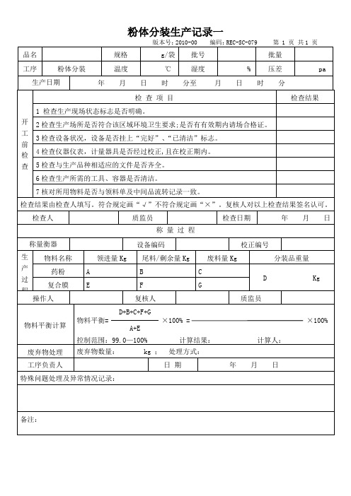
检 查 项 目
检查结果
1 检查生产现场状态标志是否明确。
2检查生产场所是否符合该区域环境卫生要求;是否有有效期内请场合格证。
3检查设备状况,设备是否挂上“完好”、“已清洁”标志。
4检查仪器仪表,计量器具是否经过校正,且在校正期内。
5检查与生产品种相适应的文件是否齐全。
6检查生产所需的工具、容器是否清洁。
7核对所用物料填写。符合规定画“√”不符合规定画“×”。复核人对以上检查结果签名认可。
检查人
质监员
检查日期
年 月 日
称 量 过 程
∽
称量衡器
设备编码
校正编号
生产过程
物料名称
领进量Kg
尾料/剩余量Kg
废料量Kg
分装品重量
药粉
A
B
C
D Kg
复合膜
E
F
G
操作人
复核人
质监员
物料平衡计算
D+B+C+F+G
物料平衡= ×100% = ×100%
废弃物处理
废弃物数量: kg ; 处理方式:
处理人:处理日期:年月日质监员:
工序负责人
日 期
年 月 日
特殊问题处理及异常情况记录:
备注:
Intel 300系列和Intel C240系列芯片集家族平台控制器总线手册 - 卷1 2版本009
Intel® 300 Series and Intel® C240 Series Chipset Family Platform Controller HubDatasheet – Volume 1 of 2Revision 009September 2021Document Number: 337347-009You may not use or facilitate the use of this document in connection with any infringement or other legal analysis concerning Intel products described herein. You agree to grant Intel a non-exclusive, royalty-free license to any patent claim thereafter drafted which includes subject matter disclosed herein.No license (express or implied, by estoppel or otherwise) to any intellectual property rights is granted by this document.Intel technologies' features and benefits depend on system configuration and may require enabled hardware, software or service activation. Learn more at , or from the OEM or retailer.No computer system can be absolutely secure. Intel does not assume any liability for lost or stolen data or systems or any damages resulting from such losses.The products described may contain design defects or errors known as errata which may cause the product to deviate from published specifications. Current characterized errata are available on request.Intel disclaims all express and implied warranties, including without limitation, the implied warranties of merchantability, fitness for a particular purpose, and non-infringement, as well as any warranty arising from course of performance, course of dealing, or usage in trade.Intel technologies' features and benefits depend on system configuration and may require enabled hardware, software or service activation. Learn more at , or from the OEM or retailer.All information provided here is subject to change without notice. Contact your Intel representative to obtain the latest Intel product specifications and roadmaps.Copies of documents which have an order number and are referenced in this document may be obtained by calling 1-800-548-4725 or visit/design/literature.htm.Intel, Core, Optane, vPro and the Intel logo are trademarks of Intel Corporation in the U.S. and/or other countries.*Other names and brands may be claimed as the property of others.© Intel Corporation. All Rights Reserved.Contents1Introduction (28)1.1About this Manual (28)1.2Overview (28)1.3PCH SKUs (29)2PCH Controller Device IDs (36)2.1Device and Revision ID Table (36)3Flexible I/O (38)3.1Overview (38)3.2Flexible I/O Implementation (38)3.2.1PCH-H (38)3.3Flexible I/O Lane Selection (39)3.3.1PCIe*/SATA Lane Selection (39)4Memory Mapping (40)4.1Overview (40)4.2Functional Description (40)4.2.1PCI Devices and Functions (40)4.2.2Fixed I/O Address Ranges (42)4.2.3Variable I/O Decode Ranges (44)4.3Memory Map (45)4.3.1Boot Block Update Scheme (47)5System Management (49)5.1Acronyms (49)5.2Overview (49)5.3Features (49)5.3.1Theory of Operation (49)5.3.2TCO Modes (50)6High Precision Event Timer (HPET) (52)6.1Overview (52)6.1.1Timer Accuracy (52)6.1.2Timer Off-load (52)6.1.3Interrupt Mapping (54)6.1.4Periodic Versus Non-Periodic Modes (55)6.1.5Enabling the Timers (56)6.1.6Interrupt Levels (57)6.1.7Handling Interrupts (57)6.1.8Issues Related to 64-Bit Timers with 32-Bit Processors (57)7Thermal Management (58)7.1PCH Thermal Sensor (58)7.1.1Modes of Operation (58)7.1.2Temperature Trip Point (58)7.1.3Thermal Sensor Accuracy (Taccuracy) (58)7.1.4Thermal Reporting to an EC (58)7.1.5Thermal Trip Signal (PCHHOT#) (59)8Power and Ground Signals (60)9Pin Straps (62)10Electrical and Thermal Characteristics (66)10.1Power Rail Absolute Maximum Ratings (66)10.2Thermal Specification (66)10.3General DC Characteristics (66)10.4AC Characteristics (82)10.4.1Panel Power Sequencing and Backlight Control (85)10.5Overshoot/Undershoot Guidelines (105)11Ballout Definition (107)128254 Timers (120)12.1Overview (120)12.1.1Timer Programming (120)12.1.2Reading from Interval Timer (121)13Audio, Voice, and Speech (123)13.1Acronyms (123)13.2AVS Subsystem Overview (123)13.3Signal Description (124)13.4Integrated Pull-Ups and Pull-Downs (126)13.5I/O Signal Planes and States (126)13.6AVS Feature Summary (127)13.6.1Intel High Definition Audio Controller Capabilities (127)13.6.2Audio DSP Capabilities (128)13.6.3Intel High Definition Audio Link Capabilities (128)13.6.4Intel Display Audio Link Capabilities (128)13.6.5DMIC Interface (128)13.6.6I2S/PCM Interface (129)13.6.7SoundWire Interface (129)14Controller Link (130)14.1Overview (130)14.2Signal Description (130)14.3Integrated Pull-Ups and Pull-Downs (130)14.4I/O Signal Planes and States (130)14.5External CL_RST# Pin Driven/Open-drain Mode Support (131)15Processor Sideband Signals (132)15.1Acronyms (132)15.2Overview (132)15.3Signal Description (132)15.4Integrated Pull-Ups and Pull-Downs (132)15.5I/O Signal Planes and States (132)15.6Functional Description (133)16Digital Display Signals (134)16.1Acronyms (134)16.2Signal Description (134)16.3Embedded DisplayPort* (eDP*) Backlight Control Signals (135)16.4Integrated Pull-Ups and Pull-Downs (135)16.5I/O Signal Planes and States (135)17Enhanced Serial Peripheral Interface (eSPI) (137)17.1Acronyms (137)17.2Overview (137)17.3Signal Description (137)17.4Integrated Pull-Ups and Pull-Downs (138)17.5I/O Signal Planes and States (138)17.6Functional Description (138)17.6.1Features (138)17.6.2Protocols (138)17.6.3WAIT States from eSPI Slave (139)17.6.4In-Band Link Reset (139)17.6.5Slave Discovery (139)17.6.6Flash Sharing Mode (140)17.6.7Channels and Supported Transactions (140)18General Purpose Input and Output (GPIO) (146)18.1Acronyms (146)18.2Overview (146)18.3Signal Description (147)18.4Functional Description (155)18.4.1GPIO Voltage (155)18.4.2Programmable Hardware Debouncer (156)18.4.3Integrated Pull-ups and Pull-downs (156)18.4.4GPPJ_RCOMP_1P8 Signal (156)18.4.5Interrupt / IRQ via GPIO Requirement (156)18.4.6SMI#/SCI and NMI (156)18.4.7Timed GPIO (156)18.4.8GPIO Blink (BK) and Serial Blink (SBK) (157)18.4.9GPIO Ownership (157)19Intel® Serial I/O Generic SPI (GSPI) Controllers (158)19.1Acronyms (158)19.2Overview (158)19.3Signal Description (158)19.4Integrated Pull-Ups and Pull-Downs (159)19.5I/O Signal Planes and States (159)19.6Functional Description (159)19.6.1Features (159)19.6.2Controller Overview (160)19.6.3DMA Controller (160)19.6.4Reset (161)19.6.5Power Management (161)19.6.6Interrupts (162)19.6.7Error Handling (162)20Intel® Serial I/O Inter-Integrated Circuit (I2C) Controllers (163)20.1Acronyms (163)20.2References (163)20.3Overview (163)20.4Signal Description (163)20.5I/O Signal Planes and States (164)20.6Functional Description (164)20.6.1Features (164)20.6.2Protocols Overview (164)20.6.3DMA Controller (165)20.6.4Reset (166)20.6.5Power Management (166)20.6.6Interrupts (167)20.6.7Error Handling (167)20.6.8Programmable SDA Hold Time (167)21Gigabit Ethernet Controller (168)21.1Acronyms (168)21.2References (168)21.3Overview (168)21.4Signal Description (168)21.5Integrated Pull-Ups and Pull-Downs (169)21.6I/O Signal Planes and States (169)21.7Functional Description (170)21.7.1GbE PCI Express* Bus Interface (171)21.7.2Error Events and Error Reporting (172)21.7.3Ethernet Interface (172)21.7.4PCI Power Management (173)22Interrupt Interface (174)22.1Acronyms (174)22.2Overview (174)22.3Signal Description (174)22.4Integrated Pull-Ups and Pull-Downs (174)22.5I/O Signal Planes and States (174)22.6Functional Description (175)22.6.18259 Interrupt Controllers (PIC) (178)22.6.2Interrupt Handling (179)22.6.3Initialization Command Words (ICWx) (180)22.6.4Operation Command Words (OCW) (181)22.6.5Modes of Operation (181)22.6.6Masking Interrupts (183)22.6.7Steering PCI Interrupts (184)22.7Advanced Programmable Interrupt Controller (APIC) (D31:F0) (184)22.7.1Interrupt Handling (184)22.7.2Interrupt Mapping (184)22.7.3PCI/PCI Express* Message-Based Interrupts (184)22.7.4IOxAPIC Address Remapping (185)22.7.5External Interrupt Controller Support (185)22.8Serial Interrupt (185)22.8.1Start Frame (186)22.8.2Stop Frame (186)22.8.3Specific Interrupts Not Supported Using SERIRQ (187)23Integrated Sensor Hub (ISH) (188)23.1Acronyms (188)23.2References (188)23.3Overview (188)23.4Signal Description (189)23.5Integrated Pull-Ups and Pull-Downs (189)23.6I/O Signal Planes and States (190)23.7Functional Description (190)23.7.1ISH Micro-Controller (190)23.7.2SRAM (190)23.7.3PCI Host Interface (191)23.7.4Power Domains and Management (191)23.7.5ISH IPC (191)23.7.6ISH Interrupt Handling via IOAPIC (Interrupt Controller) (192)23.7.7ISH I2C Controllers (192)23.7.8ISH UART Controller (192)23.7.9ISH GSPI Controller (193)23.7.10ISH GPIOs (193)24Low Pin Count (LPC) (194)24.1Acronyms (194)24.2References (194)24.3Overview (194)24.4Signal Description (194)24.5Integrated Pull-Ups and Pull-Downs (195)24.6I/O Signal Planes and States (195)24.7Functional Description (195)24.7.1LPC Cycle Types (195)24.7.2Start Field Definition (196)24.7.3Cycle Type/Direction (CYCTYPE + DIR) (196)24.7.4Size (197)24.7.5SYNC Timeout (197)24.7.6SYNC Error Indication (197)24.7.7LFRAME# Usage (198)24.7.8I/O Cycles (198)24.7.9LPC Power Management (198)24.7.10Configuration and PCH Implications (198)25PCH and System Clocks (199)25.1Overview (199)25.2PCH ICC Clocking Profiles (199)25.3PCH ICC XTAL Input Configurations (200)25.4Signal Descriptions (200)25.5I/O Signal Pin States (201)25.6General Features (202)26PCI Express* (PCIe*) (203)26.1Overview (203)26.2Signal Description (204)26.3I/O Signal Planes and States (204)26.4PCI Express* Port Support Feature Details (204)26.4.1Intel® Rapid Storage Technology (Intel® RST) for PCIe* Storage (206)26.4.2Interrupt Generation (206)26.4.3PCI Express* Power Management (207)26.4.4Dynamic Link Throttling (208)26.4.5Port 8xh Decode (209)26.4.6Separate Reference Clock with Independent SSC (SRIS) (209)26.4.7Advanced Error Reporting (210)26.4.8Single- Root I/O Virtualization (SR- IOV) (210)26.4.9SERR# Generation (210)26.4.10Hot-Plug (210)26.4.11PCI Express* Lane Polarity Inversion (211)26.4.12PCI Express* Controller Lane Reversal (211)26.4.13Precision Time Measurement (PTM) (212)27Power Management (213)27.1Acronyms (213)27.2References (213)27.3Overview (213)27.4Signal Description (213)27.5Integrated Pull-Ups and Pull-Downs (216)27.6I/O Signal Planes and States (216)27.7Functional Description (218)27.7.1Features (218)27.7.2 PCH and System Power States (218)27.7.3System Power Planes (220)27.7.4SMI#/SCI Generation (220)27.7.5C-States (223)27.7.6Dynamic 24 MHz Clock Control (223)27.7.7Sleep States (224)27.7.8Event Input Signals and Their Usage (228)27.7.9ALT Access Mode (232)27.7.10System Power Supplies, Planes, and Signals (233)27.7.11Legacy Power Management Theory of Operation (238)27.7.12Reset Behavior (238)28Real Time Clock (RTC) (241)28.1Acronyms (241)28.2Overview (241)28.3Signal Description (241)28.4I/O Signal Planes and States (242)28.5Functional Description (242)28.5.1Update Cycles (243)28.5.2Interrupts (243)28.5.3Lockable RAM Ranges (243)28.5.4Century Rollover (243)28.5.5Clearing Battery-Backed RTC RAM (244)28.5.6External RTC Circuitry (244)29Serial ATA (SATA) (245)29.1Acronyms (245)29.2References (245)29.3Overview (245)29.4Signals Description (245)29.5Integrated Pull-Ups and Pull-Downs (249)29.6I/O Signal Planes and States (249)29.7Functional Description (250)29.7.1SATA 6Gb/s Support (250)29.7.2SATA Feature Support (250)29.7.3Hot-Plug Operation (250)29.7.4Intel® Rapid Storage Technology (Intel® RST) (250)29.7.5Intel® Rapid Storage Technology enterprise (Intel® RSTe)- for Server/Workstation Only (252)29.7.6Power Management Operation (253)29.7.7SATA Device Presence (255)29.7.8SATA LED (256)29.7.9Advanced Host Controller Interface (AHCI) Operation (256)29.7.10Enclosure Management (SGPIO Signals) (257)30System Management Interface and SMLink (260)30.1Acronyms (260)30.2References (260)30.3Overview (260)30.4Signal Description (260)30.5Integrated Pull-Ups and Pull-Downs (261)30.6I/O Signal Planes and States (261)30.7Functional Description (261)31Host System Management Bus (SMBus) Controller (262)31.1Acronyms (262)31.2References (262)31.3Overview (262)31.4Signal Description (262)31.5Integrated Pull-Ups and Pull-Downs (262)31.6I/O Signal Planes and States (263)31.7Functional Description (263)31.7.1Host Controller (263)31.7.2SMBus Slave Interface (269)31.8SMBus Power Gating (276)32Serial Peripheral Interface (SPI) (277)32.1Acronyms (277)32.2Overview (277)32.3Signal Description (277)32.4Integrated Pull-Ups and Pull-Downs (278)32.5I/O Signal Planes and States (278)32.6Functional Description (279)32.6.1SPI0 for Flash (279)32.6.2SPI0 Support for TPM (283)32.6.3SPI1 Support for Touch Device (283)33Testability (284)33.1JTAG (284)33.1.1Acronyms (284)33.1.2References (284)33.1.3Overview (284)33.1.4Signal Description (284)33.1.5I/O Signal Planes and States (285)33.2Intel® Trace Hub (Intel® TH) (285)33.2.1Overview (285)33.2.2Platform Setup (286)33.3Direct Connect Interface (DCI) (286)33.3.1Out Of Band (OOB) Hosting DCI (287)33.3.2USB Hosting DCI.DBC (287)33.3.3Platform Setup (287)34Intel® Serial I/O Universal Asynchronous Receiver/Transmitter (UART) Controllers...28834.1Acronyms (288)34.2Overview (288)34.3Signal Description (288)34.4Integrated Pull-Ups and Pull-Downs (289)34.5I/O Signal Planes and States (289)34.6Functional Description (289)34.6.1Features (289)34.6.2UART Serial (RS-232) Protocols Overview (290)34.6.316550 8-bit Addressing - Debug Driver Compatibility (291)34.6.4DMA Controller (291)34.6.5Reset (292)34.6.6Power Management (292)34.6.7Interrupts (293)34.6.8Error Handling (293)35Universal Serial Bus (USB) (294)35.1Acronyms (294)35.2References (294)35.3Overview (294)35.4Signal Description (294)35.5Integrated Pull-Ups and Pull-Downs (297)35.6I/O Signal Planes and States (297)35.7Functional Description (298)35.7.1eXtensible Host Controller Interface (xHCI) Controller (D20:F0) (298)35.7.2USB Dual Role Support - eXtensible Device Controller Interface (xHCI) Controller(D20:F1) (298)35.7.3Supported USB 2.0 Ports (298)36Connectivity Integrated (CNVi) (299)36.1Acronyms (299)36.2References (299)36.3Overview (299)36.4Signal Description (299)36.5I/O Signal Planes and States (301)36.6Functional Description (303)37GPIO Serial Expander (304)37.1Acronyms, Definitions (304)37.2Overview (304)37.3Signal Description (304)37.4Integrated Pull-ups and Pull-downs (304)37.5Functional Description (304)38Direct Media Interface (306)38.1Acronyms (306)38.2Overview (306)38.3Signal Description (306)38.4I/O Signal Planes and States (306)38.5Functional Description (306)38.5.1Lane Reversal (306)38.5.2Polarity Inversion (306)39Private Configuration Space Target Port ID (307)39.1Overview (307)40Secure Digital eXtended Capacity (SDXC) (309)40.1Acronyms (309)40.2References (309)40.3Overview (309)40.4Signal Description (309)40.5I/O Signal Planes and States (310)40.6Functional Description (310)40.7Virtual GPIO (vGPIO) Used as Interrupt (310)Figures3-1High Speed I/O (HSIO) Lane Multiplexing in PCH-H (36)5-1TCO Compatible Mode SMBus Configuration (48)5-2Advanced TCO Mode (49)10-1PCI Express* Transmitter Eye (82)10-2PCI Express* Receiver Eye (82)10-3Panel Power Sequencing (83)10-4Clock Timing (87)10-5Measurement Points for Differential Waveforms (88)10-6I2C, SMBus/SMLink Transaction (89)10-7USB Rise and Fall Times (90)10-8USB Jitter (91)10-9USB EOP Width (91)10-10SMBus/SMLink Timeout (93)10-11Intel® High Definition Audio (Intel® HD Audio) Input and Output Timings (94)10-12 Valid Delay from Rising Clock Edge (94)10-13Valid Delay from Rising Clock Edge (95)10-14Setup and Hold Times (95)10-15Float Delay (95)10-16Output Enable Delay (96)10-17Pulse Width (96)10-18PCH Test Load (96)10-19SPI/GSPI/eSPI Timings (100)10-20Controller Link Receive Timings (101)10-21Controller Link Receive Slew Rate (101)10-22Maximum Acceptable Overshoot/Undershoot Waveform (104)11-1PCH BGA Ball Map (Top View – Upper Left) (106)11-2PCH BGA Ball Map (Top View – Upper Right) (107)11-3PCH BGA Ball Map (Top View – Lower Left) (108)11-4PCH BGA Ball Map (Top View – Lower Right) (109)17-1Basic eSPI Protocol (137)17-2eSPI Slave Request to PCH for PCH Temperature (140)17-3PCH Response to eSPI Slave with PCH Temperature (141)17-4eSPI Slave Request to PCH for PCH RTC Time (141)17-5PCH Response to eSPI Slave with RTC Time (142)20-1Data Transfer on the I2C Bus (163)24-1LPC Interface Diagram (192)25-1Integrated Clock Controller (ICC) Diagram (197)25-2PCH ICC XTAL Input Configurations (198)26-1Supported PCI Express* Link Configurations (203)26-2Generation of SERR# to Platform (208)27-1Conceptual Diagram of SLP_LAN# (234)29-1Flow for Port Enable/Device Present Bits (254)29-2Serial Data transmitted over the SGPIO Interface (257)32-1Flash Descriptor Regions (279)33-1Platform Setup with Intel® Trace Hub (284)33-2Platform Setup with DCI Connection (285)34-1UART Serial Protocol (288)34-2UART Receiver Serial Data Sample Points (289)37-1Example of GSX Topology (303)Tables1-1PCH I/O Capabilities (27)1-1Desktop PCH SKUs (27)1-2Workstation / Server PCH SKUs (28)1-3Mobile PCH SKUs (29)1-4Desktop PCH HSIO Details (30)1-5Workstation / Server PCH HSIO Details (31)1-6Mobile PCH HSIO Details (32)2-1PCH Device and Revision ID Table (34)4-1PCI Devices and Functions (38)4-2Fixed I/O Ranges Decoded by PCH (40)4-3Variable I/O Decode Ranges (43)4-4PCH Memory Decode Ranges (Processor Perspective) (43)4-5Boot Block Update Scheme (46)5-1Event Transitions that Cause Messages (48)6-1Legacy Replacement Routing (52)8-1Power Rails Descriptions PCH-H (58)9-1Pin Straps (60)10-1PCH Absolute Power Rail Maximum and Minimum Ratings (64)10-2PCH I cc3 with Integrated 1.8V VRM Mode OFF (Desktop SKUs) (64)10-3PCH I cc3 with Integrated 1.8V VRM Mode OFF (H Mobile SKUs) (66)10-4PCH I cc3 with Integrated 1.8V VRM Mode ON (Desktop SKUs) (67)10-5PCH I cc3 with Integrated 1.8V VRM Mode ON (H Mobile SKUs) (68)10-6PCH VCCPRIM_1P05 Adder per HSIO Lane (69)10-7PCH VCCPRIM_1P8 Adder with and without CNVi (69)10-8PCH VCCPRIM_3P3 Adder with and without CNVi (69)10-9Single-Ended Signal DC Characteristics as Inputs or Outputs (70)10-10Single-Ended Signal DC Characteristics as Inputs or Outputs (76)10-11Differential Signals Characteristics (77)10-12Power Rail Operational Voltage Range (79)10-13PCI Express* Interface Timings (80)10-14DDC Characteristics (83)10-15DisplayPort* Hot-Plug Detect Interface (84)10-16Clock Timings (84)10-17USB 2.0 Timing (89)10-18USB 3.1 Interface Transmit and Receiver Timings (90)10-19SATA Interface Timings (91)10-20SMBus Timings (92)10-21I2C and SMLink Timing (Sheet 1 of 2) (92)10-22Intel® High Definition Audio (Intel® HD Audio) Timing (93)10-23DMIC Timing (94)10-24LPC Timing (24 MHz) (94)10-25Miscellaneous Timings (96)10-26SPI Timings (20 MHz) (96)10-27SPI Timings (33 MHz) (97)10-28SPI Timings (50 MHz) (97)10-29SPI Touch Timings (20 MHz) (98)10-30SPI Touch Timings (33 MHz) 1.8V/3.3V (98)10-31eSPI Timings (33 MHz) (99)10-32eSPI Timings (50 MHz) (99)10-33eSPI Timings (66 MHz) (100)10-34GSPI Timings (25 MHz) (100)10-35Controller Link Receive Timings (101)10-36UART Timings (102)10-37I2S Timings - Master Mode (102)10-38I2S Timing - Slave Mode (non S0ix) (102)10-39I2S Timing - Slave Mode (S0ix) (102)10-40 3.3V Overshoot/Undershoot Specifications (103)11-1PCH BGA Ballout (110)12-1Counter Operating Modes (119)13-1Signal Descriptions (122)13-2Integrated Pull-Ups and Pull-Downs (124)13-3I/O Signal Planes and States (124)16-1Digital Display Signals (132)17-1eSPI Channels and Supported Transactions (138)17-2eSPI Virtual Wires (VW) (139)18-1GPIO Group Summary (144)18-2General Purpose I/O Signals (145)21-1GbE LAN Signals (166)21-2Integrated Pull-Ups and Pull-Downs (167)21-3Power Plane and States for Output Signals (167)21-4Power Plane and States for Input Signals (167)21-5LAN Mode Support (171)22-1Interrupt Options - 8259 Mode (173)22-2Interrupt Options - APIC Mode (174)22-3Interrupt Logic Signals (175)22-4Interrupt Controllers PIC (176)22-5Interrupt Status Registers (177)22-6Content of Interrupt Vector Byte (177)22-7Stop Frame Explanation (184)22-8Data Frame Format (185)23-1I/O Signal Planes and States (188)23-2IPC Initiator -> Target flows (190)24-1LPC Cycle Types Supported (194)24-2Start Field Bit Definitions (194)24-3Cycle Type Bit Definitions (194)24-4Transfer Size Bit Definition (195)24-5SYNC Bit Definition (195)25-1PCH ICC Clocking Profile Support (198)25-1Signal Descriptions (199)25-2I/O Signal Pin States (199)26-1Power Plane and States for PCI Express* Signals (202)26-2PCI Express* Port Feature Details (202)26-3MSI Versus PCI IRQ Actions (205)27-1General Power States for Systems Using the PCH (216)27-2State Transition Rules for the PCH (217)27-3System Power Plane (218)27-4Causes of SMI and SCI (219)27-5Sleep Types (222)27-6Causes of Wake Events (223)27-7Transitions Due to Power Failure (224)27-8Supported Deep Sx Policy Configurations (225)27-9Deep Sx Wake Events (226)27-10Transitions Due to Power Button (227)27-11Write Only Registers with Read Paths in ALT Access Mode (231)27-12PIC Reserved Bits Return Values (231)27-13SUSPWRDNACK/SUSWARN#/GPP_A13 Pin Behavior (235)27-14SUSPWRDNACK During Reset (235)27-15Causes of Host and Global Resets (237)28-1RTC Crystal Requirements (242)28-2External Crystal Oscillator Requirements (242)29-1Signals Description (243)31-1I2C Block Read (264)31-2Enable for SMBALERT# (266)31-3Enables for SMBus Slave Write and SMBus Host Events (267)31-4Enables for the Host Notify Command (267)31-5Slave Write Registers (268)31-6Command Types (268)31-7Slave Read Cycle Format (269)31-8Data Values for Slave Read Registers (270)31-9Host Notify Format (272)31-10Slave Read Cycle Format (272)31-11Data Values for Slave Read Registers (273)31-12Enables for SMBus Slave Write and SMBus Host Events (274)32-1Signal Description (275)32-2SPI0 Flash Regions (278)32-3Region Size Versus Erase Granularity of Flash Components (278)32-4Region Access Control Table (280)33-1Testability Signals (282)33-2Power Planes and States for Testability Signals (283)35-1Signal Descriptions (293)39-1Private Configuration Space Register Target Port IDs (306)40-1SD Working Modes (309)Revision HistoryRevision Number Description Revision Date 001•Initial Release April 2018002Chapter 10, Electrical CharacteristicsAugust 2018•Added note 15 in Table10-16.•Updated Table10-18 to include USB 3.1 Gen1(5 GT/s) andUSB 3.1 Gen2(10 GT/s) spec.•Updated signal names in Table10-22 and Table10-24.•Added USB 2.0 undershoot/overshoot spec in Table10-40.Chapter 11, Ballout Definition•Updated information for x4 DMI only support. Removed[7:4] lane and x8 width details.Chapter 24, Low Pin Count•Updated the LPC specification link in “References section”Chapter 26, PCI Express•Added Precision Time Measurement (PTM) detailsChapter 33, Testability•Added a note in Section33.3 stating that DCI and kernellevel debugger are mutually exclusiveChapter 38, Direct Media Interface•Updated information for x4 DMI only support. Removed[7:4] lane and x8 width details.Chapter 39, Private Configuration Space Target Port ID•Changed chapter name to “Private Configuration SpaceTarget Port ID”.•Updated Table39.1.August 2018 003Chapter 2, PCH Controller Device IDs•Updated Section2.1.•Updated Device and Revision ID table.Chapter 10, Electrical Characteristics•Updated VOH min Value in Table10-9.•Updated I2S timing specification in Table10-31, Table10-37and Table10-36.•Updated Figure10-7, Table10-24, Table10-26,Table10-27, Table10-28 and Table10-34.•Added Table10-30.Chapter 22, Low Pin Count•Updated the LPC specification link in Section24.2.•Updated the LPC Interface diagram.•Updated signal description.•Updated I/O Signal Planes and States.Chapter 25, PCH and System Clocks•Included updated ICC diagrams which show HDA_PLL andXTAL Direct Paths for Display clock generation. Also removedconditional text for CPUNSSC clock descriptions.•Added missing HM375, QM375, and CM248 details to PCHICC Clocking. Profile Support table.Chapter 26, PCI Express* (PCIe*)Corrected HM370 SKU PCIe* Controller Remapping Details.004Chapter 1, Introduction•Added Z390 details•Added C242 and C246 SKU detailsChapter 2, PCH Controller Device IDs•Added C242 and C246 SKU details in Table2-1Chapter 5, System Management•Removed “Second hard-coded timer timeout to generatereboot” from Section 5.3, “Features”•Changed Intel ME to Intel® CSMEChapter 10, Electrical and Thermal Characteristics•Updated Chapter title to “Electrical and ThermalCharacteristics”•Removed PCH Power Supply Range table•Updated Section 10.2, “Thermal Specification”•Updated Table10-1, Table10-2, Table10-3, Table10-4,Table10-5, Table10-6, Table10-9, Table10-11,Table10-12, Table10-14, Table10-15, Table10-16•Updated notes section of Table10-10•Updated notes for t108 in Table10-17•Updated Figure10-11•SPI Clock frequency updated to 50 MHz from 48MHz inTable10-28•SPI Touch Timings (17 MHz) table added Table10-29•SPI Clock frequency updated to 25 MHz from 20MHz inTable10-34•eSPI Timings added (30,48 and 60 MHz) (Table10-31,Table10-32, Table10-33).Chapter 21, Gigabit Ethernet Controller•Updated Section 21.2, “References” and Section 21.7,“Functional Description”Chapter 24, Low Pin Count (LPC)•Updated Section 24.2, “References” and Section 24.7.6,“SYNC Error Indication”Chapter 25, PCH and System Clocks•Added C242 and C246 SKU details in Table25-1•Added the signal Type for XTAL_Freq_Select in Table25-1Chapter 26, PCI Express (PCIe*)•Added Z390 SKU Figure26-1•Removed HM375, QM375, and CM248 SKUs that are nolonger supported SKUsChapter 28, Real Time Clock (RTC)•Updated Section28.5.6 with correct design guide references•Updated table note in Section28.4Chapter 32, Serial Peripheral Interface (SPI)•Updated Section 32.6.1.3.2, “Flash Descriptor CPU ComplexSoft Strap Section”•Updated Table32-4•Updated Section 32.5, “I/O Signal Planes and States”Chapter 35, Universal Serial Bus (USB)•Added C242 and C246 SKU details in Figure35-1Chapter 40, Secure Digital eXtended Capacity (SDXC)•Updated Section 40.4, “Signal Description”•Updated Section 40.5, “I/O Signal Planes and States”December 2018Revision Number Description Revision Date。
009-笔试试卷九级1套
全国中小学语文综合能力测评 九级试卷全国中小学语文综合能力测评 九级试卷第四部分 阅读写作〇--〇--〇请 认 真 填 写 下 面 信 息 *请按考号顺序收卷〇--〇--〇考生姓名:考生性别:准考证号:证件号码:报考级别:综合得分:(时间90分钟,满分60分)密封线内不得答题一、阅读能力(20分)2. 解释下列句子中加点的词。
(2分)(1)恐托付不效 ( ) (2)臣非不自惜也( ) (3)故临崩寄臣以大事也( ) (4)故五月渡泸,深入不毛( )3. 用现代汉语写出下列句子的意思。
(2分) (1)此臣所以报先帝而忠陛下之职分也。
_______________________________________________________________________________ (2)臣受命之日,寝不安席,食不甘味。
_______________________________________________________________________________4. 甲、乙两文都提出了蜀军北伐的有利条件,分别找出有关句子。
(2分)甲文中的有关句子:____________________________________________________________ 乙文中的有关句子:____________________________________________________________5. 甲、乙两段文字在内容上都写到了哪两层意思?分别概括回答。
(2分)_______________________________________________________________________________ _______________________________________________________________________________诚实是一块画布①没有人拒绝才华。
- 1、下载文档前请自行甄别文档内容的完整性,平台不提供额外的编辑、内容补充、找答案等附加服务。
- 2、"仅部分预览"的文档,不可在线预览部分如存在完整性等问题,可反馈申请退款(可完整预览的文档不适用该条件!)。
- 3、如文档侵犯您的权益,请联系客服反馈,我们会尽快为您处理(人工客服工作时间:9:00-18:30)。
目录
1 编制依据
2 轴封系统吹扫措施
3 注意事项
4 工业减温减压器吹扫措施
5 注意事项
1.编制依据
1.1《汽机本体轴封及门杆漏汽管道安装图》
1.2《电力建设施工及验收技术规范》管道篇DL5031-94
1.3《火电施工质量验收及评定标准》管道篇2000版
1.4《电力建设安全工作规程》
2.轴封系统吹扫措施
2.1除氧器调试结束、整定安全门工作结束保持除氧器汽平衡压力0.4Mpa、汽平衡温度200~300℃。
2.2将供前后轴封管道法兰打开,接临时吹扫管线阀门,排大气吹扫每次持续5~10分钟,连续吹扫不得少于两次。
2.3在轴封回汽至轴封冷却器接临时吹扫管线,排大气每两次间隔30分钟以上使管道冷却。
2.4轴封供汽管道蒸汽吹扫检验不安装靶板,直接从管道排汽口目测观察,排出的蒸汽清洁、无杂物为合格。
2.5.要求吹管临时管道内径大于或等于原正式管道内径。
2.6临时管道最低点装置临时疏水,疏水单独引至厂房外安全地带排放一二次疏水应分开。
2.7吹扫步骤及临时系统图附后。
3.注意事项
3.1吹扫前后汽封时,汽封进汽处法兰应打开,汽机本体轴封处法兰加装堵板。
3.2吹扫至本体扩容器管路时,扩容器进口处法兰打开,均压箱至前后轴封门关闭。
3.3所有吹扫结束后,恢复所有系统连接,并清理凝汽器。
3.4临时管道出口处应避开汽轮机设备接口及相关电气、热工元件。
并在安全无人的地方,附近应架设警告牌,并专人负责,以防在吹扫过程中,发生人身烫伤事故。
4.工业减温减压器吹扫措施
4.1主蒸气吹扫、锅炉整定安全门工作结束保持主汽压力3~4Mpa,主汽温度200~300℃。
4.2将工业减温减压器出口门打开,经工业供汽管吹扫至A列厂房外,吹扫每次持续5~10分钟,连续吹管不得少于两次,排大气每两次间隔一定时间使管道冷却,吹扫直到管道排汽口目测观察清洁为止。
4.3吹扫步骤及系统图附后。
5.注意事项
5.1工业减温减压器吹扫时,压力调整门必须全开,减温减压器疏水门、排大气门关闭。
5.2吹扫时,减温减压器减温水管所有阀门关闭,必要时要在进水法兰加装盲板。
5.3吹扫时,减温减压器流量孔板必须拆除。
5.4所有吹扫结束后,恢复所有系统连接。
5.5在吹扫管道出口处应加装弯头并在安全无人的地方,附近应架设警告牌,并专人负责,以防在吹扫过程中,发生人身烫伤事故。
门杆漏汽 除氧器汽平 汽机本体轴封门杆漏汽管道系统图
除氧器加
门杆漏汽 除氧器汽平 第一阶段蒸汽吹扫系统
除氧器加
第二阶段蒸汽吹扫系统
门杆漏汽除氧器汽平除氧器加
第三阶段蒸汽吹扫系统
门杆漏汽除氧器汽平
除氧器加
第四阶段蒸汽吹扫系统门杆漏汽
除氧器汽平除氧器加
第五阶段蒸汽吹扫系统
门杆漏汽除氧器汽平除氧器。
