DCS-4500安装手册
4500韦伯触摸屏软件调试说明书
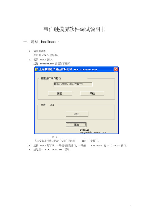
韦伯触摸屏软件调试说明书一、烧写bootloader1.需要的硬件并口的JTAG烧写器。
2.安装JTAG驱动。
运行armzone.exe 出现如下界面图1.点击安装并行端口驱动“安装”和安装0CX “安装”。
3.连接JTAG烧写线。
一端接电脑的并口,一端接LMD4500的J1(JTAG)接口。
4.烧写第一BOOTLOADER程序。
图25.点击nboot1st.bat.出现如下界面。
图3.注意红框的部分,如果和里面的内容不同,请检查驱动是否安装好。
JTAG线是否连接好,LMD4500 是否上电。
6.选择K9S1208 prog 即输入”0”。
出现下图界面。
图47.选择K9S1208 Program 即选择“0”.出现如下界面图58.输入block number 是“0“.出现如下界面图69.等烧写完之后出现如下界面。
图79.输入“2“结束第一个bootloader的烧写。
10.第二个bootloader的烧写。
运行“nboot2nd.bat “出现的界面如图 3.输入”0“之后出现图4界面。
再输入”0“之后出现图5界面。
此时要注意输入的block number 是”2“.然后出现图6界面。
烧写完成之后出现图7界面。
输入”2“结束烧写。
11.第三个bootloader的烧写。
运行“QT2440_Amon.bat “出现的界面如图 3.输入”0“之后出现图4界面。
再输入”0“之后出现图5界面。
此时要注意输入的block number 是”8“.然后出现图6界面。
烧写完成之后出现图7界面。
输入”2“结束烧写。
二、烧写NK1.运行DNW .出现如下界面:图1.2.连接串口线,一端接电脑的串口,一端接板子的P3.点击Serial Port 菜单的connect,出现如下界面图2.3.板子上电后,在DNW界面中出现“*”后输入“u”。
图3.图4.4.插入USB线,后按空格键,出现如下界面。
图5.5.选择1,按回车后界面如下:图6.6.选择USB Port—>Transmit ,找到nk.nb0。
DCS-4500系列交换机安装手册

图 1-5 DCS-4500-10C 交换机前面板 DCS-4500-28T 交换机的前面板上有 24 个 10/100/1000Base-T 端口,2 个 Combo 端 口(2 个 RJ-45 和 2 个 SFP 端口),2 个 SFP 光口,1 个 Console 端口和 32 个 LED 指示 灯。 DCS-4500-28T 交换机的前面板如下图所示:
DCS-4500 系列交换机包括如下 4 款:
DCS-4500-10C 交换机:
图 1-1 DCS-4500-10C 交换机示意图 DCS-4500-28T 交换机:
图 1-2 DCS-4500-28T 交换机示意图 DCS-4500-28T-POE 交换机:
1-1
DCS-4500 系列交换机安装手册
1-2
DCS-4500 系列交换机安装手册
1.3 产品外观
第 1 章 产品介绍
1.3.1 产品前面板
DCS-4500-10C 交换机的前面板上有 8 个 10/100/1000Base-T 端口,2 个 Combo 端口 (2 个 RJ-45 和 2 个 SFP 端口),1 个 Console 端口,1 个 USB 端口、14 个 LED 指示灯 和 1 个 220V 交流电源插座。
端口 link 成功,处在 10M、100M 或 1000M 的连接状态 端口 link 成功,并收发数据 端口没有 link 成功 端口 link 成功,处在 10M、100M 或 1000M 的连接状态 端口 link 成功,并收发数据 端口没有 link 成功
图 1-14 DCS-4500-28T 示意图
1
DCS-4500 系列交换机安装手册
EMC_FC4500安装与配置
EMC FC4500安装与配置一:准备工作硬件准备:RS6000主机F85EMC FC4500存储阵列LP8000光纤卡2块LC-LC光纤线两条(光纤线的类型要视SP和光纤卡的接口而定)Null Modem串口线(不能用标准串口线代替)带COM口的PC(不能使用USB转COM口)软件准备:NA VIAGENT 6.7 for AIXNA VICLI 6.7 for AIXNA VIAGENT 5.1 for PCLP8000的驱动程序:CLARiiON.fcp.4.0.5.0 ,CLARiiON.lp8000Navisphere Manager 5.3 for NT & W2K网络环境:F85:192.68.0.4 PC:192.168.0.112FC4500_spa:192.168.0.10, FC4500_spb:192.168.0.20二:RS6000主机安装LP8000光纤卡在RS6000主机上安装两块LP8000光纤卡和驱动程序,安装驱动之后可以看到两块光纤卡。
三:FC4500的设置FC4500的一些基本参数例如IP地址,网关,TTY等是可以通过串口用超级终端来进行设置的。
用Null Modem串口线分别连接FC4500 SP上的COM口和PC的COM口,并把超级终端进行如下设置:点击确定,进行连接.进入EMC 的FCLI命令界面,如图所示:FCLI命令行有很多的基本命令可以用来显示,设置和修改FC4500的基本参数在这里我简单的介绍以下几个命令getlog命令# 获取sp的日志文件getwwn命令#获得串口所连接的SP光纤端口的WWN地址。
由于我们是用主机直接连接fc4500,所以可以不用理睬SP的WWN地址,但在连接光纤交换机并配置zoning 的时候,就需要获得SP光纤端口的WWN地址。
举例:fcli> getwwnCurrent NODE world wide name : 50.6.1.60.fb.17.23.cfCurrent PORT world wide name : 50.6.1.68.fd.17.23.cfsetcon/con 命令#set/display console TTY parameters举例:fcli> setconBaud Rate: 9600Parity: NONE举例:fcli> help setconUsage: setcon -hsetcon <options>options:-b <#> set the console baud rate. 1200/2400/4800/9600.19200 available on sauna only-d reset the console to the default values.-p <#> set the consol parity. 0/1/2 0-none, 1-odd, 2-evensetlan命令#显示并更改sp的lan信息举例:fcli> setlanLAN Configuration: SP B LOOP ID 0x0 (0.)Ethernet Address : 08:00:3e:2f:76:2aIP Address : 192.168.0.20Subnet Mask : 255.255.255.0Broadcast Address : 192.168.0.255Default Gateway : 192.168.0.1SP Host Name : fc4500_spbTrusted Host List: (Maximum 6 Hosts)1. IP Address : 192.168.0.112 Subnet Mask : 255.255.255.02. IP Address : 192.168.0.4 Subnet Mask : 255.255.255.0举例:fcli> help setlansetlan/sl - configure the lan settingsUsage: setlan -hsetlansetlan <options>options:-ip <IP address> IP address of this SP-subnet <subnet mask> Subnet mask of this SP-gateway <gateway address> Gateway address of this SP-broadcast <broadcast address> Broadcast address of this SP-hostname <host name> Host name of this SP-ath <IP address><subnet mask> Add a trusted host-dth <IP address> Delete a trusted hostls命令#Logical Unit Summary:fcli> lsRaid Dflt. UnitLUN Group Owner Type Capacity Cache State Frus--- ----- ----- ------ -------- ----- ------- ------------------0 0 SP-B RAID-5 1.0 GB RW- ENA 0 1 21 0 SP-B RAID-5 1.0 GB RW- ENA 0 1 22 0 SP-B RAID-5 1.0 GB RW- ENA 0 1 23 0 SP-A RAID-5 1.0 GB RW- RDY 0 1 24 0 SP-A RAID-5 100 MB RW- RDY 0 1 2setport命令# allow front end fiber ports to be enabled or disabledfcli> help setportUsage: setport -hsetport <options>options:-a <on/off> enable/disable port a-b <on/off> enable/disable port b四:EMC存储系统进行管理的两中方式从用户的角度来说, 存在两种界面对存储系统进行管理: CLI 和GUI。
DMA 4500 安装与操作-中文

14
操作验证和运行验证
2.3 方法的设置
一个方法是由以下项组成: measuring temperature, display settings, printer and memory configuration, measurement settings and control settings for the optional sample changer. 不同的名字命名不同的方法,一共可以设置10个方法。
3
安装规范
1.3 仪器的安装
1.3.1 电源的要求只要和当地的电压和仪器的要求一致就可以了
DMA不要求任何特殊安装条件。其安装条件只须达到普通实验室条件。
1.3.2为了保证温度的稳定性,请勿将其放置在加热器旁,空调旁,阳光直射下 。 1.3.3 环境要求
室内使用湿度10~90%,温度15~35 ℃/59~95℉。
6
安装规范
1.3.6 将另一个孔安装带有空气管的适配器
7
安装规范
1.3.7 密闭性测试:
用空的针筒插入适配器,用拇指按住第二个孔,然后往外拉至3到4毫升的体积,到把手 松开时,可以看到针筒又恢复到了原来的零位。
8
安装规范
1.3.8 干燥空气泵的正确连接和使用
如果周围空气较潮湿且测量温度低于环境温度时 ,测量池内可能出现冷凝堵塞。这将导致校正和 测量错误。而测量池冷凝阻塞将损坏电路。将一 个干燥筒连接到DMA后部的“DRY AIR PUMP”干 燥空气泵接口,干燥筒可向彻底干燥的测量池提 供干燥空气,从而防止测量池内出现冷凝。
在density check 显示“NOT OK”时(see 2.4)
21
操作验证和运行验证
清洗
DCS系统安装(完整资料).doc

【最新整理,下载后即可编辑】目录一、适用范围----------------------------------------------------------2二、编制依据----------------------------------------------------------2三、主要施工机具----------------------------------------------------2四、施工安排-----------------------------------------------------------3五、DCS安装调试工艺---------------------------------------------3六、DCS调试---------------------------------------------------------51、DCS硬件测试----------------------------------------------------------52、DCS软件测试---------------------------------------------------------63、DCS系统调试---------------------------------------------------------7七、施工要求及注意事项---------------------------------------------8一、使用范围本规程适用于龙口嘉元东盛热电一期工程的集散型控制系统。
二、编制依据1、煤炭工业部济南设计研究院设计的电气施工图纸;2、《电力建设施工及验收技术规范》SDJ279-90;3、《工业自动化仪表工程施工及验收规范》GBJ93-86 ;4、《建筑与建筑群组合布线系统工程及验收规范》CECS89:97;三、主要施工机具1、搬运吊装机具:汽车吊。
DCS-4500系列全千兆智能安全接入交换机彩页
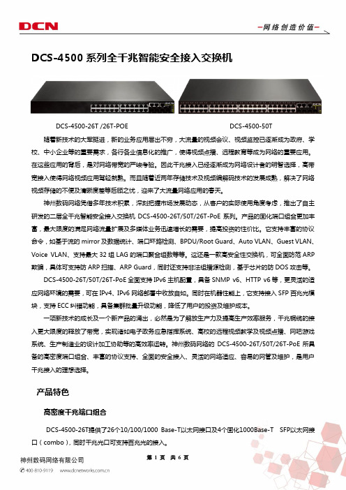
DCS-4500系列全千兆智能安全接入交换机DCS-4500-26T /26T-POE DCS-4500-50T 随着新技术的大军挺进,新的业务应用层出不穷,大流量的视频会议、视频监控已逐渐成为政府、学校、中小企业等的重要需求,各行各业信息化的推广,使得视频点播、远程教育等成为网络的重要应用。
在这些应用的背后,是对网络带宽的严峻考验。
因此千兆接入已经逐渐成为网络设计者的明智选择,高带宽接入使得网络视频应用驾轻就熟。
而且随着近两年存储技术及视频编解码技术的发展成熟,解决了网络视频存储的不便及清晰度差等后顾之忧,迎来了大流量网络应用的春天。
神州数码网络凭借多年技术积累,深刻把握市场发展动态,从客户的实际使用角度考虑,推出了自主研发的二层全千兆智能安全接入交换机DCS-4500-26T/50T/26T-PoE系列。
产品的固化端口组合更加丰富,最大限度的满足网络流量扩展及多媒体业务迅速增长的需要,提高投资的性价比。
它支持丰富的协议命令,如基于流的mirror及数据统计、端口环路检测、BPDU/Root Guard、Auto VLAN、Guest VLAN、Voice VLAN、支持最大32组LAG的端口聚合组数等等。
这还是一款高安全性交换机,可全面防范ARP 欺骗,具体可支持防ARP扫描、ARP Guard,同时还支持非法组播源检测,基于芯片的防DOS攻击等。
DCS-4500-26T/50T/26T-PoE全面支持IPv6主机配置,具备SNMP v6、HTTP v6等,更灵活的适应网络环境的需要,可在IPv4、IPv6网络部署中收放自如。
同时在机器性能上,它支持接入SFP百兆光模块,支持ECC纠错功能,具备集群批量升级功能,降低了用户的投资及维护成本。
一项新技术的成长及一个新产品的涌出,必然是为了解放生产力及提高生产效率服务,千兆铜缆的接入更大限度的释放了带宽,实现诸如电子政务应急指挥系统、高校的远程视频教学及视频点播、网吧游戏系统、生产制造业的设计加工协助等的高效率运转。
DCS-4500安装手册

丰富灵活Leabharlann 接口类型DCS-4500 系列交换机提供了多个固定 10/100/1000Base-T 端口、同时也提供了 SFP 形式的 COMBO 端口,丰富的端口类型方便了组网需求。
丰富的网络协议支持
DCS-4500 支持 802.1d/w/s 生成树协议,支持 802.1Q,802.1p,802.3ad,802.3x, GVRP,DHCP,SNTP 等标准。
1.1.1 产品概述................................................................................................. 1-1 1.1.2 产品特点................................................................................................. 1-1
2.2 安装准备 ..........................................................................................2-4
2.2.1 核对装箱单 ............................................................................................. 2-4 2.2.2 安装工具及材料...................................................................................... 2-4
1.3.3.1 端口指示灯说明...................................................................................... 1-4 1.3.3.2 系统状态指示灯说明.............................................................................. 1-5 1.3.4 前面板接口说明...................................................................................... 1-6
DCS-4500_基本管理操作

目录第1章交换机管理......................................................................1-11.1 管理方式.....................................................................................................1-11.1.1 带外管理.............................................................................................................1-11.1.2 带内管理.............................................................................................................1-51.1.2.1 通过Telnet管理交换机...........................................................................1-51.1.2.2 通过HTTP管理交换机...........................................................................1-71.1.2.3 通过snmp网管软件管理交换机............................................................1-91.2 CLI界面.....................................................................................................1-101.2.1 配置模式介绍...................................................................................................1-101.2.1.1 一般用户模式.........................................................................................1-111.2.1.2 特权用户模式.........................................................................................1-111.2.1.3 全局配置模式.........................................................................................1-111.2.2 配置语法...........................................................................................................1-131.2.3 支持快捷键.......................................................................................................1-131.2.4 帮助功能...........................................................................................................1-131.2.5 对输入的检查...................................................................................................1-141.2.5.1 成功返回信息........................................................................................1-141.2.5.2 错误返回信息........................................................................................1-141.2.6 支持不完全匹配...............................................................................................1-14第2章交换机基本配置..............................................................2-12.1 基本配置.....................................................................................................2-12.2 远程管理.....................................................................................................2-12.2.1 Telnet...................................................................................................................2-12.2.1.1 Telnet简介................................................................................................2-12.2.1.2 Telnet任务序列........................................................................................2-22.2.2 SSH......................................................................................................................2-32.2.2.1 SSH简介...................................................................................................2-32.2.2.2 SSH服务器配置任务序列.......................................................................2-32.2.2.3 SSH服务器配置举例...............................................................................2-42.3 配置交换机的IP地址.................................................................................2-42.3.1 配置交换机的IP地址任务序列.........................................................................2-42.4 SNMP配置...................................................................................................2-62.4.1 SNMP介绍..........................................................................................................2-62.4.2 MIB介绍..............................................................................................................2-72.4.3 RMON介绍.........................................................................................................2-82.4.4 SNMP配置..........................................................................................................2-82.4.4.1 SNMP配置任务序列...............................................................................2-82.4.5 SNMP典型配置举例........................................................................................2-102.4.6 SNMP排错帮助................................................................................................2-122.5 交换机升级...............................................................................................2-122.5.1 交换机系统文件...............................................................................................2-122.5.2 BootROM模式升级..........................................................................................2-132.5.3 FTP/TFTP升级.................................................................................................2-152.5.3.1 FTP/TFTP简介......................................................................................2-152.5.3.2 FTP/TFTP配置......................................................................................2-162.5.3.2.1 FTP/TFTP配置任务序列...........................................................2-162.5.3.3 FTP/TFTP配置举例..............................................................................2-182.5.3.4 FTP/TFTP排错帮助..............................................................................2-212.5.3.4.1 FTP排错帮助..............................................................................2-212.5.3.4.2 TFTP排错帮助............................................................................2-22第3章集群网管配置..................................................................3-13.1 集群网管介绍.............................................................................................3-13.2 集群网管基本配置.....................................................................................3-13.3 集群网管举例.............................................................................................3-33.4 集群网管排错帮助.....................................................................................3-4第1章 交换机管理1.1 管理方式用户购买到交换机设备后,需要对交换机进行配置,从而实现对网络的管理。
00_DCS-4500手册装帧

DCS-4500系列交换机手册手册版本:v1.5.8神州数码网络(北京)有限公司地址:北京市海淀区上地九街9号 100085 网址: 手册简介本手册由三本分手册组成:《DCS-4500安装手册》、《DCS-4500系列交换机操作手册》、《DCS-4500系列交换机命令手册》。
手册内容简介《DCS-4500安装手册》介绍DCS-4500系列交换机硬件结构、功能特点、安装方法。
《DCS-4500系列交换机操作手册》01_基本管理操作交换机的配置管理方式和对应的基本配置,包括带外管理、SNMP管理、telnet管理、web管理,软件升级方法,集群网管配置。
02_端口操作以太网端口、端口隔离、端口汇聚的操作以及JUMBO的配置。
03_VLAN和MAC地址操作VLAN、private VLAN、GVRP、QinQ、动态VLAN、Voice VLAN 的配置。
MAC地址表配置,包括MAC地址绑定和MAC地址过滤。
04_MSTP操作STP、MSTP的配置。
05_QOS操作及基于流的重定向COS、TOS、DSCP优先级配置,数据分类和转发策略的配置和使用。
基于流的重定向操作。
06_三层转发及ARP操作管理Vlan接口配置,ARP的配置。
防ARP扫描配置以及ARP GUARD配置。
07_DHCP及相关操作DHCP配置,DHCP Snooping配置以及DHCP option82配置。
08_组播协议操作IGMP Snooping、组播VLAN、IPV4组播、DCSCM(受控组播)以及MLD Snooping的配置和使用。
09_安全功能操作IP ACL、扩展的IP ACL、MAC ACL、MAC-IP ACL、IPv6 ACL 的配置,802.1x协议的配置,端口、VLAN中MAC、IP数量限制功能配置,防Dos攻击特性、TACACS+配置。
AM配置。
10_可靠性操作MRPP的配置。
11_流量监控操作镜像、sFLOW的配置。
DCS系统安装调试方案
DCS系统安装调试方案1. 简介DCS系统(分散控制系统)是一种用于监控和控制生产过程的自动化系统。
本文档将提供DCS系统的安装和调试方案。
2. 安装准备在进行DCS系统的安装之前,请确保以下准备工作已完成:- 设备选型和采购:根据需要选择合适的DCS设备,并进行采购。
- 建设环境准备:确保安装场所符合DCS系统的要求,包括电力供应、通风、地面支撑等。
- 网络规划:为DCS系统建立网络连接,确保各个设备可以正常通信。
- 安装团队组建:组建安装团队,包括设备供应商的技术人员和本地工程师。
3. 安装流程DCS系统的安装流程一般如下:1. 硬件安装:根据设备供应商提供的安装手册,将各个设备按要求进行安装,包括传感器、控制器、操作面板等。
2. 网络连接:按照网络规划的要求,将各个设备连接起来,确保网络通信正常。
3. 软件安装:根据设备供应商提供的软件安装手册,安装DCS 系统所需的软件。
4. 系统配置:根据具体的生产过程和要求,配置DCS系统的参数和功能。
5. 系统测试:进行系统测试,包括硬件功能测试、网络通信测试和软件功能测试等,确保DCS系统正常运行。
4. 调试方案在DCS系统安装完成后,需要进行调试以确保系统的正常运行。
调试方案包括以下几个方面:- 硬件调试:对各个设备进行调试,检查传感器的准确性和控制器的响应速度等。
- 网络调试:检查网络连接是否正常,确保各个设备之间可以正常通信。
- 软件调试:对DCS系统的软件进行调试,确保各个功能正常运行,并进行参数调整。
- 系统整体调试:对整个DCS系统进行综合调试,模拟实际生产过程,检查系统的稳定性和可靠性。
5. 系统验收在DCS系统的安装和调试完成后,需要进行系统验收。
系统验收主要包括以下几个方面:- 功能验收:对DCS系统的各个功能进行验证,确保符合用户的要求。
- 性能验收:对系统的性能进行测试,包括响应速度、数据准确性等指标的检查。
- 可靠性验收:对系统的可靠性进行评估,包括容错性、故障恢复等方面的测试。
4500各模块
1范围本规程主要适用于3500系统硬件、软件。
硬件系统包括:3500系统构成、各种卡件、系统电源组成等。
软件系统包括组态软件。
2.检修的一般规定2.1.1 检修项目、间隔及停用期间的规定2.1.1.1 每6个月用防静电的真空吸尘器清除以下部件的灰尘:卡件、卡件安装单元、风扇组件、电源装置2.1.1.2 每6个月清理并紧固所有电源线和接地线2.1.1.3停用期间,应作电源故障切换试验,以及电源电缆绝缘测试 3.检修前的准备2.2.1 一块万用表、一套电工组合工具、一把尖嘴钳、组合扳手、信号发生器、摇表 2.2.2 防静电真空吸尘器、防静电工具 2.2.3 检修电子电路应遵守的原则注:当安装、调试卡件时,要使用现场防静电工具(手环、接地导线装置、鳄鱼夹和防静电扩散工作面),这些工具把技术人员和静电扩散工作表面连到同一个接地点,以防静电损坏卡件。
2.2.3.1 使用静电袋。
在把装入系统前不要把它从特殊的防静电袋中取出。
卡件取出后,袋子待以后使用。
2.2.3.2 打开前把防静电袋接地。
在打开含有半导体设备的防静电袋以前,请将其与设备外壳接触一下,或者接地。
2.2.3.3 不要触摸电路。
处理卡件时,拿卡件的两侧,不要触摸电路。
2.2.3.4 防止半导体器件局部连接。
在使用前,一定要检查和卡件相连的所有设备是否完好接地。
2.2.3.5 测试设备接地。
2.2.3.6 使用现场抗静电吸尘设备。
2.2.3.7 使用接地手环。
连接接地环到电源引入盘上的接地插座,电源引入盘的接地插座和大地相连。
2.2.3.8 不要用铅笔或圆珠笔设置小开关,防止开关触电损坏,触电损坏可能导致不必要的电路板误动作。
4.系统概述我厂的汽轮机保护装置采用的是美国本特利(BENTLY)公司生产的3500保护系统,该系统是计算机化的振动信息系统,可对旋转机械和往复式运动机械的机械状态提供所需要的信息,如不平衡、不对中,轴裂纹和轴承故障等机械问题的早期判定提供可靠依据。
DCS-4500-24T(V2) 智能交换机WEB网管用户手册_V1.1

2
DCS-4500-24T(V2)1 产品简介 1.1.1 概述
产品介绍
DCS-4500-24T(V2)全千兆智能网管交换机, 提供 24 个千兆以太网端口、 4 个千兆 SFP 端口以及一个 Console 端口,支持 VLAN 划分、端口镜像、端口聚合、端口限速、802.1X、 QoS、IGMP Snooping、RSTP、LACP、DHCP Filter 等功能。可以通过命令行、Web 界 面、SNMP 多种方式进行管理。
1
DCS-4500-24T(V2) 全千兆智能网管交换机用户手册
3.14 流量控制 ___________________________________________________________ 32 3.15 端口风暴控制 _______________________________________________________ 32 第4章 状态监控 ________________________________________________________ 34
2.1 安装须知 _____________________________________________________________ 6 2.1.1 安装环境要求 ______________________________________________________ 6 2.1.2 安装操作提示 ______________________________________________________ 8 2.1.3 安全警告 _________________________________________________________ 8 2.2 安装准备 _____________________________________________________________ 9 2.2.1 核对装箱单 _______________________________________________________ 9 2.2.2 安装工具及材料 ____________________________________________________ 9 2.3 硬件安装 _____________________________________________________________ 9 2.3.1 在机架上安装交换机 ________________________________________________ 9 2.3.2 电源线连接 ______________________________________________________ 10 第3章 配置管理 ________________________________________________________ 12
简易访问4500系列轻型商业杠杆锁安装指南说明书

14500 SERIES LIGHT DUTY COMMERCIAL LEVERFour AA BatteriesPhillips ScrewdriverUtility KnifeAdhesive TapePencilTape MeasurePower DrillWith ⅜“ (10mm) Drill BitHammer/Mallet and Chisel (1”)If your latch plate needs additional depth.Bolt CuttersIf the pre-cut mounting bolts do not fit your door.What’s in the box?Interior Lock Exterior Lock2 Lever HandlesStrike PlateSpindle2 ⅜“ (60mm) and2 ¾” (70mm) latch2 Rubber Gaskets 2 KeysSupport Post Storeroom Tailpiece(Optional)Hardware SetLet’s make sure you have everything you need. If you’re missing anything, contact************************.First things first, let’s get your new lock installed.Get connected.Use the Connection Guide to getyour lock online and registered.Take control.Now your lock is fully functional andcan be managed from anywhere.23Position the template. Array STEP 1This guide assumes the door is already prepped with a 2 ⅜“ boring hole.Use the provided drilling template to mark the upper ⅜” (10mm) support hole and prepare the door for drilling. Crease the template along the dotted lines matchingthe backset for your door (2 ⅜” (60mm) or 2 ¾” (70mm)latch).View the template from the other side of the door to make sure the dotted latch line on the template is exactly centered within the boring hole opening.Once the template is aligned, tape the template in place.Mark carefully. Array STEP 2Mark the center of the upper, ⅜” (10mm) hole to be drilled using a sharp object, like a nail or a thumbtack. After marking the exterior of the door, apply the template to the interior of the door using the same methods. Make sure the holes are aligned exactly from one side of the door to the other and double check all the measurements and markings to ensure precision. Mark the center of the ⅜” (10mm) hole to be drilled fromthe other side of the door.STEP 3Drill holes.Prepare your power drill with a ⅜” (10mm) drill bit.Align the drill bit over your mark and hold the door steady. Keep the drill level and straight.Drill halfway through on the first side. Then drill the remaining half from the other side of the door. This prevents blowback damage to the door and improves accuracy.Exterior of Door Interior of DoorSince the 2 ⅛“ (54mm) boring hole already exists in this example, the lower support bolt will go through the boring hole. Only the upper 10mm hole will need to be drilled. If your door is prepped with a smaller boring hole, use the template to drill the additional lower ⅜“ support.Quick TipDoors are typically prepped with either a 2 ⅜” (60mm)or 2 ¾” (70mm) inch backset. Latches are provided foreither option.This installation will be pictured with the standard 2 ⅜”(60mm) latch. Insert the latch in the door, making surethe beveled side faces the door jamb.Exterior of DoorUse the provided screws to secure the latch in place.Quick TipMake sure the latch plate lays flush with the door. If the latch plate isnot flush in the door, draw an outline around the faceplate edge andchisel a rebate to allow the latch to lay flush with the door edge.exterior (keypad side) of the door. The spring ensures thatthe spindle remains in contact with the front of the lock.Quick TipMake sure the spindle’s spring is on the exterior side of the door.If you install the spindle with the spring on the interior side of thedoor, the lock will not work properly.STEP 6Attach the latch support post.Next, attach the latch support post to the lock. This post will be screwed into either the left or right of the center hub. The hole that you will use depends on whether your door is a left-hand or right-hand door and which size latch is used.View your latch from the exterior side of the door to determine which support post position to use, thenscrew the post into the lock.When using the 2⅜“ latch, use the inner holes closest to the center hub. If using the 2 ¾“ latch, use the outer holes. Quick TipSTEP 7Attach the gaskets.Fit the self-adhesive gaskets on the backplate of each side of the lock.Peel the white backing off the gasket and apply to the backplate of the lock. Be sure to align the edges and pull the antenna and power cable through the appropriatehole, as shown.You will see your lock’s serial and model number on the sticker on the back of the lock. Write it down or take a picture for your records. This number is needed during online registration after installation. You will also find this sticker on the lock’s box.Quick TipSTEP 8Prepare the interior lock.Remove the screw that secures the battery cover and lift the plastic cover off of the lock.Next, remove the battery pack and set them both aside.STEP 9 Measure door depth. It’s vital to use the correct mounting bolts for your door’s thickness. Two sets of different sized bolts are provided, as well as a set of bolts with cut points that can be cut to size if needed.Place one of the bolts through the mounting bolt hole on the upper, battery pack side of the lock.Hold the lock flush with the door but allow the bolt to pass along the edge of the door to gauge its length.The correct bolt should go about a ½“ past the edge of the door.½“Optional StepIf neither of the two pre-cut bolt lengths work for your door, you will need to cut the fixing bolts to the correct length. Using the same method, align the bolt along the side of the door and choose a cutting pointapproximately ½“ beyond the edge of the door.Always cut the bolts at one of the cutting points so as not to damage a thread. Use the cutting edges of pliers to crimp around the selected cutting point. If the cut produces a sharp point, use sandpaper to smooth the tip of the bolt.Quick Tip Cutting Points and Door DepthThe exterior (keypad) side of the lock has two important cables sticking out of its backplate; a power cable and a Wi-Fi antenna cable.Pass the antenna and power cable over the latch. Align the support post through the hole in the latch, andmake sure the spindle fits snugly in the lock’s hub .IMPORTANT: Be sure to pass the power cable and antenna over the latch in the door, not under.Feed the power cable and the antenna through the hole above the main spindle hole.Once the cords are inside the lock, pull them up and outof the battery pack housing.With the power cable and antenna cable coming through the lock housing, make sure the lock is level and straight.Place the fixing bolts through the interior lock mounting holes and then tighten into the front side of the lock.Both screws are needed: one at the top of the lock (through the drilled hole) and one on the bottom of thelock (below the handle going through the boring hole).Leave the top screw somewhat loose before screwing in the bottom screw. Tighten both screw back and forth until snug.Do not over tighten.Quick TipNow that the lock is mounted to the door, make sure that the lever and the latch move freely.Turn the inside handle boss to check that the spindle moves freely and the latch retracts and projects smoothly.If the lock was secured too tightly to the door, you may find that the spindle or latch sticks. To correct this, loosen the fixing bolts and adjust the position of bothsides of the lock until the spindle moves freely.Connect battery pack. Array STEP 14Insert four AA batteries (not included) into the battery pack.Connect the power cable from the lock to the battery pack by connecting the two plugs. You should hear andfeel a click when the cables connect.Position power cord. Array STEP 15Push the power plug down and to the side of the lock housing, along with the wires. This provides room for thebattery pack and the battery cover.STEP 16Insert battery pack and connect antenna.Now slide the battery pack back into the lock housing with the top wires facing out.Connect the gold Wi-Fi antenna to the battery coverplate by clicking it in place.Plug the antenna into the connector as you would plug in headphones. The connector will plug in, rather than screw in.Quick TipAttach the battery cover. STEP 17 ArraySlide the battery cover back onto the lock interior andscrew it in.Quick TipPosition the battery cover just above the lock and then slide straight down into place.Place the key cylinder cover over the key cylinder located on the exterior (keypad side) of the e the provided Allen key to loosen the small screw on the appropriate handle. The handle should point away from the latch toward the hinges.Slide the handle over the handle boss and tighten the handle screw with the Allen key.Use the provided Allen key to loosen the small screw on the other handle.Slide the handle over the handle boss and tighten the handle screw with the Allen key.Turning the interior handle should retract the latch bolt.the latch.Enter the factory default code 4321 on the keypad to unlock the lock.The keypad will flash green and the outside handle will now retract the latch. Auto lock is enabled and the lock will re-lock after 5 seconds. These settings can be configured in the portal after connecting your lock to Wi-Fi.To lock the lock, press the * button twice.PLEASE NOTE:4321 will be disabled once an additional code is added to the lock.STEP 20Test your lock.Using your lock. LockingLock the door by pressing * * on the keypad.UnlockingUnlock the door by entering a user code.Once your lock is installed and connected to Wi-Fi, you can easily control your lock, add and manage access codes with the SimpleAccess app.For a complete list of manual programming options, visit .Programming Code:User Code: 4321Auto-Lock: EnabledAuto-Lock Delay: 5 SecondsKeypad Sound: EnabledHeartbeat Interval: 1 HourCard Reader: Off (Enable with 381 or 382 function) Default SettingsBy default, and after a factory reset, your lock has the following settings:MIFARE ReaderFunctionalityThis lock is equipped with a MIFARE card reader, enabling MIFARE cards, fobs and sticky tags to be used to unlock the door. MIFARE cards will need to be enrolled in your account first and then can be assigned to access users.Visit for instructions on enrolling cards.Enabling Card ReaderThe card reader is disabled by factory default. Enabling the card reader function can either be done on the lock’s settings page after registering with your SimpleAccess account, or on the keypad with the following key commands.Enable Card/Fob Reader (Always On)Enter your(123456 by default) followedby the # button,followed by #.Enable Card/Fob Reader on Button Press Only This function turns on the card/fob reader on the lock only after a button press. This saves a bit more power than using the Always On 381 function.Enter your (123456 by default) followed by the # button,followed by #.381382Using the Card ReaderAfter adding an access user to the lock with a MIFARE credential, the credential can be used to unlock the door. This is done by holding the MIFARE credential up to the keypad of the lock.For best results, hold the card or fob in the center of the keypad (over the 5 key) within an inch of the surface.If your card or fob is not registered on the first attempt,pull your hand away momentarily and then present again.Programming Functions The keypad can be used to program lock functions. These functions can also be performed remotely from the SimpleAccess app. None of the following functions are required for setup.All keypad programming functions follow the same general steps:1. Enter your followed by the # button.2. Enter the for the desired function,followed by the # button.3. Some functions will also require you to enter afollowed by the # button.Function CodesPLEASE NOTE: Most of these settings can be updated online in the portal. After installing and connecting your lock to Wi-Fi, please register your lock and configure settings at 100: Change Programming CodeThe programming code is essentially a password. This code allows you to program the lock directly, using the keypad. By default, the code is 123456.You can change this code to any anything 4–8 digitsin length. To set a new programming code, enter the following on the lock’s keypad:Enter your current followed by the# button, 100 followed by #, and then enter yourfollowed by #.Function Codes (cont.)If successful, you will see two green flashes and hear two beeps. If an error was made, you will see a red flash.110: Add a Local User CodeLocal User Codes are intended to be used as a backup to User Codes created from the app. If internet is unavailable, you can program a code directly from the lock. Note that schedules cannot be applied to a Local User Code.Local User Codes can be 4–8 digits in length. To Add a Local User Code, enter the following on the lock’s keypad:Enter your followed by the # button, followed by #, and then enter your desiredfollowed by #.Once set, the default User Code will be disabled after your Local User Code is created.120: Delete Local User CodeIf you would like to remove your Local User Code, enter the following on the lock’s keypad:Enter your followed by the # button, followed by #, and then enter the existingfollowed by #.130: Erase ALL Local CodesIf you would like to remove ALL of your existing Local Codes, enter the following on the lock’s keypad:Enter your followed by the # button, followed by #.Function Codes (cont.)381: Enable Card/Fob Reader (Always On)This function turns on the card/fob reader on the lock. Use this if cards/fobs are being provided to access users to unlock the door.Enter yourfollowed by the # button,followed by #.382: Enable Card/Fob Reader on Button Press This function turns on the card/fob reader on the lock only after a button press. This saves a bit more power than using the Always On 381 function.Enter yourfollowed by the # button,followed by #.381382ADDITIONAL FUNCTIONS131: Erase all user codes, except 4321 default.135: Perform a factory reset. Careful, this will delete all codes, schedules and events .160: Mute keypad beeping.161: Unmute keypad beeping.270: Disable Auto Lock Mode. Your lock will automatically lock after each use.271: Enable Auto Lock Mode. Your lock will stay unlocked after being unlocked.312: Reset Wi-Fi connection. (Forget All Known Connections and Networks).320: Enter Access Point Mode to allow connection to another network.Notes 380: Turn off SmartCard reads.381: Turn on Always Scanning For Cards mode.382: Turn on Only Read Card On Keypress.390: Require # to be pressed after a user code isentered.391: Removes the requirement to enter # after a usercode.411: Enter 411* to force Wi-Fi to wake up if the lock iscurrently set to not wake up on keypress.Changes or modifications not expressly approved by the partyresponsible for compliance could void the user’s authority to operate thisequipment.This device complies with Part 15 of the FCC Rules. Operation is subjectto following two conditions: (1) This device may not cause harmfulinterference, and (2) This device must accept any interference received,including interference that may cause undesired operation.NotesNotes。
4500系列MCU管理员手册

系统管理员-MCU介绍 系统管理员-MCU的登录 系统管理员-网络设置 系统管理员-用户设置 系统管理员-终端设置 系统管理员-会议设置
1.在IE的地址栏输入 MCU的IP地址 例如:10.100.1.87 2.点击“登录”按钮, 进入到MCU登录界面。
用户列表:列出系统用户,点击 后可对相应用户进行权限及信息 的修改。
4500系列MCU—用户设置
新增用户:用户信息及权限设置。
系统管理员-MCU介绍 系统管理员-MCU的登录 系统管理员-网络设置 系统管理员-用户设置 系统管理员-终端设置 系统管理员-会议设置
4500系列MCU—终端设置
终端列表界面 点击“新增H.323”, 即可增加新的终端。
三 种 会 议 状 态
创建会议
给会议默认分 配与会成员
一般勾选上,防止 要求会议延时出现 自动结束会议
完成设定
鼠标 点击 会议 名称 我们 就进 入了 会议 的控 制界 面
对会议中的成员进行操 作,鼠标感应提示对应 按钮功能
对 会 议 进 行 分 屏
给窗口指定内容
给 与 会 成 员 发 送 文 字 信 息
首先进入的是 对网络端口A的 设置界面。
网络端口A的设定, 包括了MCU的主 机名称,IP地址设 定方式(手动人 工/DHCP)。
系统管理员-MCU介绍 系统管理员-MCU的登录 系统管理员-网络设置 系统管理员-用户设置 系统管理员-终端设置 系统管理员-会议设置
4500系列MCU—用户设置
4500系列MCU—终端设置
新增H.323终端界面
Lancer 冰淇淋机 4500系列安装说明书

6655 LANCER BLVD. • SAN ANTONIO, TEXAS 78219 USA• (210) 310-7000LINE MUST BE USED IF THE WATER SUPPLY CONTAINS ANY APPRECIABLE AMOUNT OF SILT, SAND, OR ANY OTHER DEBRIS. FAILURE TO DO SO CAN RESULT IN EQUIPMENT DAMAGE.FAILURE TO LIMIT WATER PRESSURE TO 50 PSI (3.52 KG/CM2) WILL RESULT IN IMPROPER PERFORMANCE OF THE DISPENSER - INSTALL WATER REGULATOR IF NECESSARY.THE WATER SUPPLY MUST BE PROTECTED BY MEANS OF AN AIR GAP, A BACKFLOW PREVENTION DEVICE (LOCATED UPSTREAM OF THE CO2 INJECTION SYSTEM) OR ANOTHER APPROVED METHOD TO COMPLY WITH NSF STANDARDS. A LEAKING INLET WATER CHECK V ALVE WILL ALLOW CARBONATED WATER TO FLOW BACK THROUGH THE PUMP (WHEN IT IS SHUT OFF), AND CONTAMINATE THE WATER SUPPLY. A BACKFLOW PREVENTION DEVICE MUST COMPLY WITH ASSE AND LOCAL STANDARDS. IT IS THE RESPONSIBILITY OF THE INSTALLER TO ENSURE COMPLIANCE.A SCREEN OF AT LEAST100 MESH [100 STRANDS PER 25MM (ONE INCH)] SHALL BE INSTALLED IMMEDIATELYUPSTREAM OF ALL CHECK V ALVE TYPE BACKFLOW PREVENTERS USED FOR WATER SUPPLY PROTECTION. THE SCREEN SHALL BE ACCESSIBLE AND REMOV ABLE FOR CLEANING OR REPLACEMENT.A FILTER IN THE WATER LINE MUST BE USED IF THE WATER SUPPLY CONTAINS ANY APPRECIABLE AMOUNT OF SILT,SAND, OR ANY OTHER DEBRIS. FAILURE TO DO SO CAN RESULT IN EQUIPMENT DAMAGE.DO NOT OPERATE CARBONATOR PUMP WITH WATER SUPPLY SHUT OFF.A.An adequate potable water supply must be provided. The water supply line must be at least a 3/8 inches (9.525 mm) pipe with aminimum of 20 PSI line pressure, but not exceeding a maximum of 50 PSI. Water pressure exceeding 50 PSI must be reduced to 50 PSI with a pressure regulator.1.Water pipe connections and fixtures directly connected to a potable water supply must all be sized, installed, and maintainedaccording to Federal, State, and Local laws.2.Off tastes and excessive silt, sand, or iron require that a water filter be installed in the water supplying the Carbonator. The waterfilter should be checked periodically, as required by local conditions.3.Do not connect to a heated (hot) water source or a water source supplying soft water. This will cause excessive foaming.B.The Carbonator Pump is equipped with a Strainer and a Tee on the outlet side for a plain water Valve (if required), but a water supplycontaining any appreciable quantity of silt, fine sand, or other debris requires a Filter ahead of the Unit. The Filter cartridge must be cleaned periodically, depending upon the condition of the water. Failure to do so may starve the Pump and cause it to burn out;thereby, voiding the equipment warranty.1.6INSTALLATION OF THE UNITA Inspect the counter location where the unit is to be installed. Verify that the counter is strong enough to safely support the weight ofthe unit being installed (see Section 1.3), after the cutout for the unit is made.B.Remove Splash Plate and Top Cover.C.Remove Cover Plate at rear of unit if not a “through the counter” installation.D.Connect soda and water supply lines to 3/8 inch barb fittings at the front of the unit. Check for leaks. (If dispenser is to operate withall soda valves, connect water line into one of the soda supply lines.)E.Connect syrup supply lines to the 3/8 inch barb inlet fittings at the front of the unit. Check for leaks.F.Install the ice bin drain hose; connect the 90° elbow or straight fitting underneath the unit’s base. The ice bin drain is located towardsthe front of the bin and slightly to the right. Screw the elbow or straight fitting into the cold plate; uncoil and connect the hose. Extend the hose to an open type drain.G.Connect the hose to the Drip Tray fitting, install the Drip Tray, and extend hose to open type drain.H.Both drain lines must be insulated with a closed cell insulation. Insulation must cover the entire length of the drain hose, includingfittings. The drain should be installed in such a manner that water does not collect in sags or other low points, as condensation will form.I.Install Cup Rest and Splash Plate.J.Connect Power Cord to grounded electrical outlet.K.Test Motor operation by pushing Ice Chute.L.Clean and sanitize dispenser (see Section 3).M.Fill unit approximately half full with ice. Push Chute and check for ice delivery.N.Finish filling the unit with ice and install Top Cover.O.Set brix ratio for beverage dispensing valves according to manufacturer’s instructions.1.7CONNECTING CO2WARNINGSCARBON DIOXIDE (CO2) DISPLACES OXYGEN. STRICT ATTENTION MUST BE OBSERVED IN THE PREVENTION OF CO2GAS LEAKS IN THE ENTIRE CO2AND SOFT DRINK SYSTEM. IF A CO2GAS LEAK IS SUSPECTED, IMMEDIATELY VENTILATE THE CONTAMINATED AREA BEFORE ATTEMPTING TO REPAIR THE LEAK.CO2IS A HEA VIER THAN AIR, COLORLESS, NONCOMBUSTIBLE GAS WITH A FAINTLY PUNGENT ODOR. HIGH PER-CENTAGES OF CO2MAY DISPLACE OXYGEN IN THE BLOOD, PROLONGED EXPOSURE TO CO2MAY BE HARMFUL.PERSONNEL EXPOSED TO HIGH CONCENTRATIONS OF CO2GAS WILL EXPERIENCE TREMORS WHICH ARE FOLLOWED RAPIDLY BY LOSS OF CONSCIOUSNESS AND SUFFOCATION.UNDER NO CIRCUMSTANCE SHOULD CO2PRESSURE EXCEED 80 PSI (5.6 KG/CM2). PRESSURE ABOVE THIS LIMIT WILL RESULT IN DAMAGE TO THE SYRUP PUMPS. SHOULD REMOTE SYRUP PUMPS FAIL TO OPERATE PROPERLY AT70 PSI (4.9 KG/CM2), THE CO2PRESSURE MAY BE REDUCED TO A MINIMUM PRESSURE OF60 PSI (4.2 KG/CM2), BUT NO LOWER. TO A VOID POSSIBLE PERSONAL INJURY OR PROPERTY DAMAGE, DO NOT ATTEMPT TO REMOVEIBD22, 28-0255/06IBD30, 28-0255/06。
DCS安装和网络配置
第一章软件安装和网络配置1. 概述XDPS软件分MMI软件、GTW软件和DPU软件。
升级安装时,最好先读一下第一张安装盘上的Update.txt文件,以获取有关升级的注意事项的信息。
1.1 MMI软件安装MMI软件可安装于任何能运行Windows 95/98/NT的计算机上。
一般采用工业PC或工作站,典型采用Pentium 200MHZ以上的CPU,内存要求大于等于16M,典型为64M。
MMI软件内容有网络驱动、实时数据库、MMI应用软件、VDPU软件、DPU软件影像和样例数据文件。
安装完成后,须进行网络配置和MMI应用配置,才能正常运行MMI软件。
本节只讲述MMI的安装和配置。
1.2 GTW软件安装GTW软件的运行在MMI软件之上。
GTW软件必须在安装好MMI软件后,单独安装,安装方法和内容请参见具体GTW软件的说明。
1.3 DPU软件安装DPU软件的安装和内容请参见本手册“DPU及VDPU软件”一节。
2. MMI软件的安装XDPS MMI软件是打包安装的,安装前应退出全部其它的应用程序。
安装通过向导进行,运行安装盘中的Setup.exe后,进入安装向导:先让用户选择安装目录,用户可指定任意的Windows有效目录,不存在的目录,向导会为您生成(如上右图)。
但一般采用缺省的D:\xdps2.0目录。
按“Next”继续。
右图对话框让您选择要安装的部件,列表中依次为项目数据样例文件、MMI软件、VDPU软件和DPU软件影象文件。
点击列表项,您选择/不选择该项。
一般初次安装,应选前三项,升级安装选中间二项。
最后一项,用于DPU软件的在线升级,一般只安装于工程师站上,具体说明,请参见本手册“DPU及VDPU软件”一节。
按“Next”继续;右图对话框让您选择将生成的Windows程序组名,并将出现在“开始”菜单中。
再按“Next”,就进入实质性安装。
完成后,按“Finish”结束。
安装后,在安装目录下,生成了X2bin和X2data目录,分别存放软件的执行文件和项目数据文件。
- 1、下载文档前请自行甄别文档内容的完整性,平台不提供额外的编辑、内容补充、找答案等附加服务。
- 2、"仅部分预览"的文档,不可在线预览部分如存在完整性等问题,可反馈申请退款(可完整预览的文档不适用该条件!)。
- 3、如文档侵犯您的权益,请联系客服反馈,我们会尽快为您处理(人工客服工作时间:9:00-18:30)。
2.2.1 核对装箱单 ............................................................................................. 2-4 2.2.2 安装工具及材料...................................................................................... 2-4
1.2 物理特性 ..........................................................................................1-2
1.3 产品外观 ..........................................................................................1-3
第 2 章 设备安装 .........................................................................2-1
2.1 安装须知 ..........................................................................................2-1
1.3.3.1 端口指示灯说明...................................................................................... 1-4 1.3.3.2 系统状态指示灯说明.............................................................................. 1-5 1.3.4 前面板接口说明...................................................................................... 1-6
1.2 物理特性
控制口
1个RJ-45型接口的串行控制口 交直流电源输入
交流:100 ~ 240VAC,50~60Hz 电源功耗
DCS-4500-26T:
最大50W
DCS-4500-50T: 运行温度
最大58.4W
0°C~50°C 储藏温度
1
DCS-4500 安装手册
第1章 产品介绍
1.1 产品简介
DCS-4500 系列交换机包括有两款: DCS-4500-26T:
第 1 章 产品介绍
DCS-4500-50T:源自图 1-1 DCS-4500-26T千兆交换机示意图
图 1-2 DCS-4500-50T千兆交换机示意图
1.1.1 产品概述
强大的 ACL 功能
1-1
DCS-4500 安装手册
第 1 章 产品介绍
DCS-4500 提供了完整的 ACL 策略,可根据源/目的 IP、源/目的 MAC 地址、IP 协议类 型、TCP/UDP 端口号、IP Precendence、时间范围、ToS 对数据进行分类,并使用不同的 策略进行转发。通过 ACL 策略的实施,用户可以过滤掉“冲击波”、“震荡波”、“红色代码”等 病毒包,防止扩散和冲击核心设备。支持 IEEE802.1x 基于端口的认证,为网络提供端口级 的安全保证。 配合 RADIUS 等认证机制,可有效防止非法用户侵入网络。
2.1.1 安装环境要求 ......................................................................................... 2-1 2.1.1.1 安装环境清洁度...................................................................................... 2-1 2.1.1.2 温度湿度.................................................................................................. 2-2 2.1.1.3 电源.......................................................................................................... 2-2 2.1.1.4 防静电...................................................................................................... 2-2 2.1.1.5 抗干扰...................................................................................................... 2-3 2.1.1.6 机架配置.................................................................................................. 2-3
1.3.1 产品前面板 ............................................................................................. 1-3 1.3.2 产品后面板 ............................................................................................. 1-3 1.3.3 LED指示灯说明....................................................................................... 1-3
2.1.2 安装操作提示 ......................................................................................... 2-3 2.1.3 安全警告................................................................................................. 2-3
1.1.1 产品概述................................................................................................. 1-1 1.1.2 产品特点................................................................................................. 1-1
2.3 设备安装 ..........................................................................................2-5
2.3.1 安装交换机 ............................................................................................. 2-5 2.3.2 Console 线缆连接 ................................................................................. 2-5 2.3.3 SFP收发器安装....................................................................................... 2-6 2.3.4 电缆光纤连接 ......................................................................................... 2-6 2.3.5 电源线连接 ............................................................................................. 2-7
丰富的 QoS 策略
DCS-4500 完全实现 DiffServ 模型。每个端口提供了 8 个优先级队列,可分别设定队列 带宽,支持 WRR/SP/SWRR 等调度方式。支持端口信任,可配置信任 CoS、DSCP、IP 优 先级、端口优先级,并修改数据包的 DSCP、COS 值;可根据端口、VLAN、DSCP、IP 优先级、ACL 表进行流量分类,修改数据包的 DSCP 和 IP 优先级,并指定不同的带宽,为 语音/数据/视频在同一网络中传输提供不同服务质量。
DCS-4500 安装手册
目录
目录
第 1 章 产品介绍 .........................................................................1-1
1.1 产品简介 ..........................................................................................1-1
