DBU-812智能接口单元技术使用说明书
35KV数字化变电站计算机监控系统技术规范书
**供电分公司35KV**数字化变电站计算机监控系统技术规范书(专用部分)二○一0年9月1.订购设备范围一览表供货设备(专用)规范和数量一览表**集团供电分公司35 KV ** 变电站计算机监控系统**变设备配置清单注:1、6kV电子式互感器(模拟小信号)与开关柜一起招标;2、主变高压侧电流互感器不更换,采用采集器单元将模拟信号就地转化为数字量;主变高压侧不再配置电度表;3、6KV磁控电抗器和电容器柜,保护测控装置暂时型号不确定2.工程概况项目名称:本项目为35千伏** 变电站二次系统综合自动化工程中的计算机监控系统。
计算机监控系统站控层设备配置规模需满足工程远期要求;间隔层设备按工程本期规模配置,并能方便扩充。
工程附图:附图A:变电站电气一次主接线。
3.使用条件3.1 使用环境条件3.1.1 环境温度最高温度:+ 45 ℃最低温度:-10 ℃3.1.2 环境相对湿度:≤ 90 %3.1.3 海拔高度:<1000 m3.1.3 地震烈度:度3.1.4 防护等级:IP 31 级3.2 系统运行条件3.2.1 控制与保护电源电压:DC 220V3.2.2 间隔层采用直流供电;后台机采用交流供电。
3.2.3 交流频率输入:50 Hz3.2.4 交流电压输入:应满足IEC60044-7中规定的要求,额定值为11585。
3.2.5 交流电流输入:应满足IEC60044-8中规定的要求,保护级额定值为463,测量级额定值为11585。
3.2.6 非电气量变送器输出:0—5V或4—20mA4.系统技术要求4 1系统技术要求表2:系统主要技术要求(投标人须做响应)表3 系统技术性能要求。
PDMI812D中文版本说明书-812[1]
![PDMI812D中文版本说明书-812[1]](https://img.taocdn.com/s3/m/aeca391a52d380eb62946dad.png)
图 12 1 中文显示 : 全部中文显示(默认中文显示) 2 英文显示 : 全部英文显示
非工程设计人员不得随意修改其他参数。否则将造成仪表控制错误!
第6页共6页
功 耗 : ≤5W(AC220V 线性电源供电)
●外形尺寸图
报警器开关 报警输出(可选)
Alarm On/Off
Alarm out
77
145
30
Alarm
UU Janapo
OK
ESC
PDMI 812D
220
图1
Signal
220VAC/50Hz
I
Power On/Off
O
77
连接探头 连接220VAC电源 电源开关
图 10 2、移动到设置密码位置,按“OK”键进入下一级菜单如图(11)
设置新密码 取消密码
图 11 ①设置新密码 : 设定新密码,密码由 0~9 数字构成,使用按键进行设定。调整完毕后若按“OK”键则保存当前
数值并返回菜单;若按“ESC”则放弃当前修改,返回菜单。 ②取消密码 : 取消密码输入功能 3、移动到语言选择位置,按“OK”键进入下一级菜单如图(12)
第2页共6页
●显示单元 PDMI812D
功能 : 显示露点值
上海吉纳波环境测量仪器有限公司
报警:报警点可以由客户自行设定; 报警输出为 5V 高电平信号(可选)。
变送输出:4---20mA
使用环境: 环境温度 0~50℃
相对湿度: ≤85%RH .
避免强腐蚀气体
供电电压 :AC 220V 50HZ
第1页共6页
特点
l 露点测量范围: -80 到+20 °C (-112 到+68 °F)
PCL-812PG卡说明
PCL-812PG多功能数据采集卡使用说明书第一章概述这一章介绍PCL-812PG的背景信息包括关键特性、扩展性能、产品说明书1.1绪论PCL-812PG 是IBM PC/XT/AT及其兼容机的高性能、高速、多功能数据采集卡。
整卡的详尽说明书及齐全的第三方卖主的软件支持是PCL-812PG广泛的应用于工业及实验室环境下。
主要应用于数据采集、过程控制、自动检测、工厂自动控制。
1.2关键特性。
16位单端模拟输入通道。
一个工业标准的12位逐位逼近式A/D转换器(HADC574Z)用于转换模拟量输入。
在DMA模式下最大的A/D采样速率为30KHz。
软件可编程模拟输入序列。
双极性电压+/- 5V, +/- 2.5 V, +/- 1.25V +/- 0.625 V +/- 0.3125 V。
三种A/D触发模式。
软件触发器。
可编程步测触发器。
外部脉冲触发器。
程序控制A/D转换器的数据传输,中断处理器或DMA转换。
一个Intel 8253-5可编程定时器/计数器可提供以0.5 MHz-35minutes/pulse步测输出(触发脉冲),定时器的时间基准为2 MHz。
一个16位计数器保留给用户设置应用。
两个12位单集成多极性D/A输出通道。
一路输出可由板内-5V或-10V参考电压产生0-5V 或0-10V范围的输出。
这个参考电压精度来源于A/D转换器的参考电压精度。
外部直流或交流参考电压同样也可以用于产生其它D/A 输出。
16位TTL/DTL兼容数字输入、输出通道1.3 扩展性能为了增强PCL-812PG功能,可以通过以下可选子卡来扩展其功能。
PCLD-789放大器/乘法器卡这个功能强的前置模拟信号调理卡能在一个A/D输入通道中多路传输16路信号。
高级的仪表化的放大器提供开关选择增益,分别为0.5, 1, 2, 10, 50, 100, 200, 1000或任何用户自定义。
PCLD-787八通道同步采样保持前置卡该卡允许在小于30 ns通道间采样时间偏差下进行八通道模拟信号的同步采集。
RME DMC-842数字传声器接口用户手册说明书

用户手册DMC-842数字传声器接口带有线路(Line)输出的8通道数字传声器接口8通道AES转模拟/ADAT接口AES/EBU格式和采样率转换可选的64通道MADI接口24 Bit / 192 kHz数字音频MIDI远程控制重要的安全说明 (4)概述 (5)1. 简介 (6)2. 包装清单 (6)3. 简介及主要特点 (6)4. 首次使用——快速上手 (7)4.1 控制、接口与显示 (7)4.2 快速上手 (9)5. 附件 (9)6. 产品保证 (10)7. 附录 (10)CE / FCC符合性声明 (11)使用和操作 (12)8. 前面板控制 (13)8.1 Select(选择)键和旋钮(SET) (13)8.2 Clock Section(时钟部分) (14)8.3 模拟输出 (14)8.4 Remote(遥控) (15)9. 输入通道 (15)9.1 通用 (15)9.2 Gain(增益) (15)9.3 数字幻象供电 (15)9.4 Mode 2 (16)9.5 Stereo / Inactive (16)9.6 M/S处理 (16)9.7 SRC(采样率转换器) (17)9.8 PAR (17)9.9 Sync (17)10. Setup(设置)菜单 (18)10.1 通用 (18)10.2 ID(Id,自动ID) (18)10.3 Bank(bA,库) (18)10.4 Auto ID(Au,自动ID) (19)10.5 Delay Compensation(dC,延迟补偿) (19)10.6 Follow Clock(FC,跟随时钟) (20)10.7 Word Clock Out(Co,字时钟输出) (20)10.8 Peak Hold(Ph,峰值保持) (20)10.9 Digital Output(do,数字输出) (20)10.10 Analog Output(Ao,模拟输出) (21)10.11 Gain(GA,增益) (21)10.12 Control Pulse(Cp,控制脉冲) (21)10.13 Sync Pulse(SP,同步脉冲) (21)10.14 Special(SPECIAL) (22)11. Parameter(参数)菜单 (22)11.1 通用 (22)11.2 Low Cut(Lo-Cut,低切) (23)11.3 Directivity Pattern(PAttErn,指向性图) (23)11.4 Pre-Attenuation(AttEnuAtIon,预先衰减) (23)11.5 Mute(mute,静音) (23)11.6 Peak Limiter(LImItEr,峰值限制器) (23)11.7 Command Type(ComtyPE,命令类型) (23)12. Remote Control(远程控制) (24)12.1 MIDI (24)12.2 MIDI over MADI(借助MADI的MIDI) (24)12.3 Remote Control Software(远程控制软件) (25)12.4 RS232 (26)输入和输出 (27)13. 数字输入 (28)13.1 XLR (28)13.2 D-Sub - AES/EBU Sync(同步) (28)14. 数字输出 (29)14.1 AES/EBU (29)14.2 ADAT光纤 (30)14.3 I64 MADI卡 (31)14.4不同的MADI系列可配置I64 MADI卡和ADI-642 (32)15. 模拟输出 (33)16. 字时钟 (34)16.1 字时钟输入和输出 (34)16.2 技术描述和使用 (35)16.3 布线和终止 (36)17. MIDI (36)技术参考资料 (37)18. 技术指标 (38)18.1 模拟 (38)18.2 数字输入 (38)18.3 数字输出 (40)18.4 数字 (40)18.5 MIDI (40)18.6 通用 (41)18.7 固件 (41)18.8 MADI用户比特位 (41)18.9 接口针脚 (41)19. 技术背景 (43)19.1 术语 (43)19.2 锁定(Lock)与SyncCheck(同步检查) (44)19.3 延时(Latency)与监听(Monitoring) (45)19.4 DS –双倍速 (46)19.5 QS –四倍速 (46)19.6 AES/EBU - SPDIF (47)19.7 MADI基础 (48)19.8 SteadyClock(稳定时钟) (49)20. 框图 (50)21. DMC-842的MIDI实现 (51)21.1 基本SysEx格式 (51)21.2 通知类型–命令 (51)21.3 表格 (53)重要的安全说明注意! 不要打开底盘,以防触电。
超级电源入口模块DD12及电源电筛器说明书

1IEC Appliance Inlet C14 with Filter, Fuseholder 1- or 2-pole, Line Switch 2-poleScrew-on mounting horizontal (version B)Order required accessories separatelyScrew-on mounting vertical (version A)Snap-in mountingSee below:Approvals and CompliancesC1470° CDescription- Panel mount :Screw-on from front side - 4 Functions :Appliance Inlet Protection class I , Line Switch 2-pole , Fuseholder for fuse-links 5 x 20 mm 1- or 2-pole , Line filter in standard and medical version- V-Lock notch standard- Quick connect terminals 6.3 x 0.8 mmUnique Selling Proposition- Various mounting options - Attractive flat design- Switch for highest inrush current - V-Lock cord retainingCharacteristics- Ultra-compact design. Ideal for low profile designs Aluminum case provides good shielding - All single elements are already wired- Fuse drawer meets requirements of medical standard IEC/EN 60601-1- Ideal for application with high transient loads- Suitable for use in equipment according to IEC/UL 60950Suitable for use in medical equipment according to IEC/UL 60601-1Other versions on request- Solder terminals- Fuse drawer 1-pole, plus spare fuse case - Fuse drawer 2-pole, with shorting bar - Other rocker marking - Line switch, illuminated - Line switch 1-pole - Medical version M80- Class X1- and Y1-capacitors for enhanced withstand voltageReferencesAlternative: version without line filter DD11 Alternative: version for snap-in mounting KMF Alternative: version with 2-stage filter DD14Weblinkspdf data sheet , html data sheet , General Product Information ,Distributor-Stock-Check , Accessories , Detailed request for product , Landing PageT echnical DataRatings IEC1 - 10 A @ Ta 40 °C / 250 VAC; 50 Hz Ratings UL/CSA 1 - 8 A @ Ta 40 °C / 250 VAC; 60 Hz Leakage Current standard < 0.5 mA (250 V / 60 Hz) medical < 5 µA (250 V / 60 Hz)Dielectric Strength> 1.7 kVDC between L-N > 2.7 kVDC between L/N-PE Test voltage (2 sec)Allowable Operation Tempe-rature-25 °C to 85 °CClimatic Category 25/085/21 acc. to IEC 60068-1IP-Protection from front side IP 40 acc. to IEC 60529Protection Class Suitable for appliances with protection class I acc. to IEC 61140TerminalQuick connect terminals 6.3 x 0.8 mm Panel Thickness SScrew-on mounting: max 8 mm Mounting screw torque max 0.5 Nm Snap-in: 1 mm to 3 mmMaterial: HousingThermoplastic, black, UL 94V-0appliance inlet/-outletC14 acc. to IEC 60320-1UL 498, CSA C22.2 no. 42 (for cold conditions) pin-temperature 70 °C, 10 A, Protection Class IFuseholder1 or2 pole, Shocksafe category PC2 acc. to IEC 60127-6, for fuse-links 5 x 20 mmRated Power Acceptance @ Ta 23 °C5 x 20: 2 W (1 pole)/ 1.6 W (2-pole) per polePower Acceptance @ Ta > 23°C Admissible power acceptance at higher ambient temperature see derating cur-vesLine SwitchRocker switch 2-pole, non-illuminated, acc. to IEC 61058-1 Technical DetailsLine FilterStandard and Medical Version, IEC 60939, UL 1283, CSA C22.2 no. 8 Technical DetailsMTBF> 2'000'000 h acc. to MIL-HB-217 FApprovals and CompliancesDetailed information on product approvals, code requirements, usage instructions and detailed test conditions can be looked up in Details about ApprovalsSCHURTER products are designed for use in industrial environments. They have approvals from independent testing bodies according to national and international standards. Products with specific characteristics and requirements such as required in the automotive sector according to IATF 16949, medical technology according to ISO 134485 or in the aerospace industry can be offered exclusively with customer-specific, individual agree-ments by SCHURTER.ApprovalsThe approval mark is used by the testing authorities to certify compliance with the safety requirements placed on electronic products.Approval Reference T ype: DD12Approval Logo Certificates Certification Body DescriptionVDE Approvals VDE Certificate Number: 40001522UL Approvals ULUL File Number: E72928CQC Approvals CQC CQC File Number: CQC19001211536 Product standardsProduct standards that are referencedOrganization Design StandardDescriptionDesigned according to IEC 60320-1Appliance couplers for household and similar general purposesDesigned according to IEC 60939Passive filters for suppressing electromagnetic interferenceDesigned according to IEC 60127-6Miniature fuses. Part 6. Fuse-holders for miniature fuse-linksDesigned according to IEC 61058-1Switches for appliances. Part 1. General requirements Designed according to UL 498Standard for Attachment Plugs and ReceptaclesDesigned according to UL 1283Electromagnetic interference filtersDesigned according to CSA C22.2 no. 42General Use Receptacles, Attachment Plugs, and Similar Wiring DevicesDesigned according to CSA C22.2 no. 8Electromagnetic interference (EMI) filters Application standardsApplication standards where the product can be usedOrganization Design StandardDescriptionDesigned for applications acc.IEC/UL 60950IEC 60950-1 includes the basic requirements for the safety of informationtechnology equipment.Designed for applications acc.IEC 60601-1Medical electrical equipment - Part 1: General requirements for basicsafety and essential performanceDesigned for applications acc.IEC 60335-1Safety of electrical appliances for household and similar purposes. Meetsthe requirements for appliances in unattended use. This includes theenhanced requirements of glow wire tests acc. to IEC 60695-2-11 or -12& -13.2CompliancesThe product complies with following Guide LinesIdentification Details Initiator DescriptionCE declaration of conformity SCHURTER AG The CE marking declares that the product complies with the applicablerequirements laid down in the harmonisation of Community legislation onits affixing in accordance with EU Regulation 765/2008.RoHS SCHURTER AG EU Directive RoHS 2011/65/EUChina RoHS SCHURTER AG The law SJ / T 11363-2006 (China RoHS) has been in force since 1 March2007. It is similar to the EU directive RoHS.REACH SCHURTER AG On 1 June 2007, Regulation (EC) No 1907/2006 on the Registration,Evaluation, Authorization and Restriction of Chemicals 1 (abbreviated as"REACH") entered into force.SCHURTER AG V-Lock system are based on a matching plug-dose combination. Theconnector is equipped with a notch intended for use with the latchingcordset. The cord latching system prevents against accidental removal ofthe cordset.White paper Glow wire test SCHURTER AG Meets the requirements of IEC 60335-1 for appliances in unattended use.This includes the enhanced requirements of glow wire tests acc. to IEC60695-2-11 or -12 &-13.Medical Equipment SCHURTER AG Suitable for use in medical equipment according to IEC/UL 60601-1 Dimensions [mm]Screw version A3Screw version BSnap-in mounting from front side45DiagramsStandard Version, medical Version M80 non-illuminatedL PE L’PE’N’1)2)1) Line 2) LoadMedical version M5 non-illuminatedLPE L’PE’N’1)2)1) Line2) LoadStandard Version, medical Version M80 with PE-chokeL PE L’PE’N’1)2)1) Line 2) Load Medical version M5 with PE-chokeLPE L’PE’N’1)2)1) Line 2) LoadDerating Curves 1-poleA d m i s s i b l e p o w e r a c c e p t a n c e i n W a t tAmbient air temperature Ta °C 2-poleA d m i s s i b l e p o w e r a c c e p t a n c e i n W a t tAmbient air temperature Ta °C6Attenuation Loss- - - - 50Ω differential mode _____ 50Ω common modeStandard version1 A2 A4 A6 A8 A10 AMedical version (M5)1 A2 A4 A6 A8 A10 AAll VariantsPackaging unit 10 Pcs7Required AccessoryDescriptionFusedrawer 2Fusedrawer für Fuse Links 5x20 mm, with or without Voltage Selector InsertFingergrip, 2-pole4301.1401Extra-Safe, 2-pole4301.1403Fingergrip, 1-pole4301.1405 Extra-Safe, 1-pole4301.1407...AccessoriesWire HarnessWire harness for SCHURTER productsAssorted CoversRear Cover0859.0076 Cord retaining kitsCord retaining strain reliefFlat head, A4700.0001Mating Outlets/ConnectorsCategory / DescriptionAppliance Outlet Overview complete4787, Mounting: Screw-on mounting, Appliance Outlet: IEC Solder terminals, 10 A, Suitable for appliances with pro-tection class I47874788, Mounting: Snap-in version, Appliance Outlet: IEC Solder terminals or quick connect terminals, 10 A, Suitable forappliances with protection class I4788IEC Appliance Outlet F or H, Screw-on Mounting, Front Side, Solder, PCB or Quick-connect Terminal5091Appliance Outlet further types to DD12Connector Overview complete4782 Mounting: Power Cord, 3 x 1 mm² / 3 x 18 AWG, Cable, Connector: IEC C1347824785 Mounting: Power Cord, 3 x 1 mm² / 3 x 18 AWG, Cable, Connector: IEC C1347854300-06 Mounting: Power Cord, 3 x 1 mm² / 3 x 18 AWG, Cable, Connector: IEC C134300-064781 Mounting: Power Cord, 3 x 1 mm² / 3 x 18 AWG, Cable, Connector: IEC C1547814784 Mounting: Power Cord, 3 x 1 mm² / 3 x 18 AWG, Cable, Connector: IEC C154784Connector further types to DD12...89Mating Outlets/Connectors shutteredPower Cord Overview completeVAC13KS, Overview, V-Lock cord retaining, diverse Connector IEC C13, diverse, black VAC13KSPower Cord further types to DD12The specifications, descriptions and illustrations indicated in this document are based on currentinformation. All content is subject to modifications and amendments. Information furnished is believed 25.01.2019。
WFB-812A技术说明书(第一版V1.00)

1
WFB-812A 微机型变压器保护装置技术. 2.
录
概述 ..................................................................................................................................................... 1 WFB-810A 系列保护装置简介 .................................................................................................... 1 性能特点 ........................................................................................................................................ 1 保护典型配置 ................................................................................................................................ 2 基本技术参数 ..................................................................................................................................... 3 2.1. 2.2. 2.3. 2.4. 2.5. 2.6. 2.7. 2.8. 2.9. 2.10. 基本数据 ........................................................................................................................................ 3 功率消耗 ........................................................................................................................................ 3 过载能力 ........................................................................................................................................ 3 输出触点 ........................................................................................................................................ 3 绝缘性能 ........................................................................................................................................ 4 冲击电压 ........................................................................................................................................ 4 寿命 ................................................................................................................................................ 4 机械性能 ........................................................................................................................................ 4 环境条件 ........................................................................................................................................ 4 抗干扰能力 .................................................................................................................................... 4
弱电智能化工程系统技术规范及功能说明书

2.7. 系统自诊断功能.........................................................................................14
2.8. 信息体制构成.............................................................................................14
1.1. 工程概况.......................................................................................................8
1.2. 设计范围.......................................................................................................8
第 2 页 共 154 页
星港隧道弱电智能化系统技术方案
4.1.3 架构合理..............................................................................................28 4.1.4 稳定性和安全性..................................................................................28 4.1.5 设计原则及依据..................................................................................29 4.3. 设计原则.....................................................................................................30 4.2.1 项目需求..............................................................................................30 4.2.2 设计思路..............................................................................................31 2.2.3 系统拓扑图..........................................................................................33 4.4. 功能要求.....................................................................................................35 4.3.1 强大的分布式架构/多级联网 .............................................................35 4.3.2 平台基本功能......................................................................................36 4.3.3 平台特色功能......................................................................................38 4.5. 智能分析系统模块.....................................................................................45 4.4.1 智能分析模块介绍..............................................................................45 4.4.2 星港隧道项目智能需求分析..............................................................47 4.4.3 智能卡特点及功能..............................................................................48 4.4.4 智能分析功能介绍..............................................................................51 4.6. 综合安保系统.............................................................................................52 4.5.1 视频系统和多系统联动......................................................................52 4.5.2 报警系统和视频联动..........................................................................53 4.7. 系统其它说明.............................................................................................53 4.6.1 分布式的存储管理..............................................................................53 4.6.2 实时报警..............................................................................................54 4.6.3 强大的心跳管理..................................................................................54 4.6.4 定制开发与第三方系统集成..............................................................54 4.6.5 系统网络模式......................................................................................54 4.6.7 技术实现..............................................................................................54 4.8. 技术要求.....................................................................................................55 4.7.1 1080P 高清网络枪型摄像机 ...............................................................55 4.7.2 全景球型一体化摄像机......................................................................56 4.7.3 交通监控高清网络枪型摄像机..........................................................57
ZYQ-812说明书
目录1 概述 (2)2 技术参数 (2)3 结构 (3)4 工作原理 (3)5 校验大纲 (4)6 贮存及运输 (4)7 随机文件 (4)8 订货须知 (5)9 附图 (5)1 概述1.1 装置用途该装置适用于双母线接线系统,为保证双母线接线系统上所连接的电气元件在运行时,其一次系统和二次电压系统相对应,以免保护及自动装置发生误动或拒动。
1.2 装置综述装置共一层箱,由两个插件组成,包括两个电压切换插件,均采用插拔式,保证了配置的灵活方便,。
装置可实现电压的自动切换。
2 技术参数2.1 基本数据2.1.1 额定数据额定直流电压:220V或110V;2.1.2 功率消耗在额定直流电压下,直流电压回路功率消耗正常情况下不大于40W。
2.1.3 触点性能在电压不大于250V,电流不大于0.5A,时间常数为5ms±0.75ms的直流有感负荷电路中,断开容量为50W,长期允许通过电流为5A。
2.1.4 装置约重2kg。
2.2 绝缘性能2.2.1 绝缘电阻所有回路对外壳及电气上无联系的各电路之间的绝缘电阻在正常检验的标准大气条件下,不小于100MΩ。
2.2.2 介质强度所有电路对外壳的介质强度应能承受50Hz,2000V,1min试验而无绝缘击穿或闪络现象。
2.3 工作环境条件2.3.1 环境条件-25℃~+40℃,24h内平均温度不超过35℃。
2.3.2 相对湿度最湿月的月平均最大湿度为90%,同时该月的月平均温度为25℃,最高温度为40℃,平均最大相对湿度不超过50%。
2.3.3 大气压力80kPa~110kPa。
2.3.4 安装方式安装位置偏离其它垂直基准面的任一方向不大于5 。
2.3.5 使用地点出现交越频率以下的位移峰值不超过0.035mm,交越频率以上的加速度峰值不超过0.5gh的机械振动,以及加速度不超过5gh的机械冲击。
2.3.6 使用地点不得有爆炸危险的介质,周围介质不含有腐蚀金属和绝缘的气体以及导电介质,不允许充满水蒸气及有较严重的霉菌存在。
DM812操作说明V1.1

音频输入设置选择输入选项卡(Inputs)连接到输入通道的信号源(例如麦克风)可能在电平、相位和幻象电源要求上有所不同。
具体来说,输入增益的设置与信号源的电平相匹配,是输入通道本底噪声层和动态范围实现最佳性能的关键因素。
输入通道增益调整时,压限指示器可以帮助检测信号过载条件(Comp/Clip指示灯变红或黄)。
如果连接到DM812,输入选项卡中参数的更改将立即生效。
DM812设置如果没有存储在非易失性内存中,参数不会永久保存。
每个输入通道的设置选项和指示灯组合在一起,在每个输入通道控制界面单击右键可以显示通道名称、输入增益设置单位、静音设置选项如图所示:(1)Gain control(增益控制)(2)Phantom power control(幻象电源控制)(3) Phase invert control(相位控制)(4)Mute indicator(静音指示灯)(5)Compressor/Clipping indicator(压缩器/限幅器指示灯)(6)Level meter(电平表)(7)Input channel label(输入通道名称设置)(8)Gain control step size(增益设置单位)(9)Mute switch(静音按钮)Gain control(增益控制)输入通道的增益值在这里显示,可以在- 10db 到 + 60dB 范围内调整,为主输入增益控制,表示输入音频信号增益。
增益值可以通过ctrl - c 复制, ctrl - v 粘贴到另一个通道中,然后按ENTER 键。
增益值的设置方式有两种: 1:通过“▲▼”按钮设置。
2:直接输入增益值按“回车键”确认。
幻象电源控制 增益控制静音指示灯输入电平指示 压限指示灯静音控制 增益设置单位通道名称设置Gain control step size(增益设置单位)当使用“▲▼”按钮来调节增益时,默认的步长是1dB,通过此设置可以设定增益设置时的步长,点击“OK”完成。
dbu-801智能接口装置技术说明书

DBU-801断路器智能接口装置技术说明书许继电气股份有限公司XJ ELECTRIC CO.,LTD.许继电气股份有限公司版权所有(Ver 1.00)本版本说明书适用于DBU-801 /R1 Ver1.00版本及以上程序。
许继电气股份公司保留对本说明书进行修改的权利,当产品与说明书不符时,请以实际产品为准。
2009.11第一次印刷前言1、关于智能变电站传统变电站面临诸如常规互感器的动态量测范围存在局限性、缺乏统一的信息模型和信息交换模型而使电网信息共享难以实现、智能设备之间缺乏互操作、大量二次电缆对可靠性的不利影响等问题。
随着新型光电互感器技术的成熟、光通信技术和以太网智能交换技术的发展,以及IEC61850系列国际标准的颁布实施,为解决以上问题的解决提供了技术支撑,同时为智能变电站的推广应用奠定了基础。
智能变电站是变电站技术的发展方向,是坚强智能电网的建设基础和重要组成部分。
许继符合IEC61850标准体系的智能变电站自动化系统正是在上述背景下应运而生的。
IEC61850标准体系给变电站自动化技术的发展提供了有效的支撑,主要体现在建模的标准化,支持网络通信方式实现智能电子设备之间的信息交互,实现不同设备之间的互操作等。
需求的推动和技术的发展使变电站向着全数字化的方向发展,符合IEC61850的全智能变电站是发展的潮流。
许继的智能变电站产品基于成熟的软、硬件平台,信息模型和信息交换模型完全遵循IEC 61850的规范,支持互操作,其突出的特点如下:(1)数据采集数字化,采用非常规互感器提高了动态量测水平和测量精度,降低了绝缘要求,在高压系统采用节约成本效用明显;(2)一次设备智能化,IEC61850把变电站分为站控层、间隔层和过程层,过程层的智能接口可以看作是一次设备的延伸和在二次系统中的映射,便于实施精确跳合闸控制和开展设备的状态检修;(3)二次设备网络化,大量的控制电缆被数字通信网络取代,装置冗余被信息冗余取代,降低了工程造价,提高了可靠性;(4)系统建模标准化,统一的信息模型和信息交换模型解决了互操作问题,实现了信息共享,简化了系统维护、工程配置和工程实施。
海尔电子有限公司 M12 接线器说明书

Exploded ViewScale - 2:1749699910Dimensions: [mm]749699910749699910749699910Cautions and Warnings:The following conditions apply to all goods within the product series of WE-LANMX ofWürth Elektronik eiSos GmbH & Co. KG:General:•This electronic component is designed and manufactured for use in general electronic equipment.•Würth Elektronik must be asked for written approval (following the PPAP procedure) before incorporating the components into any equipment in fields such as military, aerospace, aviation, nuclear control, submarine, transportation (automotive control, train control, ship control), transportation signal, disaster prevention, medical, public information network etc. where higher safety and reliability are especially required and/or if there is the possibility of direct damage or human injury.•Electronic components that will be used in safety-critical or high-reliability applications, should be pre-evaluated by the customer.•The component is designed and manufactured to be used within the datasheet specified values. If the usage and operation conditions specified in the datasheet are not met, the wire insulation may be damaged or dissolved.•Do not drop or impact the components, the component may be damaged.•Würth Elektronik products are qualified according to international standards, which are listed in each product reliability report. Würth Elektronik does not warrant any customer qualified product characteristics beyond Würth Elektroniks’ specifications, for its validity and sustainability over time.•The responsibility for the applicability of the customer specific products and use in a particular customer design is always within the authority of the customer. All technical specifications for standard products also apply to customer specific products.Product specific:Soldering:•The solder profile must comply with the technical product specifications. All other profiles will void the warranty.•All other soldering methods are at the customers’ own risk.•Strong forces which may affect the coplanarity of the components’ electrical connection with the PCB (i.e. pins), can damage the part, resulting in avoid of the warranty.Cleaning and Washing:•Washing agents used during the production to clean the customer application might damage or change the characteristics of the wire insulation, marking or plating. Washing agents may have a negative effect on the long-term functionality of the product.•Using a brush during the cleaning process may break the wire due to its small diameter. Therefore, we do not recommend using a brush during the PCB cleaning process.Potting:•If the product is potted in the customer application, the potting material might shrink or expand during and after hardening. Shrinking could lead to an incomplete seal, allowing contaminants into the core. Expansion could damage the component. We recommend a manual inspection after potting to avoid these effects.Storage Conditions:• A storage of Würth Elektronik products for longer than 12 months is not recommended. Within other effects, the terminals may suffer degradation, resulting in bad solderability. Therefore, all products shall be used within the period of 12 months based on the day of shipment.•Do not expose the components to direct sunlight.•The storage conditions in the original packaging are defined according to DIN EN 61760-2.•The storage conditions stated in the original packaging apply to the storage time and not to the transportation time of the components. Handling:•Violation of the technical product specifications such as exceeding the nominal rated current will void the warranty.•Applying currents with audio-frequency signals may result in audible noise due to the magnetostrictive material properties.•For direct GND connection between the LANMX and the panel, the area under the nut on both sides of the panel, needs to be without coatingThese cautions and warnings comply with the state of the scientific and technical knowledge and are believed to be accurate and reliable.However, no responsibility is assumed for inaccuracies or incompleteness.Würth Elektronik eiSos GmbH & Co. KGEMC & Inductive SolutionsMax-Eyth-Str. 174638 WaldenburgGermanyCHECKED REVISION DATE (YYYY-MM-DD)GENERAL TOLERANCE PROJECTIONMETHODLuRa001.0012021-04-07DIN ISO 2768-1mDESCRIPTIONWE-LANMX AssemblyORDER CODE749699910SIZE/TYPE BUSINESS UNIT STATUS PAGEImportant NotesThe following conditions apply to all goods within the product range of Würth Elektronik eiSos GmbH & Co. KG:1. General Customer ResponsibilitySome goods within the product range of Würth Elektronik eiSos GmbH & Co. KG contain statements regarding general suitability for certain application areas. These statements about suitability are based on our knowledge and experience of typical requirements concerning the areas, serve as general guidance and cannot be estimated as binding statements about the suitability for a customer application. The responsibility for the applicability and use in a particular customer design is always solely within the authority of the customer. Due to this fact it is up to the customer to evaluate, where appropriate to investigate and decide whether the device with the specific product characteristics described in the product specification is valid and suitable for the respective customer application or not.2. Customer Responsibility related to Specific, in particular Safety-Relevant ApplicationsIt has to be clearly pointed out that the possibility of a malfunction of electronic components or failure before the end of the usual lifetime cannot be completely eliminated in the current state of the art, even if the products are operated within the range of the specifications.In certain customer applications requiring a very high level of safety and especially in customer applications in which the malfunction or failure of an electronic component could endanger human life or health it must be ensured by most advanced technological aid of suitable design of the customer application that no injury or damage is caused to third parties in the event of malfunction or failure of an electronic component. Therefore, customer is cautioned to verify that data sheets are current before placing orders. The current data sheets can be downloaded at .3. Best Care and AttentionAny product-specific notes, cautions and warnings must be strictly observed. Any disregard will result in the loss of warranty.4. Customer Support for Product SpecificationsSome products within the product range may contain substances which are subject to restrictions in certain jurisdictions in order to serve specific technical requirements. Necessary information is available on request. In this case the field sales engineer or the internal sales person in charge should be contacted who will be happy to support in this matter.5. Product R&DDue to constant product improvement product specifications may change from time to time. As a standard reporting procedure of the Product Change Notification (PCN) according to the JEDEC-Standard inform about minor and major changes. In case of further queries regarding the PCN, the field sales engineer or the internal sales person in charge should be contacted. The basic responsibility of the customer as per Section 1 and 2 remains unaffected.6. Product Life CycleDue to technical progress and economical evaluation we also reserve the right to discontinue production and delivery of products. As a standard reporting procedure of the Product Termination Notification (PTN) according to the JEDEC-Standard we will inform at an early stage about inevitable product discontinuance. According to this we cannot guarantee that all products within our product range will always be available. Therefore it needs to be verified with the field sales engineer or the internal sales person in charge about the current product availability expectancy before or when the product for application design-in disposal is considered. The approach named above does not apply in the case of individual agreements deviating from the foregoing for customer-specific products.7. Property RightsAll the rights for contractual products produced by Würth Elektronik eiSos GmbH & Co. KG on the basis of ideas, development contracts as well as models or templates that are subject to copyright, patent or commercial protection supplied to the customer will remain with Würth Elektronik eiSos GmbH & Co. KG. Würth Elektronik eiSos GmbH & Co. KG does not warrant or represent that any license, either expressed or implied, is granted under any patent right, copyright, mask work right, or other intellectual property right relating to any combination, application, or process in which Würth Elektronik eiSos GmbH & Co. KG components or services are used.8. General Terms and ConditionsUnless otherwise agreed in individual contracts, all orders are subject to the current version of the “General Terms and Conditions of Würth Elektronik eiSos Group”, last version available at .Würth Elektronik eiSos GmbH & Co. KGEMC & Inductive SolutionsMax-Eyth-Str. 174638 WaldenburgGermanyCHECKED REVISION DATE (YYYY-MM-DD)GENERAL TOLERANCE PROJECTIONMETHODLuRa001.0012021-04-07DIN ISO 2768-1mDESCRIPTIONWE-LANMX AssemblyORDER CODE749699910SIZE/TYPE BUSINESS UNIT STATUS PAGE。
12通道DMX到分析接口说明书
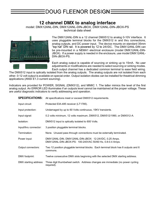
12 channel DMX to analog interfacemodel: DMX12ANL-DIN, DMX12ANL-DIN-JBOX, DMX12ANL-DIN-JBOX-PS technical data sheetThe DMX12ANL-DIN is a 12 channel DMX512 to analog 0-10V interface. Ituses pluggable terminal blocks for the DMX512 in and thru connections,analog outputs, and DC power input. The device mounts on standard 35mm“top hat” DIN rail. It is powered by 12 to 24VDC. The DMX12ANL-DIN canbe pre-mounted in a NEMA1 electrical enclosure (model DMX12ANL-DIN-JBOX). If a power supply is needed in the enclosure, use model DMX12ANL-DIN-JBOX-PS.Each analog output is capable of sourcing or sinking up to 15mA. No useradjustments or modifications are needed to select sourcing or sinking modes.Each output channel has a dedicated common terminal to ease field wiring.The DMX512 input is optically isolated from the analog outputs. The analog outputs are not isolated from each other. 0-12 volt output is available on special order. Output isolation diodes can be installed for theatrical dimming applications (ANSI E1.3 current sourcing).Indicators are provided for POWER, SIGNAL (DMX512), and MIMIC 1. The latter mimics the level of the first analog output. An ERROR LED illuminates if an outputs level cannot be maintained at the proper voltage. These are useful diagnostic indicators to verify addressing and operation.SPECIFICATIONS: All specifications meet or exceed DMX512 requirements.Input circuit: Protected EIA-485 receiver (LT1785).Input protection: Undamaged by up to 60 Volts continuous, 15KV transients.Input signal:0.2 volts minimum, 12 volts maximum, DMX512, DMX512/1990, or DMX512-A.Isolation: DMX512 input is optically isolated to 600 Volts.Input/thru connector:3 position pluggable terminal blocks.Termination:None. Unused pass through connections must be externally terminated.Power input:DMX12ANL-DIN, DMX12ANL-DIN-JBOX: 12-24VDC, 0.25 Amps.DMX12ANL-DIN-JBOX-PS: 100-240VAC 50/60 Hz, 0.8-0.4 Amps.Output connectors:Two 12 position pluggable terminal blocks. Each terminal block has 6 outputs and 6 commons.DMX footprint:Twelve consecutive DMX slots beginning with the selected DMX starting address.DMX starting address: Three digit thumbwheel switch. Address changes are immediate (no power cycling required).SPECIFICATIONS: (Continued)Local control: Address switch setting of 601 turns on output 1, 602 turns on output 2, etc.Switch setting of 697 turns on all outputs if any DMX level is above zero.Switch setting of 698 turns on all outputs if DMX is present.Switch setting of 699 turns on all outputs.Indicators: Red POWER indicator.Green MIMIC 1 indicator mimics the intensity of output 1 (useful in troubleshooting).Green SIGNAL indicator illuminates when DMX512 is present; flashes when local controlis active (address switch settings of 601 thru 624 and 697 thru 699).Yellow ERROR indicator illuminates if any output channel voltage differs from the targetvoltage for that channel.Cooling: Convection cooling, no fan required.Color: DMX12ANL-DIN: Black DIN mounting tray. Green PCB.DMX12ANL-DIN-JBOX: Grey NEMA1 electrical enclosure with knockouts on 2 surfaces.DMX12ANL-DIN-JBOX-PS: Grey NEMA1 electrical enclosure with knockouts on 2surfaces.Size and weight: DMX12ANL-DIN: 8.1" high x 5.0” wide x 2.2" deep, 1 pound.DMX12ANL-DIN-JBOX: 12” high x 12” wide x 4” deep, 10 pounds.DMX12ANL-DIN-JBOX-PS: 12” high x 12” wide x 4” deep, 11 pounds.LIMITED MANUFACTURER’S WARRANTYProducts manufactured by Doug Fleenor Design (DFD) carry a five-year parts and labor warranty against manufacturing defects. It is the customer's responsibility to return the product to DFD at the customer's expense. If covered under warranty, DFD will repair the unit and pay for return ground shipping. If a trip is necessary to the customer's site to solve a problem, the expenses of the trip must be paid by the customer.This warranty covers manufacturing defects. It does not cover damage due to abuse, misuse, negligence, accident, alteration, or repair by other than by Doug Fleenor Design.Most non-warranty repairs are made for a fixed $50.00 fee, plus shipping.Doug Fleenor Design, Inc.396 Corbett Canyon RoadArroyo Grande, CA 93420(805) 481-9599 voice and FAX(888) 4-DMX512 toll free (888) 436-9512web site: e-mail:************。
简单程序及工具说明
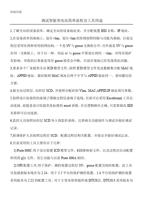
调试智能变电站简单流程及工具用途1,了解全站的设备清单,确定全站的设备地址表,并分配装置IED名称,IP地址。
2,在设备清单的基础上,划分vlan,划分vlan的原则按照间隔与功能为基础,目前过程层采用有两种常用组网结构,一个是SV与goose交换机分开,另外就是SV与goose 在同一交换机上,对于后一种,切忌sv与goose不要划分到同一vlan,对母差保护3,MAC地址,4,5,工具自IED6,7,8,1) Prate 800C:用于读出装置ICD模型文件,61850映射文件,以及过程层自动配置所用到g2c文件,其它功能与以前Prate 800A相同。
2) NPI配置工具:用于保护,测控装置过程层SV,goose配置及校时配置,此工具目前最新版本现在为2.24,用于1.5平台的保护测控装置,1.4平台的保护测控装置采用版本为2.22的配置工具。
对于主变本体智能终端DTU812,DTU813采用版本为2.20的配置工具,需根据工程实际手动选择sv,goose接受及发送光口。
3) scdtool,icdtool工具:scdtool主要用于制作站控层scd,过程层scd,并配置相关参数,icdtool用于编辑与修改icd模型文件,通常修改模型文件不要求,直接要求各个厂家提供正确的模型文件,可以通过icdtool工具验证icd模型文件。
4) NDIMan):用于智能终端goose,合并单元sv与goose及校时配置,需根据工程5)6)8)1.SMVSMVSMVnpi_debug/smv/countSMV接收丢帧次数npi_debug/smv/lost_timesSMV接收丢帧个数npi_debug/smv/lost_countSMV接收错误个数npi_debug/smv/format_errorSMV接收时标离散度smv_rxstat/max_intervalsmv_rxstat/min_interval注:该值÷16,转换为us单位的数值SMV链路状态Smv_status_infoconn_status,链路状态,1通0断SMV重采样找点统计wdStat/no_left_count,找左点失败次数wdStat/no_right_count,找右点失败次数wdStat/no_all_count,左右点均失败次数wdStat/interval_exception_count,左右点失败超差次数(反应合并单元发送不均匀)双AD检查异常统计dualAD_stat[smv][chnl]2.3.4.向NPU发送采样值统计向NPU发送丢帧次数Concat_Send_Err向NPU发送当前帧序号smv_pro_serial向NPU发送采样值Val_sample_int5.接收NPU报文统计dbg_pcap_stat.npu6.Goose接收统计7.Goose从xml10) systools工具:用于智能变电站采用的装置是103规约,需要做规约转换,以及61850映射。
智能连接器系统说明书

Complete Wireless Thermocouple Connector System The Smart Connector™U U ser Configurable for Type J, K, T, E, R, S, B, N, C Thermocouple InputU F ree Downloadable Software Converts Your PC Into a Multi-Channel Chart Recorder or Data LoggerU F CC Compliant (All Models)U B uilt-In Cold Junction Compensation and LinearizationU U nique Design Accepts Both Miniature and Standard Size Probes and ConnectorsU O ne Receiver Works with Multiple Wireless Remote ConnectorsU L ow Power Operation and Sleep Mode for Long Battery LifeU W ireless Connector Transmits Thermocouple Temperature, Ambient Temperature, Signal Strength and Battery Status in Real-TimeU I nterfaces with Model UWTC-REC1 for Multi-Channel PC Chart Recording and Data Logging or Model UWTC-REC2 (Single Channel Industrial Transceiver with Analog Output and Alarm)Thermocouple input. Wireless connector.Bumper Band TMP l u g Y o u r P r o b e I n t o a S m a r t C o n n e c t o r t o M a k e a S m a r t S e n s o r !A d d i t i o n a l R e c e i v e r s A v a i l a bl e F C C /I n d u s t r y C a n a d a , S R R C A p p r o v e d Omega’s wireless thermocouple connector features stand-alone, compact, battery powered thermocouple connectors that transmit their readings back to a host receiver up to 120 m (400') away. Each unit can be programmed in the field to work as a Type J, K, T, E, R, S, B, N or C calibration connector. When activated the connector will transmit readings continuously at pre-set time interval that was programmed by the user during the initial setup. Each unit measures and transmits: Thermocouple Input Reading, Connector Ambient Temperature, RF Signal Strength and Battery Condition to the host and is displayed on the PC screen in real-time using the downloadable software. When used with host receiver UWTC-REC1 data from up to 48 wireless thermocouple connectors can be received and displayed. Each unit includes free downloadable software that converts your PC into a strip chart recorder or data logger so readings can be saved and later printed or exported to a spread sheet file.When used with host transceiver UWTC-REC2 wireless data from one connector can be re-transmitted out ofthe receiver by a wired connection as an analog voltage, current or thermocouple signal to interface with acontroller, PLC or data acquisition board.UWTC-REC receivers work with up to 48 UWTC transmitters, and displays/logs the data to your PC or network. Sold separately.U p T o 48 C h a n n e l s!D o w n l o a d T C C e n t r a l S o f t w ar eSPECIFICATIONS (Complete specifications available online)UWTC Input: J, K, T, E, R, S, B, C or N; software selectable UWRTD Input: 100 Ω Pt RTD; 0.00385 or 0.00392 curve; software selectable Measurement Range: J: -100 to 760°C (-148 to 1400°F) K: -100 to 1260°C (-148 to 2300°F) T: -200 to 400°C (-328 to 752°F) E: -200 to 1000°C (-328 to 1832°F) R: 260 to 1760°C (500 to 3200°F) S: 260 to 1760°C (500 to 3200°F) B: 870 to 1820°C (1598 to 3308°F) C: 0 to 2315°C (32 to 4200°F) N: -100 to 1260°C (-148 to 2300°F) Pt100, 0.00385: -200 to 850°C (-328 to 1562°F) Pt100, 0.00392: -100 to 457°C (-148 to 854°F)Accuracy: Types J and K: ±0.5% rdg or ±1.0°C (1.8°F), whichever is greater Types T, E, and N: ±0.5% rdg or ±2.0°C (3.6°F), whichever is greater Types R, S, B and C: ±0.5% FS Pt100: ±0.5°C (1.0°F)Resolution: 1°C/1°FCold Junction Compensation (Automatic): -10 to 70°C (14 to 158°F)Thermocouple Connection: Universal female accepts both standard male (OSTW Series) or miniature male (SMPW Series) mating connectorRTD: Series “T” receptacle, type TA4M; TA4F mating connector includedOperating Environment: -10 to 70°C (14 to 158°F)Computer Interface: USB (one interface cable included with receiver)Type K shown Miniature connector (SMP)Thermocouple input.Note: USB programming cable included with compatible UW Series wireless receivers and transceivers.UWTC comes complete with 3.6V “AA” lithium battery, mounting bracket, Type K beaded wire thermocouple and operator’s manual. UWRTD comes complete with 3.6V “AA” lithium battery, mounting bracket, TA4F mating connector and operator’s manual.Ordering Example: UWTC-2, wireless thermocouple connector/transmitter with 120 m (400') range, plus UWTC-REC1 48-channel receiver/host.Standard connector (OST)Wireless connectors convert your thermocouple or RTD to a wireless signal.(one included)UWRTD-2Thermocouple Included!Transmit Sample Rate: Programmable from 1 sample/minute to 1 sample/every 5 seconds Radio Frequency (RF) Transceiver Carrier: ISM 2.4 GHz, direct sequence spread spectrum, license free worldwide (2.450 to 2.490 GHz -12 channels)RF Output Power U WTC-2, UWRTD-2: 10dBm (10 mW)Range of RF Link U WTC-2, UWRTD-2: Up to 120 m (400') outdoor line of sight; Up to 45 m (130') indoor/urban RF Data Packet Standard: IEEE 802.15.4, open communication architecture Downloadable Software: Compatible with Windows (2000, XP, Vista, and 7) operating system Connector Internal Battery: One 3.6 V lithium, 2.4 Ah capacity (AA) (included)Battery Life (Typical- 1 sample/minute reading rate @ 25°C (77°F): 1 year Data Transmitted to Host: Thermocouple Reading, Connector Ambient Reading, RF Transmit Strength and Battery Condition Dimensions: 100 L x 50 W x 25 mm H (without antenna) (4 x 2 x 1")Weight: 70 grams Case: ABS plastic UWTC-2RTD input Note: Because of transmission frequency regulations, the UWTC-2 and UWRTD-2 products are approved for use in the United States, Canada, Europe, Mexico, Brazil, China, Korea, Singapore, and Japan.。
DBI-SALA Uni 8 水平保护线缆系统指南规范说明书

SECTION 112429.17 - HORIZONTAL FALL PROTECTION - CABLEPART 1 - GENERAL1.1SECTION INCLUDESA.Provide horizontal cable fall protection system, including end anchors, energy absorbers,intermediate cable supports, variable cable supports, traveler and corner cable supports asrequired.1.2REFERENCE STANDARDSA.ANSI A10.32, "Personal Fall Protection Used in Construction and Demolition Operations."B.ANSI Z359.1, "Safety Requirements for Personal Fall Arrest Systems, Subsystems andComponents."C.ASTM A123 / A123M, "Standard Specification for Zinc (Hot-Dip Galvanized) Coatings onIron and Steel Products."D.ASTM A747/A747M, "Standard Specification for Steel Castings, Stainless, PrecipitationHardening."E.ASTM A36, "Standard Specification for Carbon Structural Steel."F.ASTM A666, "Standard Specification for Annealed or Cold-Worked Austenitic Stainless SteelSheet, Strip, Plate, and Flat Bar."G.ASTM A500, "Standard Specification for Cold-Formed Welded and Seamless Carbon SteelStructural Tubing in Rounds and Shapes."H.AWS D1.1/D1.1M, "Structural Welding Code - Steel."1.Welding rods and bare electrodes: Select according to AWS specifications for metalalloy welded.I.CSA Z259.16, "Design of Active Fall Protection Systems."J.OSHA 1926.502, "Fall Prevention Systems and Criteria and Practices."1.3ADMINISTRATIVE REQUIREMENTSA.Coordination: Coordinate the installation of horizontal cable fall protection system withstructural supports and finish materials.1.4SUBMITTALSA.Product Data: Manufacturer's data and product information indicating the sizes, descriptions,capacities, test certifications, and other descriptive data showing in sufficient detail that theproduct complies with the contract requirements.B.Shop Drawings: For fabrication showing the complete fall protection system. Layout drawingsof each system in relation to the supporting structure indicating the locations of properly labeled components.C.Furnish proof of installer’s certification approval by manufacturer in the form of the installer'scurrent certificate issued by the manufacture.D.Product Certificate: Containing the manufacturer's batch number on each individual componentused in the systems.E.Designer’s Qualifications Statement.F.Systems Manual:1.Maintenance Procedures: Including parts list and maintenance requirements for allequipment.2.Operation Procedures: Indicating proper use of equipment for safe operation of thesystems.3.Manufacturer's catalog data indicating the sizes, descriptions, capacities, testcertifications, and other descriptive data showing sufficient detail that the productcomplies with the contract requirements.G.Record Documents: Include a copy of Record Drawings in the systems manual.H.Warranty: Submit manufacturer warranty and ensure that forms have been completed inOwner's name and registered with manufacturer.I.Delegated-Design Submittal: For fall protection system, including analysis data signed andsealed by the qualified professional engineer responsible for their preparation.1.5QUALITY ASSURANCEA.Perform design under direct supervision of a Professional Engineer experienced in design ofthis type of work and licensed in the [State][Commonwealth][Province] of <insert name ofstate, commonwealth, or province>.B.Install fall protection system by manufacturer's authorized, trained, and certified personnel.1.6DELIVERY, STORAGE, AND HANDLINGA.Deliver materials in manufacturer's original unopened packaging.B.Store materials in original protective packaging.C.Prevent soiling, physical damage, or moisture.1.7PROJECT CONDITIONSA.Coordinate layout and installation of framing and reinforcements for fall protection systemanchors.1.8WARRANTYA.Correct defective Work within a one year period after Date of Substantial Completion.B.Provide lifetime manufacturer warranty.PART 2 - PRODUCTS2.1MANUFACTURERSA.Basis of Design Product: Subject to compliance with requirements, provide Capital Safety;DBI-SALA® Uni 8™ Horizontal Lifeline Cable System.B.Substitutions: Not PermittedC.Source Limitation: Obtain fall protection system and components from a single manufacturer.2.2SYSTEM DESCRIPTIONA.Allow users to walk uninterrupted the entire length of the system and provide secure anchorageto arrest a fall. System to allow attachment at any point along the cable and enables freedom ofmovement along the cable as it passes by intermediate anchors.B.Maximum span of 39 feet(12 m) between anchors and provides continuous hands free accessfor the user of the roof fall protection system.C.System must not be used as a tieback anchor for façade maintenance.2.3PREFORMANCE REQUIREMENTSA.Delegated Design: Engage a qualified professional engineer, as defined in Section 014000"Quality Requirements," to design fall protection system.B.Structural Performance: Fall protection systems shall withstand the effects of loads and stresseswithin limits and under conditions required by [CSA Z259.16,][ANSI A10.32,][ANSIZ359.1,][and][OSHA 1926.502].1.Allow for multiple users, based on required system calculations.2.System designed for <insert maximum number of individuals> simultaneous usersmaximum.3.System capable of spanning 39 feet(12 m) between intermediate supports.4.Maximum allowable force on anchors: 4271 lbs.(19 kN).2.4COMPONENTSA.Cable: 7x7, 5/16 inch(8 mm) 316 Stainless Steel Wire, Breaking Strength 8543 lbs.(38 kN).B.End Anchorage Connector: 316 Stainless Steel, electropolished.1.Greater than 10,116 lbs.(45 kN) minimum breaking strength.C.Tensioner: Uni 8™ System Tensioner - 316 stainless steel with anti-seizure tensioning unit andtension indicator disc.D.Intermediate Bracket: Uni 8™ intermediate bracket - 316 stainless steel, electropolished.Variable positioning available to suit a range of applications. Re-orientates load in the event ofa fall.E.90 and 45 Degree Corners: Uni 8™ - 90 and 45 degree corners. 316 stainless steel,electropolished. Other angles achieved using variable bracket.F.Variable Guide: 316 Stainless Steel, electropolished.G.Swage Toggles: Uni 8™ Swage Toggles -316 Stainless Steel.H.UniGrab Attachment Device with Carabiner: ASTM A747/A747M, electropolished andnumbered.I.Energy Absorber: Inline Force Management Energy Absorber - 316 Stainless Steel,electropolished.J.Fabricated supports: Stainless steel or hot-dip galvanized, carbon steel ASTM A123 / A123M.1.Steel Plates, Shapes, and Bars: ASTM A36.2.Steel Tubing: ASTM A500, cold formed.3.Welding rods and bare electrodes: Select according to AWS specifications for metalalloy welded.2.5MATERIALSA.Primary cable assembly components: Stainless steel: ASTM A666, Type 316.B.Connectors: Comply with OSHA regulation 1926.502.2.6FABRICATIONA.Fabricate anchoring devices as recommended by the manufacturer to provide adequate supportfor intended use. Shop fabricate required anchorage posts using structural steel with materialtest certificates for full material traceability.B.Welding: AWS structural specification D1.1 by certified welders.C.Fabricate joints in a manner to discourage water accumulation.D.Swaging: Swage cable in-line with the anchor point.E.Finishes:1.Stainless Steel: Electropolished for corrosion resistance.2.Structural Steel: Zinc Galvanized for corrosion resistance.2.7ACCESSORIESA.Fasteners: Designed to support a load on the system of 2 times the maximum design loadwithout failure.B.Signage: Provide signs and system identification tags.C.Flashing: Comply with requirements of Section [076200 "Sheet Metal Flashing and Trim."][077100 "Roof Specialties."][077200 "Roof Accessories."] <insert roofing section number and roofing section title>D.Sealant: Comply with requirements of Section 079200 "Joint Sealants."PART 3 - EXECUTION3.1EXAMINATIONA.Examine areas and conditions, with Installer present, for compliance with requirements forinstallation tolerances and other conditions affecting performance of fall protection equipment.B.Proceed with installation only after unsatisfactory conditions have been corrected.3.2PREPARATIONA.Coordinate location of fall protection equipment indicated to be attached to structural substrateor surface of roofing system, and furnish anchoring devices with templates and diagrams.3.3INSTALLATIONA.Install according to approved shop drawings and manufacturer's instructions.B.Install anchorage and fasteners in accordance with manufacturer's recommendations to obtainthe allowable working loads published in the product literature and in accordance with thisspecification.C.Exposed work shall be true to line and level with accurate angles, surfaces and with straightsquare edges. Coordinate anchorage system with supporting structure.D.Do not load or stress system until materials and fasteners are properly installed and ready forservice.E.Do not use until trained in the use of the system.3.4FIELD QUALITY CONTROLA.Provide manufacturer's certified installer to inspect installed fall protection system.B.Test fall protection system for compliance with the following requirements:1.Ensure that system components operate as specified.3.5ADJUSTINGA.Adjust fall protection components to function smoothly and safely.3.6CLEANINGA.Clean components of any deleterious coatings or compounds.B.Remove loose materials, crating, and packing materials from site.3.7CLOSEOUT ACTIVITIESA.Demonstration: Demonstrate operation of system to Owner's personnel.1.Briefly describe function, operation, and maintenance of each component.B.Training: Train Owner's personnel on operation and maintenance of system.e operation and maintenance manual as training reference, supplemented withadditional training materials as required.2.Provide minimum of two hours of training.3.Provide training at the lifeline installation site.4.Training to take place at the completion of the installation.END OF SECTION。
wbh-812技术说明书V1.40用
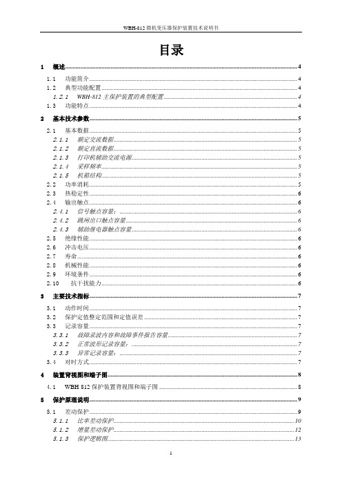
目录1概述 (4)1.1功能简介 (4)1.2典型功能配置 (4)1.2.1WBH-812主保护装置的典型配置 (4)1.3功能特点 (4)2基本技术参数 (5)2.1基本数据 (5)2.1.1额定交流数据 (5)2.1.2额定直流数据 (5)2.1.3打印机辅助交流电源 (5)2.1.4采样频率 (5)2.1.5机箱结构 (5)2.2功率消耗 (5)2.3热稳定性 (6)2.4输出触点 (6)2.4.1信号触点容量: (6)2.4.2跳闸出口触点容量 (6)2.4.3辅助继电器触点容量 (6)2.5绝缘性能 (6)2.6冲击电压 (6)2.7寿命 (6)2.8机械性能 (6)2.9环境条件 (6)2.10抗干扰能力 (6)3主要技术指标 (7)3.1动作时间 (7)3.2保护定值整定范围和定值误差 (7)3.3记录容量 (7)3.3.1故障录波内容和故障事件报告容量 (7)3.3.2正常波形记录容量: (7)3.3.3异常记录容量: (7)3.4对时方式 (7)4装置背视图和端子图 (8)4.1WBH-812保护装置背视图和端子图 (8)5保护原理说明 (9)5.1差动保护 (9)5.1.1比率差动保护 (10)5.1.2增量差动保护 (12)5.1.3保护逻辑图 (13)5.1.5差流越限保护 (14)5.2过流保护 (14)5.2.1判据说明 (14)5.2.2过流保护的逻辑图 (14)6整定内容及整定说明 (15)6.1通讯参数设置 (15)6.2WBH-812/2的保护整定清单 (15)6.2.1WBH-812/2的保护软压板清单 (15)6.2.2WBH-812/2的保护定值清单 (16)6.2.3WBH-812/2的保护出口清单 (17)7保护装置整定计算 (18)7.1差动保护整定计算 (18)7.1.1差动保护各侧电流相位差的补偿 (18)7.1.2平衡系数的计算 (18)7.1.3最小动作电流的整定 (19)7.1.4最小制动电流的整定 (20)7.1.5比率制动系数S的整定 (20)7.1.6灵敏度的计算 (21)7.1.7谐波制动系数的整定 (21)7.1.8差流速断的整定 (21)7.1.9差流越限的整定 (22)7.1.10差动保护参数整定的举例说明 (22)7.2过流保护整定计算 (24)8保护装置保护性能测试 (25)8.1变压器差动保护 (25)8.1.1最小动作电流 (26)8.1.2比率制动系数(即制动特性斜率) (26)8.1.3励磁涌流闭锁 (28)8.1.4TA断线闭锁差动 (28)8.1.5差流速断动作电流 (28)8.1.6动作时间测试 (29)8.1.7差流越限电流 (29)8.1.8差流越限延时 (29)8.1.9TA断线 (29)8.2过流保护 (31)8.2.1动作电流 (31)8.2.2延时时间 (31)9订货须知 (31)10附录一:保护性能测试准备工作 (31)11附录二:装置使用说明 (32)12附录三:装置运行说明 (32)12.1面板指示灯说明 (32)12.2运行工况及说明 (32)12.3故障报文和处理措施 (33)13附录三:装置通讯说明(IEC 60870-5-103规约) (33)13.1保护软压板遥信 (33)13.2保护软压板控制 (33)13.3状态信息 (34)13.4故障信息 (34)13.5告警信息 (34)13.6自检信息 (34)1概述1.1功能简介WBH-812微机变压器保护装置适用于110 kV及其以下各种电压等级各种接线方式的变压器。
DBU-813智能接口调试大纲

许继智能变电站智能接口DBU-813调试大纲许继电气股份有限公司1 装置外观检查表1 装置外观检查记录单2 插件外观检查表2 插件外观检查记录单3 绝缘介质强度检查试验工具:兆欧表(Model 3005A),耐压试验机(CJ2672或DT903),万用表,导线若干。
3.1 绝缘电阻检查3.1.1 试验要求a.额定绝缘电压高于63V时,用开路电压为500V的兆欧表测定其对地绝电阻值应不小于100 MΩ;(适用于本装置开出回路、开入回路和电源回路)b.额定绝缘电压小于或等于63V时,用开路电压为250V的兆欧表测定其对地绝电阻值应不小于100 MΩ。
(适用于本装置通讯及弱电回路)3.1.2 试验方法首先应确保箱体可靠接地,再将兆欧表水平放置,其接地端接大地,测试端接所要检验的端子,顺时针摇动手柄至指针不发生变化时读取读数,应不低于试验要求的电阻值,兆欧表无告警声。
在测量某一组回路对地绝缘电阻时,应将其他各组回路都接地。
表3-1 绝缘电阻记录单3.2 介质强度检查3.2.1 试验要求a.额定绝缘电压高于63 V的导电电路分别对地(即外壳或外露的非带电金属零件)以及回路之间,能承受50Hz、2000V(有效值)的交流电压,历时1min 的检验无击穿或闪络现象。
出厂试验时,允许试验历时缩短为1 s,但此时试验电压应提高10%。
(适用于本装置开出回路、开入回路)b.针对电源插件等容性回路为躲避漏电流,也可按直流2800V、漏电流10mA、历时1min进行绝缘介质强度试验。
出厂试验时,允许试验历时缩短为1 s,但此时试验电压应提高10%。
(适用于本装置电源回路)3.2.2 试验方法试验设备的开路电压初调到低于50%的规定值,再加到被试装置,试验电压从这一初始值增加到规定值,其间按漏电流10mA,历时 1min,观察试验设备不应超漏指针回零,不应发出报警的蜂鸣音,观察机箱无闪络、击穿现象,不损坏电气性能,然后迅速平稳下降至零。
128ENM安装使用说明书
安装使用说明书
北京利达华信电子有限公司
BEIJING LEADER HUAXIN ELECTRONICS CO., LTD.
JB-QB-LD128EN(M)安装使用说明书
目录
第一章 概述.............................................................................................................................2 第二章 技术特性.....................................................................................................................2 第三章 结构特性.....................................................................................................................4 第四章 安装与调试.................................................................................................................7 第五章 系统设置.....................................................................................................................8 第六章 使用与操作...............................................................................................................20 第七章 联动控制盘...............................................................................................................28 第八章 故障分析与排除.......................................................................................................29 第九章 注意事项...................................................................................................................29 第十章 售后服务...................................................................................................................29
Luxul XMS-1208P 12 Port 8 PoE+ 前端面板机柜交换机说明书

PoE Power Budget 130 watts maximum
Max Power Consumption 170W
VLAN 802.1Q max 4094 VIDs Supports 1 management VLAN
Warranty:
Three-year limited warranty
Minimum System Requirements
Ethernet cable Computer with Windows, Mac, or Linux OS
Package Contents
XMS-1208P Switch Power cord Rack mount kit Quick Install Guide
Quality of Servi来自e 4 queues per port (QoS) Queue handling: Strict, Weighted Round Robin (WRR) CoS based on DCSP, 802.1P, and port-based priority queues Port- based bandwidth control
Network Data Transfer Rate Ethernet: 10Mbps (half-duplex) Ethernet: 20Mbps (full-duplex) Fast Ethernet: 100Mbps (half-duplex) Fast Ethernet: 200Mbps (full-duplex) Gigabit Ethernet: 2000Mbps (full-duplex)
- 1、下载文档前请自行甄别文档内容的完整性,平台不提供额外的编辑、内容补充、找答案等附加服务。
- 2、"仅部分预览"的文档,不可在线预览部分如存在完整性等问题,可反馈申请退款(可完整预览的文档不适用该条件!)。
- 3、如文档侵犯您的权益,请联系客服反馈,我们会尽快为您处理(人工客服工作时间:9:00-18:30)。
DBU-812智能接口单元技术使用说明书2008.091目 录1概述..................................................................................................................................1-1 1.1应用范围...............................................................................................................1-11.2产品特点...............................................................................................................1-1 2技术参数..........................................................................................................................2-1 2.1基本数据...............................................................................................................2-1 2.2环境条件...............................................................................................................2-1 2.3绝缘性能...............................................................................................................2-1 2.4抗电磁干扰能力...................................................................................................2-2 2.5机械性能...............................................................................................................2-2 2.6寿命.......................................................................................................................2-2 3产品功能介绍..................................................................................................................3-1 3.1开入功能...............................................................................................................3-1 3.2开出功能...............................................................................................................3-1 3.3机构操作回路.......................................................................................................3-1 3.4逻辑闭锁功能.......................................................................................................3-2 3.5对时功能...............................................................................................................3-2 3.6通讯功能...............................................................................................................3-2 3.7记录功能...............................................................................................................3-3 3.8装置自检功能.......................................................................................................3-3 4装置硬件结构及典型接线..............................................................................................4-1 4.1结构与安装...........................................................................................................4-1 4.2装置正背视示意图...............................................................................................4-2 4.3插件功能说明.......................................................................................................4-3 4.4装置端子图...........................................................................................................4-4 5附录一 过程层配置表. (1)5.1GOOSE接收配置 (1)5.2GOOSE发送配置 (2)6附录二 装置版本和事件信息查询方法 (2)6.1调试计算机和装置的连接说明 (2)6.2CPU版本信息 (3)6.3详细事件查询 (3)21概述1.1应用范围智能接口单元作为数字化变电站三层结构中过程层的典型设备,主要担负一个间隔内一次设备位置和状态告警信息的采集和监视,对设备的智能控制,并具有防误操作功能。
按照不同类型的一次设备,智能接口单元分为断路器智能接口单元和变压器智能接口单元。
DBU-812断路器智能接口单元(以下简称DBU-812或装置)适用于一个完整的110kV 单跳闸线圈的断路器间隔——最大容量双母线带旁母接线形式:1个断路器和6个刀闸。
DBU-812的应用,光缆彻底取代了电缆,各类信息全部通过光缆交互,将传统断路器改造为满足数字化需求的智能一次设备。
1.2产品特点强抗干扰能力软硬件设计上充分考虑过程层相对恶劣的运行环境,采取6U全封闭机箱,整体面板,强弱电严格分开,装置的抗干扰能力、抗震动能力大大提高,对外的电磁辐射也满足相关标准。
强大的自检功能除提供完善的硬件自检功能(包括开出回路、定值、程序、电源等14类自检项目)外,充分考虑全数字化改造后,开关量、控制量采用光纤网络传输带来的误动和拒动问题,提供详尽GOOSE自检机制。
可视化的逻辑开发采用可视化的逻辑开发工具V L D,在V L D的开发环境下所有的保护逻辑都是由不同可视化的柔性继电器组成,实现微机保护的完全透明化设计。
保护源代码完全由软件机器人自动生成,正确率达到100%,杜绝了人为原因产生软件B ug。
完善的功能配置提供强大的控制和监视功能,完成一个断路器间隔内所有位置和状态信息的采集和监视、断路器与刀闸的远方/就地分合控制、防误操作等功能,真正实现智能化一次设备。
快速灵敏的响应速度采用智能循检技术,设备从接收到跳闸GOOSE到开出继电器动作,延时≤4ms,大大提高了设备反应速度,克服了数字化改造后,保护动作到切除故障时间有所增大的问题。
全面支持I EC 61850规约做为新型过程层设备,适用于符合I EC 61850规范的全数字化变电站,实现各配套厂家的无缝联接,真正实现间隔层和过程层智能设备间的数据共享。
完善的事件记录功能可循环记录200次事件顺序记录和异常告警信息。
1-12技术参数2.1基本数据a)额定数据额定直流电压:220V或110V(正常工作范围80%~115%);跳闸保持电流:0.25A~4A(订货注明);合闸保持电流:0.25A~4A(订货注明)。
b)触点性能装置的出口触点,在电压不大于250V,电流不大于0.5A,时间常数为5ms±0.75ms 的直流有感负荷电路中,断开容量为50W,长期允许通过电流为5A。
c)开关状态量空触点方式接入,配置30路。
输入电压:DC220V/110V。
分辨率:≤1msd)开关量输出配置32路开出接点。
断路器分闸动作延时:≤4ms(包括继电器固有时间)断路器合闸和刀闸动作延时:≤10ms(包括继电器固有时间)e)功率消耗直流回路功率消耗:不大于60W。
f)操作回路满足一台单跳闸线圈三相断路器。
2.2环境条件a)环境温度:-25℃~+55℃(根据合同要求)。
b)相对湿度:5%~95%.c)大气压力:80kP a~110 kP a2.3绝缘性能a)绝缘电阻装置所有电路与外壳之间的绝缘电阻在标准试验条件下,不小于100 MΩ。
b)介质强度装置的导电部分对外壳或外露的非导电金属之间,以及电气上无联系的各带电的导电电路之间,能耐受交流50 Hz,电压2 kV(有效值),历时1 min试验,而无绝缘击穿或闪络现象。
