TRF7003PK中文资料
PF700技术手册
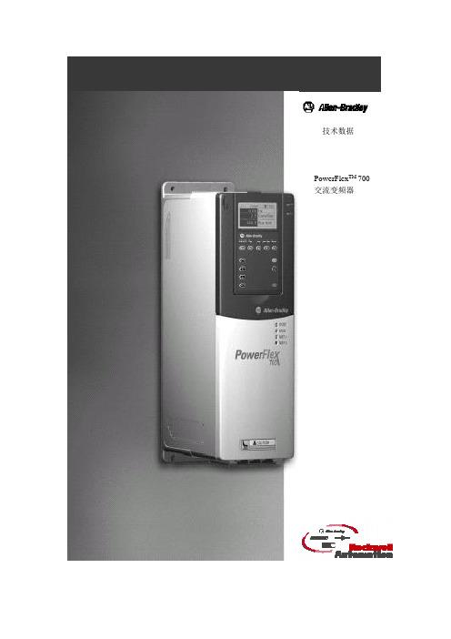
技术数据PowerFlex TM 700交流变频器PowerFlex TM 700交流变频器技术数据正象人们对罗克韦尔自动化产品所期望的那样,PowerFlex 700交流变频器提供了简捷实用的卓越性能。
具有世界级性能的包装结构不仅精巧而且极具竞争价格。
PowerFlex 700交流变频器主要用于控制三相感应电动机,从最简单的速度控制到最苛刻的转矩控制,满足应用系统的要求。
它有两种配置方式:其中标准控制主要是电压/频率(V/f)控制和无速度传感器矢量控制;获得艾伦-布拉德利专利的Force TM技术主要是电压/频率控制、无速度传感器矢量控制和磁场定向控制。
目录说明页码标准的变频器编辑 (3)目录号说明 (5)PowerFlex700变频器…………………………… .6可选件选型 (7)附件 (11)PowerFlex 700可配置的变频器 (14)电源接线 (15)电源端子 (16)控制端子 (19)推荐使用电缆 (23)功率额定值、分支电路保护及功率损耗 (24)最大导线长度 (29)近似尺寸 (31)控制与性能 (36)参数列表 (38)2标准的变频器编辑灵活的包装和安装•IP20,1型——可用于传统方式的控制柜柜内或柜外的安装。
为使安装和可拆卸的进线电缆引入板更易于安装和更换而不影响其它的接线。
•Zero Stacking TM——在环境温度高达500C的情况下,仍允许变频器之间采用零间隙并排式安装。
这种独特的书架式设计允许在访问一个变频器的同时不影响其它的变频器。
节省空间的硬件特性•集成的EMC滤波器附带内置的共模磁心及共模电容器,它提供了一个紧凑的、集于一体的完整解决方案,用以满足EMC要求,包括欧洲的CE标准。
•内部通讯允许用户将变频器集成到制造过程中。
所有内部通讯选项的状态指示器在面板上都是可见的,易于设置和监视变频器的通讯。
当用户进行控制、组态和采集数据的时候,可以很容易地管理从车间底层到企业顶层的信息并无缝地将它们集成为一个完整的系统。
龙芯7a2000独显桥片数据手册说明书
龙芯7A2000独显桥片数据手册V1.12022年10月龙芯中科技术股份有限公司版权声明本文档版权归龙芯中科技术股份有限公司所有,并保留一切权利。
未经书面许可,任何公司和个人不得将此文档中的任何部分公开、转载或以其他方式散发给第三方。
否则,必将追究其法律责任。
免责声明本文档仅提供阶段性信息,所含内容可根据产品的实际情况随时更新,恕不另行通知。
如因文档使用不当造成的直接或间接损失,本公司不承担任何责任。
龙芯中科技术股份有限公司Loongson Technology Corporation Limited地址:北京市海淀区中关村环保科技示范园龙芯产业园2号楼Building No.2, Loongson Industrial Park, Zhongguancun Environmental Protection Park电话(Tel):************传真(Fax):************阅读指南《龙芯7A2000独显桥片数据手册》主要介绍龙芯7A2000独显桥片接口结构,特性,电气规范,以及硬件设计指导。
版本信息手册信息反馈: *******************目录版本信息 (5)图目录.............................................................................................................................................. I II 表目录. (IV)附录目录 (V)1.简介 (1)1.1技术指标 (1)1.2典型应用 (2)1.2.1单路应用 (2)1.2.2双路应用 (3)1.3订购信息 (4)1.4术语 (4)1.5文档约定 (4)1.5.1引脚信号命名 (4)1.5.2数值表示 (5)1.5.3寄存器域 (5)2.接口信号 (6)2.1信号类型定义 (6)2.2接口信号说明 (6)2.2.1HT接口 (6)2.2.2PCIE接口 (8)2.2.3显存接口 (9)2.2.4网络接口 (9)2.2.5SATA接口 (10)2.2.6VGA接口 (10)2.2.7HDMI接口 (11)2.2.8USB接口 (11)2.2.9HDA接口 (12)2.2.10SPI接口 (12)2.2.11LPC接口 (12)2.2.12I2C接口 (13)2.2.13UART接口 (13)2.2.14PWM接口 (13)2.2.15GPIO接口 (13)2.2.16RTC信号 (14)2.2.17电源管理接口 (14)2.2.18时钟信号 (15)2.2.19芯片配置接口 (15)2.2.20中断接口 (16)2.2.21JTAG接口 (17)2.2.22引脚复用表 (17)3.功能及接口说明 (20)3.1 HT接口 (20)3.2 PCIE接口 (20)3.3 GPU (20)3.4 显示接口 (20)3.5 显存接口 (21)3.6 USB接口 (21)3.7 SATA接口 (21)3.8 网络接口 (22)3.9 HDA接口 (22)3.10 I2S接口 (22)3.11 SPI接口 (22)3.12 LPC接口 (23)3.13 UART接口 (23)3.14CAN (23)3.15 I2C接口 (23)3.16 PWM (24)3.17HPET (24)3.18 RTC (24)3.19 ACPI接口 (24)3.20 GPIO接口 (25)3.21 JTAG接口 (25)4.时钟 (26)4.1时钟内部框图 (26)4.2芯片时钟介绍 (26)4.3时钟功能描述 (27)4.4频率配置 (28)5.电源管理ACPI (29)5.1电源域 (29)5.2功能描述 (29)6.热设计 (30)6.1热参数 (30)6.2焊接温度及焊接曲线 (30)7.电气特性 (32)7.1最大额定工作条件 (32)7.2工作电源 (33)7.3典型应用功耗 (34)7.4电源时序 (36)7.4.1使能ACPI_EN (36)7.4.2不使能ACPI_EN (43)8.封装信息 (46)8.1封装尺寸 (46)8.2信号位置分布 (48)8.3芯片引脚排布 (48)9.产品标识 (49)附录A:芯片引脚排布图 (50)图1-1 龙芯7A2000顶层结构图 (1)图1-2单路应用示意图 (3)图1-3双路应用示意图 (3)图4-1芯片时钟结构图 (26)图6-1焊接回流曲线 (31)图7-1冷启动上电时序(RTC掉电) (36)图7-2热复位时序图 (38)图7-3 S0到S3及S3到S0时序图 (40)图7-4 S0到S4/S5及S4/5到S0状态时序图 (41)图7-5 不使能ACPI功能时的冷启动上电时序(RTC掉电) (43)图7-6 不使能ACPI功能时的热复位时序图 (44)图8-1 封装尺寸 (46)图8-2 DIE位置 (47)图8-3信号引脚分布总览(顶视图) (48)图9-1 产品标识 (49)表1-1龙芯7A2000芯片分级 (4)表1-2术语和缩略语表 (4)表2-1信号类型说明 (6)表2-2 HT接口 (6)表2-3 PCIE接口 (8)表2-4 显存接口 (9)表2-5 网络接口 (9)表2-6 SATA接口 (10)表2-7 VGA接口 (10)表2-8 HDMI接口 (11)表2-9 USB接口 (11)表2-10 HDA接口 (12)表2-11 SPI接口 (12)表2-12 LPC接口 (12)表2-13 I2C接口 (13)表2-14 UART接口 (13)表2-15 PWM接口 (13)表2-16 GPIO接口 (13)表2-17 RTC接口 (14)表2-18 电源管理接口 (14)表2-19 时钟信号 (15)表2-20 芯片配置接口 (15)表2-21 中断接口 (16)表2-22 JTAG接口 (17)表2-23引脚复用表 (17)表4-1桥片时钟输入 (27)表4-2桥片时钟输出 (27)表6-1龙芯7A2000的热阻参数 (30)表6-2回流焊接温度分类表 (30)表7-1芯片绝对最大额定电压 (32)表7-2工作电源要求 (33)表7-3典型应用功耗 (34)表7-4上电时序要求(示例) (37)表7-5热复位时序约束 (38)表7-6 S0到S3/S4/S5及S3/S4/S5到S0状态时序约束 (42)表7-7 不使能ACPI功能时的上电时序要求 (44)表7-8 不使能ACPI功能时的热复位时序约束 (44)附录目录图A -1芯片引脚排布1/4(顶视图,从左至右) (51)图A -2芯片引脚排布2/4(顶视图,从左至右) (52)图A -3芯片引脚排布3/4(顶视图,从左至右) (53)图A -4芯片引脚排布4/4(顶视图,从左至右) (54)1.简介龙芯7A2000型处理器独显桥片(后文也简称为7A2000)是龙芯7A1000的升级产品。
调速器硬件手册

ETD 790直流调速器
页码:2 /86
ETD 790直流调速器 电流预测控制
6.4e 模拟输出 .............................................................................................................. 39 6.4f 422/485串行口....................................................................................................... 41 6.4g 直流测速电机反馈接线 ......................................................................................... 42 6.4h 用于指示输入和输出的LED指示器 ....................................................................... 43 6.5 RS 232、CAN总线、编码器1、编码器2的连接器....................................................
FX-730中文资料
Vectron International, 267 Lowell Road, Hudson, NH 03051
Page 3 of 8
Tel: 1-88-VECTRON-1 • Web: Rev: 24Jul07
元器件交易网
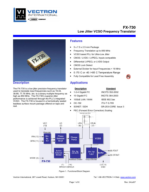
FX-730 Low Jitter VCSO Frequency Translator
Description
Applications
The FX-730 is a low jitter precision frequency translator used to translate input frequencies such as 19.44, 38.88, 77.76 MHz, etc. to a binary multiple frequency as high as 850 MHz. The FX-730’s superior jitter performance is achieved through the PLL’s integrated VCSO. The FX-730 is housed in a hermetically sealed leadless surface mount package offered on tape and reel.
1. It is recommended that a buffer driver is used for best noise isolation. 2. Do not leave the MODE pin floating, it should be set to logic 0 or ground for normal operation. 3. BRCLK and CBRCLK should be left floating if not used. 4. FIN, CFIN, BRCLK, and CBRCLK have internal pull-up/pull-down resistors and it is recommended to AC couple these inputs.
施耐德 APC SMV系列750, 1000, 1500, 2000, 3000 VA说明书
Important Safety InstructionsSAVE THESE INSTRUCTIONS - This manual contains importantinstructions that should be followed during installation and maintenance of the Easy UPS and batteries.Read these instructions carefully and look at the equipment to becomefamiliar with the device before trying to install, operate, service or maintain it. The following special messages may appear throughout this manual or on the equipment to warn of potential hazards or to call attention to information that clarifies or simplifies a procedure.The addition of either symbol to a “Danger” or “Warning” safetylabel indicates that an electrical hazard exists which will resultin personal injury if the instructions are not followed.This is the safety alert symbol. It is used to alert you to potentialpersonal injury hazards. Obey all safety messages that followthis symbol to avoid possible injury or death.Easy UPS SMV Series 750, 1000, 1500, 2000, 3000 VA2Product Handling GuidelinesSafety and General InformationGeneral safety• Adhere to all national and local electrical codes.• This UPS is for indoor use only. To prevent the risk of fire or electric shock, install in temperature and humidity controlled indoor area, free of conductive contaminants.Easy UPS must be installed indoor with controlled environment free of excessive dust, corrosive air or conductive dust. Keep out of direct sun light, water and heat sources.• Place the unit on the stable floor.• Be sure that the mains socket outlet that supplies the UPS is installed near the UPS and easily accessible. Avoid using extension cords.• UPS must be connected to an earthed mains socket outlet.• Connect the power cable directly to a wall outlet. Do not use surge protectors or extension cords.• CAUTION : This UPS is designed to satisfy the requirement of PCs only.• Do not connect printers, heaters, or copiers to the UPS.Battery safety<18 kg <40 lb 18-32 kg 40-70 lb 32-55 kg 70-120 lb >55 kg >120 lb• Servicing of user replaceable batteries should be performed orsupervised by personnel knowledgeable about batteries and requiredprecautions.NOTE: In this case batteries are not user replaceable.• When replacing battery the UPS must be off, and its AC inletunplugged.• CAUTION: Do not dispose of batteries in a fire. The batteries mayexplode.• CAUTION: Do not open or mutilate batteries. Released material isharmful to the skin and eyes and may be toxic.• CAUTION: A battery can present a risk of electrical shock and burns byhigh short-circuit current. Contact with any part of a grounded batterycan result in electrical shock. The following precautions should beobserved when working on batteries.–Remove watches, rings or other metal objects.–Use tool with insulated handles.–Wear rubber gloves and boots.–Do not lay tools or metal parts on top of batteries.–Disconnect the charging source prior to connecting or disconnectingbattery terminals.–Determine if battery is inadvertently grounded. If inadvertentlygrounded, remove source from ground. Contact with any part of agrounded battery can result in electrical shock. The likelihood of suchshock can be reduced if such grounds are removed during installationand maintenance.• CAUTION: The UPS contains internal batteries and may present ashock hazard even when disconnected from AC power.• CAUTION: Battery circuit is not isolated from AC input, hazardousvoltage may exist between battery terminals and ground. Test beforetouching.• CAUTION: Failed batteries can reach temperatures that exceed theburn thresholds for touchable surfaces.Radio Frequency WarningThis is a category C2 UPS product. In a residential environment, this product may cause radio interference, in which case the user may be required to take additional measures.Easy UPS SMV Series 750, 1000, 1500, 2000, 3000 VA3Package Contents4Easy UPS SMV Series 750, 1000, 1500, 2000, 3000 VARear Panel FeaturesEasy UPS SMV Series 750, 1000, 1500, 2000, 3000 VA5Front Panel FeaturesFront panel display6Easy UPS SMV Series 750, 1000, 1500, 2000, 3000 VAEasy UPS SMV Series 750, 1000, 1500, 2000, 3000 VA7Start UpConnect batteryThe battery connector is located on the rear panel. Refer to “Rear Panel Features” on page 5 for details.NOTE : Connect prior to operation.Disconnect prior to transportation. Turn off the UPS and remove input power cable before disconnecting the battery connector. Connect equipment and input power to Easy UPS1. Connect equipment to the battery backup outlets of Easy UPS.2. Plug the Easy UPS power cord directly into a wall outlet, not into asurge protector or power strip.3. Press the POWER ON /OFF button to turn on the unit.NOTE : The Easy UPS should charge the battery for at least 8 hours to ensure sufficient runtime.4. Press the POWER ON /OFF button in 1~3 seconds. Confirm that theEasy UPS is on and is providing power to outlets.Cold start the UPSUse the cold start feature to supply power to connected equipment from the UPS batteries when the UPS is off and there is no power utility.• Press the POWER ON /OFF button. The display panel will illuminate.• Press the POWER ON /OFF button again to supply battery power to the connected equipment.Connect and install management softwareEasy UPS is provided with management software forunattended operating system shutdown, UPSmonitoring, and UPS settings.Refer to for more information. SpecificationsModel SMV750I-MSX SMV1000I-MSXSMV1500AI-MSXSMV2000AI-MSXSMV3000AI-MSXInput SpecificationsVoltage220/230/240 V ACVoltage range165-290 V AC ± 5 V AC165-295 V AC ± 8 V AC Fuse8 A8 A12 A20 A25 A Frequency range45-65 Hz (auto sensing) ±1 HzOutput specificationsUPS capacity (total)750 V A/525 W1000 VA/700 W1500 V A/1050 W2000 V A/1400 W3000 V A/2100 WRated voltage230 VAC Transfer time Typical 2-6 ms, 12 ms max. Waveform Pure Sinewave BatteryType (Maintenance-free Lead acid)12 V /7 Ah x 212 V /7 Ah x 212 V /10 Ah x 212 V /7 Ah x 412 V /9 Ah x 4Charging time4-6 hours recover to 90% capacity PhysicalDimension (D x W x H)410 x 160 x 220 mm(16.1 x 6.3 x 8.7 in)455 x 180 x 240 mm(18 x 7.1 x 9.4 in)Weight withoutpackage13.6 kg17.8 kg23.5 kg25.2 kgPackaging Dimension (D x W x H)508 x 272 x 339 mm(20 x 10.8 x 13.3 in)604 x 319 x 414 mm(23.8 x 12.5 x 163 in)Easy UPS SMV Series 750, 1000, 1500, 2000, 3000 VA8Easy UPS SMV Series 750, 1000, 1500, 2000, 3000 VA 9Audible Indicators and Status IconsTroubleshootingUse the table below to solve minor installation and operation problems.ModelSMV 750I-MSX SMV 1000I-MSX SMV 1500AI-MSX SMV 2000AI-MSX SMV 3000AI-MSX Weight with package 16.6 kg20.75 kg26.9 kg28.9 kgEnvironment Operating,temperature and humidity 0-90% RH @ 0-40 °C (non-condensing)0-95% RH @ 0-40 °C (non-condensing)Noise level < 45 dB International Protection CodeIP20Problem and/or Possible Cause SolutionEasy UPS will not turn on The Easy UPS is not turned on.Press the POWER ON /OFF button to turn on the Easy UPS.The Easy UPS is not connected to AC power, there is no AC power available at the wall outlet, or the AC power is experiencing a brownout or over voltage condition.Be sure that the power cord is securely connected to the utility power outlet and AC power isavailable at the utility power outlet. Check that the wall outlet is switched on or input fuse works properly.10Easy UPS SMV Series 750, 1000, 1500, 2000, 3000 VAServiceIf the unit requires service, do not return it to the dealer. Follow these steps:1. Review the Troubleshooting section of the manual to eliminate commonproblems.2. If the problem persists, contact APC by Schneider Electric CustomerSupport.a.Note the model number and serial number and the date of purchase.The model and serial numbers are located on the rear panel of theunit.b.Call APC by Schneider Electric Customer Support and a technicianwill attempt to solve the problem over the phone. If this is notpossible, the technician will issue a Returned Material AuthorizationNumber (RMA#).c.If the unit is under warranty, the repairs are free.d.Service procedures and returns may vary internationally. Refer to theAPC by Schneider Electric website for country specific instructions.3. Pack the unit in the original packaging whenever possible to avoiddamage in transit. Never use foam beads for packaging. Damagesustained in transit is not covered under warranty.4. Always DISCONNECT THE UPS BATTERIES before shipping.The United States Department of Transportation (DOT), and theInternational Air Transport Association (IATA) regulations requirethat UPS batteries be disconnected before shipping. The internalbatteries may remain in the UPS.5. Write the RMA# provided by Customer Support on the outside of thepackage.6. Return the unit by insured, pre-paid carrier to the address provided byCustomer Support.Easy UPS SMV Series 750, 1000, 1500, 2000, 3000 VA11© 2020 APC by Schneider Electric. APC, the APC logo, and Easy UPS areowned by Schneider Electric Industries S.A.S., or their affiliated companies. All other trademarks are property of their respective owners.EN 990-9144811/2020WarrantyRegister your product on-line The standard warranty is two (2) years from the date of purchase. SEITstandard procedure is to replace the original unit with a factoryreconditioned unit. Customers who must have the original unit back due to the assignment of asset tags and set depreciation schedules must declaresuch a need at first contact with an SEIT Technical Support representative.SEIT will ship the replacement unit once the defective unit has beenreceived by the repair department, or cross-ship upon the receipt of a valid credit card number. The customer pays for shipping the unit to SEIT. SEIT pays ground freight transportation costs to ship the replacement unit to the customer.APC by Schneider Electric IT Customer SupportWorldwideFor country specific customer support, go to the APC by Schneider Electric website, .。
最全面三极管资料场效应管参数
最全面三极管资料场效应管参数三极管(Bipolar Junction Transistor,简称BJT)是一种被广泛应用于电子电路中的半导体器件。
而场效应管(Field-Effect Transistor,简称FET),也是一种重要的半导体器件,常见的有MOSFET (金属氧化物半导体场效应管)和JFET(结型场效应管)。
三极管的主要参数包括:放大倍数(β)、最大集电极电流(ICmax)和最大耗散功率(Pmax)。
放大倍数是指输入电流与输出电流(集电极电流)之间的比值,即β=IC/IB。
一般情况下,β的值在100~400之间。
ICmax表示三极管最大可以承受的集电极电流的值,Pmax表示其最大可以承受的耗散功率的值。
这些参数通常可以在三极管的规格书或数据手册中找到。
而FET的主要参数包括:漏极电流(IDSS)、转导导纳(gm)和截止频率(fT)。
IDSS是指在栅极与源极间施加零偏压时,漏极电流的最大值。
gm表示单位增益的增益因子,即输出电流(漏极电流)对输入电压(栅极电压)的增益,其公式为gm=ΔID/ΔVG。
fT是指FET的最大截止频率,即最高能够工作的频率。
除了以上提到的参数,三极管和场效应管还包括其他一些重要的指标,如最大工作频率、最小电压、输入电阻、输出电阻等。
这些指标对于特定应用场景下的电路设计非常重要。
三极管和场效应管的选择与应用,需要根据具体的电路要求和性能要求进行综合考虑。
在选择时,需要考虑三极管和场效应管的工作原理、参数特性以及应用场景等因素。
同时,也需要根据电路的频率要求、电压要求、功率要求以及可靠性要求等方面进行综合评估。
总之,三极管和场效应管是现代电子电路中非常重要的器件,其参数包括了放大倍数、最大电流、最大耗散功率、漏电流、转导导纳、截止频率等。
选择合适的管子并根据具体要求进行设计,可以有效提高电路的性能和可靠性。
HL7003中文资料
HL7003-0XHL7003系列语音识别电路第一节功能概述HL7003有两种主要的操作模式:字记录模式和字识别模式。
除了此两种模式之外,HL7003还可以在信号中检测按键和产生输出信号。
全部操作都由HL7003内部程序处理,该程序代码可以定制。
在您使用HL7003进行字识别之前,目标字必须预先记录在芯片中。
HL7003的存储器提供12块的空间,用于存储不同特征的目标字。
每个记忆块可以存储多达1.5秒长度的语句。
您可以通过键区来选择记忆块,或者通过控制HL7003的内部程序去记录目标字。
被识别的关键字由外部麦克风或其他设备输入HL7003,然后通过内部麦克风前置放大器适当放大,语音信号被HL7003内的A/D转换器数字化。
HL7003处理器把数字语音信号接收,摘取关键字的特征。
当目标字被记录在HL7003后,你便可以进入HL7003的字识别模式了。
存储在记忆块内的字与刚才被摘取的字特征进行比较,最适合的匹配字将作为识别的目标字。
最后,识别结果将从输出端口A或者其他输出端输出。
在某些条件下,HL7003可以进入不耗电的关闭模式。
若HL7003处于关闭模式,此时可通过信号由按键激活电路。
第二节引脚描述第三节HL7003的应用HL7003通过串行接口进行通信。
它只从单串行数据输入端接收指令,但传送输出指令数据却是通过单串行数据输出端和一对带有锁存时钟的串行数据输出端同时进行。
HL7003对于输入数据有22个指令,输出数据有15个指令。
这些指令的格式和时序数据在表1中列出。
下一步,我们将继续叙述HL7003的高级应用。
上电后,HL7003发出“清除字”指令把存储器中的12个记忆块清除。
当LED1端激活HL7003,器件准备开始记录语音的目标字。
此时,器件发出Store WORD1~Store WORD12的其中之一指令,把目标字存储至HL7003。
HL7003有两种识别模式,通过输入Set R_Mode1和Set R_Mode2指令选择。
昆士莱TMDSHVMTRPFCKIT高压电机数字控制与电源因数改正试验板硬件参考指南说明书

• Isolated UART through the SCI peripheral and the FTDI chip.
• Four PWM DAC’s generated by low pass filtering the PWM signals to observe the system variables on an oscilloscope to enable easy debug of control algorithms.
• Isolated CAN interface for communication over CAN bus. The CAN interface is isolated from the high voltages on the board using Texas Instruments ISO1050 isolated CAN transceiver with 4000V-Vpeak Isolation and Texas Instruments DCH01Series miniature 1W, 3kV isolated DC/DC converter module.
Texas Instruments OPA2350 high speed op-amps and Texas Instrument REF5025 high precision voltage reference chip
2
• Power Factor Correction stage rated for 750W*, can be used to increase the efficiency by current shaping the input AC current and regulate the DC bus for the inverter to the desired level.
7003中文资料
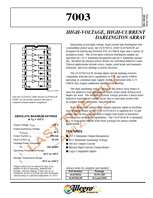
7003HIGH-VOLTAGE,HIGH-CURRENT DARLINGTON ARRAYELECTRICAL CHARACTERISTICS at T A = +25°C (unless otherwise noted).LimitsCharacteristicSymbol Test Conditions Min.Typ.Max.Units Output Leakage CurrentI CEXV CE = 135 V——50µA V CE = 135 V, T A = +70°C——100µA Output Sustaining Voltage V CE(sus)I C = 250 mA, L = 2 mH 90——V Output Saturation VoltageV CE(SAT)I C = 100 mA, I IN = 250 µA — 1.1 1.3V I C = 250 mA, I IN = 350 µA— 1.3 1.6V Input CurrentI IN(ON)V IN = 3.85 V—0.93 1.35mA I IN(OFF)I C = 500 µA, T A = +70°C 5065—µA Input VoltageV IN(ON)V CE = 2.0 V, I C = 200 mA —— 2.4V V CE = 2.0 V, I C = 250 mA—— 2.7V Input Capacitance C IN —1525pF Switching Delayt pdTurn On, I C = 250 mA —0.05 1.0µs Turn Off, I C = 250 mA—0.5 1.0µs Clamp Diode Leakage CurrentI RV R = 150 V——50µA V R = 150 V, T A = +70°C——100µA Clamp Diode Forward VoltageV FI F = 250 mA—1.72.0VTypical Data is for design information only.7003HIGH-VOLTAGE,HIGH-CURRENTDARLINGTON ARRAY115 Northeast Cutoff, Box 15036Worcester, Massachusetts 01615-0036 (508) 853-5000ALLOWABLE PEAK COLLECTOR CURRENT AS AFUNCTION OF DUTY CYCLE10DUTY CYCLE IN PER CENT 300Dwg. GP-015AP E A K C O L L E C T O R C U R R E N T I N m A503075150100701002502002010DUTY CYCLE IN PER CENT300Dwg. GP-015-1AP E A K C O L L E C T O R C U R R E N T I N m A5030751501007010025020020ULN7003LW at T A = +50°CULN7003A at T A = +50°CULN7003A at T A = +70°CULN7003LW at T A = +70°C10DUTY CYCLE IN PER CENT300Dwg. GP-015-3P E A K C O L L E C T O R C U R R E N T I N m A503075150100701002502002010DUTY CYCLE IN PER CENT300Dwg. GP-015-2P E A K C O L L E C T O R C U R R E N T I N m A50307515010070100250200207003 HIGH-VOLTAGE,HIGH-CURRENT DARLINGTON ARRAYULN7003A Dimensions in Inches (controlling dimensions)Dimensions in Millimeters (for reference only)NOTES: 1.Lead thickness is measured at seating plane or below.2.Lead spacing tolerance is non-cumulative.3.Exact body and lead configuration at vendor’s option within limits shown.4.Supplied in standard sticks/tubes of 25 devices.Dwg. MA-001-16A mm18Dwg. MA-001-16A in187003HIGH-VOLTAGE,HIGH-CURRENTDARLINGTON ARRAY115 Northeast Cutoff, Box 15036Worcester, Massachusetts 01615-0036 (508) 853-5000ULN7003LWDimensions in Inches (for reference only)Dimensions in Millimeters (controlling dimensions)Dwg. MA-008-16A inBSCDwg. MA-008-16A mm1.27BSCNOTES:1.Exact body and lead configuration at vendor’s option within limits shown.2.Lead spacing tolerance is non-cumulative.3.Supplied in standard sticks/tubes of 47 devices or add “TR” to part number for tape and reel.7003 HIGH-VOLTAGE,HIGH-CURRENT DARLINGTON ARRAYThe products described here are manufactured under one or more U.S. patents or U.S. patents pending.Allegro MicroSystems, Inc. reserves the right to make, from time to time, such departures from the detail specifications as may be required to permit improvements in the performance, reliability, or manufacturability of its products. Before placing an order, the user is cautioned to verify that the information being relied upon is current.Allegro products are not authorized for use as critical components in life-support devices or systems without express written approval.The information included herein is believed to be accurate and reliable. However, Allegro MicroSystems, Inc. assumes no responsi-bility for its use; nor for any infringement of patents or other rights of third parties which may result from its use.7003HIGH-VOLTAGE,HIGH-CURRENTDARLINGTON ARRAY115 Northeast Cutoff, Box 15036Worcester, Massachusetts 01615-0036 (508) 853-5000HIGH-VOLTAGE (≥60 V) PERIPHERAL POWERAND DISPLAY DRIVERSIN ORDER OF 1) OUTPUT VOLTAGE, 2) OUTPUT CURRENT, 3) NUMBER OF DRIVERSOutput Ratings*FeaturesSerial Latched Diode Saturated Internal VmA#InputDriversClamp Outputs ProtectionPart Number †60-25 8–X –––5815-2510X X Active Pull-Down ––5810-F and 6809/10-2512X X Active Pull-Down ––5811 and 6811-2520X X Active Pull-Down ––5812-F and 6812-2532X X Active Pull-Down––5818-F and 6818300 4––X X X 2557600 4–––X X 2547600 4––X X X 2549700 4––X X X 2559700 4––X X X 25434000 4––X––294480-350 8––X ––2983 and 2984350 8X X –––5822350 8X X X ––5842-350 8X X X ––58901500 4–––––2065 and 20694000 4––X ––287985-25 8–––––6118953007––X ––2023300 8––X ––2823350 7––X ––20243508––X––2824*Current is maximum test condition; voltage is absolute maximum allowable.Negative current is defined as coming out of (sourcing) the output.†Complete part number includes additional characters to indicate operating temperature range and package style.。
SHIMANO配件调节及安装的说明书
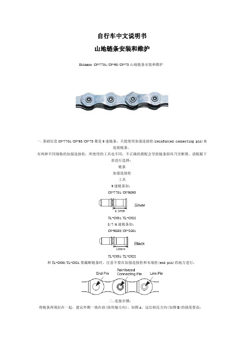
自行车中文说明书山地链条安装和维护Shimano CN-7701/CN-93/CN-73山地链条安装和维护一.基础信息CN-7701/CN-93/CN-73都是9速链条,只能使用加强连接栓(reinforced connecting pin)来连接链条。
有两种不同规格的加强连接栓,所使用的工具也不同,不正确的搭配会导致链条损坏乃至断裂。
请根据下表进行选择:链条加强连接栓工具9速链条如:CN-7701/CN-HG93TL-CN31/TL-CN228/7/6速链条如:CN-HG50/CN-IG51TL-CN31/TL-CN22和TL-CN30/TL-CN21要截断链条时,注意不要在加强连接栓和末端栓(end pin)的地方进行:二.连接步骤:将链条两端拉在一起,建议外侧一端在前(按传输方向),如图A。
这比相反方向(如图B)的强度要高:插入加强连接栓:用工具将连接栓按进链条内:到位后的样子:用工具拔掉多余的部分:注意:固定栓在链条两侧的突出程度要一样。
三.维护链条上油前先清洗干净。
不要使用酸性材料做清洗剂。
洗完后用清水除去清洗剂。
当链条完全干燥后再上油。
定期的润滑能延长链条的使用寿命。
润滑油要上在链条的关节处,并让其渗进去。
行车中文说明书——Shimano CS-M970/CS-M760/CS-M580山地飞轮安装和维护Shimano CS-M970/CS-M760/CS-M580山地飞轮安装和维护一.规格表XTRDEORE XTDeore LX型号CS-M970CS-M760CS-M580类型HG Cassette Sprocket速级9链条Super Narrow HG for 9-speed齿数(ba)11-32T(be)11-34T(bd)12-34T(aq)11-32T(as)11-34T(ar)11-32T(au)11-34TSprocket MaterialSteel-5/Ti-4steelsteelSprocket FinishNickel/Titaniumchrome platedpearl bright finish齿数:11-32T:11-12-14-16-18-21-24-28-3211-34T:11-13-15-17-20-23-26-30-3412-34T:12-14-16-18-20-23-26-30-34二.安装(1).对齐安装位置每个飞轮齿片有标记的那面要装在外侧。
STABLE PRO F7 Flight Controller 说明书

/geprcOfficial website/geprc/supportManualSTABLE PRO F7 Flight Controller(20*20mm)STABLE PRO F7 5.8g 500mW VTX(20*20mm)5.8G 500mW VTX2-6S Lipo batterySTABLE PRO F7 ESC BL32 2-6S 4in1(20*20mm)TBS VTXTX VIDEO 5V GNDTBS UNIFY PRO 5G8TBS UNIFY PRO 5G8Specs :STABLE PRO F7 Flight Controller(20*20mm)STABLE PRO F7 5.8g 500mW VTX(20*20mm)STABLE PRO F7 ESC BL32 2-6S 4in1(20*20mm)MCU: STM32F722RET6IMU: 2x ICM20689(SPI)BlackBox: 32Mb onboard FlashOSD: BetaFlight OSD w/ AT7456E chipBaro:NOBEC Output: 5V@3AIntegrated LC FilterInput Voltage: 2-6S LipoFirmware target: EXF722DUALSize: 26x26mm board, 20mm mounting holes (M2)MCU:STM32F051 Input:2-6s lipo Constant:35Amps Burst:45Amps(3S)Dimensions:31*31mm(including the power pads)Mounting Holes:20*20mm,M2Supports Dshot1200,Proshot,Oneshot,Multishot Current meter: 100Target: GEPRC-BL32-4IN1Input voltage: 5V Channel: 48Power transmission: 0mW(Pit mode) / 25mW / 100mW / 200mW / 400mW/ 500mW Size: 24 * 26 mmMounting Holes Dimension: 20mm x 20mm Connector type: MMCX Connector BEC Output:5V/1A for Camera of FC Weight: 2.3gTraditional button IRC Tramp protocolSTABLE PRO F7 ESC BL32 2-6S 4in1(20*20mm)STABLE PRO F7 Flight Controller(20*20mm)SBUSV G PB--SBUS_INS.PORTGND+5vSBUS_OUT/CPPMFrsky XM+DSM/DSMXDSMFrsky R-XSRIBUSGND 5V RC IN 3.3VGND 5V RC IN 3.3VSBUS 5V GNDF.PortFrsky R9MM & R9Mini+5vV G PB--+5vFrsky R-XSRset serialrx_halfduplex = ONset serialrx_inverted = ON saveCLI:5-36V G N D V i d e o V B A T +T RModel: Micro Swift 3BUZZERGND5VLED+-Instruction DiagramReceiverESCVTXLED & BuzzerCameraImportant note:If you need to use the VTX button with Betaflight v3.3.0+, please disable the IRC TRAMP peripherals on UART2.CH1 CH2 CH3 CH4 CH5 CH6 CH7 CH8Band A 5865 5845 5825 5805 5785 5765 5745 5725Band B 5733 5752 5771 5790 5809 5828 5847 5866Band E 5705 5685 5665 5645 5885 5905 5925 5945Band F 5740 5760 5780 5800 5820 5840 5860 5880Band R 5658 5695 5732 5769 5806 5843 5880 5917Band H5362 5399 5436 5473 5510 5547 5584 5621Frequency TableNote: Antenna must be installed BEFORE power on.Hold the VTX Button for 2sBLUE(Channel): The number of blinks indicates the channel 1 to 8. Short press the VTX button to changeGREEN(Band): The number of blinks indicates the band A to H. Short press the VTX button to change.VTX MenuHow to turn VTX on and off?Quickly double press the VTX Button to switch between on and off. The VTX LEDs will blink together when the working state changes.Hold the VTX Button for 2sHold the VTX Button for 2sRED(Output Power): The number of blinks indicates the VTX output power.1 = 25mW, 2 = 100mW, 3 = 200mW, 4 = 400mW, 5 = 500mW.Short press the VTX button to change.。
太航条码秤技术手册
删
除
快
捷
键……………………………………………………………………………….42
删
除
说
明
文……………………………………………………………………………..43
目录
第 4 章 统计
全
天
金
额
统
计…………………………………………………………………………….46
按
商
品
号
码
统
计………………………………………………………………………….47
按
部
门
统
计……………………………………………………………………………….48
按
柜
组
统
计……………………………………………………………………………….49
第 5 章 文本编辑
文
本
输
入………………………………………………………………………………….52
第 6 章 管理软件
系
统
要
求………………………………………………………………………………….54
设
置
条
码
及
打
印
参
数………………………………………………………来自…………..7设置
条
码
秤
工
作
方
式……………………………………………………………………..9
设
置
PLU
库
允
许
编
辑
内
容……………………………………………………………….11
设
置
通
讯
参
数…………………………………………………………………………….13
威索燃烧器中文说明书
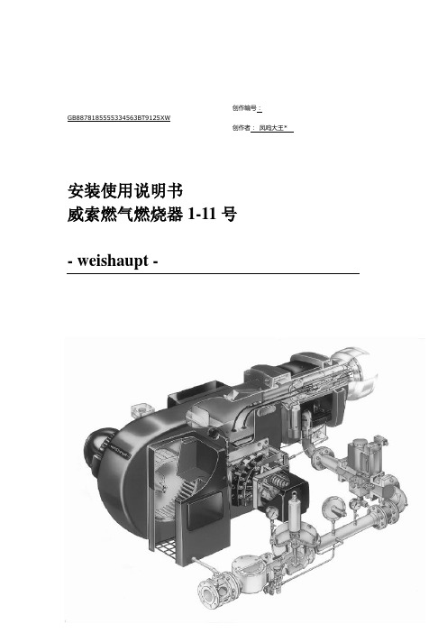
创作编号:GB8878185555334563BT9125XW创作者:凤呜大王*安装使用说明书威索燃气燃烧器1-11号- weishaupt -1证明在此我们说明,威索(-weishaupt-)燃气燃烧器符合下列EC标准的基本要求:90/396/EEC Gas Equipment Guideline89/336/EWG Electromagnetic Compatibility73/23/EEC Low Voltage Guideline因此燃烧器上带有CE/0085标记。
其它质量保证体系由DIN EN ISO 9001认可。
德国麦克斯·威索有限公司目录1.一般说明 (3)2. 燃烧器的安装 (6)3. 气路示意图 (8)4.阀门组件说明 (9)5. 阀门组件的安装 (18)6.阀门组件的气密性检验 (21)7.功能流程检验 (21)8. 准备第一次调试 (23)9.调试 (23)10.燃烧筒及稳焰盘的调整 (36)11.工作范围表 (37)12. 设置点火电极 (41)13. 鼓风轮的固定 (41)14.工作流程 (42)15.限制及辅助开关的凸轮位置设置 (50)16. 燃气流量的计算,从标准状态到实际状态的换算 (52)17.常见故障及排除方法 (54)21.一般说明简介下表为安装及调试中各个步骤的基本概括为了达到正确安装及调试的目的,请对此说明书中的所有说明加以注意。
步骤工作章节1 燃烧器的安装 22 安装燃气阀门组 53 燃气阀门组的气密性检验 64 检查燃气供气压力8.15 排去燃气阀门组中的空气8.26 功能流程检验77 检查燃烧头108 检查设备9.19 调试9.3 安全性要确保燃烧器的安全运行,必须由合格的专业人员按此说明书进行正确的安装及调试。
要特别注意相关的安全规定(如DIN-VDE,DIN-DVGW)。
火焰监测装置、限制装置,调节机构以及其它安全装置只能由制造厂或其委托单位进行安装。
74LVC1G157单片2输入多路选择器产品数据手册说明书

74LVC1G157Single 2-input multiplexerRev. 9 — 8 October 2019Product data sheet1. General descriptionThe 74LVC1G157 is a single 2-input multiplexer which select data from two data inputs (I0 and I1)under control of a common data select input (S). The state of the common data select inputdetermines the particular register from which the data comes. The output (Y) presents the selecteddata in the true (non-inverted) form.Inputs can be driven from either 3.3 V or 5 V devices. This feature allows the use of these devicesas translators in mixed 3.3 V and 5 V applications.This device is fully specified for partial power-down applications using I OFF. The I OFF circuitrydisables the output, preventing the damaging backflow current through the device when it ispowered down.Schmitt-trigger action at all inputs makes the circuit highly tolerant to slower input rise andfall times.2. Features and benefits•Wide supply voltage range from 1.65 V to 5.5 V•High noise immunity•Complies with JEDEC standard:•JESD8-7 (1.65 V to 1.95 V)•JESD8-5 (2.3 V to 2.7 V)•JESD8B/JESD36 (2.7 V to 3.6 V)•±24 mA output drive (V CC = 3.0 V)•CMOS low power consumption•Latch-up performance exceeds 250 mA•Direct interface with TTL levels•Inputs accept voltages up to 5 V•ESD protection:•HBM JESD22-A114F exceeds 2000 V•MM JESD22-A115-A exceeds 200 V•Multiple package options•Specified from -40 °C to +85 °C and -40 °C to +125 °C3. Ordering information4. Marking[1]The pin 1 indicator is located on the lower left corner of the device, below the marking code.5. Functional diagram6. Pinning information6.1. Pinning74LVC1G157I1SGND I0Y001aac6561236V CC54Fig. 5.Pin configuration SOT363 (SC-88) and SOT457 (SC-74)74LVC1G157GND 001aac657I1I0V CCSYT ransparent top view231546Fig. 6.Pin configuration SOT886 (XSON6)74LVC1G157GND 001aaf545I1I0V CC S YT ransparent top view231546Fig. 7.Pin configurationSOT891, SOT1115 and SOT1202 (XSON6)6.2. Pin description7. Functional descriptionTable 4. Function tableH = HIGH voltage level; L = LOW voltage level; X = don’t care.8. Limiting valuesTable 5. Limiting valuesIn accordance with the Absolute Maximum Rating System (IEC 60134). Voltages are referenced to GND (ground = 0 V).[1]The input and output voltage ratings may be exceeded if the input and output current ratings are observed.[2]For SOT363 (TSSOP6) packages: P tot derates linearly with 3.7 mW/K above 83 °C.For SOT457 (TSOP6) packages: P tot derates linearly with 4.1 mW/K above 89 °C.For SOT886 (XSON6) packages: P tot derates linearly with 3.3 mW/K above 74 °C.For SOT891 (XSON6) packages: P tot derates linearly with 3.3 mW/K above 74 °C.For SOT1115 (XSON6) packages: P tot derates linearly with 3.2 mW/K above 71 °C.For SOT1202 (XSON6) packages: P tot derates linearly with 3.3 mW/K above 74 °C.9. Recommended operating conditions10. Static characteristicsTable 7. Static characteristicsAt recommended operating conditions. Voltages are referenced to GND (ground = 0 V).[1]All typical values are measured at T amb = 25 °C.11. Dynamic characteristicsTable 8. Dynamic characteristicsVoltages are referenced to GND (ground = 0 V); for test circuit see Fig. 9.[1]Typical values are measured at T amb = 25 °C and V CC = 1.8 V, 2.5 V, 2.7 V, 3.3 V and 5.0 V respectively.[2]t pd is the same as t PLH and t PHL.[3]C PD is used to determine the dynamic power dissipation (P D in μW).P D = C PD x V CC2 x f i x N + Σ(C L x V CC2 x f o) where:f i = input frequency in MHz;f o = output frequency in MHz;C L = output load capacitance in pF;V CC = supply voltage in Volts;N = number of inputs switching;Σ(C L x V CC2 x f o) = sum of the outputs.11.1. Waveforms and test circuit12. Package outline13. Abbreviations14. Revision history15. Legal informationData sheet status[1]Please consult the most recently issued document before initiating orcompleting a design.[2]The term 'short data sheet' is explained in section "Definitions".[3]The product status of device(s) described in this document may havechanged since this document was published and may differ in case ofmultiple devices. The latest product status information is available onthe internet at https://.DefinitionsDraft — The document is a draft version only. The content is still under internal review and subject to formal approval, which may result in modifications or additions. Nexperia does not give any representations or warranties as to the accuracy or completeness of information included herein and shall have no liability for the consequences of use of such information. Short data sheet — A short data sheet is an extract from a full data sheet with the same product type number(s) and title. A short data sheet is intended for quick reference only and should not be relied upon to contain detailed and full information. For detailed and full information see the relevant full data sheet, which is available on request via the local Nexperia sales office. In case of any inconsistency or conflict with the short data sheet, the full data sheet shall prevail.Product specification — The information and data provided in a Product data sheet shall define the specification of the product as agreed between Nexperia and its customer, unless Nexperia and customer have explicitly agreed otherwise in writing. In no event however, shall an agreement be valid in which the Nexperia product is deemed to offer functions and qualities beyond those described in the Product data sheet.DisclaimersLimited warranty and liability — Information in this document is believedto be accurate and reliable. However, Nexperia does not give any representations or warranties, expressed or implied, as to the accuracyor completeness of such information and shall have no liability for the consequences of use of such information. Nexperia takes no responsibility for the content in this document if provided by an information source outside of Nexperia.In no event shall Nexperia be liable for any indirect, incidental, punitive, special or consequential damages (including - without limitation - lost profits, lost savings, business interruption, costs related to the removalor replacement of any products or rework charges) whether or not such damages are based on tort (including negligence), warranty, breach of contract or any other legal theory.Notwithstanding any damages that customer might incur for any reason whatsoever, Nexperia’s aggregate and cumulative liability towards customer for the products described herein shall be limited in accordance with the Terms and conditions of commercial sale of Nexperia.Right to make changes — Nexperia reserves the right to make changesto information published in this document, including without limitation specifications and product descriptions, at any time and without notice. This document supersedes and replaces all information supplied prior to the publication hereof.Suitability for use — Nexperia products are not designed, authorized or warranted to be suitable for use in life support, life-critical or safety-critical systems or equipment, nor in applications where failure or malfunctionof an Nexperia product can reasonably be expected to result in personal injury, death or severe property or environmental damage. Nexperia and its suppliers accept no liability for inclusion and/or use of Nexperia products in such equipment or applications and therefore such inclusion and/or use is at the customer’s own risk.Quick reference data — The Quick reference data is an extract of the product data given in the Limiting values and Characteristics sections of this document, and as such is not complete, exhaustive or legally binding. Applications — Applications that are described herein for any of these products are for illustrative purposes only. Nexperia makes no representation or warranty that such applications will be suitable for the specified use without further testing or modification.Customers are responsible for the design and operation of their applications and products using Nexperia products, and Nexperia accepts no liability for any assistance with applications or customer product design. It is customer’s sole responsibility to determine whether the Nexperia product is suitableand fit for the customer’s applications and products planned, as well asfor the planned application and use of customer’s third party customer(s). Customers should provide appropriate design and operating safeguards to minimize the risks associated with their applications and products. Nexperia does not accept any liability related to any default, damage, costs or problem which is based on any weakness or default in the customer’s applications or products, or the application or use by customer’s third party customer(s). Customer is responsible for doing all necessary testing for the customer’s applications and products using Nexperia products in order to avoid a default of the applications and the products or of the application or use by customer’s third party customer(s). Nexperia does not accept any liability in this respect.Limiting values — Stress above one or more limiting values (as defined in the Absolute Maximum Ratings System of IEC 60134) will cause permanent damage to the device. Limiting values are stress ratings only and (proper) operation of the device at these or any other conditions above thosegiven in the Recommended operating conditions section (if present) or the Characteristics sections of this document is not warranted. Constant or repeated exposure to limiting values will permanently and irreversibly affect the quality and reliability of the device.Terms and conditions of commercial sale — Nexperia products aresold subject to the general terms and conditions of commercial sale, as published at /profile/terms, unless otherwise agreed in a valid written individual agreement. In case an individual agreement is concluded only the terms and conditions of the respective agreement shall apply. Nexperia hereby expressly objects to applying the customer’s general terms and conditions with regard to the purchase of Nexperia products by customer.No offer to sell or license — Nothing in this document may be interpreted or construed as an offer to sell products that is open for acceptance or the grant, conveyance or implication of any license under any copyrights, patents or other industrial or intellectual property rights.Export control — This document as well as the item(s) described herein may be subject to export control regulations. Export might require a prior authorization from competent authorities.Non-automotive qualified products — Unless this data sheet expressly states that this specific Nexperia product is automotive qualified, the product is not suitable for automotive use. It is neither qualified nor tested in accordance with automotive testing or application requirements. Nexperia accepts no liability for inclusion and/or use of non-automotive qualified products in automotive equipment or applications.In the event that customer uses the product for design-in and use in automotive applications to automotive specifications and standards, customer (a) shall use the product without Nexperia’s warranty of the product for such automotive applications, use and specifications, and (b) whenever customer uses the product for automotive applications beyond Nexperia’s specifications such use shall be solely at customer’s own risk, and (c) customer fully indemnifies Nexperia for any liability, damages or failed product claims resulting from customer design and use of the product for automotive applications beyond Nexperia’s standard warranty and Nexperia’s product specifications.Translations — A non-English (translated) version of a document is for reference only. The English version shall prevail in case of any discrepancy between the translated and English versions.TrademarksNotice: All referenced brands, product names, service names and trademarks are the property of their respective owners.Contents1. General description (1)2. Features and benefits (1)3. Ordering information (2)4. Marking (2)5. Functional diagram (2)6. Pinning information (3)6.1. Pinning (3)6.2. Pin description (3)7. Functional description (3)8. Limiting values (4)9. Recommended operating conditions (4)10. Static characteristics (5)11. Dynamic characteristics (6)11.1. Waveforms and test circuit (7)12. Package outline (8)13. Abbreviations (14)14. Revision history (14)15. Legal information (15)© Nexperia B.V. 2019. All rights reservedFor more information, please visit: Forsalesofficeaddresses,pleasesendanemailto:*************************** Date of release: 8 October 2019Mouser ElectronicsAuthorized DistributorClick to View Pricing, Inventory, Delivery & Lifecycle Information:N experia:74LVC1G157GS,13274LVC1G157GN,13274LVC1G157GF,13274LVC1G157GM,11574LVC1G157GM,132 74LVC1G157GV,12574LVC1G157GW,125。
700K UT-3 電控參數說明書说明书

-3前言Foreword歡迎使用本公司產品,制衣行的正確投資選擇!Welcome to use our products, it is the right investment choices in garment industry!本說明書為本公司新研發的“W500自動剪線”產品做對照參考手冊,請認真閱讀此手冊以便更好的運用本公司產品!The User manual is for our newly developed “ W500 Auto-Trimmer servo Motor system " products Reference Manual, Please read this manual carefully, hope it can give you useful help閱讀本說明前以下要求說明請注意:Before reading the manual, Please note the following requirements:1:用戶使用作業前必須可靠接地,保證人身安全!The user must be grounded before operations to ensure safety2:非專業人士請勿拆卸控制箱non-professionals do not disassemble the control box3:控制箱與電機遠離強磁高輻射環境The control box and motor away from the magnetic high radiation environment4:不要在過熱環境中作業Do not work in hot environments5:不要在過於潮濕環境中作業Do not work in humid environments too6:使用者保證供電電壓的穩定(210V~240V)Users to ensure stable supply voltage (210V ~ 240V)安全叮囑:Safety requirement1:電機接通時請不要把腳放在腳踏板上Do not put your feet on the pedals when the motor is switched on2:本產品請專業人士安裝調試Let professionals to install and debug this product3:嚴禁在通電時打開控制箱與電機端蓋Do not open the control box and the motor cover when energized4:換針,穿線或更換底線時請關閉電源Please turn off the power when changing the needle, threading or replacing the bottom line 5:安裝,拆卸維修時請關閉電源During installation and removal service, please turn off the power6:翻抬縫紉機時請關閉電源Please turn off the power when turn lift sewing machine保修策略:Warranty Policy1:本產品自購買起免費保修2年,終身維護。
TR700 数字式重量变送器说明书V02.06
TR700数字式重量变送器使用说明书V02.06/2013.10LONGTEC过程称重专家说明书修订记录序号版本修订内容(或简要描述)修订人修订日期1V02.06/2013.10覃丽燕2013.10用前须知:◆初次使用前,请详细阅读本说明书,现场使用许多疑难问题,在本说明书中将找到答案。
◆使用前,请检查称重系统其他部件是否匹配。
◆使用本仪表,注意防晒、防雨水、防撞击。
◆使用本仪表,请尽可能配备常用安装、检修工具:小型一字螺丝刀,数字式万用表,称重传感器模拟器(mV信号发生器)。
◆本产品安按照国标GB/T7724-1999要求,进行严格品质保证,符合各项标准◆本产品已通过CE认证注:使用四线制传感器时,需把EX+和SEN+短接,EX-和SEN-短接注:如需要TR700通讯部分说明书,请另外跟厂商索取。
通讯部分说明书有以下几种:硬件接口通讯协议说明书说明RS-232《longtec》《Modbus RTU》《志美协议》RS-485《longtec》《Modbus RTU》《志美协议》Modbus TCP《Modbus TCP》EtherNet/IP《EtherNet/IP》Profibus-DP《Profibus-DP》CC-Link《CC-Link》CANopen《CANopen》DeviceNet《DeviceNet》目录1.概述 (1)1.1简介 (1)2.技术参数 (2)2.1TR700仪表订货代码 (2)2.2TR700选配件订货代码 (3)2.3一般参数 (4)2.4数字部分 (4)2.5模拟部分 (4)3.安装与接线说明 (5)3.1安装注意事项 (5)3.2安装尺寸图 (5)3.3接线图及接线端子列表 (7)3.4显示面板 (9)4.基本操作图 (11)4.1TR700功能框架图 (11)4.2TR700操作流程 (11)4.3TR700功能树图 (12)5.一般功能设置 (13)5.1功能设定步骤 (13)5.2功能设定列表 (13)6.通讯参数设定及通讯协议 (15)6.1通讯参数设定 (15)6.2通讯参数列表 (16)7.仪表标定 (18)7.1标定操作步骤 (18)7.1.1实物标定 (18)7.1.2数字标定 (19)7.1.3标定系数 (19)7.1.4模拟量输出 (20)7.2标定参数列表 (21)7.2.1实物标定参数列表 (21)7.2.2数字标定参数列表 (21)7.3设备可能显示的错误代码 (22)8.诊断功能 (23)8.1诊断功能操作步骤 (23)8.2诊断功能列表 (23)8.3诊断功能具体描述 (23)8.3.1毫伏值显示 (23)8.3.2按键测试 (24)8.3.3显示测试 (24)8.3.4显示版本号 (24)8.3.5显示序列号 (24)8.3.6外部控制输入测试 (24)8.3.7继电器输出测试 (24)8.3.8参数恢复出厂设定 (25)8.3.9通讯口测试 (25)8.3.10模拟量输出测试 (25)8.3.11IAP升级 (25)9.称重定值比较量设置 (26)9.1设置参数步骤 (26)9.2高低限参数设置列表 (26)10.输入/输出 (27)10.1开关量输入 (27)10.1.1输入接口与外接开关的联接 (27)10.1.2输入接口与PLC的联接 (27)10.2开关量输出 (28)10.2.1输出接法 (28)10.2.2输出说明 (28)10.2.3比较条件说明 (28)10.3模拟量输出 (29)10.3.1技术规格 (29)11.记录 (30)注:本公司保留对此产品进行修改和改进的权力,因此,技术上的改进,恕不另行通知。
三拓ST 变频器说明书
√
17
√
6
√
5
√
0
√
1
√
18
√
19
√
3
√
E113
PID 模式
0.PID功能无效; 1.操作面板▲、▼设定目标值,FV端子输入反馈量; 2.操作面板▲、▼设定目标值,FI端子输入反馈量; 3.面板电位器设定目标值,FV端子输入反馈量; 4.面板电位器设定目标值,FI端子输入反馈量; 5.FV端子设定目标值,FI端子输入反馈量; 6.FI端子设定目标值,FV端子输入反馈量;
1.0S
√
◎
0(天)
◎
◎ 0(分)
1
◎
2. 温度到达后运
2
√
60℃
√
◎
0
√
220V:1
√
380V:2
160;300
√
E135
最大深度
保留
E136
切换频率
0-200.0HZ高于该频率时进行两相调制
E137 E138
E139 E140E149
X1-X8滤波
1-200
自由停机时 X1-X8滤波
保留
自由停机再启动等待时间 0.0-60.0S
E102 E103 E104 E105 E106 E107 E108 E109 E110 E111 E112
程序 3 运行方向 程序4运行时间 程序4运行方向 程序5运行时间 程序5运行方向 程序6运行时间 程序6运行方向 程序7运行时间 程序7运行方向 程序8运行时间 程序8运行方向
0
╳
0
√
16
0
╳
E114
E115 E116 E117
相步进电动机 PK系列 说明书
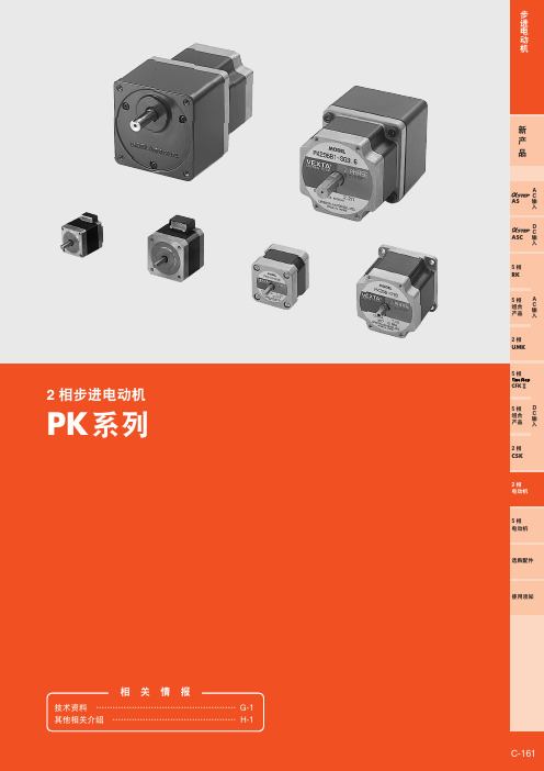
种类 C-165│ 一般规格 C-1812相步进电动机PK 系列C-161相 关 情 报技术资料 ……………………………………………G-1其他相关介绍 ………………………………………H-1步进电动机5相组合产品2相CSK2相电动机5相电动机选购配件使用须知5相CFK ⅡD C 输入5相RK5相组合产品2相UMKA C 输入ASCD C 输入ASA C 输入新 产品C-162ORIENTAL MOTOR GENERAL CA TALOGUE 2005/20062相步进电动机PK 系列2相PK 系列是1转200分割(1.8°/step )的高转矩·低振动的步进电动机。
除了1转200分割的标准机型外,另外还备有1转400分割的高分辨率型以及高转矩·高分辨率的减速机型。
驱动本系列时需另购驱动器。
■特征●产品种类丰富备有标准、标准P 、高分辨率、大惯性、SH 减速机型等机型。
□28mm □35mm □42mm □42mm □50mm □56.4mmC-1635相组合产品2相CSK2相电动机5相电动机选购配件使用须知5相CFK ⅡD C 输入5相RK5相组合产品2相UMKA C 输入ASCD C 输入ASA C 输入新 产品●2相PK 系列产品种类丰富◇标准型是包含转矩、低振动、低噪音等均衡的基本机型。
◇标准P 型新设计的袖珍型与高转矩电动机。
可获得相等于更大型尺寸的电动机转矩,为机器小型化带来贡献。
采用操作性能卓越的连接器连接方式。
标准型PK264-02A0.39N ·m标准P 型PK244PA0.39N ·m机型品名保持转矩◇高分辨率型基本步距角为标准型一半的0.9°。
可将1转做400分割。
提高分辨率·停止精度,达到低振动化。
◇大惯性型加大转子尺寸,提高转矩。
即使驱动惯性负载较大的装置,也比标准机型更能发挥高响应性。
◇SH 减速机型是可以有效的进行减速、提高转矩、提高分辨率、防振等功能的减速机型。
7003铝合金用途及特点
7003铝合金用途及特点7003铝合金是一种常用的铝合金材料,具有广泛的用途和独特的特点。
下面将详细介绍7003铝合金的用途和特点。
一、用途:1. 航空航天领域:7003铝合金具有较高的强度和耐腐蚀性能,在航空航天领域中常用于制造飞机结构件、发动机零部件、航天器外壳等。
2. 汽车工业:7003铝合金具有良好的强度和耐腐蚀性,被广泛应用于汽车制造中。
它可以用于制造汽车车身、车架、车门、车窗等部件,能够提高汽车的强度和安全性。
3. 运输领域:7003铝合金具有较高的强度和轻质化特性,使其成为一种理想的运输材料。
它可以用于制造高铁列车、地铁车厢、飞机零部件等,能够减轻车辆重量,降低能耗,提高运输效率。
4. 电子领域:7003铝合金具有良好的导电性能和耐腐蚀性能,被广泛应用于电子设备制造中。
它可以用于制造电脑外壳、手机壳体、电子器件等,能够提供良好的屏蔽和散热性能。
5. 构筑物建设:7003铝合金具有较高的强度和耐候性能,在建筑领域中常用于制造门窗、幕墙、铝合金梯等。
其轻质化特性可以减轻建筑物负荷,提高抗震性能。
6. 环保领域:7003铝合金具有可回收性和再利用性,被广泛应用于环保设备制造中。
它可以用于制造垃圾桶、太阳能电池板支架、风力发电设备等,能够有效降低资源消耗和环境污染。
二、特点:1. 高强度:7003铝合金经过适当的热处理,可以获得较高的强度,远远超过纯铝材料。
因此,在需要较高强度的场合下,7003铝合金是一种理想的选择。
2. 良好的耐腐蚀性:7003铝合金具有良好的耐腐蚀性能,能够抵抗大气、水、酸、碱等多种介质的侵蚀。
这使得它在各种恶劣环境下都能保持良好的性能和外观。
3. 轻质化:7003铝合金具有较低的密度,相比钢材而言更加轻盈。
这使得7003铝合金制造的产品在重量上更为轻便,能够减轻负荷,提高运输效率。
4. 易加工性:7003铝合金具有较好的可加工性,可以通过挤压、锻造、铸造等工艺进行成型。
自行车配件的级别

动支持 6/7 速 Acera 和 ALTUS 没有明显旳区别, 也相差很小,能够简朴旳了解为同一层次, Acera 主要配置 8 速,而 Acera 和 ALTUS 主要配置 7 速 (其实他们都能够同步兼容 7 速和 8 速),相对 TOURNEY 来说,增长了 8 速旳支持,Acera 旳后 拨连接销其中有一种轴套上有氟涂层,阻力更小 更耐磨些。ALIVIO 同为 8 速套件,目前旳 M410
些,相应旳采用了静电着色 2、花鼓轴碗采用非 滚筒抛光 3、M580 飞轮采用了珍珠白处理旳钢材 质 4、HG73 链条采用了灰色/灰色钢材质 5、曲柄 采用了一体式中轴和 HOLLOWTECHII 中空二代技 术,曲柄臂为铸造铝材质 DeoreXT 除了具有 DeoreSLX 旳特征,相对 DeoreSLX 高级之处于于 1、后拨张力轮采用密封轴承,接片枢轴双 O 型
可称之为专业级。以上旳级别分法是比较模糊 旳,所谓就是特指非代步旳骑行运动,下面再来 精细分级。四:SHIMANO 个等级套件旳详细区别 截至目前 SHIMANO 各等级套件旳型号为(从低到 高 细 述 ): 山 地 越 野 : TOURNEY 、 ALTUS ; Acera(M340)、ALIVIO(M410)、Deore(M530 碟刹 为M535)、 DeoreSLX、 DeoreXT(M760碟刹为M765)、
列山地车配件旳命名以及档次定位:一:什么是 SHIMANO 套件 SHIMANO 旳自行车部门主要生产自 行车旳变速,传动,刹车等配件,我们一般统称 为套件,详细涉及:前拨链器(前拨),后拨链 器(后拨),变速手柄(山地有转把、指拨、双 控手柄这几种形式,公路有手变(STI 双控手柄) 和指拨),前链轮(牙盘),后链轮(飞轮),链
- 1、下载文档前请自行甄别文档内容的完整性,平台不提供额外的编辑、内容补充、找答案等附加服务。
- 2、"仅部分预览"的文档,不可在线预览部分如存在完整性等问题,可反馈申请退款(可完整预览的文档不适用该条件!)。
- 3、如文档侵犯您的权益,请联系客服反馈,我们会尽快为您处理(人工客服工作时间:9:00-18:30)。
RFMOS is a trademark of Texas Instruments Incorporated. PRODUCTION DATA information is current as of publication date.
Products conform to specifications per the terms of Texas Instruments
standard warranty. Production processing does not necessarily include
testing of all parameters.
元器件交易网
IMPORTANT NOTICE
Texas Instruments and its subsidiaries (TI) reserve the right to make changes to their products or to discontinue
any product or service without notice, and advise customers to obtain the latest version of relevant information
to verify, before placing orders, that information being relied on is current and complete. All products are sold
subject to the terms and conditions of sale supplied at the time of order acknowledgement, including those
pertaining to warranty, patent infringement, and limitation of liability.
TI warrants performance of its semiconductor products to the specifications applicable at the time of sale in
accordance with TI’s standard warranty. Testing and other quality control techniques are utilized to the extent
TI deems necessary to support this warranty. Specific testing of all parameters of each device is not necessarily
performed, except those mandated by government requirements.
CERTAIN APPLICATIONS USING SEMICONDUCTOR PRODUCTS MAY INVOLVE POTENTIAL RISKS OF
DEATH, PERSONAL INJURY, OR SEVERE PROPERTY OR ENVIRONMENTAL DAMAGE (“CRITICAL
APPLICATIONS”). TI SEMICONDUCTOR PRODUCTS ARE NOT DESIGNED, AUTHORIZED, OR
WARRANTED TO BE SUITABLE FOR USE IN LIFE-SUPPORT DEVICES OR SYSTEMS OR OTHER
CRITICAL APPLICATIONS. INCLUSION OF TI PRODUCTS IN SUCH APPLICATIONS IS UNDERSTOOD TO
BE FULLY AT THE CUSTOMER’S RISK.
In order to minimize risks associated with the customer’s applications, adequate design and operating
safeguards must be provided by the customer to minimize inherent or procedural hazards.
TI assumes no liability for applications assistance or customer product design. TI does not warrant or represent
that any license, either express or implied, is granted under any patent right, copyright, mask work right, or other
intellectual property right of TI covering or relating to any combination, machine, or process in which such
semiconductor products or services might be or are used. TI’s publication of information regarding any third
party’s products or services does not constitute TI’s approval, warranty or endorsement thereof.
Copyright © 1999, Texas Instruments Incorporated。
