Vishay推出新款共漏极双N沟道60 V MOSFET
意法半导体电机控制参考指南说明书
电机控制3 意法半导体电机控制生态系统4 PMSM & BLDC电机8 3相感应电机(ACIM)12 步进电机14 直流有刷电机16 通用电机18 开关磁阻电机19 微控制器25 STM32电机控制生态系统29 电机驱动器IC39 电源模块44 功率MOSFET46 IGBT47 600-650 V IGBT系列48 1200 V IGBT系列49 二极管 & 整流器50 晶闸管、双向可控硅和交流开关 52 MOSFET和IGBT栅极驱动器56 碳化硅和氮化镓栅极驱动器58 信号调理ST对电机控制的承诺推进了环保革命。
在环保革命理念的指引下,电机控制正向着更高效电机和驱动器的方向快速发展。
此外,为了支持新技术的市场占有率,需要以最低成本提高集成度,同时提升安全性和可靠性。
ST致力于电机控制方面的研究已有20余年,是最早意识到这些趋势的公司。
意法半导体正通过一系列的创新突飞猛进,诸如集成式智能功率模块和系统级封装、单片式电机驱动器、快速高效的功率开关、具有电压暂态保护功能的可控硅、以及功能强大且安全的微控制器等。
无论您使用哪种电机技术(从传统的和坚固的,到最现代的和最高效的),ST都能够提供合适的电子器件和完整的生态系统(包括一系列评估板、参考设计、固件和开发工具),以简化和加速设计流程。
保持最新资讯更多信息和最新材料,请访问ST网站的控制应用页面http:///motorcontrol3意法半导体电机控制PMSM &永磁同步电机和直流无刷电机因其更高效、运行更安静、更可靠等优点,正在越来越多的应用中替代直流有刷电机。
尽管结构不同,但所有三相永磁电机(BLDC、PMSM或PMAC)都是由脉冲宽度调制(PWM)的三相桥(三个半桥)驱动,以便采用频率幅度可变的电压和电流为电机供电。
为了提供最高水平设计灵活性,ST的产品组合包括面向高压和低压应用的特定产品,如单片驱动IC、功率MOSFET、IGBT、栅极驱动器、功率模块和专用微控制器,用于满足广泛的应用需求。
60n20场效应管参数

60n20场效应管参数英文回答:The 60n20 Mosfet is an n-channel power mosfet that is commonly used in high-power switching applications. It hasa maximum drain current of 60A and a maximum drain-source voltage of 200V. The 60n20 is also a very fast switching mosfet, with a typical turn-on time of 20ns and a typical turn-off time of 15ns.The 60n20 Mosfet is available in a variety of packages, including the TO-220, the TO-247, and the D2PAK. It is also available in a variety of pin configurations, including the TO-220AB, the TO-247AC, and the D2PAK-3.The 60n20 Mosfet is a very versatile device that can be used in a wide variety of applications. It is commonly used in high-power switching applications, such as motor control, power supplies, and inverters. It can also be used in low-power switching applications, such as audio amplifiers andlogic gates.Here is a summary of the key features of the 60n20 Mosfet:Maximum drain current: 60A.Maximum drain-source voltage: 200V.Typical turn-on time: 20ns.Typical turn-off time: 15ns.Available in a variety of packages and pin configurations.中文回答:60n20场效应管是一种n沟道功率场效应管,通常用于高功率开关应用。
VN10KC-T1中文资料
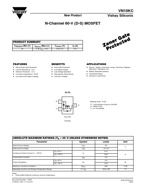
VN10KCVishay SiliconixNew ProductDocument Number: 70967S-04279—Rev . C, 16-Jul-0111-1N-Channel 60-V (D-S) MOSFETFEATURESBENEFITSAPPLICATIONSD Zener Diode Input Protected D Low On-Resistance: 3 W D Ultralow Threshold: 1.2 VD Low Input Capacitance: 38 pF DLow Input and Output LeakageD Extra ESD Protection D Low Offset Voltage D Low-Voltage Operation D High-Speed, Easily Driven DLow Error VoltageD Drivers: Relays, Solenoids, Lamps, Hammers, Displays,Memories, Transistors, etc.D Battery Operated Systems D Solid-State Relays D Inductive Load DriversVN10KCG S DTop View SC-59Marking Code: F1wllF1 = Part Number Code for VN10KC w = Week Code ll = Lot TraceabilityNotesa.Pulse width limited by maximum junction temperature.VN10KCVishay Siliconix New Product 11-2Document Number: 70967 S-04279—Rev. C, 16-Jul-01Notesa.For DESIGN AID ONLY, not subject to production testing.VNDP06b.Pulse test: PW v300 m s duty cycle v2%.c.Switching time is essentially independent of operating temperature.VN10KCVishay SiliconixNew ProductDocument Number: 70967S-04279—Rev . C, 16-Jul-0111-3Ohmic Region CharacteristicsOutput Characteristics for Low Gate DriveOn-Resistance vs. Drain CurrentNormalized On-Resistance vs. Junction TemperatureTransfer CharacteristicsOn-Resistance vs. Gate-to-Source VoltageV GS – Gate-Source Voltage (V)V GS – Gate-Source Voltage (V)V DS – Drain-to-Source Voltage (V)V DS – Drain-to-Source Voltage (V)I D – Drain Current (A)T J – Junction Temperature (_C)1.0123450.80.60.40.2500.40.81.21.62.04030201000.50.40.300150.20.1234543000.21.0210.40.60.82.252.001.750.50–50–101501.501.2530701101.000.7570481216206540321I D – D r a i n C u r r e n t (m A )I D – D r a i n C u r r e n t (m A )I D – D r a i n C u r r e n t (A )r D S (o n ) – O n -R e s i s t a n c e ( Ω )r D S (o n ) – D r a i n -S o u r c e O n -R e s i s t a n c e ( Ω )r D S (o n ) – D r a i n -S o u r c e O n -R e s i s t a n c e ( Ω )(N o r m a l i z e d )VN10KCVishay SiliconixNew Product11-4Document Number: 70967S-04279—Rev . C, 16-Jul-010.10.51.0Threshold RegionCapacitanceI D – Drain Current (A)Q g – Total Gate Charge (pC)1010.010.115.012.510.0001006007.55.02003004002.5500I D – D r a i n C u r r e n t (A )V G S – G a t e -t o -S o u r c e V o l t a g e (V )Document Number: 91000Revision: 18-Jul-081DisclaimerLegal Disclaimer NoticeVishayAll product specifications and data are subject to change without notice.Vishay Intertechnology, Inc., its affiliates, agents, and employees, and all persons acting on its or their behalf (collectively, “Vishay”), disclaim any and all liability for any errors, inaccuracies or incompleteness contained herein or in any other disclosure relating to any product.Vishay disclaims any and all liability arising out of the use or application of any product described herein or of any information provided herein to the maximum extent permitted by law. The product specifications do not expand or otherwise modify Vishay’s terms and conditions of purchase, including but not limited to the warranty expressed therein, which apply to these products.No license, express or implied, by estoppel or otherwise, to any intellectual property rights is granted by this document or by any conduct of Vishay.The products shown herein are not designed for use in medical, life-saving, or life-sustaining applications unless otherwise expressly indicated. Customers using or selling Vishay products not expressly indicated for use in such applications do so entirely at their own risk and agree to fully indemnify Vishay for any damages arising or resulting from such use or sale. Please contact authorized Vishay personnel to obtain written terms and conditions regarding products designed for such applications.Product names and markings noted herein may be trademarks of their respective owners.。
2n7000 (n沟道mosfet) 参数

2n7000 (n沟道mosfet) 参数1.导言MOSFET(金属氧化物半导体场效应晶体管)是一种常见的半导体器件,用于开关和放大电路。
其中,n沟道MOSFET是一种常见的类型,适用于低功率应用。
本文将重点介绍2n7000这款n沟道MOSFET的参数和特性。
2.2n7000概述2n7000是一种常见的n沟道MOSFET,由Fairchild公司生产。
它具有低阻值、低电压驱动等特点,在低功率的开关电路和放大器中得到广泛应用。
它也广泛应用于消费电子产品和工业电子设备中。
3.参数下面是2n7000的主要参数:- 最大漏源电压(Vds):60V- 最大漏极电流(Id):200mA- 最大功耗(Pd):400mW- 静态工作电流(Idss):2-10mA- 开通电压(Vgs(th)):0.8-3V- 输入电容(Ciss):50pF- 输出电容(Coss):20pF- 反向传导电容(Crss):4pF这些参数是评价2n7000性能的重要参考标准,能够帮助工程师了解和选择合适的MOSFET器件。
4.特性除了上述参数外,2n7000还具有以下特性:- 快速开关特性:2n7000具有快速的开关速度,能够在电路中快速地切换开关状态。
- 低电压驱动:2n7000能够在低电压下工作,适用于低功率电路。
- 低静态功耗:2n7000在关闭状态时的静态功耗非常低,有利于节能设计。
- 耐热性能:2n7000能够在一定的温度范围内正常工作,适用于高温环境下的应用。
5.应用由于2n7000具有低阻值、低电压驱动等特点,因此在以下应用中得到了广泛的应用:- 低功率开关电路:例如电源管理电路、LED驱动电路等。
- 信号放大器:用于放大低功率信号。
- 低功耗电路:例如便携式设备中的电源管理电路、传感器接口电路等。
6.结论2n7000作为一款常见的n沟道MOSFET,具有低阻值、低电压驱动等特点,在低功率应用中表现优异。
其参数和特性的了解对工程师在电路设计和器件选择上具有指导意义。
60n06场效应管参数
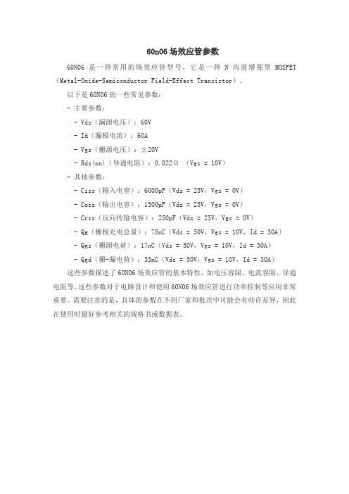
60n06场效应管参数
60N06是一种常用的场效应管型号,它是一种N沟道增强型MOSFET (Metal-Oxide-Semiconductor Field-Effect Transistor)。
以下是60N06的一些常见参数:
- 主要参数:
- Vds(漏源电压):60V
- Id(漏极电流):60A
- Vgs(栅源电压):±20V
- Rds(on)(导通电阻):0.022Ω(Vgs = 10V)
- 其他参数:
- Ciss(输入电容):6000pF(Vds = 25V,Vgs = 0V)
- Coss(输出电容):1500pF(Vds = 25V,Vgs = 0V)
- Crss(反向传输电容):250pF(Vds = 25V,Vgs = 0V)
- Qg(栅极充电总量):78nC(Vds = 50V,Vgs = 10V,Id = 30A)
- Qgs(栅源电荷):17nC(Vds = 50V,Vgs = 10V,Id = 30A)
- Qgd(栅-漏电荷):33nC(Vds = 50V,Vgs = 10V,Id = 30A)
这些参数描述了60N06场效应管的基本特性,如电压容限、电流容限、导通电阻等。
这些参数对于电路设计和使用60N06场效应管进行功率控制等应用非常重要。
需要注意的是,具体的参数在不同厂家和批次中可能会有些许差异,因此在使用时最好参考相关的规格书或数据表。
士兰微电子 SVF2N60RD M MJ 说明书

2A 、600V N 沟道增强型场效应管描述SVF2N60RD/M/MJ N 沟道增强型高压功率MOS 场效应晶体管采用士兰微电子的F-Cell TM 平面高压VDMOS 工艺技术制造。
先进的工艺及元胞结构使得该产品具有较低的导通电阻、优越的开关性能及很高的雪崩击穿耐量。
该产品可广泛应用于AC-DC 开关电源,DC-DC 电源转换器,高压H 桥PWM 马达驱动。
特点♦ 2A ,600V ,R DS(on)(典型值)=3.7 @V GS =10V ♦ 低栅极电荷量 ♦ 低反向传输电容 ♦ 开关速度快 ♦提升了dv/dt 能力命名规则士兰F-Cell 工艺VDMOS 产品标识额定电流标识,采用1-2位数字;例如:4代表 4A额定耐压值,采用2位数字例如:60表示600V封装外形标识例如:FJH:TO-220FJH;F:TO-220FS V F X N X X R X沟道极性标识,N 代表N 沟道版本产品规格分类极限参数(除非特殊说明,T C =25︒C)热阻特性电气参数(除非特殊说明,T C =25︒C)源-漏二极管特性参数注:1. L=30mH ,I AS =6.6A ,V DD =100V ,R G =25Ω,开始温度T J =25︒C;2. V DS =0~400V ,I SD <=12A , T J =25︒C;3. VDS =0~480V;4. 脉冲测试: 脉冲宽度≤300μs ,占空比≤2%;5.基本上不受工作温度的影响。
典型特性曲线图1. 输出特性图2.传输特性漏极电流 – I D (A )0.010.1100.1110100漏源电压 – V DS (V )漏极电流 – I D (A )0.01110024681013579栅源电压 – V GS (V )3.203.403.603.804.000 1.52 2.5漏源导通电阻 – R D S (o n )(Ω)漏极电流 – I D (A )图3. 导通电阻vs.漏极电流和栅极电压0.20.40.60.8 1.41.20.11100反向漏极电流 – I D R (A )源漏电压 – V SD (V )图4. 体二极管正向压降vs.漏极电流、温度4.201.010.110典型特性曲线(续)0.80.91.11.0-100-5050100200漏源击穿电压(标准化)– B V D S S结温 – T J (°C)图7. 击穿电压vs.温度特性漏源导通电阻(标准化) – R D S (o n )图8. 导通电阻vs.温度特性结温 – T J (°C)1.21502.0-100-50501002003.0150漏极电流 - I D (A )10-210-110010110101102103图9. 最大安全工作区域(SVF2N60RD/M/MJ)漏源电压- V DS (V)图5. 电容特性电容(p F )0.1110100漏源电压 – V DS (V )050150350250450100200400300图6. 电荷量特性栅源电压– V G S (V )0410总栅极电荷 – Q g (nC)246810128262550751001251500.51.01.52.0漏极电流 - I D (A )壳温– T C (°C)图 10. 最大漏电流vs. 壳温典型测试电路12VV DSV GS10V电荷量栅极电荷量测试电路及波形图开关时间测试电路及波形图V DSV GS10%90%E AS 测试电路及波形图V DDLBV DSS I ASV DD封装外形图封装外形图(续)声明:♦士兰保留说明书的更改权,恕不另行通知!客户在下单前应获取最新版本资料,并验证相关信息是否完整和最新。
Vishay:威世半导体新能源市场和应用

Trr 平衡图
Vf @ If=8A Vs Trr @ If=8A, di/dt=500A/µs, Vr=390V, Tj=25°C (soft mode)
80
Trr @ If=8A, di/dt=500A/µs, Vr=390V, Tj=25°C (ns)
70
ETL Series
60
DCM PFC
50
Package TO220
IF (A) 30 30
Vrrm (V) 600 600 600 600 600 600 600 600 600 600 600 600 1200
Vf (V) 1.4 1.15 1.4 1.15 1.4 1.15 1.4 1.15 1.4 1.15 1.1 1.2 1.4
trr (ns) 26 30 26 30 26 30 26 30 26 30 27 34 95
威世半导体新能源市场和应用
ht 导 tp 体 :/ 器 /b 件 bs 应 ic 用 .b 技 ig 术 -b 论 it 坛 .c om /
肖特基旁路二极管,快恢二极管,逆变IGBT模块,高 压MOSFET
半
威世市场部 2011年12月
Click to edit Master Title Style 威世半导体产品太阳能系统市场优势
半
超快恢复升压二极管
ht 导 tp 体 :/ 器 /b 件 bs 应 ic 用 .b 技 ig 术 -b 论 it 坛 .c om /
Fred Pt® 超快恢复二极管
半
Click to edit Master Title Style 超快恢复二极管太阳能逆变应用电路
Ultrafast diodes
D Series (400V, 500V, 600V)
双n沟道增强型功率mosfet

TC8 2 0 5 A TC8205A 双N 沟道增强型功率MOSFET1. 描述 引脚排列共漏极双N 沟道增强型功率场效应管具有快速开关、超低导通电阻和高性价比的特点。
适用于设计电池保护或低压开关的电路。
2. 特点z 低导通电阻 z 低驱动电流z 低栅极电压2.5V z V DS =20Vz I D =6A @ V GS =4.5V :R DS(ON)<26m Ω (Typ.22m Ω) @ V GS =4.5V3. 应用领域z 锂电池充电保护 z 电源管理z 便携式设备z 负载开关(顶视)4. 框图Shenzhen Century Tianchuang Technology Co.,Ltd.16. 最大额定参数参数符号值单位漏源电压V DS20 V 栅源电压V GS±10 V 漏极电流,V GS =4.5V,@T a=25°C I D 6 A 漏极电流,V GS =4.5V,@T a=70°C I D 4.8 A 漏极脉冲电流(注1)I DM20 A 功耗,@T a25°C P D 1.5 W 工作结温T j-55 ~ +150 °C存储温度T stg-55 ~ +150 °C功耗随温升的线性降低因数0.008W/°C热阻,结到环境(注2)R thj-a83 °C/W注1:脉冲宽度受最大结温限制注2:贴装在1平方英寸铜盘上,板材FR4;当贴装在最小铜盘上,208°C /W7. 电气特性(T j= 25°C,除非另有注明)参数符号测试条件最小值典型值最大值单位漏源击穿电压 BV DSS V GS = 0, I D = 250µA20 22 40 V漏源漏电流I DSS V DS= 20V, V GS = 0 - - 1 µA栅源漏电流I GSS V GS= ±10V,V DS= 0 - - ±100 nA击穿电压温度系数BV△DSS/T△j参考点25°CI D=1mA- 0.03 - V/°C栅极门限电压V GS(th)V DS= V GS, I D = 250µA 0.5 0.70 1.2 V2参数符号测试条件最小值典型值最大值单位漏源导通电阻(注1)R DS(ON)8205AV GS= 4.5VI D = 4.5A- 22 26mΩV GS= 2.5V- 26 32I D = 3.5A正向跨导g fs V DS= 5V, I D = 4.5A - 10 - S栅极总电荷(注1)Q g I D= 6AV DS= 10VV GS = 4.5V - 10 15nC栅源电荷Q gs- 2.3 - 栅漏电荷Q gd- 3 -导通延时(注1)T d(on)V DS= 10VI D= 1AV GS= 4.5VR G = 6Ω- 10 20ns上升时间T r- 11 25 关断延时T d(off)- 35 70 下降时间T f- 30 60输入电容C iss V GS= 0VV DS= 8Vf =1.0MHz - 600 -pF输出电容C oss- 330 - 反向传输电容C rss- 140 -源漏二极管正向导通电压(注1)V SDI S=1.7A, V GS=0VT j=25°C- 0.72 1.2 V漏源连续电流I S --1.7A注1:脉冲宽度≤300µs,占空比≤2% 38. 特性曲线图图1. 典型输出特性(T C=25°C)图2. 典型输出特性(T C=150°C)图3. R DS(ON)阻值与结温的关系图4. 导通电阻与结温的归一化关系图5. 反向二极管的正向特性图6. 栅极门限电压与结温的关系 4图7. 栅极电荷特性图8. 典型电容特性图9. 最大安全工作区域图10. 瞬态热阻图11. 开关时间波形图12. 栅极电荷波形 5 Shenzhen Century Tianchuang Technology Co.,Ltd.9. 封装尺寸TSSOP8符号尺寸(mm) 符号尺寸(mm) 最小值最大值最小值最大值A - 1.20 E1 4.30 4.50 A1 0.05 0.15 F 0.65 (典型值)B 0.19 0.30 L 0.45 0.75 D 2.90 3.10 L11.00 (典型值)E 6.40 (典型值)6SOT23-6符号尺寸(mm ) 符号尺寸(mm ) 最小值最大值最小值最大值A 1.450 B2 1.900 A1 0.900 0.130 C 0.127D 2.900 L 0.600 E1 2.800 L1 0.250E 1.600 R 0.100 B 0.300 0.500 R1 0.100 0.250 B1 0.9507。
DMN6140L 60V N-CHANNEL 增强模式 MOSFET 产品说明书

DMN6140L60V N-CHANNEL ENHANCEMENT MODE MOSFET Product SummaryDescriptionThis new generation MOSFET is designed to minimize the on-stateresistance (R DS(ON)) and yet maintain superior switching performance,making it ideal for high efficiency power management applications.Applications∙DC-DC Converters∙Power Management Functions∙Analog SwitchFeatures and Benefits∙Low On-Resistance∙Low Input Capacitance∙Fast Switching Speed∙Low Input/Output Leakage∙Totally Lead-Free & Fully RoHS Compliant (Notes 1 & 2)∙Halogen and Antimony Free. “Green” Device (Note 3)∙Qualified to AEC-Q101 Standards for High ReliabilityMechanical Data∙Case: SOT23∙Case Material: Molded Plastic, “Green” Molding Compound;UL Flammability Classification Rating 94V-0∙Moisture Sensitivity: Level 1 per J-STD-020∙Terminal Connections: See Diagram∙Terminals: Finish – Matte Tin Annealed over Copper Leadframe.Solderable per MIL-STD-202, Method 208∙Weight: 0.0072 grams (Approximate)Ordering Information(Note 4)Notes: 1. No purposely added lead. Fully EU Directive 2002/95/EC (RoHS) & 2011/65/EU (RoHS 2) compliant.2. See /quality/lead_free.html for more information about Diodes Incorporated’s definitions of Halogen- and Antimony-free, "Green"and Lead-free.3. Halogen- and Antimony-free "Green” products are defined as those which contain <900ppm bromine, <900ppm chlorine (<1500ppm total Br + Cl) and<1000ppm antimony compounds.4. For packaging details, go to our website at /products/packages.html.Marking InformationTop View Pin ConfigurationSOT23N61 = Marking CodeYM = Date Code MarkingY = Year (ex: Y = 2011)M = Month (ex: 9 = September)DGEquivalent CircuitN61YMe3Maximum Ratings (@T A = +25°C, unless otherwise specified.)Thermal Characteristics (@TA = +25°C, unless otherwise specified.)Notes: 5. Device mounted on FR-4 PC board, with minimum recommended pad layout, single sided.6. Device mounted on FR-4 substrate PC board, 2oz copper, with thermal vias to bottom layer 1in. square copper plate.10.0V , DRAIN-SOURCE VOLTAGE (V)Figure 1 Typical Output CharacteristicDS I , D R A I N C U R R E N T (A )D2468V , GATE-SOURCE VOLTAGE (V)Figure 2 Typical Transfer Characteristics GS I , D R A I N C U R R E N T (A )DI , DRAIN-SOURCE CURRENT (A)D Figure 3 Typical On-Resistance vs.Drain Current and Gate VoltageR , D R A I N -S O U R C E O N -R E S I S T A N C E ()D S (ON )Ω00.10.20.30.40.52345678910V , GATE-SOURCE VOLTAGE (V)Figure 4 Typical Drain-Source On Resistancevs. Gate-Source Voltage GS R , D R A I N -S O U R C E O N -R E S I S T A N C E ()D S (O N )Ω00.040.080.120.160.20.240.280.320.360.4I , DRAIN CURRENT (A)Figure 5 Typical On-Resistance vs.Drain Current and T emperatureD R , D R A I N -S O U R CE O N -R E S I S T A N C E ()D S (O N )Ω-50-250255075100125150T , JUNCTION TEMPERATURE (C)Figure 6 On-Resistance Variation with Temperature J ︒R , D R A I N -S O U R C EO N -R E S I S T A N C E (N O R M A L I Z E D )D S (O N )0.3TJ, JUNCTION TEMPERATURE (C)Figure 7 On-Resistance Variation with Temperature ︒R , D R A I N -S O U R C E O N -R E S I S T A N C E ()D S (O N )ΩV , G A T E T H R E S H O L D V O L T A G E (V )G S (t h)V , SOURCE-DRAIN VOLTAGE (V)Figure 9 Diode Forward Voltage vs. Current SD 012345678910I , S O U R C E C U R R E N T (A )S 101000V , DRAIN-SOURCE VOLTAGE (V)Figure 10 Typical Junction CapacitanceDS C , J U N C T I O NC A P A C I T A N C E (p F )T Q , TOTAL GATE CHARGE (nC)Figure 11 Gate Chargeg V G A T E T H R E S H O L D V O LT A G E (V )G S 0.0010.010.11100V , DRAIN-SOURCE VOLTAGE (V)Figure 12 SOA, Safe Operation AreaDS I , D R A I N C U R R E N T (A )DPackage Outline DimensionsPlease see AP02002 at /datasheets/ap02002.pdf for the latest version.Suggested Pad LayoutPlease see AP02001 at /datasheets/ap02001.pdf for the latest version.0.11t1, PULSE DURATION TIME (sec)Figure 13 Transient Thermal Resistancer (t ), T R A N S I E N T T H E R M A L R E S I S T A N C EX E YC Z All 7°。
STF18N60M2 TO-220FP 封装 N-沟道 600 V,0.255 Ω (典型值),13
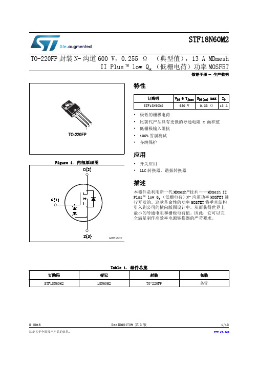
这是关于全面投产产品的信息。
8 2013DocID024729 第2版1/12STF18N60M2TO-220FP 封装N-沟道600 V,0.255 Ω (典型值),13 A MDmeshII Plus ™ low Q g (低栅电荷)功率MOSFET数据手册生产数据特性•极低的栅极电荷•比前代产品具有更低的导通电阻 x 面积值•低栅极输入阻抗•100%雪崩测试•齐纳保护应用•开关应用•LLC 转换器,谐振转换器描述本器件是利用新一代MDmesh ™技术——MDmesh II Plus ™ low Q g (低栅电荷)N-沟道功率MOSFET 进行开发的。
这款革命性的功率MOSFET 将垂直结构引入到公司的横向版图设计中,从而获得世界上最小的导通电阻和栅极电荷值。
因此,它可以完全满足制作高效率电源转换器的严苛要求。
订购码V DS @ T Jmax R DS(on) max I D STF18N60M2650 V0.28 Ω13 ATable 1. 器件总览订购码标记封装包装STF18N60M218N60M2TO-220FP条管目录STF18N60M2目录1电气额定值 . . . . . . . . . . . . . . . . . . . . . . . . . . . 32电气特性 . . . . . . . . . . . . . . . . . . . . . . . . . . . . 42.1电气特性(曲线) . . . . . . . . . . . . . . . . . . . . . . . .6 3测试电路 . . . . . . . . . . . . . . . . . . . . . . . . . . 8 4封装机械数据 . . . . . . . . . . . . . . . . . . . . . . . . . . 9 5修订历史 . . . . . . . . . . . . . . . . . . . . . . . . . . . .112/12DocID024729 第2版DocID024729 第2版3/12STF18N60M2电气额定值1 电气额定值Table 2. 绝对最大额定值符号参数数值单位V GS 栅-源电压± 25V I D 漏极电流(连续)@ T C = 25 °C 13(1)1.受限于封装A I D 漏极电流(连续)@ T C = 100 °C 8(1)A I DM (2)2.脉冲宽度受限于安全工作区漏极电流(脉冲)52(1)A P TOT总损耗@ T C = 25 °C25W dv/dt (3)3.I SD £ 13 A,di/dt £ 400 A/µs ;V DS peak < V (BR)DSS , V DD =400 V.峰值二极管恢复电压斜坡15V/ns dv/dt (4)4.V DS £ 480 VMOSFET 抗dv/dt 瞬变能力50V/ns V ISO 所有三个引脚到外部散热器(t = 1 s ;T C = 25℃)的绝缘耐压(均方根值)2500V T stg 存储温度- 55 至 150°CT j最大值 工作结温Table 3. 热学数据符号参数数值单位R thj-case 结到外壳最大热阻 3.6°C/W R thj-amb结到环境最大热阻62.5°C/WTable 4. 雪崩特性符号参数数值单位I AR 雪崩电流,重复或非重复(脉冲宽度受限于T jmax )3A E AS单脉冲雪崩能量值(起始T j =25°C, I D = I AR ;V DD =50)135mJ电气特性STF18N60M24/12DocID024729 第2版2 电气特性(T C = 25 °C,除非另有规定)Table 5. 导通/关断状态符号参数测试条件最小值典型值最大值单位V (BR)DSS 漏-源击穿电压 I D = 1 mA,V GS = 0600V I DSS 零栅极电压漏极电流(V GS = 0)V DS = 600 V1µA V DS = 600 V,T C =125 °C 100µA I GSS 栅体泄漏电流(V DS = 0)V GS = ± 25 V±10µA V GS(th)栅极阈值电压V DS = V GS ,I D = 250 µA 234V R DS(on)静态漏-源 导通电阻V GS = 10 V,I D = 6.5 A0.2550.28WTable 6. 动态符号参数测试条件最小值典型值最大值单位C iss 输入电容V DS = 100 V,f = 1 MHz,V GS = 0-791-pF C oss 输出电容-40-pF C rss反向传输电容- 5.6-pF C oss eq.(1)1.C oss eq.定义为当V DS 从0升到80% V DSS 时,可与C oss 提供相同充电时间的恒定等效电容。
维沙伊·西林奇60伏特P通道MOSFET产品说明书

Vishay SiliconixSi7309DNDocument Number: P-Channel 60-V (D-S) MOSFETFEATURES•Halogen-free According to IEC 61249-2-21Available•TrenchFET ® Power MOSFET•Low Thermal Resistance PowerPAK ® Packagewith Small Size and Low 1.07 mm ProfileAPPLICATIONS•CCFL inverter •Class D-ampPRODUCT SUMMARYV DS (V)R DS(on) (Ω)I D (A)a Q g (Typ.)- 600.115 at VGS = - 10 V - 814.5 nC0.146 at V GS = - 4.5 V- 8Notes:a.Package limited.b.Surface Mounted on 1" x 1" FR4 board.c. t = 10 s.d.See Solder Profile (/ppg?73257). The PowerPAK 1212-8 is a leadless package. The end of the lead terminal is exposed copper (not plated) as a result of the singulation process in manufacturing. A solder fillet at the exposed copper tip cannot be guaranteed and is not required to ensure adequate bottom side solder interconnection.e.Rework Conditions: manual soldering with a soldering iron is not recommended for leadless components.f.Maximum under Steady State conditions is 81 °C/W. ABSOLUTE MAXIMUM RATINGS T A = 25 °C, unless otherwise notedParameter Symbol Limit UnitDrain-Source VoltageV DS - 60VGate-Source VoltageV GS ± 20Continuous Drain Current (T J = 150 °C)T C = 25 °C I D - 8a AT C = 70 °C - 7.8T A = 25 °C - 3.9b, c T A = 70 °C - 3.1b, cPulsed Drain Current (10 µs Width)I DM - 20Continuous Source-Drain Diode CurrentT C = 25 °C I S - 8aT A = 25 °C - 2.7b, cAvalanche CurrentL = 0.1 mHI AS - 15Single-Pulse Avalanche EnergyE AS 11mJ Maximum Power Dissipation T C = 25 °C P D 19.8WT C = 70 °C 12.7T A = 25 °C 3.2b, c T A = 70 °C 2.1b, cOperating Junction and Storage T emperature RangeT J , T stg - 55 to 150°C THERMAL RESISTANCE RATINGSParameter Symbol Typical Maximum UnitMaximum Junction-to-Ambienta, d R thJA 3139°C/WMaximum Junction-to-Case (Drain)Steady State R thJC 5 6.3 Document Number: 73434Vishay SiliconixSi7309DNNotes:a. Pulse test; pulse width ≤ 300 µs, duty cycle ≤ 2 %.b. Guaranteed by design, not subject to production testing.Stresses beyond those listed under “Absolute Maximum Ratings” may cause permanent damage to the device. These are stress ratings only, and functional operation of the device at these or any other conditions beyond those indicated in the operational sections of the specifications is not implied. Exposure to absolute maximum rating conditions for extended periods may affect device reliability.SPECIFICATIONS T J = 25 °C, unless otherwise notedParameter Symbol Test Conditions Min.Typ.Max.UnitStaticDrain-Source Breakdown Voltage V DS V GS = 0 V, I D = - 250 µA- 60V V DS Temperature Coefficient ΔV DS /T J I D = - 250 µA - 50mV/°C V GS(th) Temperature Coefficient ΔV GS(th)/T J + 3.8Gate-Source Threshold Voltage V GS(th) V DS = V GS , I D = - 250 µA - 1- 3V Gate-Source LeakageI GSS V DS = 0 V , V GS = ± 20 V ± 100ns Zero Gate Voltage Drain Current I DSS V DS = - 60 V , V GS = 0 V - 1µA V DS = - 60 V, V GS = 0 V, T J = 85 °C- 10On-State Drain Current aI D(on) V DS ≥ - 5 V , V GS = - 10 V - 20A Drain-Source On-State Resistance a R DS(on) V GS = - 10 V, I D = - 3.9 A 0.0920.115ΩV GS = - 4.5 V , I D = - 3.5 A 0.1200.146Forward T ransconductance a g fsV DS = - 15 V , I D = - 3.9 A10SDynamic bInput Capacitance C iss V DS = - 30 V , V GS = 0 V , f = 1 MHz600pFOutput CapacitanceC oss 70Reverse Transfer Capacitance C rss 50Total Gate Charge Q g V DS = - 30 V , V GS = - 10 V , ID = - 3.9 A 14.522nC V DS = - 30 V , V GS = - 4.5 V, I D = - 3.9 A 7.512Gate-Source Charge Q gs 2.2Gate-Drain Charge Q gd 3.7Gate Resistance R g f = 1 MHz14ΩTurn-On Delay Time t d(on) V DD = - 30 V, R L = 9.4 ΩI D ≅ - 3.2 A, V GEN = - 4.5 V , R g = 1 Ω2540ns Rise Timet r 80120Turn-Off Delay Time t d(off) 3350Fall Timet f 3550Turn-On Delay Time t d(on) V DD = - 30 V, R L = 9.4 ΩI D ≅ - 3.2 A, V GEN = - 10 V , R g = 1 Ω1015Rise Timet r 1525Turn-Off Delay Time t d(off) 3045Fall Timet f3350Drain-Source Body Diode Characteristics Continuous Source-Drain Diode Current I S T C = 25 °C- 8A Pulse Diode Forward Current I SM - 20Body Diode VoltageV SD I S = - 1.3 A, V GS = 0 V- 0.8- 1.2V Body Diode Reverse Recovery Time t rr I F = - 1.3 A, dI/dt = - 100 A/µs, T J = 25 °C3050ns Body Diode Reverse Recovery Charge Q rr 3250nC Reverse Recovery Fall Time t a 17nsReverse Recovery Rise Timet b13Document Number: Document Number: 73434Document Number: Vishay SiliconixSi7309DNTYPICAL CHARACTERISTICS 25°C, unless otherwise noted* The power dissipation P D is based on T J(max) = 150 °C, using junction-to-case thermal resistance, and is more useful in settling the upper dissipation limit for cases where additional heatsinking is used. It is used to determine the current rating, when this rating falls below the package limit.Current Derating*Power DeratingSingle Pulse Avalanche Capability Document Number: 73434Vishay SiliconixSi7309DNTYPICAL CHARACTERISTICS 25°C, unless otherwise notedVishay Siliconix maintains worldwide manufacturing capability. Products may be manufactured at one of several qualified locations. Reliability data for Silicon Technology and Package Reliability represent a composite of all qualified locations. For related documents such as package/tape drawings, part marking, and reliability data, see /ppg?73434.Normalized Thermal Transient Impedance, Junction-to-CaseRevison: 09-Jan-171Document Number: 71656Vishay SiliconixAN822Document Number PowerPAK ® 1212 Mounting and Thermal ConsiderationsJohnson ZhaoMOSFETs for switching applications are now available with die on resistances around 1 m Ω and with the capability to handle 85 A. While these die capabilities represent a major advance over what was available just a few years ago, it is important for power MOSFET packaging technology to keep pace. It should be obvi-ous that degradation of a high performance die by the package is undesirable. PowerPAK is a new package technology that addresses these issues. The PowerPAK 1212-8 provides ultra-low thermal impedance in a small package that is ideal for space-constrained applications. In this application note, the PowerPAK 1212-8’s construction is described. Following this,mounting information is presented. Finally, thermal and electrical performance is discussed.THE PowerPAK PACKAGEThe PowerPAK 1212-8 package (Figure 1) is a deriva-tive of PowerPAK SO-8. It utilizes the same packaging technology, maximizing the die area. The bottom of the die attach pad is exposed to provide a direct, low resis-tance thermal path to the substrate the device is mounted on. The PowerPAK 1212-8 thus translates the benefits of the PowerPAK SO-8 into a smaller package, with the same level of thermal performance.(Please refer to application note “PowerPAK SO-8Mounting and Thermal Considerations.”)The PowerPAK 1212-8 has a footprint area compara-ble to TSOP-6. It is over 40 % smaller than standard TSSOP-8. Its die capacity is more than twice the size of the standard TSOP-6’s. It has thermal performance an order of magnitude better than the SO-8, and 20times better than TSSOP-8. Its thermal performance is better than all current SMT packages in the market. It will take the advantage of any PC board heat sink capability. Bringing the junction temperature down also increases the die efficiency by around 20 % compared with TSSOP-8. For applications where bigger pack-ages are typically required solely for thermal consider-ation, the PowerPAK 1212-8 is a good option.Both the single and dual PowerPAK 1212-8 utilize the same pin-outs as the single and dual PowerPAK SO-8.The low 1.05 mm PowerPAK height profile makes both versions an excellent choice for applications with space constraints.PowerPAK 1212 SINGLE MOUNTINGTo take the advantage of the single PowerPAK 1212-8’s thermal performance see Application Note 826,Recommended Minimum Pad Patterns With Outline Drawing Access for Vishay Siliconix MOSFETs. Click on the PowerPAK 1212-8 single in the index of this document.In this figure, the drain land pattern is given to make full contact to the drain pad on the PowerPAK package.This land pattern can be extended to the left, right, and top of the drawn pattern. This extension will serve to increase the heat dissipation by decreasing the ther-mal resistance from the foot of the PowerPAK to the PC board and therefore to the ambient. Note that increasing the drain land area beyond a certain point will yield little decrease in foot-to-board and foot-to-ambient thermal resistance. Under specific conditions of board configuration, copper weight, and layer stack,experiments have found that adding copper beyond an area of about 0.3 to 0.5 in 2 of will yield little improve-ment in thermal performance.Figure 1.PowerPAK 1212 Devices Document Number 71681Vishay SiliconixAN822PowerPAK 1212 DUALTo take the advantage of the dual PowerPAK 1212-8’s thermal performance, the minimum recommended land pattern can be found in Application Note 826,Recommended Minimum Pad Patterns With Outline Drawing Access for Vishay Siliconix MOSFETs . Click on the PowerPAK 1212-8 dual in the index of this doc-ument.The gap between the two drain pads is 10 mils. This matches the spacing of the two drain pads on the Pow-erPAK 1212-8 dual package.This land pattern can be extended to the left, right, and top of the drawn pattern. This extension will serve to increase the heat dissipation by decreasing the ther-mal resistance from the foot of the PowerPAK to the PC board and therefore to the ambient. Note that increasing the drain land area beyond a certain point will yield little decrease in foot-to-board and foot-to-ambient thermal resistance. Under specific conditions of board configuration, copper weight, and layer stack,experiments have found that adding copper beyond an area of about 0.3 to 0.5 in 2 of will yield little improve-ment in thermal performance.REFLOW SOLDERINGVishay Siliconix surface-mount packages meet solder reflow reliability requirements. Devices are subjected to solder reflow as a preconditioning test and are then reliability-tested using temperature cycle, bias humid-ity, HAST, or pressure pot. The solder reflow tempera-ture profile used, and the temperatures and time duration, are shown in Figures 2 and 3. For the lead (Pb)-free solder profile, see /doc?73257.Ramp-Up Rate+ 6°C /Second Maximum Temperature at 155 ± 15 °C 120 Seconds Maximum Temperature Above 180 °C 70 - 180 Seconds Maximum T emperature240 + 5/- 0 °CTime at Maximum T emperature 20 - 40 Seconds Ramp-Down Rate+ 6 °C/Second MaximumFigure 2. Solder Reflow Temperature ProfileFigure 3.Solder Reflow Temperatures and Time DurationsVishay SiliconixAN822Document Number THERMAL PERFORMANCE IntroductionA basic measure of a device’s thermal performance is the junction-to-case thermal resistance, R θjc, or the junction to- foot thermal resistance, R θjf. This parameter is measured for the device mounted to an infinite heat sink and is therefore a characterization of the device only, in other words, independent of the properties of the object to which the device is mounted. Table 1 shows a comparison of the PowerPAK 1212-8, PowerPAK SO-8,standard TSSOP-8 and SO-8 equivalent steady state performance.By minimizing the junction-to-foot thermal resistance, the MOSFET die temperature is very close to the tempera-ture of the PC board. Consider four devices mounted on a PC board with a board temperature of 45 °C (Figure 4). Suppose each device is dissipating 2 W. Using the junc-tion-to-foot thermal resistance characteristics of the PowerPAK 1212-8 and the other SMT packages, die temperatures are determined to be 49.8 °C for the Pow-erPAK 1212-8, 85 °C for the standard SO-8, 149 °C for standard TSSOP-8, and 125 °C for TSOP-6. This is a 4.8 °C rise above the board temperature for the Power-PAK 1212-8, and over 40 °C for other SMT packages. A 4.8 °C rise has minimal effect on r DS(ON) whereas a rise of over 40 °C will cause an increase in r DS(ON) as high as 20 %.Spreading CopperDesigners add additional copper, spreading copper, to the drain pad to aid in conducting heat from a device. It is helpful to have some information about the thermal performance for a given area of spreading copper.Figure 5 and Figure 6 show the thermal resistance of a PowerPAK 1212-8 single and dual devices mounted on a 2-in. x 2-in., four-layer FR-4 PC boards. The two inter-nal layers and the backside layer are solid copper. The internal layers were chosen as solid copper to model the large power and ground planes common in many appli-cations. The top layer was cut back to a smaller area and at each step junction-to-ambient thermal resistance measurements were taken. The results indicate that an area above 0.2 to 0.3 square inches of spreading copper gives no additional thermal performance improvement.A subsequent experiment was run where the copper on the back-side was reduced, first to 50 % in stripes to mimic circuit traces, and then totally removed. No signif-icant effect was observed.TABLE 1: EQIVALENT STEADY STATE PERFORMANCEPackage SO-8TSSOP-8TSOP-8PPAK 1212PPAK SO-8ConfigurationSingleDual Single Dual Single Dual Single Dual Single Dual Thermal Resiatance R thJC (C/W)2040528340902.45.51.85.5Figure 4. Temperature of Devices on a PC Board 4Document Number 7168103-Mar-06Vishay SiliconixAN822CONCLUSIONSAs a derivative of the PowerPAK SO-8, the PowerPAK 1212-8 uses the same packaging technology and has been shown to have the same level of thermal perfor-mance while having a footprint that is more than 40 %smaller than the standard TSSOP-8.Recommended PowerPAK 1212-8 land patterns are provided to aid in PC board layout for designs using this new package.The PowerPAK 1212-8 combines small size with attrac-tive thermal characteristics. By minimizing the thermal rise above the board temperature, PowerPAK simplifies thermal design considerations, allows the device to run cooler, keeps r DS(ON) low, and permits the device to handle more current than a same- or larger-size MOS-FET die in the standard TSSOP-8 or SO-8 packages.Figure 5. Spreading Copper - Si7401DNFigure 6. Spreading Copper - Junction-to-Ambient PerformanceApplication Note 826Vishay SiliconixDocument Number: Revision: 21-Jan-087A P P L I C A T I O NN O T ERECOMMENDED MINIMUM PADS FOR PowerPAK® 1212-8 SingleLegal Disclaimer Notice VishayDisclaimerALL PRODUCT, PRODUCT SPECIFICAT IONS AND DAT A ARE SUBJECT T O CHANGE WIT HOUT NOT ICE T O IMPROVE RELIABILITY, FUNCTION OR DESIGN OR OTHERWISE.Vishay Intertechnology, Inc., its affiliates, agents, and employees, and all persons acting on its or their behalf (collectively, “Vishay”), disclaim any and all liability for any errors, inaccuracies or incompleteness contained in any datasheet or in any other disclosure relating to any product.Vishay makes no warranty, representation or guarantee regarding the suitability of the products for any particular purpose or the continuing production of any product. To the maximum extent permitted by applicable law, Vishay disclaims (i) any and all liability arising out of the application or use of any product, (ii) any and all liability, including without limitation special, consequential or incidental damages, and (iii) any and all implied warranties, including warranties of fitness for particular purpose, non-infringement and merchantability.Statements regarding the suitability of products for certain types of applications are based on Vishay’s knowledge of typical requirements that are often placed on Vishay products in generic applications. Such statements are not binding statements about the suitability of products for a particular application. It is the customer’s responsibility to validate that a particular product with the properties described in the product specification is suitable for use in a particular application. Parameters provided in datasheets and / or specifications may vary in different applications and performance may vary over time. All operating parameters, including typical parameters, must be validated for each customer application by the customer’s technical experts. Product specifications do not expand or otherwise modify Vishay’s terms and conditions of purchase, including but not limited to the warranty expressed therein.Except as expressly indicated in writing, Vishay products are not designed for use in medical, life-saving, or life-sustaining applications or for any other application in which the failure of the Vishay product could result in personal injury or death. Customers using or selling Vishay products not expressly indicated for use in such applications do so at their own risk. Please contact authorized Vishay personnel to obtain written terms and conditions regarding products designed for such applications.No license, express or implied, by estoppel or otherwise, to any intellectual property rights is granted by this document or by any conduct of Vishay. Product names and markings noted herein may be trademarks of their respective owners.© 2017 VISHAY INTERTECHNOLOGY, INC. ALL RIGHTS RESERVEDRevision: 08-Feb-171Document Number: 91000。
Vishay Siliconix推出新型500V N沟道功率MOSFET

V , , 2 5 , o r ur r 0 7 n4 P — 1 F ut Q at 0 7 4 h e2
[0 B r ziD v e N Csnh s o r utm zd 1 】 e oz a i , o tei f wf s i t , d y s l o c o e
d man s e i c mu pr c s o y t ms o —c i .I o i p cf hi o e s rs se — n h p EEE i Tr ns c in n Pa al l n srbu e y t ms v 1 , a a t so r le d Diti td S se , o a 6
线 电系统 。 四
【] e r ui n ue D m nq e ” o lt 7 D l me l nadHozt o iiu . A cmpe o J e e
4 rdo o G a i c mmu c t n a p i ain ma p n nt nia i p lc to p i g o o a 2D o me h No a c ie t r . 4 h I tr a in l I s C r h tc u e” t n e n to a EEE No h t r -Ea t W o k h p o Cic t a d S se , s rso n r uis n y tms NEW CAS 2 06 一 Co e e c o e d n s P 93 96 0 f n r n e Pr c e i g , - ,
n 2, 3 2 Fe r a y 2 05 P 1 -1 9, b u r 0 . 1
Vishay推出适用于移动设备和消费电子的30V MOSFET

实验研究够建立清晰的立体模型,满足数字线划图测绘的需求。
■ 2.4图根点及像控点测霣(1)图根控制点的选布本区图根控制点的选点严格按照实施方案要求执行,在 36km2范围内按每平方公里4个的密度要求,均匀布设,全区共布设图根控制点144个。
(2)像片控制点的选布因本区航摄重叠度大,内业模型连接容易,故像控布点 不考虑航摄分区,全区统_按横向、纵向间隔500m左右 均匀布设。
全区共布设像片控制点224个。
(3)图根点及像控点测量本区图根点及像控点的平面坐标和高程采用GPS-RTK 技术获得。
因图根点和像控点精度要求一致,故测量时采用 同一种作业模式、同步施测。
外业施测前,先利用D级控制网平差时求得控制点的 WGS84坐标与CGCS2000坐标两套成果,计算出WGS84 坐标与CGCS2000坐标之间的转换七参数,作为本次图根 点及像控点测量的转换参数。
外业施测时,基准站架设在本期施测的D级GPS控制 点上,并正确设置基准站的坐标系、转换参数、已知点坐标 和电台工作参数等;流动站也设置了坐标系、转换参数等。
外业测量时,流动站离开基准站的距离始终不大于10km。
在_个连续的测量时间段中,均对首尾的测量成果进行了检 验,方法是在已知点上进行初始化,测量两次,两次测量 之间重新进行初始化,取平均值做为最终测量成果,相邻基 准站间均联测1〜2公共点进行检核。
同时为了确保测量 成果的可靠性,外业观测时,对部分D级点进行了复测。
如D001点,已知成果正常水准高度为1709.385米,GPS-RTK检测成果高度为1709.376米,较差为9毫米;D009点,已知成果正常水准高度为1635.643米,GPS-RTK检测成 果高度为1635.655米,较差为-14毫米;较差结果数据表明,本次图根点、像控点测量精度良好,满足实施方案要求。
■ 2.5像片调绘本区属于荒漠无人区,地物稀少,调绘采用像片调绘的 方式实施。
考虑时间紧急,本区像片调绘采用上期制作的影 像图放大成1:2000进行调绘。
Vishay大幅扩充E系列650V N沟道功率MOSFET家族

Vishay大幅扩充E系列650V N沟道功率MOSFET
家族
新的E系列器件采用Vishay Siliconix超级结技术,导通电阻低至30m、电流达6A~105A,在8种封装中实现低FOM和高功率密度
宾夕法尼亚、MALVERN 2013 年 6 月4 日日前,Vishay Intertechnology,Inc.(NYSE 股市代号:VSH)宣布,其E系列器件新增650V功率MOSFET。
这些22款新器件采用8种不同封装,将10V下的导通电阻扩展到30mΩ~600mΩ,将最高电流等级扩大为6A~
105A。
650V E系列MOSFET基于下一代Vishay Siliconix超级结技术,针对可再生能源、工业、照明、电信、消费和计算市场中对输入电压安全裕量有额外要求的应用,Vishay Siliconix拓展了器件的峰值性能指标。
今天推出的器件使E系列的器件总数达到26个。
所有E系列器件都具有超低的导通电阻和栅极电荷,可实现极低的传导和开关损耗,可在功率因数校正、服务器和通信电源系统、焊接、不间断电源(UPS)、电池充电器、LED照明、半导体制造设备、适配器和太阳能逆变器等高功率、高性能开关电源中节省能源。
器件针对雪崩和通信模式中承受高能脉冲而设计,通过100%的UIS。
Vishay发布其E系列器件的首颗500V高压MOSFET
Vishay发布其E系列器件的首颗500V高压MOSFET日前,Vishay Intertechnology, Inc.(NYSE 股市代号:VSH)宣布,推出新的500V家族里首款MOSFET--- SiHx25N50E,该器件具有与该公司600V和650V E系列器件相同的低导通电阻和低开关损耗优点。
新器件的低导通电阻和栅极电荷在高功率、高性能的消费类产品、照明应用和ATX/桌面PC机开关电源(SMPS)里将起到节能的重要作用。
Vishay Siliconix SiHx25N50E 500 V MOSFET使用第二代超级结技术,为采用高性能平面技术的Vishay现有500V D系列器件补充了高效率产品。
这些25A器件的导通电阻为145mΩ ,提供TO-220 (SiHP25N50E)、TO-247AC (SiHG25N50E)和细引线的TO-220 FULLPAK (SiHA25N50E)等多种封装选项,这些低外形封装适用于薄型消费类产品。
新的MOSFET具有57nC的超低栅极电荷,栅极电荷与到导通电阻乘积也较低,该参数是功率转换应用里MOSFET的优值系数(FOM)。
与Vishay的600V和650V E系列器件类似,500V技术具有低导通电阻和优化的开关速度,能够提高功率因数校正(PFC)、双开关正激转换器和反激转换器应用里的效率和功率密度,器件符合RoHS,可承受雪崩和开关模式里的高能脉冲,保证极限值通过100% UIS测试。
器件规格表:器件ID (A) @25 °CRDS(on) (mΩ)@ 10 V(最大值)QG (nC)@ 10 V(典型值)封装SiHG25N50E2514557TO-247ACSiHP25N50E2514557TO-220SiHA25N50E2514557细引线TO-220 FULLPAK。
Vishay推出新款CMOS模拟开关和多路复用器
Vishay推出新款CMOS模拟开关和多路复用器
佚名
【期刊名称】《《电源技术应用》》
【年(卷),期】2011(35)11
【摘要】日前,Vishaylntertechnology,lnc.宣布,推出4款可使用27~16V 单电源或4-27.±8V双电源工作的新器件,充实其DG92xx系列CMOS模拟开关和多路复用器。
新器件具有工作电压范围宽、小封装尺寸和兼容低电压逻辑的特点,可用于高速、高精度开关应用。
【总页数】1页(P77-77)
【正文语种】中文
【中图分类】TM564
【相关文献】
1.Vishay Siliconix推出尺寸极小的新款低压模拟开关 [J],
2.Vishay推出新款CMOS模拟开关和多路复用器 [J], 无
3.Vishay推出尺寸极小的新款低压模拟开关 [J],
4.VISHAY推出三款高精度低压单片CMOS模拟开关 [J],
5.Vishay Siliconix推出新款模拟开关 [J],
因版权原因,仅展示原文概要,查看原文内容请购买。
泰克推出首个多千兆位汽车以太网一致性测试解决方案
行业视点佳的品质因数Rsp(Rdson*area)o NVBG015N065SC1, NTBG015N065SC1.NVH4L015N065SC1和NTH4L015N0 65SC1采用D2PAK7L和To247封装,具有市场最低的Rdson(12mOhm)。
这技术还优化能量损失品质因数,从而优化了汽车和工业应用中的性能。
内置门极电阻(Rg)为设计人员提供更大的灵活性,而无需使用外部门极电阻人为地降低器件的速度。
更高的浪涌、雪崩能力和短路鲁棒性都有助于增强耐用性,从而提供更高的可靠性和更长的器件使用寿命。
安森美半导体先进电源分部高级副总裁Asif Jak-wani在发布新品时说:"在现代电源应用中,如电动汽车(EV)车载充电器(OBC)和可再生能源、企业计算及电信等其他应用,高能效、可靠性和功率密度是设计人员一直面临的挑战。
这些新的SiC MOSFET比同等的硅开关技术显著提高性能,使工程师能够满足这些具有挑战性的设计目标。
增强的性能降低损耗,从而提高能效,减少热管理需求,并降低电磁干扰(EMI)。
使用这些新的SiC MOSFET的最终结果是更小、更轻、更高效和更可靠的电源方案新器件均为表面贴装,并提供行业标准封装类型,包括TO247和D2PAKo泰克推出首个多千兆位汽车以太网一致性测试解决方案泰克日前宣布推出TekExpress TM多千兆位汽车以太网一致性测试解决方案,这是满足复杂汽车设计要求的首个市场解决方案。
随着自动驾驶、5G和互联汽车解决方案等新的汽车技术的发展,必须测试承载支持这些技术所需的大量数据的路径,以确保汽车各子系统之间可靠的数据传输。
作为一种自动一致性测试应用,泰克TekExpress多千兆位汽车以太网一致性测试解决方案可以快速、准确、可靠地验证和调试多千兆位以太网芯片组和电子控制单元(ECUs),满足高达10Gb/s的物理媒体连接(PMA)发射机测量要求。
全自动一致性测试解决方案完全符合当前最新版IEEE802.3ch MultiGBASE -T1规范。
n勾道mos管
n勾道mos管随着科技的不断发展,电子产品的更新换代也越来越快,各种新型芯片和元器件层出不穷。
其中,n勾道mos管作为一种常用的场效应管,被广泛应用于电子领域中。
本文将对n勾道mos管的原理、特点、应用以及未来发展进行探讨。
一、n勾道mos管的原理n勾道mos管是一种场效应管,由金属氧化物半导体场效应管(MOSFET)演变而来。
它由n型沟道和p型衬底组成,沟道两侧分别嵌入了n型源极和漏极,同时在沟道下面覆盖一层绝缘氧化物层。
当外加正向电压时,沟道中的自由电子会受到电场力的作用,从源极流向漏极,形成电流;当外加反向电压时,沟道中的自由电子会受到绝缘氧化物层的屏蔽,无法流动,电流为零。
因此,n勾道mos管可以实现高速开关和电流控制的功能。
二、n勾道mos管的特点1.低开关损耗n勾道mos管的沟道电阻很小,因此在开关过程中的电阻损耗也很小,能够实现低开关损耗的效果。
这对于高频开关电路来说尤为重要,可以有效提高电路的转换效率。
2.高输入阻抗n勾道mos管的输入阻抗很大,可以减小外部电路对它的影响,同时也可以减小自身的功耗。
这一特点使得n勾道mos管适用于高精度放大器、滤波器等电路中。
3.可靠性高n勾道mos管的结构简单,制造工艺成熟,可以实现高可靠性的效果。
同时,它的工作温度范围广,能够适应各种环境。
三、n勾道mos管的应用1.高频功率放大器n勾道mos管的高频特性优良,能够实现高效率、高可靠性的功率放大。
它被广泛应用于无线通信、雷达、卫星通信等领域。
2.电源开关n勾道mos管的低开关损耗和高输入阻抗,使得它成为电源开关电路中的理想选择。
它可以实现高效率、高精度的电源管理,适用于电子产品中的电池管理、充电管理等领域。
3.驱动器n勾道mos管的高速开关特性,使得它成为各种驱动器电路中的理想选择。
它可以实现高速驱动,适用于电机驱动、LED驱动等领域。
四、n勾道mos管的未来发展随着电子产品的不断更新换代,对于元器件的要求也越来越高。
士兰微电子 3VD235600YL 高压MOSFET芯片 说明书
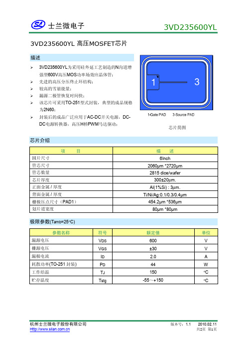
3VD235600YL高压MOSFET芯片描述Ø3VD235600YL为采用硅外延工艺制造的N沟道增强型600V高压MOS功率场效应晶体管;Ø先进的高压分压终止环结构;Ø较高的雪崩能量;Ø漏源二极管恢复时间快;Ø该芯片可采用TO-251型式封装,典型的成品规格为2N60;Ø封装后的成品广泛应用于AC-DC开关电源,DC-DC电源转换器,高压H桥PWM马达驱动;芯片简图芯片介绍项目描述圆片尺寸6Inch管芯尺寸2060μm *2720μm管芯数量2815 dice/wafer芯片厚度300±20µm.正面金属 /厚度Al(1%Si) : 3µm.背面金属 /厚度Ti/Ni/Ag:0.1/0.3/0.4μm栅极压点尺寸(PAD1)454.2μm *536μm划片道宽度80μm *80μm极限参数(T amb=25°C)参数名称符号额定值单位漏源电压V DS600V 栅源电压V GS±30V 漏极电流I D 2.0A 耗散功率(TO-251封装)P D44W 工作结温T J150°C 贮存温度T stg-55~+150°C电参数(T amb=25°C)参数符号测试条件最小值典型值最大值单位漏源击穿电压B VDSS V GS=0V, I D=250µA600--V 栅极开启电压V TH V GS= V DS,I D=250µA 2.0- 4.0V 漏源漏电流I DSS V DS=600V,V GS=0V-- 1.0µA 导通电阻R DS(on)V GS=10V,I D=1.0A-- 4.6Ω栅源漏电流I GSS V GS=±30V,V DS=0V--±100nA 漏源寄生二极管正V FSD I S=2.0A, V GS=0V-- 1.4V 向导通压降声明:•士兰保留说明书的更改权,恕不另行通知!客户在下单前应获取最新版本资料,并验证相关信息是否完整和最新。
- 1、下载文档前请自行甄别文档内容的完整性,平台不提供额外的编辑、内容补充、找答案等附加服务。
- 2、"仅部分预览"的文档,不可在线预览部分如存在完整性等问题,可反馈申请退款(可完整预览的文档不适用该条件!)。
- 3、如文档侵犯您的权益,请联系客服反馈,我们会尽快为您处理(人工客服工作时间:9:00-18:30)。
Vishay推出新款共漏极双N沟道60 V MOSFET
日前,Vishay Intertechnology, Inc.宣布,推出采用小型热增强型PowerPAK? 1212-8SCD封装新款共漏极双N沟道60 V MOSFET---SiSF20DN。
Vishay Siliconix SiSF20DN是业内最低RS-S(ON)的60 V共漏极器件,专门用于提高电池管理系统、直插式和无线充电器、DC/DC转换器以及电源的功率密度和效率。
日前发布的双片MOSFET在10V电压下RS-S(ON)典型值低至10 mW,是3mm x 3mm封装导通电阻最低的60 V器件,比这一封装尺寸排名第二的产品低42.5%,比Vishay上一代器件低89%。
从而降低电源通道压降,减小功耗,提高效率。
为提高功率密度,SiSF20DN 的RS1S2(ON)面积乘积低于排名第二的替代MOSFET 46.6 %,甚至包括6 mm x 5 mm较大封装解决方案。
为节省PCB空间,减少元件数量并简化设计,该器件采用优化封装结构,两个单片集成TrenchFET?第四代n沟道MOSFET采用共漏极配置。
SiSF20DN源极触点并排排列,加大连接提高PCB接触面积,与传统双封装型器件相比进一步减小电阻率。
这种设计使MOSFET适合用于24 V系统和工业应用双向开关,包括工厂自动化、电动工具、无人机、电机驱动器、白色家电、机器人、安防/监视和烟雾报警器。
SiSF20DN进行了100 % Rg和UIS测试,符合RoHS标准,无卤素。
