WIW1036-U-103中文资料
FloBoss_103介绍
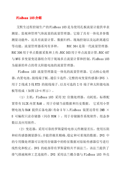
FloBoss103介绍艾默生过程控制生产的FloBoss103是为使用孔板流量计提供单表测量、监视和管理气体流量的流量管理器。
它除了具有一体化多参数测量功能外,还具有流量计算、数据归档、现场控制以及远距离通信等功能。
流量管理器系列有多种,ROC364是第一代流量管理器,ROC306用于单点数据采集和上传,ROC503用于单点流量计算,ROC407与MVS多变量变送器组合用于现场多点流量计算和控制。
FloBoss103为最新的单点的带太阳能电池的流量管理器。
FloBoss103流量管理器是一体化的流量管理器。
它由核心处理器、内置电池、接线端子板、通信卡选件、完整的双变量传感器(DVS)、用于2线或3线RTD的接线端子、以及可选的I/O端子和太阳能电池板等组成(如图13-4所示)。
(1)主机:FloBoss103采用32位微处理器,功耗低。
标准配置带有512K内置RAM,用于存储当前数据和历史数据。
它采用小型锂电池为RAM提供后备电源(寿命5年)。
FloBoss装置还带有2MB×8可编程只读存储器(闪存ROM),用于存储操作系统软件、组态参数以及应用软件。
(2)变送器:采用可靠的罗斯蒙特电容元件测量差压,使用压阻和硅传感器测量静压,并提供极其精确、稳定和可重现的数据。
DVS中的专用微处理器可以使用存储器中的特征数据对原始传感器信号进行线性化和校正。
DVS的底部带有罗斯蒙特共平面法兰,该法兰提供了排气排液阀和工艺连接件。
DVS采用法兰耦合器与FloBoss103外壳连接。
(3)ROCLINK软件:个人计算机上运行ROCLINK软件可以对FloBoss进行组态并监视其运行。
现场输入/输出(I/O)、DVS输入、流量计算、历史日志以及所有其他功能都是采用ROCLINK for Windows 组态软件进行现场配置。
(4)标准接线端子板:提供多种流量管理器的线路连接,包括:RTD输入、LOI通信端口、RS485通信端口、通信卡选件、I/O以及电源单元。
AOZ1036PI规格书
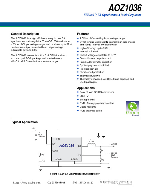
Recommended Operating Conditions
The device is not guaranteed to operate beyond the Maximum Recommended Operating Conditions.
Symbol
Parameter
Conditions
Min.
Typ.
Max Units
VIN VUVLO
IIN
Supply Voltage
Input Under-voltage Lockout Threshold
Supply Current (Quiescent)
IOFF
Shutdown Supply Current
Package 5x4 DFN-8 Exposed Pad SO-8
Environmental Green Product
AOS Green Products use reduced levels of Halogens, and are also RoHS compliant. Please visit /web/quality/rohs_compliant.jsp for additional information.
50°C/W 50°C/W
Note:
2. The value of ΘJA is measured with the device mounted on 1-in2 FR-4
board with 2oz. Copper, in a still air environment with TA = 25°C. The value in any given application depends on the user's specific board
LM103UPS电源专用说明书
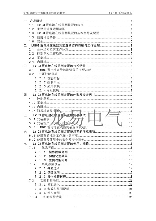
一产品概述 (4)1.1LM103蓄电池在线监测装置的特点 (4)1.2主要用途及适用范围 (4)1.3LM103蓄电池在线监测装置的基本型号及配置 (4)1.5使用环境条件 (5)1.6安全 (5)二LM103蓄电池在线监测装置的结构特征与工作原理 (6)2.1总体结构及其工作原理 (6)2.2控制单元工作原理 (7)2.3采集模块 (7)2.4内阻模块 (7)三LM103蓄电池在线监测装置的技术特性 (8)3.1LM103蓄电池在线监测装置的主要功能 (8)3.2主要性能指标 (8)3.2.1性能指标 (8)3.2.2控制单元 (9)3.2.3采集模块 (9)3.2.4内阻模块 (9)四LM103蓄电池在线监测装置的外形及安装尺寸 (10)4.1控制单元 (10)4.2采集模块 (10)4.3内阻模块 (11)龙易电气4.4简易机架尺寸图 (11)五LM103蓄电池在线监测装置的安装调试 (13)5.1安装要求 (13)5.2安装程序、方法及注意事项 (13)5.3LM103蓄电池在线监测装置的试运行 (13)六LM103蓄电池在线监测装置使用前的注意事项 (14)6.1使用前的准备工作及注意事项 (14)6.2使用前及使用中的安全及安全防护 (14)七LM103蓄电池在线监测装置的使用、操作 (15)7.1熟悉界面 (15)7.1.1操作面板介绍 (15)7.1.2初始化主菜单 (15)7.1.3主要功能简介 (16)7.2系统参数设置 (17)7.2.1界面进入 (17)7.2.2参数说明 (17)7.2.3具体操作过程 (19)7.3实时监测功能 (21)7.3.1界面进入 (21)7.3.2参数与界面说明 (21)7.3.3操作介绍 (22)7.4实时报警查询 (23)7.4.1界面进入 (23)7.4.2界面介绍 (24)7.4.3操作简介 (24)7.5时间更改 (24)7.5.1进入界面 (24)7.5.2界面介绍 (25)7.5.3操作步骤 (25)7.6密码更改 (26)7.6.1操作简介 (26)八常见故障分析与排除 (27)8.1装置上指示灯说明 (27)8.2故障与排除 (27)九保养维护 (29)9.1运行时的维护 (29)9.2正常维修程序 (29)十运输与贮存时的注意事项 (29)10.1运输时的注意事项 (29)10.2贮存时注意事项 (29)十一服务与支持 (29)附录1产品的基础知识 (30)1.1蓄电池的相关概念 (30)1.2电池失效 (31)龙易电气1.3电池的日常维护 (32)1.4蓄电池检测方法 (33)1.5蓄电池检查 (33)非常感谢您采购和使用本产品,如在使用中出现疑问,欢迎来电咨询或登陆我们的网站:。
MPW1036中文资料
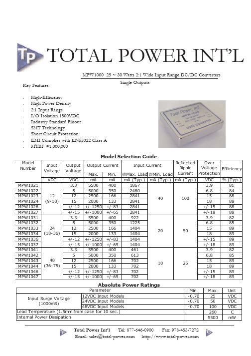
Model Number Input Voltage VDC MPW1021 MPW1022 MPW1023 MPW1024 MPW1026 MPW1027 MPW1031 MPW1032 MPW1033 MPW1034 MPW1036 MPW1037 MPW1041 MPW1042 MPW1043 MPW1044 MPW1046 MPW1047 Output Voltage VDC 3.3 5 12 15 +/-12 +/-15 3.3 5 12 15 +/-12 +/-15 3.3 5 12 15 +/-12 +/-15 Output Current Max. mA 5500 5000 2500 2000 +/-1250 +/-1000 5500 5000 2500 2000 +/-1250 +/-1000 5500 5000 2500 2000 +/-1250 +/-1000 Min. mA 400 350 166 133 +/-83 +/-65 400 350 166 133 +/-83 +/-65 400 350 166 133 +/-83 +/-65 Reflected Over Ripple Voltage Efficiency @Max. Load @Min. Load Current Protection mA (Typ.) mA (Typ.) mA (Typ.) VDC % (Typ.) 1867 3.9 81 2480 6.8 84 2841 15 88 40 100 2841 18 88 2841 +/-15 88 2841 +/-18 88 922 3.9 82 1225 6.8 85 1404 15 89 20 50 1404 18 89 1404 +/-15 89 1404 +/-18 89 461 3.9 82 613 6.8 85 702 15 89 10 25 702 18 89 702 +/-15 89 702 +/-18 89 Input Current Min. -0.70 -0.70 -0.70 Max. 25 50 100 260 5500 Unit VDC VDC VDC C mW
飞龙 wi
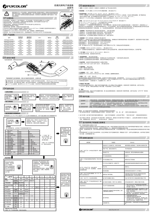
持续电流(散热良好)瞬间电流(散热良好)BEC尺寸(供参考)重量(供参考)20A 30A 40A 60A 30A 40A 55A 80A 锂电池型号79g 35g 36g 76g 49x23.5x13.5mm 65.5x34x21mm● 反推功能,支持飞行过程中切换电机正反向,达到减速目的(WinDragon wifi 80-130A 支持此功能)。
2-4S 2-4S 2-6S 2-6S 8.4V/7.4V/6V/5V ,5A 80A 100A 119g 2-6S 100A 120A 125g 2-6S 130A150A130g82.5x39.5x23.5mm2-6S航模无刷电子调速器WinDragon wifi 130AWinDragon wifi 100A WinDragon wifi 80A WinDragon wifi 60A WinDragon wifi 30A WinDragon wifi 40A WinDragon wifi 20A 8.4V/7.4V/6V/5V ,5A 8.4V/7.4V/6V/5V ,5A 8.4V/7.4V/6V/5V,5A8.4V/7.4V/6V/5V ,5A 82.5x39.5x23.5mm 82.5x39.5x23.5mm 65.5x34x21mm 49x23.5x13.5mm 02 产品规格04 操作说明1.正常工作模式2.油门行程设定3.通过遥控器进行参数编程设定推荐使用Flycolor Wi-Fi Trans 通过Flycolor App 进行参数编程设定。
另外可通过编程卡进行参数编程设定1. 刹车: [1] 无刹车 [2]软刹车 [3]重刹车 [4]很重刹车 (出厂默认值为无刹车)2.电池类型: [1]LiPo(锂电) [2] NiCb/NiMh(镍氢/镍隔) (默认值为Li Po )3.低压保护阈值:低/中/高 [1] 2.8V [2]3.0V [3]3.2V ;默认值为中(3.0V)对于Ni-xx电池组:低/中/高中止电压是电池组初始电压值的50%/65%/75%对于Li-xx电池组:可自动计算电池数量,除了确定电池 类型外无需用户设置。
F-103 LSC6400系列重型远程平台称量器说明书

F-103HEAVY-DUTY REMOTE PLATFORM SCALESDURABLE, POWDER COATED OR STAINLESS STEELLSC6400 SeriesCapacities from 100 to 1000 lb (45 to 455 kgf)ߜShipping and Manifest SystemsߜIn-Line Weighing and Checkweighing ߜParts Counting or WeighingߜIn-Motion Weighing SystemsߜGeneral PurposeWeighing ApplicationsWith their rugged design and high 1 part in 5000 accuracy, the LSC6400 Series platform scales are ideal for industrial applications.Standard features include ranges from 100 to 1000 lb, durable powder-coated or stainless steel platforms, positive overload protection, full-frame design, and adjustable leveling feet.Excitation:15V max Linearity:0.01% Hysteresis:0.02%Connection:3 m (10') cable Shipping Weight:18 x 18":30 kgf (65 lb)18 x 24":34 kgf (75 lb)24 x 24":39 kgf (85 lb)Construction:STD: Mild steel with premium powder coated platformSS: All stainless steel (frame and platform) with environmentally sealed load cellLSC6400-2424-100,scale, $845, shown much smaller than actual size.Starts atHEAVY-DUTY REMOTE PLATFORM SCALESMOST POPULAR MODELS HIGHLIGHTED!To Order (Specify Model Number)WM7600, weighmeter, $645,shown smaller than actual size, see page F-107.CANADA www.omega.ca Laval(Quebec) 1-800-TC-OMEGA UNITED KINGDOM www. Manchester, England0800-488-488GERMANY www.omega.deDeckenpfronn, Germany************FRANCE www.omega.frGuyancourt, France088-466-342BENELUX www.omega.nl Amstelveen, NL 0800-099-33-44UNITED STATES 1-800-TC-OMEGA Stamford, CT.CZECH REPUBLIC www.omegaeng.cz Karviná, Czech Republic596-311-899TemperatureCalibrators, Connectors, General Test and MeasurementInstruments, Glass Bulb Thermometers, Handheld Instruments for Temperature Measurement, Ice Point References,Indicating Labels, Crayons, Cements and Lacquers, Infrared Temperature Measurement Instruments, Recorders Relative Humidity Measurement Instruments, RTD Probes, Elements and Assemblies, Temperature & Process Meters, Timers and Counters, Temperature and Process Controllers and Power Switching Devices, Thermistor Elements, Probes andAssemblies,Thermocouples Thermowells and Head and Well Assemblies, Transmitters, WirePressure, Strain and ForceDisplacement Transducers, Dynamic Measurement Force Sensors, Instrumentation for Pressure and Strain Measurements, Load Cells, Pressure Gauges, PressureReference Section, Pressure Switches, Pressure Transducers, Proximity Transducers, Regulators,Strain Gages, Torque Transducers, ValvespH and ConductivityConductivity Instrumentation, Dissolved OxygenInstrumentation, Environmental Instrumentation, pH Electrodes and Instruments, Water and Soil Analysis InstrumentationHeatersBand Heaters, Cartridge Heaters, Circulation Heaters, Comfort Heaters, Controllers, Meters and SwitchingDevices, Flexible Heaters, General Test and Measurement Instruments, Heater Hook-up Wire, Heating Cable Systems, Immersion Heaters, Process Air and Duct, Heaters, Radiant Heaters, Strip Heaters, Tubular HeatersFlow and LevelAir Velocity Indicators, Doppler Flowmeters, LevelMeasurement, Magnetic Flowmeters, Mass Flowmeters,Pitot Tubes, Pumps, Rotameters, Turbine and Paddle Wheel Flowmeters, Ultrasonic Flowmeters, Valves, Variable Area Flowmeters, Vortex Shedding FlowmetersData AcquisitionAuto-Dialers and Alarm Monitoring Systems, Communication Products and Converters, Data Acquisition and Analysis Software, Data LoggersPlug-in Cards, Signal Conditioners, USB, RS232, RS485 and Parallel Port Data Acquisition Systems, Wireless Transmitters and Receivers。
FP103_中文应用资料
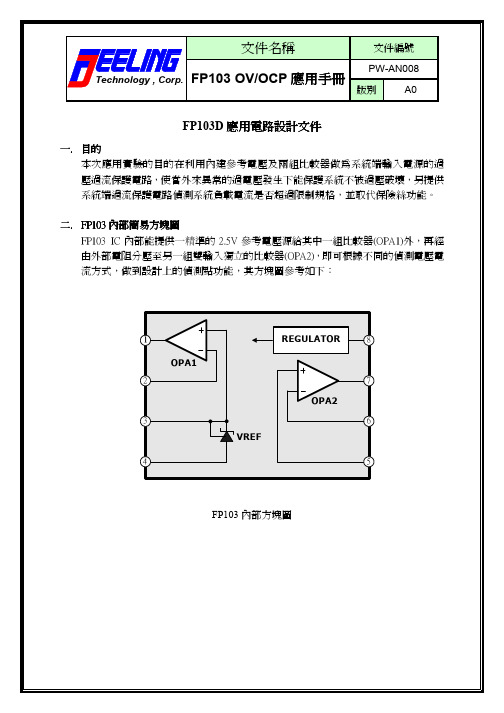
1 OPA1 2
REGULATOR
8
7 OPA2
3 VREF 4
6
5
FP103 內部方塊圖
文件名稱
Technology , Corp.
文件編號 PW-AN008 版別 A0
FP103 OV/OCP 應用手冊
三. 電路說明 輸入電源過電壓偵測保護電路
CN2 1 2 Input D1 1N4148 1 R1 3.3K 2 3 4 R2 2K C3 C4 R7 91K 220u 0.1u R11 3K R12 15K Q1 S1 S2 S3 G D4 D3 D2 D1 8 7 6 5 CN1 1 2 Output
文件名稱
Technology , Corp.
文件編號 PW-AN008 版別 A0
FP103 OV/OCP 應用手冊
FP103D 應用電路設計文件
一. 目的 本次應用實驗的目的在利用內建參考電壓及兩組比較器做為系統端輸入電源的過 壓過流保護電路,使當外來異常的過電壓發生下能保護系統不被過壓破壞,另提供 系統端過流保護電路偵測系統負載電流是否超過限制規格,並取代保險絲功能。 二. FP103 內部簡易方塊圖 FP103 IC 內部能提供一精準的 2.5V 參考電壓源給其中一組比較器(OPA1)外,再經 由外部電阻分壓至另一組雙輸入獨立的比較器(OPA2),即可根據不同的偵測電壓電 流方式,做到設計上的偵測點功能,其方塊圖參考如下:
護就會動作,其電阻值大小與保護電流值有關,由下面公式可決定過流偵測的保護點: 12.43mV R10 = ----- 公式(3) I OC 因為我們已由公式(2)設計出過流偵測的參考電壓,可知當我們選定 R10 為 5.1mΩ時, 過電流保護點為
产品管理-魏德米勒继电器产品详细目录
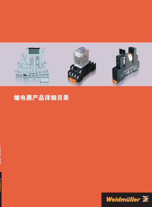
继电器产品目 录光电耦合器产品电子式时间继电器功能电子产品通讯电子产品250V/6A 12V/100mA 6.2ms/3.9ms AgSnO 2 20x106 次 0.1Hz LED 绿色/有/有 -25 °C…+55 °C -40 °C…+60 °C 40°C/93% 湿度无冷凝 CE, cURus EN 50178 300 V 4 kV ≥5.5mm III 2 是 mm 2 mm 2.5 / 0.5 / 4 1.5 / 0.5 / 2.5 93.0 / 6.1 / 92.094.0 / 6.1 / 91.0 电压 [A ] 电流 [A] 电流 [A] 电流 [A]acc.to DC 13 输出参数应用额定参数绝缘基座参数 (EN 50 178)尺寸螺钉连接弹片连接最大切换电压AC/电流 最小切换电压/电流响应时间/释放时间 触点材料 机械寿命 额定负载下的最大开关频率 状态指示/二极管/反向电压保护环境工作温度存储温度环境温度认证标准额定电压额定浪涌电压接点间爬电距离过压等级污染等级符合VDE 0106 101安全隔离 接线范围(额定/最小/最大) 长x 宽x 高负载特性曲线开关次数 开关次数1对转换触点· 该继电器可用于联接控制信号与执行器· 插拔式横联可减少联线· 6.1mm 厚· 可采用弹片式或压线框联接· 可提供镀金触头继电器(感性负载)1继电器5mA4mA190mW29V/11V29V/11V2.2mA/1.3mA2.2mA/1.3mAMRZ 48Vuc 1CO8556110000RSS 113048 48Vdc-Rel1U40616200003.3mA200mW35V/11V1.6mA/0.6mAMRZ 60Vdc 1CO8556130000RSS 113060 60Vdc-Rel1U40616300003.5mA3.5mA0.42mW71V/22V71V/22V1.8mA/0.5mA1.8mA/0.5mAMRZ 120Vuc 1CO8556100000RSS 113060 60Vdc-Rel1U40616300007.6mA1.75VA103V/49V5mA/2.5mAMRZ 230Vac 1CO8556090000RSS 113024 24Vdc-Rel1U4060120000螺钉连接型号订货号弹片连接型号订货号型号订货号38.5mA193mW3.2V/1.6V21.6mA/8mAMRZ 5Vdc 1CO8556150000RSS 113005 05Vdc-Rel1U406158000017mA210mW6.4V/2.5V8.4mA/2.4mAMRZ 12Vdc 1CO8556140000RSS 113012 12Vdc-Rel1U40616100006.6mA160mW15.4V/6.5V4mA/1.2mAMRZ 24VDC 1CO853*******RSS 113024 24Vdc-Rel1U406012000011mA6.4mA154mW15.8V/7V15.8V/7V3.6mA/1.3mA3.6mA/1.3mAMRZ 24Vuc 1CO8556120000RSS 113024 24Vdc-Rel1U4060120000 订货数据订货数据配件,插拔式继电器订货数据输入额定电压额定电流AC额定电流DC额定功率动作/释放电压AC 线圈动作/释放电压DC 线圈动作/释放电流AC 线圈动作/释放电流DC 线圈螺钉连接型号订货号弹片连接型号订货号型号订货号订货数据订货数据配件,插拔式继电器订货数据输入额定电压额定电流AC额定电流DC额定功率动作/释放电压AC 线圈动作/释放电压DC 线圈动作/释放电流AC 线圈动作/释放电流DC线圈6.6mA160mW15.4V/6.5V4mA/1.2mAMRZ 24Vdc ACT8660910000RSS 113024 24Vdc-Rel1U40601200007mA0.84VA79V/65V4.5mA/3.7mA15.6mA3.59VA117.5V/59V9.13mA/4.78mAMRZ 120Vac 1CO RC8825960000RSS 113060 60Vdc-Rel1U4061630000螺钉连接型号订货号弹片连接型号订货号型号订货号订货数据订货数据配件,插拔式继电器订货数据特殊产品输入额定电压额定电流AC额定电流DC额定功率动作/释放电压AC线圈动作/释放电压DC 线圈动作/释放电流AC 线圈动作/释放电流DC 线圈3.5mA2.5mA0.8VA /600MW146V/124V155V/1.5V1.9mA/1.5mA1.9mA/1.0mAMRZ 230Vuc 1CO8825980000RSS 113060 60Vdc-Rel1U40616300002继电器RSS 113024 24Vdc-Rel1U40601200002个转换触点250V/6A12V/10mA7ms/3msAgNi20x106次0.1HzLED 绿色/有/有-25 °C…+60 °C-40 °C…+80 °C5%...95% 湿度无冷凝CEEN 50178300 V4 kV≥5.5mmIII2是mm2mm2.5 / 0.5 / 494.2 / 14 / 94.016.7mA500mW16.8V/2.4V3.2mA0.75VA172.5V/34.5V订货数据· 该继电器可用于联接控制信号与执行器· 插拔式横联可减少联线· 14mm厚· 采用弹片式联接输出参数额定参数绝缘基座参数 (EN 50 178)尺寸弹片连接最大切换电压AC/电流最小切换电压/电流响应时间/释放时间触点材料机械寿命额定负载下的最大开关频率状态指示/二极管/反向电压保护环境工作温度存储温度环境温度认证标准额定电压额定浪涌电压接点间爬电距离过压等级污染等级符合VDE 0106 101安全隔离接线范围(额定/最小/最大)长x宽x高弹片连接型号订货号订货数据输入额定电压额定电流AC额定电流DC额定功率动作/释放电压AC 线圈动作/释放电压DC 线圈动作/释放电流AC 线圈动作/释放电流DC 线圈3继电器· 该继电器可用于联接控制信号与执行器· 插拔式横联可减少联线· 14mm厚· 采用弹片式联接250V/6A(输出并联可达10A)12V/10mA7ms/3msAgNi20x106次0.1HzLED 绿色/有/有-25 °C…+60 °C-40 °C…+80 °C5%...95% 湿度无冷凝CEEN 50178300 V4 kV≥5.5mmIII2是mm2mm2.5 / 0.5 / 494.2 / 14 / 94.016.7mA500mW16.8V/2.4V3.2mA0.75VA172.5V/34.5V订货数据输出参数额定参数绝缘基座参数 (EN 50 178)尺寸弹片连接最大切换电压AC/电流最小切换电压/电流响应时间/释放时间触点材料机械寿命额定负载下的最大开关频率状态指示/二极管/反向电压保护环境工作温度存储温度环境温度认证标准额定电压额定浪涌电压接点间爬电距离过压等级污染等级符合VDE 0106 101安全隔离接线范围(额定/最小/最大)长x宽x高弹片连接型号订货号订货数据输入额定电压额定电流AC额定电流DC额定功率动作/释放电压AC 线圈动作/释放电压DC 线圈动作/释放电流AC 线圈动作/释放电流DC 线圈4继电器250V/6A12V/10mA6.6ms/5.8msAgSnO2 5μm Au20x106次0.1HzLED 绿色/有/有-25 °C…+55 °C-40 °C…+60 °C40°C/93% 湿度无冷凝CE, cURusEN 50178300 V4 kV≥5.5mmIII2是mm2mm2.5 / 0.5 / 4 1.5 / 0.5 / 2.593.0 / 6.1 / 92.094.0 / 6.1 / 91.06.6mA160mW15.4V/6.5V4mA/1.2mAMRZ 24Vdc 1CO 5uAu8596080000RSS 112024 24Vdc-Rel1U40615900003.5mA3.5mA0.42VA71V/22V71V/22V1.8mA/0.5mA1.8mA/0.5mAMRZ 120Vuc 1CO 5uAu8652040000RSS 112060 60Vdc-Rel1U40616000007.6mA1.75VA103V/49V5mA/2.5mAMRZ 230Vac 1CO 5uAu8596070000RSS 112024 24Vdc-Rel1U4061590000订货数据· 该继电器可用于联接控制信号与执行器· 插拔式横联可减少联线· 6.1mm厚· 可采用弹片式或压线框联接· 可提供镀金触头继电器输出参数额定参数绝缘基座参数 (EN 50 178)尺寸螺钉连接弹片连接最大切换电压AC/电流最小切换电压/电流响应时间/释放时间触点材料机械寿命额定负载下的最大开关频率状态指示/二极管/反向电压保护环境工作温度存储温度环境温度认证标准额定电压额定浪涌电压接点间爬电距离过压等级污染等级符合VDE 0106 101安全隔离接线范围(额定/最小/最大)长x宽x高螺钉连接型号订货号弹片连接型号订货号型号订货号订货数据订货数据配件,插拔式继电器输入额定电压额定电流AC额定电流DC额定功率动作/释放电压AC 线圈动作/释放电压DC 线圈动作/释放电流AC 线圈动作/释放电流DC 线圈5继电器该继电器可用于连接控制信号和执行器,适用于中小型负载继电器横块可更换6.1 mm厚插拔式横联件可减少接线Cl.1 Div.2区域的防爆认证••••技术参数6光电耦合器该继电器可用于连接控制信号和执行器,适用于中小型负载继电器横块可更换6.1 mm厚插拔式横联件可减少接线Cl.1 Div.2区域的防爆认证120 VAC的继电器RC组合模块,输入端的RC组合电路可以保证安全切换,例如可防止漏电流的影响。
WH-BLE103 硬件设计手册说明书

WH-BLE103 硬件设计手册文件版本:V1.0.0目录WH-BLE103 硬件设计手册 (1)1关于文档 (3)1.1. 文档目的 (3)1.2. 产品外观 (3)1.3. 参考文档列表 (3)2产品简介 (4)2.1. 基本参数 (4)2.2. 模块应用框图 (4)2.3. 引脚定义 (5)2.4. 开发套件 (6)3硬件参考设计 (7)3.1.外围电路框架参考 (7)3.2.电源接口 (7)3.3. UART接口 (7)3.4.复位控制和恢复出厂设置控制 (8)3.5.低功耗唤醒引脚 (9)3.6.射频接口 (9)4电气特性 (11)4.1.工作存储温度 (11)4.2.输入电源 (11)4.3.模块IO口电平 (11)4.4. IO驱动电流 (11)5机械特性 (12)5.1.回流焊建议 (12)5.2.外形尺寸 (13)6联系方式 (15)7免责声明 (16)8更新历史 (17)1 关于文档1.1. 文档目的本文详细阐述了WH-BLE103无线模块的基本功能和主要特点、硬件接口及使用方法、结构特性等电气指标。
通过阅读本文档,用户可以对本产品有整体认识,对产品规格参数有明确了解,顺利将模块嵌入各种终端设计中。
1.2. 产品外观图片1实物图1.3. 参考文档列表除此硬件开发文档外,我们同时提供了基于本产品的说明书、规格书、封装库等资料,方便用户设计参考,客户可到官方网站查看下载:/download/228.html/download/222.html/download/manual/231.html2产品简介2.1 . 基本参数表格 1 参数列表分类 参数取值无线参数工作频段 2402~2480MHz 发射功率 -19dBm - +8dBm 接收灵敏度 -78dBm传输距离(空旷,无干扰) 模块+模块:120m MAX模块+手机:80m MAX (备注:距离与手机有关) 天线选项 板载天线、焊盘 硬件参数数据接口 UART :1200~2Mbps 工作电压1.7V ~ 3.6V工作电流平均***********从机待机不休眠平均***********主机待机不休眠 平均***********广播不休眠 平均************从机深度睡眠 平均************广播深度睡眠工作温度 -40℃ ~ +85℃ 存储温度 -40℃ ~ +85℃ 工作湿度 5~95%RH(无凝露) 存储湿度 5~95%RH(无凝露)尺寸 尺寸:10mm x 10mm x 2mm 封装接口SMT 表贴2.2 . 模块应用框图目前模块开放的接口包括:电源、串口、射频接口和部分IO 口等,如下图所示。
Silvertel Ag103 试验板用户指南说明书

Silvertel1 Table of Contents1Table of Contents 1 2Table of Figures 1 3Introduction 2 4Board Description 2 4.1Input (2)4.2Output (3)4.3Capacity Selection (3)4.4Simulated Thermal Offset (4)4.5Status Output (4)4.5.1Mode 0 – Bulk Charge Operation 54.5.2Mode 1– Float Charge 54.5.3Mode 2 – Over Current 54.5.4Mode 3 – Over Temperature 54.5.5Mode 4 – Disconnected battery 54.5.6Mode 5 - Input Voltage Removed/ No Solar Power 6 5Using the Board 6 6EVALAg103 Evaluation Board Schematic 7 2 Table of FiguresFigure 1: Board Layout (2)Figure 2: Capacity selection link (3)Figure 3: Example set-up (6)Figure 4: EVALAg103 R1 Schematic (7)3 IntroductionThis manual is a guide to using the “EVALAg103” (Rev R1) evaluation board with our Ag103 Sealed Lead Acid (SLA) solar battery charger module. The EVALAg103 evaluation board can be powered by either a 21V open circuit solar panel, or a bench power supply with a range of 9V to 36V. This will charge SLA batteries with a capacity between 1.2Ah and 12Ah.4 Board Description4.1 InputThe input power is supplied to the board through connector J1 or J2 (see Figure 1). J1 is a standard 2.5mm DC10 connector with the centre pin of the connector being positive and the outer is negative. J2 is a screw terminal with pin 1 as the positive input. The input current can be measured by removing LK1 and connecting an ammeter across these pins.LED1 will be illuminated when the input supply is ON.Figure 1: Board Layout4.2 OutputThe output connections to the SLA battery are made through JP2 (positive) and JP3 (negative) with added protection of F1 as a 8A fuse and D1 as a 10A diode, to protect an over current or short for either the load or battery. The Load Output connections are available through JP1 (positive) and JP4 (negative).4.3 Capacity SelectionThe EVALAg103 evaluation board can set the Ag103 capacity from 1.2Ah to 12Ah bysetting the corresponding jumper link on J3 (see Figure 2 and Table 1).Figure 2: Capacity selection linkJ6 Resistor SelectionBattery Capacity(Ah)R CSResistance(Ohms)*Min InputVoltage (V)Bulk Charge Current Limit (A) ±10%R9 1.2 1K ±1% 9 0.3 R10 2 2K ±1% 9 0.5 R11 2.1 3K ±1% 9 0.525 R12 2.3 3K9 ±1% 9 0.575 R13 2.8 4K7 ±1% 9 0.7 R14 3.2 6K2 ±1% 12 0.8 R15 4 6K8 ±1% 12 1 R16 7 7K5 ±1% 12 1.2 R17 12 9K1 ±1%121.2Table 1: Output ConnectionsNote: to prevent damaging the battery it is important that the correct value of RCS is set. If the selector link is not fitted, then the Ag103 will default to 1.2Ah capacity.4.4 Simulated Thermal OffsetDuring Float charge SW1 can be used to demonstrate how the voltage changes to compensate for the change in battery temperature if an appropriate thermistor is fitted. With both switch positions open, the Ag103 will default to a 25ºC ambient charge voltage.When switch No. 1 is closed, placing R7 (20K) to ground, this will simulate a battery temperature higher than 25ºC and the output voltage will decrease (this response will be slow when the Ag103 is float charging).When switch No. 2 is closed, placing R8 (220K) to ground, this will simulate a battery temperature lower than 25ºC and the output voltage will increase.When both switches are closed this will simulate a battery temperature higher than 50ºC, the output will switch OFF and the Status LED (2) will flash in mode 3. Opening one or both switches will return the Ag103 to its normal charge mode.4.5 Status OutputThe Ag103 has a status indication output pin ‘STAT’; that can be either connected to a µ-controller input for full status monitoring, via connector J4, or can be used with an LED as an indicator by fitting a link on LK2.If LK2 is fitted then LED 2 will be illuminated with the sequences detailed below and shown in Table 2: -Mode Status Mode STAT Output0 Bulk Charge Operation Steady State ‘Logic 1’1 Float Charge 50% ‘Logic 1’ 50% ‘Logic 0’2 Over Current Error 1 Pulse3 Over Temperature Error 2 Pulses4 Disconnected Battery Error 3 Pulses5 Input Voltage Removed / No Solar Power Steady State ‘Logic 0’Table 2: STAT Output Conditions*For further information on the timing of the STAT output please see Figure 8 of the Ag103 datasheet.4.5.1 Mode 0 – Bulk Charge OperationOnce the Ag103 has checked the battery capacity and sees a 12V battery connected it will power up and the ‘STAT’ pin will output a steady state 'logic 1'.The Ag103 will continue to output this state until the battery has reached it's 80% charge before switching to float charge and enters Mode 1.4.5.2 Mode 1– Float ChargeAfter the battery has reached it's 80% charge the Ag103 will change it's charging status to float charge by dropping it's terminal voltage down to ~13.65V. The 'STAT' pin will drop to a logic 0 for 1s and then back to a logic 1 for 1s. This cycle will repeat itself over the period of its float charge.4.5.3 Mode 2 – Over CurrentIf an output over current condition is detected, the Ag103 will shutdown its DC-DC converter and will go into Mode 2. The STAT pin will drop to a logic 0 for 100ms, followed by a logic 1 for 100ms before returning to a logic 0. The Ag103 will then reset and wait 2 seconds before re-attempting to power up. If the over current is still there when trying to power up, the Ag103 will immediately shut back down and repeat the process. Once the over current has been removed the Ag103 will return to Mode 0 (bulk charge operation).4.5.4 Mode 3 – Over TemperatureIf a battery over temperature condition occurs, the Ag103 will shutdown its DC-DC converter to protect the battery and enter Mode 3. The STAT pin will drop to a logic 0 for 100ms before generating two logic 1 pulses, with a 100ms mark and 100ms space. This will repeat over a 2s period until the battery temperature has dropped below 50˚C (the maximum operating temperature). Once the battery temperature has dropped below 50˚C the Ag103 will return to Mode 0 (bulk charge operation).4.5.5 Mode 4 – Disconnected batteryIf the battery is disconnected or there is no battery present at power up, the Ag103 will shutdown its DC-DC converter, go into Mode 4 and output three 100ms logic 1 pulses, with a 100ms mark and 100ms space. This will repeat over a 2s period until a 12V battery is connected. When a 12V battery is connected the Ag103 will go into Mode 0 (bulk charge operation).4.5.6 Mode 5 - Input Voltage Removed/ No Solar PowerWhen the input voltage is removed or the solar panel can no longer provide any power to the Ag103, the STAT pin will output a logic 0 until power has been reconnected or the panel can provide enough power to charge the connected battery.5 Using the BoardFigure 3 shows an example set-up using the Ag103 to charge a 12Ah SLA battery from a solar panel. For a 12Ah battery the J3 link is set to the R17 position.Figure 3: Example set-up6 EVALAg103 Evaluation Board SchematicFigure 4: EVALAg103 R1 Schematic。
NW103系列MEMS压力传感器芯片

典型值 5
150、400 1.8 x 1.8
5 0 100 100 ±0.2 +600 -2200 ---------
最大值 10
5.5 +30 130 130 ±0.5 +800 -1800 60 ±0.2 ±0.2 ±0.2 3X 5X 150 150
单位 V(DC)
KPa mm2 KΩ mV mV mV %FS ppm/℃ ppm/℃ μV/℃ %FS %FS %FS
NW103 系列
Nano MEMS Inc.
压力传感器芯片
产品特点
应用领域
芯片尺寸:1.8 x 1.8 mm2 工作温度:-40℃~150℃ 量 程:150KPa、400KPa
工业/工程控制 消费电子 绝/差压传感器系统
产品简介
NW103 系列产品是由无锡市纳微电子有限公司提供的扩散硅压阻式压力传感器。本系列产品具有与被 检测压力成良好线性关系的毫伏级输出信号及优异的重复性与稳定性,适用于陶瓷、PCB、TO 管等多种封 装形式。NW103 系列产品采用 SOI 材料实现桥阻与衬底的介质隔离,提高了芯片的工作温度,适用于壁挂 炉、电压力锅等高温应用环境。
3 2 1
①芯片尺寸
01
1.0 x 1.0 mm2
02
1.6 x 1.6 mm2
03
1.8 x 1.8 mm2
04
2.0 x 2.0 mm2
05
3.0 x 3.0 mm2
②压力类型
X
绝压/差压
A
绝压
D
差压
③工作压力范围
0005
5KPa
0040
40KPa
0100
100KPa
MODEL970-1036中文资料
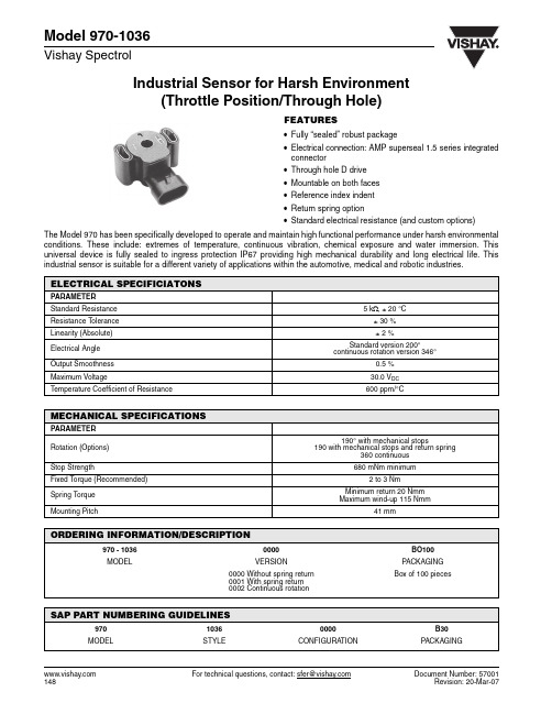
Industrial Sensor for Harsh Environment(Throttle Position/Through Hole)Model 970-1036Vishay Spectrol For technical questions, contact: sfer@Document Number: 57001FEATURES•Fully “sealed” robust package•Electrical connection: AMP superseal 1.5 series integrated connector•Through hole D drive •Mountable on both faces •Reference index indent •Return spring option•Standard electrical resistance (and custom options)The Model 970 has been specifically developed to operate and maintain high functional performance under harsh environmental conditions. These include: extremes of temperature, continuous vibration, chemical exposure and water immersion. This universal device is fully sealed to ingress protection IP67 providing high mechanical durability and long electrical life. Thisindustrial sensor is suitable for a different variety of applications within the automotive, medical and robotic industries.ELECTRICAL SPECIFICIATONSPARAMETER Standard Resistance 5 k Ω, ± 20 °C Resistance Tolerance ± 30 %Linearity (Absolute)± 2 %Electrical Angle Standard version 200°continuous rotation version 346°Output Smoothness 0.5 %Maximum Voltage30.0 V DC Temperature Coefficient of Resistance600 ppm/°CMECHANICAL SPECIFICATIONSPARAMETER Rotation (Options)190° with mechanical stops190 with mechanical stops and return spring360 continuousStop Strength680 mNm minimumFixed Torque (Recommended) 2 to 3 NmSpring Torque Minimum return 20 Nmm Maximum wind-up 115 NmmMounting Pitch41 mmORDERING INFORMATION/DESCRIPTION970 - 10360000BO100MODELVERSIONPACKAGING 0000 Without spring return 0001 With spring return 0002 Continuous rotationBox of 100 piecesSAP PART NUMBERING GUIDELINES97010360000B30MODELSTYLECONFIGURATIONPACKAGINGModel 970-1036Industrial Sensor for Harsh Environment(Throttle Position/Through Hole)Vishay SpectrolDocument Number: 57001For technical questions, contact: sfer@DIMENSIONS in inches (millimeters)ENVIRONMENTAL SPECIFICATIONSPARAMETER Vibration 15 g thru 2000 HzShock 50 gRotational Life 5000000 full cycles10000000 dither cycles (second rotation)Load Life900 h T emperature Range - 40 °C to + 130 °CSealing IP67Humidity 96 % at 40 °C (500 h)Salt Spray5 % solution at 40 °C (300 h)MARKINGUnit IdentificationManufacturer’s name and model number, resistance value, tolerance, data code and terminal identificationDisclaimer Legal Disclaimer NoticeVishayAll product specifications and data are subject to change without notice.Vishay Intertechnology, Inc., its affiliates, agents, and employees, and all persons acting on its or their behalf (collectively, “Vishay”), disclaim any and all liability for any errors, inaccuracies or incompleteness contained herein or in any other disclosure relating to any product.Vishay disclaims any and all liability arising out of the use or application of any product described herein or of any information provided herein to the maximum extent permitted by law. The product specifications do not expand or otherwise modify Vishay’s terms and conditions of purchase, including but not limited to the warranty expressed therein, which apply to these products.No license, express or implied, by estoppel or otherwise, to any intellectual property rights is granted by this document or by any conduct of Vishay.The products shown herein are not designed for use in medical, life-saving, or life-sustaining applications unless otherwise expressly indicated. Customers using or selling Vishay products not expressly indicated for use in such applications do so entirely at their own risk and agree to fully indemnify Vishay for any damages arising or resulting from such use or sale. Please contact authorized Vishay personnel to obtain written terms and conditions regarding products designed for such applications.Product names and markings noted herein may be trademarks of their respective owners.元器件交易网Document Number: 。
网件(netgear)WG103简介
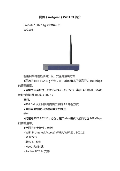
网件(netgear)WG103简介ProSafe? 802.11g无线接入点WG103智能网络特性提供可升级、安全的解决方案●高速的IEEE 802.11g协议,在Turbo模式下最高可达108Mbps 的传输速率。
●全面的安全特性,包括WPA2,多SSID,欺诈AP检测,MAC 地址过滤以及Radius 802.1x支持。
●802.3af 以太网供电提供灵活的AP部署方式●可使用高增益天线达到更大的覆盖特性●高速的IEEE 802.11g协议,在Turbo模式下最高可达108Mbps 的传输速率。
●全面的安全特性,包括:- WiFi Protected Access? (WPA/WPA2),802.11i- 多BSSID- 欺诈AP检测- MAC地址过滤- Radius 802.1x支持- WDS时使用WPA2数据加密- 禁用/启用SSID广播●丰富的SNMP功能用于高级网络管理●带有无线多模式(WMM)的服务质量(QoS)●无线多模式下的客户端省电模式(WMM-PS)●部署大范围覆盖的无线分布式系统(WDS):- 点对点桥接- 点对多点桥接- 中继- 客户端模式(未来支持)●可使用高增益天线达到更大的覆盖●坚固的带有防盗孔的金属外壳●在吊顶天花板上能安全省力的安放●支持IEEE 802.3af 以太网供电(PoE):- 不受环境限制的灵活部署AP- 供电距离可达100mi- 省去了额外敷设电源线ProSafe? 802.11g无线接入点WG103主要技术规范如下表产品名ProSafe? 802.11g无线接入点物理规格–尺寸(w x d x h):158 x 101 x 29 mm(6.22 x 3.97 x 1.14 inch)–重量:402.5 g(0.88 lb)处理器和内存–Atheros?,8 MB flash,32 MB SDRAM无线–IEEE 802.11g 54 Mbps 无线接入点–天线:5 dBi,2.4 GHz 可拆卸–典型最大功率输出(根据国家或地区选择不同有所差异):20 dBm 高级无线特性–点对点无线桥接模式–点对多点无线桥接模式–中继模式–输出功率可调整网络管理–可通过Web浏览器或SNMP(v1/v2c)远程配置和管理物理接口–一个10/100BASE-T 带Auto Uplink?的以太网(RJ45)端口,支持IEEE 802.3af 以太网供电(PoE)–天线接头:一个反向SMALED指示灯–电源、检测、LAN以及WLAN无线安全–40-bit(也叫64-bit),128-bit 有线等效加密(WEP);WiFi保护存取(WPA-PSK, WPA2-PSK)–欺诈AP侦测–IEEE 802.1x认证–MAC地址过滤–8个BSSID–防盗孔设计–安全的SSL浏览器连接–支持VLAN数:9供电需求–电源适配器:直流12V 1.0A,插头制式根据所在地区规定定制–PoE功率:5W包装内容–ProSafe 802.11g无线接入点WG103–一根5dbi可拆卸天线–资源CD–电源适配器–以太网线–安装指南保修 1 年订货号亚洲:WG103-100AUS。
LM1036N中文资料
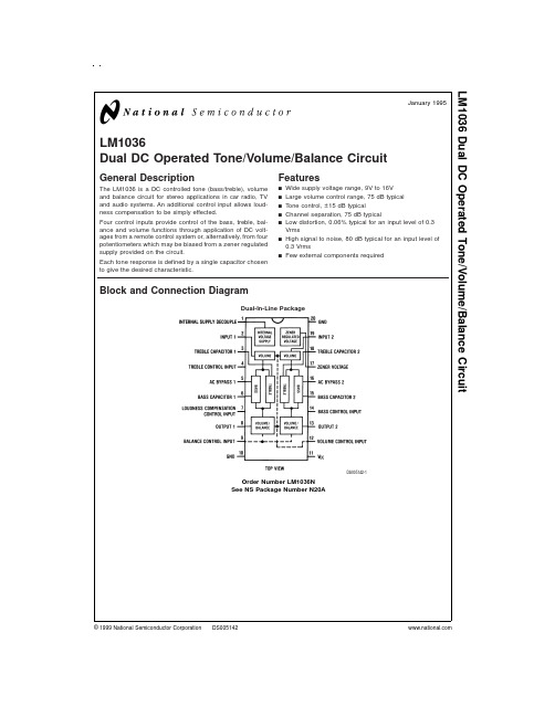
LM1036Dual DC Operated Tone/Volume/Balance CircuitGeneral DescriptionThe LM1036is a DC controlled tone (bass/treble),volume and balance circuit for stereo applications in car radio,TV and audio systems.An additional control input allows loud-ness compensation to be simply effected.Four control inputs provide control of the bass,treble,bal-ance and volume functions through application of DC volt-ages from a remote control system or,alternatively,from four potentiometers which may be biased from a zener regulated supply provided on the circuit.Each tone response is defined by a single capacitor chosen to give the desired characteristic.Featuresn Wide supply voltage range,9V to 16V n Large volume control range,75dB typical n Tone control,±15dB typicaln Channel separation,75dB typicalnLow distortion,0.06%typical for an input level of 0.3Vrmsn High signal to noise,80dB typical for an input level of 0.3Vrmsn Few external components requiredBlock and Connection DiagramDual-In-Line PackageDS005142-1Order Number LM1036N See NS Package Number N20AJanuary 1995LM1036Dual DC Operated Tone/Volume/Balance Circuit©1999National Semiconductor Corporation Absolute Maximum Ratings(Note1)If Military/Aerospace specified devices are required, please contact the National Semiconductor Sales Office/ Distributors for availability and specifications.Supply Voltage16V Control Pin Voltage(Pins4,7,9,12,14)V CC Operating Temperature Range0˚C to+70˚C Storage Temperature Range−65˚C to+150˚C Power Dissipation1W Lead Temp.(Soldering,10seconds)260˚C Note1:“Absolute Maximum Ratings”indicate limits beyond which damage to the device may occur.Operating Ratings indicate conditions for which the device is functional,but do not guarantee specific performance limits.Electrical CharacteristicsV CC=12V,T A=25˚C(unless otherwise stated)Parameter Conditions Min Typ Max Units Supply Voltage Range Pin11916V Supply Current3545mA Zener Regulated Output Pin17Voltage 5.4V Current5mA Maximum Output Voltage Pins8,13;f=1kHzV CC=9V,Maximum Gain0.8VrmsV CC=12V0.8 1.0Vrms Maximum Input Voltage Pins2,19;f=1kHz,V CC2V 1.3 1.6VrmsGain=−10dBInput Resistance Pins2,19;f=1kHz2030kΩOutput Resistance Pins8,13;f=1kHz20ΩMaximum Gain V(Pin12)=V(Pin17);f=1kHz−202dB Volume Control Range f=1kHz7075dB Gain Tracking f=1kHzChannel1–Channel20dB through−40dB13dB−40dB through−60dB2dB Balance Control Range Pins8,13;f=1kHz1dB−26−20dB Bass Control Range f=40Hz,C b=0.39µF(Note3)V(Pin14)=V(Pin17)121518dBV(Pin14)=0V−12−15−18dB Treble Control Range f=16kHz,C t,=0.01µF(Note3)V(Pin4)=V(Pin17)121518dBV(Pin4)=0V−12−15−18dB Total Harmonic Distortion f=1kHz,V IN=0.3VrmsGain=0dB0.060.3%Gain=−30dB0.03% Channel Separation f=1kHz,Maximum Gain6075dB Signal/Noise Ratio Unweighted100Hz–20kHz80dBMaximum Gain,0dB=0.3VrmsCCIR/ARM(Note4)Gain=0dB,V IN=0.3Vrms7579dBGain=−20dB,V IN=1.0Vrms72dB Output Noise Voltage at CCIR/ARM(Note4)1016µV Minimum GainSupply Ripple Rejection200mVrms,1kHz Ripple3550dB Control Input Currents Pins4,7,9,12,14(V=0V)−0.6−2.5µA Frequency Response−1dB(Flat Response250kHz20Hz–16kHz)Note2:The maximum permissible input level is dependent on tone and volume settings.See Application Notes.2Electrical Characteristics(Continued)Note3:The tone control range is defined by capacitors C b and C t.See Application Notes.Note4:Gaussian noise,measured over a period of50ms per channel,with a CCIR filter referenced to2kHz and an average-responding meter. Typical Performance CharacteristicsVolume ControlCharacteristicsDS005142-20Balance ControlCharacteristicDS005142-21Tone Control CharacteristicDS005142-22Tone Characteristic(Gainvs Frequency)DS005142-23Tone Characteristic(Gainvs Frequency)DS005142-24Loudness CompensatedVolume CharacteristicDS005142-25Input Signal Handling vsSupply VoltageDS005142-26THD vs GainDS005142-27Channel Separation vsFrequencyDS005142-28 3Typical Performance Characteristics(Continued)Application NotesTONE RESPONSEThe maximum boost and cut can be optimized for individual applications by selection of the appropriate values of C t (treble)and C b (bass).The tone responses are defined by the relationships:Where a b =a t =0for maximum bass and treble boost respec-tively and a b =a t =1for maximum cut.For the values of C b and C t of 0.39µF and 0.01µF as shown in the Application Circuit,15dB of boost or cut is obtained at 40Hz and 16kHz.ZENER VOLTAGEA zener voltage (pin 17=5.4V)is provided which may be used to bias the control potentiometers.Setting a DC level of one half of the zener voltage on the control inputs,pins 4,9,and 14,results in the balanced gain and flat response condi-tion.Typical spread on the zener voltage is ±100mV and this must be taken into account if control signals are used which are not referenced to the zener voltage.If this is the case,then they will need to be derived with similar accuracy.LOUDNESS COMPENSATIONA simple loudness compensation may be effected by apply-ing a DC control voltage to pin 7.This operates on the tone control stages to produce an additional boost limited by themaximum boost defined by C b and C t .There is no loudness compensation when pin 7is connected to pin 17.Pin 7can be connected to pin 12to give the loudness compensated volume characteristic as illustrated without the addition of further external components.(Tone settings are for flat re-sponse,C b and C t as given in Application Circuit.)Modifica-tion to the loudness characteristic is possible by changing the capacitors C b and C t for a different basic response or,by a resistor network between pins 7and 12for a different threshold and slope.SIGNAL HANDLINGThe volume control function of the LM1036is carried out in two stages,controlled by the DC voltage on pin 12,to im-prove signal handling capability and provide a reduction of output noise level at reduced gain.The first stage is before the tone control processing and provides an initial 15dB of gain reduction,so ensuring that the tone sections are not overdriven by large input levels when operating with a low volume setting.Any combination of tone and volume settings may be used provided the output level does not exceed 1Vrms,V CC =12V (0.8Vrms,V CC =9V).At reduced gain (<−6dB)the input stage will overload if the input level ex-ceeds 1.6Vrms,V CC =12V (1.1Vrms,V CC =9V).As there is volume control on the input stages,the inputs may be oper-ated with a lower overload margin than would otherwise be acceptable,allowing a possible improvement in signal to noise ratio.Loudness Control CharacteristicDS005142-29Output Noise Voltage vs GainDS005142-30THD vs Input VoltageDS005142-31 4Application CircuitApplications InformationOBTAINING MODIFIED RESPONSE CURVESThe LM1036is a dual DC controlled bass,treble,balance and volume integrated circuit ideal for stereo audio systems.In the various applications where the LM1036can be used,there may be requirements for responses different to those of the standard application circuit given in the data sheet.This application section details some of the simple variations possible on the standard responses,to assist the choice of optimum characteristics for particular applications.TONE CONTROLSSummarizing the relationship given in the data sheet,basi-cally for an increase in the treble control range C t must be in-creased,and for increased bass range C b must be reduced.Figure 1shows the typical tone response obtained in the standard application circuit.(C t =0.01µF,C b =0.39µF).Re-sponse curves are given for various amounts of boost and cut.Figure 2and Figure 3show the effect of changing the re-sponse defining capacitors C t and C b to 2Ct,C b /2and 4C t ,C b /4respectively,giving increased tone control ranges.The values of the bypass capacitors may become significant and affect the lower frequencies in the bass response curves.DS005142-3DS005142-4FIGURE 1.Tone Characteristic (Gain vs Frequency)DS005142-6FIGURE 3.Tone Characteristic (Gain vs Frequency)5Applications Information(Continued)Figure 4shows the effect of changing C t and C b in the oppo-site direction to C t /2,2C b respectively giving reduced control ranges.The various results corresponding to the different C t and C b values may be mixed if it is required to give a particu-lar emphasis to,for example,the bass control.The particular case with C b /2,C t is illustrated in Figure 5.Restriction of Tone Control Action at High or Low FrequenciesIt may be desired in some applications to level off the tone responses above or below certain frequencies for example to reduce high frequence noise.This may be achieved for the treble response by including a resistor in series with C t .The treble boost and cut will be 3dB less than the standard circuit when R =X C .A similar effect may be obtained for the bass response by re-ducing the value of the AC bypass capacitors on pins 5(channel 1)and 16(channel 2).The internal resistance at these pins is 1.3k Ωand the bass boost/cut will be approxi-mately 3dB less with XC at this value.An example of such modified response curves is shown in Figure 6.The input coupling capacitors may also modify the low frequency re-sponse.It will be seen from Figure 2and Figure 3that modifying C t and C b for greater control range also has the effect of flatten-ing the tone control extremes and this may be utilized,with or without additional modification as outlined above,for the most suitable tone control range and response shape.Other Advantages of DC ControlsThe DC controls make the addition of other features easy to arrange.For example,the negative-going peaks of the out-put amplifiers may be detected below a certain level,and used to bias back the bass control from a high boost condi-tion,to prevent overloading the speaker with low frequency components.LOUDNESS CONTROLThe loudness control is achieved through control of the tone sections by the voltage applied to pin 7;therefore,the tone and loudness functions are not independent.There is nor-mally 1dB more bass than treble boost (40Hz–16kHz)with loudness control in the standard circuit.If a greater differ-ence is desired,it is necessary to introduce an offset by means of C t or C b or by changing the nominal control voltage ranges.Figure 7shows the typical loudness curves obtained in the standard application circuit at various volume levels (C b =0.39µF).Figure 8and Figure 9illustrate the loudness characteristics obtained with C b changed to C b /2and C b /4respectively,C tDS005142-7FIGURE 4.Tone Characteristic (Gain vs Frequency)DS005142-8FIGURE 5.Tone Characteristic (Gain vs Frequency)DS005142-9FIGURE 6.Tone Characteristic (Gain vs Frequency)DS005142-10FIGURE 7.Loudness Compensated VolumeCharacteristic6Applications Information(Continued)being kept at the nominal 0.01µF.These values naturally modify the bass tone response as in Figure 2and Figure 3.With pins 7(loudness)and 12(volume)directly connected,loudness control starts at typically −8dB volume,with most of the control action complete by −30dB.Figure 10and Figure 11show the effect of resistively offset-ting the voltage applied to pin 7towards the control refer-ence voltage (pin 17).Because the control inputs are high impedance,this is easily done and high value resistors may be used for minimal additional loading.It is possible to re-duce the rate of onset of control to extend the active range to −50dB volume control and below.The control on pin 7may also be divided down towards ground bringing the control action on earlier.This is illus-trated in Figure 12,With a suitable level shifting network be-tween pins 12and 7,the onset of loudness control and its rate of change may be readily modified.DS005142-11FIGURE 8.Loudness Compensated VolumeCharacteristicDS005142-12FIGURE 9.Loudness Compensated VolumeCharacteristicDS005142-13FIGURE 10.Loudness Compensated VolumeCharacteristicDS005142-14FIGURE 11.Loudness Compensated VolumeCharacteristicDS005142-15FIGURE 12.Loudness Compensated Volume Characteristic7Applications Information(Continued)When adjusted for maximum boost in the usual application circuit,the LM1036cannot give additional boost from the loudness control with reducing gain.If it is required,some additional boost can be obtained by restricting the tone con-trol range and modifying C t ,C b ,to compensate.A circuit il-lustrating this for the case of bass boost is shown in Figure 13.The resulting responses are given in Figure 14showing the continuing loudness control action possible with bass boost previously applied.USE OF THE LM1036ABOVE AUDIO FREQUENCIES The LM1036has a basic response typically 1dB down at 250kHz (tone controls flat)and therefore by scaling C b and C t ,it is possible to arrange for operation over a wide fre-quency range for possible use in wide band equalization ap-plications.As an example Figure 15shows the responses obtained centered on 10kHz with C b =0.039µF and C t =0.001µF.DS005142-16FIGURE 13.Modified Application Circuit for Additional Bass Boost with Loudness ControlDS005142-17FIGURE 14.Loudness Compensated VolumeCharacteristicDS005142-18FIGURE 15.Tone Characteristic (Gain vs Frequency) 8Simplified Schematic Diagram(One Channel)DS005142-19*Connections reversed9Physical Dimensionsinches (millimeters)unless otherwise notedLIFE SUPPORT POLICYNATIONAL’S PRODUCTS ARE NOT AUTHORIZED FOR USE AS CRITICAL COMPONENTS IN LIFE SUPPORT DEVICES OR SYSTEMS WITHOUT THE EXPRESS WRITTEN APPROVAL OF THE PRESIDENT AND GENERAL COUNSEL OF NATIONAL SEMICONDUCTOR CORPORATION.As used herein:1.Life support devices or systems are devices or systems which,(a)are intended for surgical implant into the body,or (b)support or sustain life,and whose failure to perform when properly used in accordance with instructions for use provided in the labeling,can be reasonably expected to result in a significant injury to the user.2.A critical component is any component of a life support device or system whose failure to perform can be reasonably expected to cause the failure of the life support device or system,or to affect its safety or effectiveness.National Semiconductor Corporation AmericasTel:1-800-272-9959Fax:1-800-737-7018Email:support@National Semiconductor EuropeFax:+49(0)180-5308586Email:europe.support@Deutsch Tel:+49(0)180-5308585English Tel:+49(0)180-5327832Français Tel:+49(0)180-5329358Italiano Tel:+49(0)180-5341680National Semiconductor Asia Pacific Customer Response Group Tel:65-2544466Fax:65-2504466Email:sea.support@National Semiconductor Japan Ltd.Tel:81-3-5639-7560Fax:81-3-5639-7507Molded Dual-In-Line Package (N)Order Number LM1036N NS Package Number N20AL M 1036D u a l D C O p e r a t e d T o n e /V o l u m e /B a l a n c e C i r c u i tNational does not assume any responsibility for use of any circuitry described,no circuit patent licenses are implied and National reserves the right at any time without notice to change said circuitry and specifications.。
PS11036中文资料

Powerex, Inc., 200 Hillis Street, Youngwood, Pennsylvania 15697-1800 (724) 925-7272Intellimod™ ModuleApplication Specific IPM 30 Amperes/600 VoltsPS11036Description:Powerex Application Specific IPMs (ASIPMs) are inteligent power modules that integrate powerdevices, gate drive and protection circuitry in a compact package for use in small inverter applications up to 20kHz. Use of application specific HVICs allow the designer to reduce inverter size and overall design time.Features:□Compact Packages□3 Phase Converter Bridge Built-in□Integrated HVICs□Direct Connection to DSP/CPU Applications:□Small Motor Control □Small Servo Motors□General Purpose Inverters□Pump and HVAC Motor Control Ordering Information:PS11036 is a 600V , 30 Ampere Application SpecificIntelligent Power Module.DimensionsInches Millimeters A 3.74±0.0495.0±1.0B 2.91±0.0474.0±1.0C 0.32±0.028.0±0.5D 3.35±0.01285.0±0.3E 2.45±0.0362.35±0.8F 1.2431.6G 0.5714.5H 2.2056.0J 0.08 2.0K 0.9424.0L 0.7118.0M 0.020.4N 0.5915.0P 0.359.0Q 2.32±0.01259.0±0.3R1.3835.0DimensionsInches MillimetersS 0.10 2.5T 2.8071.0U 3.2382.1V 0.020.5W 0.25±0.012 6.35±0.3X 2.25±0.0357.15±0.8Y 0.08 2.0Z 0.14 3.5AA 0.65±0.0216.5±0.5BB 0.12±0.02 3.0±0.5CC 0.9323.5DD 1.21±0.0230.75±0.5EE 0.181 Dia. 4.6 Dia.FF 0.197 Dia. 5.0 Dia GG 0.020.5HH0.164.0Outline Drawing and Circuit DiagramPowerex, Inc., 200 Hillis Street, Youngwood, Pennsylvania 15697-1800 (724) 925-7272PS11036Intellimod™ ModuleApplication Specific IPM30 Amperes/600 VoltsAbsolute Maximum Ratings, T j = 25°C unless otherwise specifiedCharacteristics Symbol PS11036Units Power Device Junction T emperature*T j-20 to 125°C Storage Temperature T stg-40 to 125°C Case Operating Temperature (See T C Measure Point Illustration)T C-20 to 100°C Mounting Torque, M4 Mounting Screws—13in-lb Module Weight (Typical)—105Grams Isolation Voltage**V ISO2500Volts *The indicated values are specified considering the safe operation of all the parts within the ASIPM. The maximum rating for the ASIPM power chips (IGBT & FWDi) is T j < 150.**60 Hz sinusoidal AC applied between all terminals and the base plate for 1 minute.IGBT Inverter SectorSupply Voltage (Applied between P2 - N2)V CC450Volts Supply Voltage, Surge (Applied between P2 - N2, Surge-Value)V CC(surge)500Volts Each IGBT Collector-Emitter Static Voltage (Applied between P2-U.V.W, U.V.W-N2)V P or V N600Volts Each IGBT Collector-Emitter Switching Voltage V P(S) or V N(S)600Volts (Applied between P2-U.V.W, U.V.W-N2 (Pulse))Each IGBT Collector Current, T C = 25°C, “( )” means I C Peak Value±I C(±I CP)±30 (±60)AmperesConverter SectorRepetitive Peak Reverse Voltage V RRM800Volts Recommended AC Input Voltage E a220Vrms DC Output Current (3-phase Rectifying Circuit)I DC30 A Surge (Non-repetitive) Forward Current (1 Cycle at 60Hz, Peak Value Non-repetitive)I FSM300AI2t for Fusing (Value for One Cycle of Surge Current)I2t375A2sControl SectorSupply Voltage V D,V DB-0.5 ~ 20Volts Input Signal Voltage V CIN-0.5 ~ 7.5Volts Fault Output Supply Voltage V FO-0.5 ~ 7.5Volts Fault Output Current I FO15mA DC-Link IGBT Current Signal Amp Output Current I AMP1mAPowerex, Inc., 200 Hillis Street, Youngwood, Pennsylvania 15697-1800 (724) 925-7272PS11036Intellimod™ ModuleApplication Specific IPM30 Amperes/600 VoltsElectrical and Mechanical Characteristics, T j = 25°C unless otherwise specifiedCharacteristics Symbol Test Conditions Min. Typ.Max.UnitsIGBT Inverter SectorCollector-Emitter Saturation Voltage V CE(sat)I C = 30A, T j = 25°C, V D = V DB = 15V,—— 2.9VoltsInput = ON (Shunt Voltage Drop Not Included)Diode Forward Voltage V EC T j = 25°C, -I C = 30A—— 2.9Volts Converter Diode Voltage V FR T j = 25°C, I FR = 10A—— 1.5Volts Converter Diode Reverse Current I RRM V R = V RRM, T j = 125°C——8mA Switching Times onC(on)CC C joff D DBC(off)on offrrShort Circuit Endurance (Output, Arm, and@V CC≤ 400V, Input = 5V → 0V (One-shot),• No DestructionLoad Short-Circuit Modes) -20°C ≤ T j(start)≤ 125°C,• F O Output by Protection Operation13.5V ≤ V D = V DB≤ 16.5VSwitching SOA @V CC≤ 400V, Input = 5V → 0V,• No DestructionT j≤ 125°C, I C < OC T rip Level,• No Protecting Operation13.5V ≤ V D = V DB≤ 16.5V• No F O OutputT C Measure PointCPowerex, Inc., 200 Hillis Street, Youngwood, Pennsylvania 15697-1800 (724) 925-7272PS11036Intellimod™ ModuleApplication Specific IPM30 Amperes/600 VoltsElectrical and Mechanical Characteristics, T j = 25°C unless otherwise specifiedCharacteristics Symbol Test Conditions Min. Typ.Max.UnitsControl SectorCircuit Current (Average)I D T j = 25°C, V D = 15V, V IN = 5V——50mAI DB T j = 25°C, V D = V DB = 15V, V IN = 5V——5mA Input ON Threshold Voltage V th(on)0.8 1.4 2.0Volts Input OFF Threshold Voltage V th(off) 2.5 3.0 4.0Volts Input Pull-up Resistor Ri Applied between—50—kΩInput Terminal-inside Power SupplyPWM Input Frequency f PWM T C≤ 100°C, T j≤ 125°C1—15kHz Arm Shoot-through Blocking Time*t DEAD Relates to Corresponding Inputs 2.2——µST C = -20°C ~ 100°CInput Interlock Sensing t int Relates to Corresponding Input—100—ns Inverter DC-link IGBT Current V amp 100%I C = I OP(100%), V D = 15V, T j = 25°C 1.5 2.0 2.5Volts Sense Voltage Output Signal** V amp 200%I C = I OP(200%), V D = 15V, T j = 25°C 3.0 4.0 5.0Volts Inverter DC-link IGBT Current V amp 250%I C = I OP(250%), V D = 15V 5.0——Volts Sense Voltage Output Limit** V amp 0%I C = I OP(0%), V D = 15V—50100mV Over-Current Trip Level OC31.139.060.0AmperesOC jShort-Circuit Trip Level SC—60—AmperesSCTrip Level UV D11.012.013.0Volts Supply Circuit Reset Level UV Dr11.512.513.5Volts Under-Voltage DB C jProtection Reset Level UV DBr10.611.312.1Volts Delay Time t dV—10—µS Fault Output Pulse Width***t FO T j = 25°C 1.0 1.8—mS Fault Output Current***I Fo(H)Open Collector Output——1µAFo(L)* The dead-time has to be set externally by the CPU; it is not part of the ASIPM internal functions.**Refer ro the graph on next page.***Fault output signalling is given only when the internal OC, SC, and UV protection circuits are activated. The OC, SC and UV protection (and fault output) operate for the lower arms only. The OC and SC protection fault output is given in a pulse format while that of UV protection is maintained thrpughout the duration of the under-voltage condition.PS11036Intellimod ™ ModuleApplication Specific IPM 30 Amperes/600 VoltsPowerex, Inc., 200 Hillis Street, Youngwood, Pennsylvania 15697-1800 (724) 925-7272Thermal CharacteristicsCharacteristic Symbol Condition Min. Typ.Max.Units Junction to CaseR th(j-c)Q Each IGBT —— 1.5°C/Watt R th(j-c)D Each FWDi —— 2.4°C/Watt R th(j-c)DREach Converter —— 2.0°C/Watt Contact Thermal ResistanceR th(c-f)Case to Fin Per Module.——0.042°C/WattThermal Grease AppliedRecommended Conditions for UseCharacteristic Symbol ConditionMin.Typ.Value Units Supply Voltage V CCApplied across P2-N2 Terminals —300400Volts Control Supply VoltageV D Applied between V D -GND 13.515.016.5Volts V DBApplied between CBU+ & CBU-,13.515.016.5VoltsCBV+ & CBV-, CBW+ & CBW-Control Supply dv/dt dV D /dt, dV DB /dt-1—1V/µs Input ON Voltage V CIN(on)Applied between 0—0.8Volts CIN(off)P P P N N N Module Case Operating Temperature T C ——100°C PWM Input Frequencyf PWM T C ≤ 100°C, T j ≤ 125°C ——15kHz Allowable Minimum Input On-pulse Width t XX 1——µS Arm Shoot-through Blocking Timet DEADRelate to Corresponding Inputs2.2——µSC U R R E N T S E N SE V O L T A G EO U T P U T S I G N A L ,V A M P , (V O L T S )INVERTER DC-LINK IGBT CURRENT ANALOG SIGNALING (TYPICAL)510020043210300ACTUAL LOAD PEAK CURRENT, (%), (I C = I O X ͌2 )PS11036Intellimod ™ ModuleApplication Specific IPM 30 Amperes/600 VoltsPowerex, Inc., 200 Hillis Street, Youngwood, Pennsylvania 15697-1800 (724) 925-72722112–+–+–+V DU P V P W U N V N W F V Functional Block Diagram。
稳恒电子 WH-BLE103 说明书
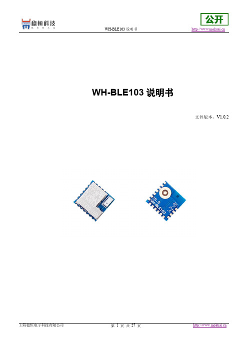
WH-BLE103说明书文件版本:V1.0.2产品特点●与USR-BLE101功能及封装相兼容,增加外置版本,增加GPIO●超小体积10x10x2mm●支持BLE4.2协议,向下兼容●平均310uA低功耗广播模式,平均500nA休眠模式,多种唤醒方式●支持主机和从机,快速切换●多种配置方式,串口AT指令,透传AT指令●支持1对多广播模式,内置iBeacon协议●蓝牙转UART数据传输● 2.1V~3.6V单电源供电●超远的传输距离,模块对传最大发射功率下可达60米●支持128bit格式UUID修改,可与其他厂家模块通信目录WH-BLE103说明书 (1)1.快速入门 (4)1.1.模块测试硬件环境 (4)1.2.数据传输测试 (5)2.产品概述 (8)2.1.产品简介 (8)2.2.模块基本参数 (8)2.3.硬件描述 (9)2.4.应用领域 (11)2.5.尺寸描述 (11)3.产品功能 (12)3.1.工作模式 (12)3.1.1.主设备模式 (12)3.1.2.从设备模式 (13)3.1.3.广播模式 (14)3.2.打包机制 (16)3.3.iBeacon协议 (17)3.4.低功耗模式 (19)3.5.密码配对验证 (20)3.6.数据传输加密 (20)3.7.断线重连 (21)3.8.指示灯状态 (21)3.9.AT指令配置 (22)3.9.1.串口AT指令 (22)3.9.2.透传AT指令 (23)3.9.3.AT指令概述 (23)3.10.AT指令集 (24)4.联系方式 (25)5.免责声明 (26)6.更新历史 (27)1.快速入门WH-BLE103模块是一款超低功耗蓝牙4.2模块,可用于点对点数据透明传输及加密传输,用户无需关心传输协议,只需要进行简单的设置就可以进行通讯。
本模块主从一体,用户既可以使用两个模块设置一主一从进行数据透传,还可以根据标准的BLE协议开发手机APP进行连接通讯。
FL1036资料
© Faraday Technology. As part of continual product improvement the specifications, details and dimensions shown in this publication are subject to change without noticeA new range of low cost luminance and chrominance anti-aliasing and reconstruction filters.The filters are designed for use in 4:2:2 a-d and d-a conversion i.e. sampling rates of 13.5 MHz (Y channel) and 6.75 MHz (U and V channels). Pre-filters have a flat passband and the post-filters are shaped to provide sinx/x correction. These filters provide similar performance to the Faraday TFT range but at much reduced cost.LUMINANCECHROMINANCEType NumberFL1035FL1038FL1036FL1039Filter Shape Lowpass Lowpass Lowpass Lowpass Passband Shape Flat Sinx/x Flat Sinx/x Sampling Frequency --13.5 MHz -- 6.75 MHz Insertion Loss at 100 kHz < 1.6 dB < 5.1 dB < 1.2 dB < 5.1 dB End Of Passband5.5 MHz 5.5 MHz 2.3 MHz 2.3 MHz Passband Amplitude Ripple 0.3 dB max 0.3 dB max 0.3 dB max 0.2 dB max Start Of Stopband 8.2 MHz 8.2 MHz 4.1 MHz 4.1 MHz Stopband Attenuation 40 dB 40 dB 40 dB 39.5 dB Group Delay Ripple < 21 ns < 23 ns < 42 ns < 48 ns Group Delay Bandwidth 5.0 MHz 5.0 MHz 2.3 MHz 2.3 MHz Delay Time at 200 kHz 220 ns + 5 ns 217 ns + 5 ns 450 ns + 5 ns 450 ns + 5 ns Impedance 75 ohms 75 ohms 75 ohms 75 ohms Temperature Range 0°C to 70°C 0°C to 70°C 0°C to 70°C 0°C to 70°C Aqueous Washable Yes Yes Yes Yes Package TypeDR00008BDR00008BDR00005ADR00008BMONITOR SPEC FILTERSLOW COSTPACKAGE DETAILFaraday Technology Ltd.Tel:+ 44 (0)1782 661501 Croft Road Industrial Estate,Fax:+ 44 (0)1782 630101 Newcastle, Staffordshire Email:sales@ ST5 0QZ. England.Web site:。
MAX1036-MAX1039资料
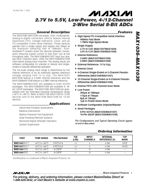
MAX1036–MAX1039
Applications
Hand-Held Portable Applications Medical Instruments Battery-Powered Test Equipment Solar-Powered Remote Systems Received-Signal-Strength Indicators System Supervision
Stresses beyond those listed under “Absolute Maximum Ratings” may cause permanent damage to the device. These are stress ratings only, and functional operation of the device at these or any other conditions beyond those indicated in the operational sections of the specifications is not implied. Exposure to absolute maximum rating conditions for extended periods may affect device reliability.
ELECTRICAL CHARACTERISTICS
(V DD = 2.7V to 3.6V (MAX1037/MAX1039), V DD = 4.5V to 5.5V (MAX1036/MAX1038). External reference, V REF = 2.048V (MAX1037/MAX1039), VREF = 4.096V (MAX1036/MAX1038). External clock, fSCL = 1.7MHz, TA = TMIN to TMAX, unless otherwise noted. Typical values are at TA = +25°C.)
FlexMove FC Series 传输系统产品目录说明书
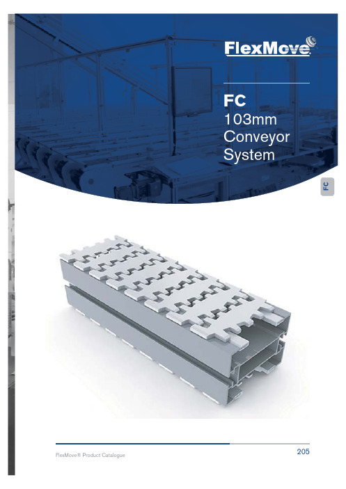
FC103mm Conveyor SystemCFFC SERIESFC Series CharacteristicBeam Width:105mmProduct Width: Refer to Guide Rail Assembly Accessories NeededSlide Rail Required: FASR-25 OR FASR-25U Slide Rail Colour: White Or Natural ColourSlide Rail Material: HDPE OR UHMW-PESlide Rail Rivet & Screw: FASLR-4X6 or FASLS-M5Connecting strip is used to connect 2 beams. Connecting Strip: FACS-25x140AUOM : 3 Meter / LengthUOM: pcFCSERIESChain Common DataPackaging: 5m per box Pitch: 35.5mm Width: 103mmTensile Strength at 20°C: 6000N Colour: White & Black (Conductive)Material :-Chain: White Acetal / POM Pivot: Polyamide Pivot Pin: Stainless SteelInsert (Wedge & Friction): TPE GreyExample for FCCT-5A17-L## = 1 cleated top chain with alternate of # link of plain chainThe above chain is FCCT-5A17-L1, 1 link cleated top chain with alternate of 1 link of plain chain.Note: # = 1, 2, 3, 4, 5 (20)UOM: 5 Meter / boxApplication: Suitable for horizontal and slope < 5° transport of products with accumulation.UOM: 5 Meter / boxApplication: Suitable for vertical transport of product with no accumulation.# = 1, 2, 3, 4, 5 (20)# = 1, 2, 3, 4, 5 (20)UOM: 5 Meter / boxApplication: Suitable for vertical transport of product with no accumulation.UOM: 5 Meter / boxApplication: Suitable for transport of static sensitive product...Cleat Top Chain FCCT-5A17-L#Cleat Top Chain FCCT-5A30-L#F CFC SERIESUOM: 5 Meter / boxApplication: Suitable for accumulation of product with low friction and pressure.UOM: 5 Meter / boxApplication: Suitable for vertical transportation of product in slope with no accumulation.UOM: 5 Meter / boxApplication: Suitable for vertical transportation of product in slope with no accumulation.Magnet Top Chain FCMT-5Magnet Top Chain FCMT-5-L#UOM: 5 Meter / boxApplication: Suitable for conveying of fer-romagnetic products in slope.UOM: 5 Meter / boxApplication: Suitable for conveying of fer-romagnetic products in slope.FCSERIESFCFT-5B Friction Top Chain FCFT-5CUOM: 5 Meter / boxApplication: Suitable for transport product in slope > 5 ° but ) 30 ° without accumulation.UOM: 5 Meter / boxApplication: Suitable for transport product in slope > 5 ° but ) 40 ° without accumulation.UOM: 5 Meter / boxApplication: Suitable for transport product in of slope > 5 ° but ) 30 ° without accumulation.UOM: 5 Meter / boxApplication: Suitable for transport product in of slope > 5 ° but ) 35 ° without accumulation.F CFCSERIESUOM: 5 Meter / boxApplication: (Safety Chain ) Suitable for ihorizontal and slope < 5 ° but ) 30 ° UOM: 5 Meter / boxApplication: (Safety Chain ) Suitable for ihorizontal and slope < 5 ° but ) 35 °FCSERIESSEW gear motors are products of SEW EurodriveFCSERIESFCFCSERIES SEW gear motors are products of SEW Eurodrive F CSERIESFCSEW gear motors are products of SEW Eurodrive F CSEW gear motors are products of SEW EurodriveSEW gear motors are products of SEW Eurodrive F CSEW gear motors are products of SEW EurodriveChain required 1-way : 0.6 meter Slide rail: 0 meter F CChain required 2-way : 1.3 meter Slide rail required 2-way: 2.8 meterChain required 2-way : 0.6 meter Slide rail required 2-way: 1.2 meterChain required 2-way : 0.5 meter Slide rail required 2-way: 1.0 meter F CUOM : pcHorizontal plain bend, 60° ± 1°CFIf an angle of 120° is needed for radius R500 horizontal plain227FlexMove® Product Catalogue FCSERIESFCFCSERIESFC Vertical Bend 30°FC Vertical Bend 45°FCVB-20R400FCWB-180R170AFCVB-45R400UOM : pcUOM : pcUOM : pcChain required 2-way: 0.6 meter Slide rail required 2-way: 1.2 meterChain required 2-way: 0.8 meter Slide rail required 2-way: 1.5 meterChain required 2-way: 1.0 meter Slide rail required 2-way: 1.9 meter228FlexMove reserves the right to make alteration without prior notification Every care has been taken to ensure the accuracy of theinformation contained in this catalogue but no liability can be accepted for any error or omissions.229FlexMove® Product Catalogue FCSERIESFC Vertical Bend 90°FC Vertical 5° - 90°FCVB-60R400FCVB-90R400UOM : pc UOM : pc Chain required 2-way: 1.2 meter Slide rail required 2-way: 2.4 meter Chain required 2-way: 1.6 meter Slide rail required 2-way: 3.2 meter Example for FC Vertical Bend Ordering - Vertical bend, Ø° ± 1°- FCVB-Ø°R400If an angle of 65° is needed for vertical bend, so the ordering part number isFCVB-65R400The outer bend is assembled using connecting strip (FACS-25x140A) .Angle of “Ø°” must be indicated when ordering.F C。
