KPF601G03中文资料
FLUXUS F G601和F G608肖像说明书

Portable, quick and reliable______FLUXUS® F/G601 and F/G608Portable ultrasonic clamp-on gas and liquid flow metersAccurate____Flexible____Quick____Rugged____ErgonomicExternal measurementof internal flow2FLUXUS ® F/G60X___Mobile flow measurement without compromisesThe benefits are evident...______J Unrivalled accuracy even at very low as well as high flow rates due to matched transducer pairs and innova-tive signal processing J Reliable measurement even in difficultconditions such as high solid contents or wet gas J High zero point stability and insensitivity in regard to pipe wall noise and wrong transducer positioning J Maximum flexibility for the measurement of virtually any liquid and gaseous media J Quick measurement; reliable results inno more than 5 minutesJ Rugged housing and ergonomic design optimized for daily usage in harshindustrial environments and hazardous areas J Long-life marathon battery;comprehensive energy management with display of remaining capacitysimply clamped onto the outside of the pipe and are never in direct contact with the medium flowing inside. No cutting into the pipe or process interruption is required for installation.FLUXUS ® offers maximum flexibility:J For virtually any pipe material andmedia, regardless of the conductivity and pressure level J Wide application range: two pairs of transducers are sufficient to cover the most common pipe diameters in industrial applicationsand FM certified). J Highly reliable measurements even at high solid contents or wet gas J Ideal measurement solution for the determination of a building‘s or plant‘s thermal energy consumption and total energy efficiency J Energy efficient battery management allowing for more than 17 hrs. of remote measurement12121011126123457891011126123457891011Measurement of Connection of12612345789101112612345789101112121011Input ofMounting of6Made for users by users___The features at a glanceRugged and ergonomic design______J compact and easy to handle______J carbon fibre reinforced housing andsteel armored cables designed for industrial usage ______J water and dust-tight; resistant againstoil, many liquids, and dirt ______J multi-functional carrying andset-up handle______J low weight______J QuickFix system for fast mountingin positions where a free hand for carrying is unavailable (e.g. for measurements at great heights)______J ATEX / IECEx and FM certified forusage in hazardous areas ______Highly accurate and reliable______J extensive media database of liquidsand gases______J proven FLUXUS ® electronics, sophi-sticated transducer matching and automatic compensation of changing ambient temperatures (according to ANSI/ASME MFC 5.1-2011 recom-mendations) assures an unrivalled zero point stability and no measure-ment drift ______J calibration of transducers andtransmitters (traceable to nationalstandards)______J high operational safety in case ofmedia with a high percentage of gas and solids or wet gas ______J high accuracy even in non-idealconditions due to innovative signal processing algorithms, e.g. for the correction of pipe wall echoes and transducer positioning errors7Cutting edge functionalities______J integrated measurement of the pipewall thickness______J automatic loading of calibration dataand transducer identificationprevents parameterisation errors, speeds up the set-up and ensures a precise measurement ______J portable thermal energy measure-ment (ideal for energy audits, opti-misation of heating systems, energyconsumption measurements, etc.) ______Easy operation______J fast set-up due to automatic loadingof transducer data ______J intuitive user interface______J high-contrast, easy-to-read displaywith backlight ______Excellent battery management______J precise display of remaining capacity______J more than 17 hours of remote mea-surement with lithium-ion batteries ______J no self-discharge, no memory effect______Sturdy case______J extremely sturdy case; may evenbe used as a step ______J intuitive stowing and finding of allcomponents ______J watertight (IP67)______J offers protection in humid and dirtyenvironments ______Focusing on energy efficiency___Portable thermal energy and compressed air measurementBalancing energy usage is usually of traceable energy management system.Highly flexible and multifunctional, thesemeasurement solutions can be used forthe temporary measurement of ratherhuge thermal energy streams in district000000010The portable FLUXUS ® flow meters are available in various, application tailored, versions:FLUXUS ® F601 as the standard portable flow meter for measurement at liquid filled pipes, with the option Energy and Multifunctional for thermal energy measurements.FLUXUS ® G601 for the flow measurement at gas filled pipes and as combined measurement device, FLUXUS ® G601 CA Energy , for the flow measurement of liquids and gases as well as thermal energy quantification and compressed air balancing.As FLUXUS ® F608, G608 and G608 CA Energy , the portable liquid and gas flow meters are also applicable for usage in hazardous areas (ATEX, IECEx and FM certified).Our application engineers will be happy to assist you for a precise adaptation of the measuring system to your requirements.* under reference conditions and with v > 0.15 m/s; ** if reference uncertainty better than 0.2 %General technical specificationsF608: -G608: -Standard Version: Outputs:F601: 2 x current, 2 x binary F608: 2 x current, 2 x binary G601: 2 (1) x current, 2 x binary, (1 x freq.) G608: 2 x current, 2 x binaryEnergy Version: Inputs:F601: 2 (4) x temp.F608: 2 (4) x temp.G601 CA Energy: 2 x temp., 2 x currentG608: 2 x temp.; (G608 CA Energy: 4 x temp.)Energy Version: Outputs:F601: 2 x current, 2 x binary F608: 2 x current, 2 x binary G601 CA Energy: 2 x current, 2 x binary; G608 (CA Energy): 2 x current, 2 x binary Multifunctional Version: Inputs:F601: 2 x temp., 2 x current G601: 2 x current, 2 x binary, 1 x freq.Multifunctional Version: Outputs:F601: 4 x current, 2 x binary G601: 1 x temp., 2 x current, 1 x voltage11Power adapter / charging unitCoupling compound Wall thickness probeFlow transducersFLUXUS ® F/G60XtransmitterSoftware FluxData, RS232 cable and USB adapterManual andquick-start guideMeasuring tapeMounting fixture for the transducersQuickFix mounting system for the transmitterThe complete measuring system and the required accessories fit into a sturdy protective transport case.The case‘s dimensions are in accordan-ce with airline requirements for carry- on luggage.Please see the price lists for details on the scope of delivery and the accessories. Special accessories are possible. Our application engineers will be pleased to advise you.FLEXIM ______。
空预器变频说明书

CBK型空气预热器传动变频控制系统使用说明书航天科工哈尔滨风华有限公司电站设备分公司目 录1 主要用途与适用范围 (1)2 系统组成与功能 (1)3 主要技术参数 (2)4 工作原理 (2)5 安装 (3)6 使用与操作 (5)7 维护与保养 (6)检修空预器时,必须将柜内"运行投入和运行抑制"旋钮切到"运行抑制"。
检测电机绝缘时,必须全部脱开电机与变频器之间的导线。
1 主要用途与适用范围空气预热器传动变频控制系统是应用变频器对空气预热器的传动进行软启动的控制设备。
它具有启动力矩大、设备冲击小、运行可靠、结构简单等优点,是针对空气预热器这类大惯性负载较为理想的控制系统。
空气预热器传动变频控制系统适用于65MW、135MW、300MW、600MW、1000MW等火电机组空气预热器的配套。
2 系统组成与功能2.1 系统组成空气预热器传动变频控制系统包括控制柜2台(A、B侧各1台),每台控制柜中配置主、辅两台变频器分别对主、辅电机进行控制;每台控制柜配置1台制动控制箱,用以进行过压保护。
系统同时包括转子停转检测装置2套(A、B侧各1套),每套配置3个探头及作用板,对转子停转进行监测。
(图1:单侧系统构成示意图)图1:单侧系统构成示意图2.2 系统功能a) 具有高速、低速、调试档,以满足设备运行的不同需要。
b) 具有主、辅电机之间自动切换的功能,当主电机出现变频器故障,电机卡死等故障时,可以自动切换为辅电机运行,反之亦可。
c) 系统具有远方控制和就地操作两种途径,在控制柜内设有切换开关。
d) 系统可以分别给出每台变频器DC 4~20mA的电机运行电流信号。
e) 当变频器故障、电源故障、转子停转时,发出报警信号。
3 主要技术参数a) 主、辅变频器功率:≥7.5kWb) 供电电源:AC 380V 50Hz 三相四线 两路(厂用、保安)c) 输出继电器负载能力:5A /AC 240V 5A /DC 28Vd) 环境温度:-10℃~50℃e) 相对湿度:<85%4 工作原理系统(单侧、以下同)采用两台变频器分别驱动主、辅电机,可使主、辅电机分别具有高速、低速两档驱动电机功能,其中高速档为正常工作档,低速档为清洗空预器时使用。
国泰怡安产品优势简介

G6系统特性
气体灭火控制器比较
公司 型号 每区线数 独立工作
海湾消防 海湾消防
QKP06 QKP-04/02 FS5090 JB-QB-QM200/4 EI-6000QT GK652 GK652B
11 4+4 14 18 14+2 7+4 4+4
与控制器配合 可以
壁挂/柜式 壁挂(新国标)
利达华信
3
G6系统特性
G6产品优势
• 但是由于二极管存在寄生电容,信号输出后会引 起畸变;线路好的情况可能无影响,但线路长时 或线路状况不好时,信号畸变的厉害,影响了总 线的稳定性;所以国外厂商都不采用这种方式, 抗干扰性、稳定性都不如有极性的;
回路线1
1
D? 4
2
输入波形
回路线2
3
输出波形
2009年4月20日
G6系统特性
国泰怡安产品优势简介
2009年4月20日
G6系统特性
G6系列控制器 型号 GK601H GK603 GK603G GK614 GK652
安装方式
最大容量 10200点 510 510 119+8 127
RS485
252个设备 126个设备 126个设备
备注
含6路联动 含6路联动 含1路联动 最多含4区气 体灭火控制
G6系统特性
探测器特性
• 采用美国Microchip公司的MCU,功能强、 可靠性高; • 内嵌智能算法、自动比对燃烧曲线,可探 测4种火产生的烟雾; • 对环境因素自动补偿; • 360度可见灯; • 亮灯巡检和灭灯巡检可设置;
2009年4月20日
G6系统特性
控制模块特性
• 真正的两总线结构,与控制器只需两线连接; • 可监视模块至受控设备间连线的断线、短路;及时发现设 备问题; • 采用美国Microchip公司的MCU,功能强、可靠性高;
G601
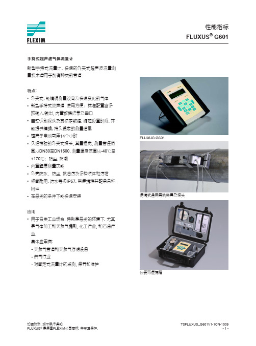
TSFLUXUS_G601V1-1CN-1009 --
如有改动�, 恕不另行通知. FLUXUS® 是德国FLEXIM公司商标, 并受其保护.
性能指标
FLUXUS 通讯 接口 软件 软件操作系统 (所有WindowsTM版本) 电缆 接头 输出
组数 配件
standard version • 能Au提to供ma精ti确c l,o持ad久ing稳o定f c的al测ibr量at结ion果data and transducer • 锂de离te子cti电on池, r可ed用uc1e4s个se小t-时up times and provides
precise, long-term stable results •• 久Li-经Io考n b验at的te外ry夹fo式r 1探4 头ho,u其rs量of程m宽ea,s测ur量em管e径nt范operation
0.01...1000 units 1...1000 ms
输t; 2)
温度输入
Pt100/ Pt1000 4线 -150...+560 ℃ 0.01 K ±0.01%读数±0.03 K
电流输入
无源: -20...+20 mA 0.1%读数±10μA Ri =50Ω, Pi < 0.3 W
范围 精度 有源输出 无源输出
范围 集电极开路
自动继电器 作为报警输出 作为脉冲输出 -脉冲值 -脉冲宽度
输入
组数 配件
类型 连接 范围 分辨率 精度
范围 精度 无源输入
范围 精度 内阻
G601
RS232/USB
FluxData: 下载测量值/记录, 图形显示, 格式转换(例如: ExcelTM ) FluxKoeff: 生成被测介质参数 RS232 RS232 – USB
重庆高压可控硅模块型号

重庆高压可控硅模块型号
随着电子技术的不断发展,高压可控硅模块在电力、工业控制等领域得到了广泛应用。
在重庆地区,也有多种型号的高压可控硅模块供应。
以下是一些常见的重庆高压可控硅模块型号:
1. KP1000A-380V:额定电压380V,额定电流1000A,最大阻断电压2000V。
2. KS500A-220V:额定电压220V,额定电流500A,最大阻断电压1200V。
3. ST2400A-400V:额定电压400V,额定电流2400A,最大阻断电压2500V。
4. KF2000A-220V:额定电压220V,额定电流2000A,最大阻断电压1800V。
以上是一些常见的重庆高压可控硅模块型号,不同型号的模块有不同的应用场景和技术参数,用户可根据具体需求进行选择。
- 1 -。
调压阀
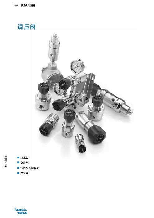
6000
(413)
✓ ✓ ✓ ✓ ✓ ✓
✓ ✓ ✓ ✓ ✓
✓ ✓ ✓ ✓ ✓
✓ ✓ ✓ ✓ ✓
✓ ✓ ✓ ✓ ✓
✓ ✓
3600
(248)
✓
6000
(413)
10 000
(689)
✓ ✓ ✓ ✓ ✓ ✓ ✓ ✓ ✓ ✓ ✓ ✓ ✓ ✓ ✓ ✓ ✓ ✓ ✓ ✓ ✓ ✓ ✓ ✓ ✓ ✓ ✓ ✓ ✓ ✓ ✓ ✓
世伟洛克调压阀不是压力设备指令 97/23/EC 中定义的
“安全附件”。
请勿将调压阀用作关闭装置。 自排放调压阀和捕获排放调压阀能够把系统流体释放到大 气。 请注意将自排放孔或捕获排放连接口远离操作人员。 更 多的信息, 请参考第 2 页上的排放选购件。
氧气服务危险性
如要获得更多有关富氧系统危险性的信息, 见世伟洛克氧气 系统安全 技术报告 (MS-06-13C4), P 852。
(3.5 至 413) (6.8 至 689)
流量系数 (Cv) 0.02 0.06 0.10 0.20 0.25 0.50 1.0 页号 673 675 677
减压型
✓
✓ ✓
✓ ✓ ✓
✓ ✓ ✓ ✓
✓
✓
679 681 683
✓ ✓ ✓
✓ ✓ ✓ ✓ ✓ ✓ ✓ ✓ ✓ ✓ ✓ ✓ ✓ ✓ ✓ ✓
特种调压阀
减压调压阀, 708 中高压 (KPP 系列), 683
670
调压阀/过滤器
调压阀的操作
调压阀可以把从钢瓶, 压缩机等来源排出的气体或液体的压力降低到分析仪等设备所需的较低值。 当进口压力与控制范围 压力与液体处理系统的压力要求十分接近时, 调压阀的分辨率和控制能力较高。 分辨率指把调压阀从最低出口压力设置调 整到最高出口压力设置所需的手柄转动周数。 控制能力指调压阀保持给定出口压力设定点的能力。
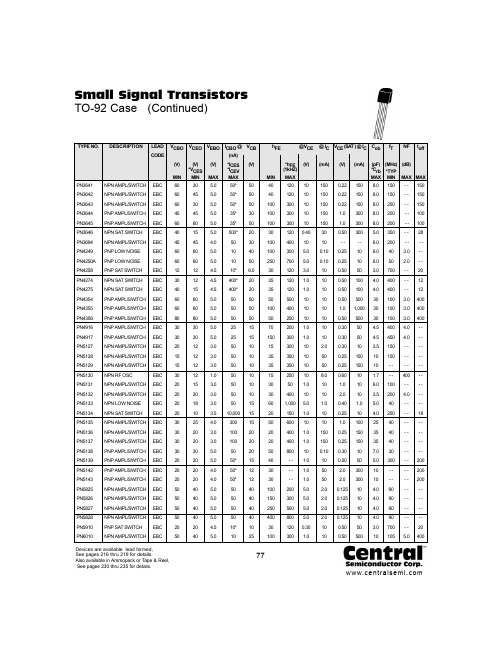
PN6010中文资料
60 60 60 45 60 40 45 60 60 12 30 40 60 60 80 30 30 20 15 15 30 20 20 20 20 30 30 30 30 20 20 20 50 50 50 50 20 50
10 10 10 10 10 0.40 10 5.0 5.0 3.0 1.0 1.0 10 10 10 1.0 1.0 10 10 10 10 1.0 10 5.0 1.0 10 1.0 1.0 10 1.0 1.0 1.0 5.0 5.0 5.0 5.0 0.30 1.0
150 150 150 150 150 30 10 0.10 0.10 10 10 10 10 10 10 10 10 2.0 50 50 8.0 10 10 1.0 10 10 150 150 0.10 10 50 50 2.0 2.0 2.0 2.0 10 10
0.22 0.22 0.22 1.0 1.0 0.50 -0.25 0.25 0.50 0.50 0.50 0.50 1.0 0.50 0.30 0.30 0.30 0.25 0.25 0.60 1.0 2.0 0.40 0.25 1.0 0.25 0.25 0.30 0.50 2.0 2.0 0.125 0.125 0.125 0.125 0.50 0.50
PN3641 PN3642 PN3643 PN3644 PN3645 PN3646 PN3694 PN4249 PN4250A PN4258 PN4274 PN4275 PN4354 PN4355 PN4356 PN4916 PN4917 PN5127 PN5128 PN5129 PN5130 PN5131 PN5132 PN5133 PN5134 PN5135 PN5136 PN5137 PN5138 PN5139 PN5142 PN5143 PN5825 PN5826 PN5827 PN5828 PN5910 PN6010
Fisher ACF6010说明书
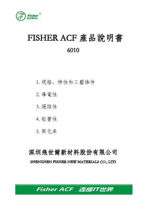
圖 3-1
在上述邦定條件下,初始和老化試驗後的絕緣阻抗≥108Ω,試驗結果表明 6010 絕緣阻抗足夠大,絕緣性能優良。
4. 粘著性
4.1 剝離強度與邦定溫度的相關性(圖 4-1)
測試材料:FPC:PI,75μm;Cu:36μm;Sn 鍍層;pitch:100μm
玻璃:ITO 全部電極;ACF6010 寬 1.5mm, 压头宽度2mm
4
3. 絕緣性
圖 2-1
圖 2-2
測試材料:专用绝缘模块电路;ITO 玻璃:t=1.1mm; ACF6010,宽度 2.5mm 測試設備:高阻計(PC68 型數字高阻計) 測試方法:在 23℃ 和 65%RH 的條件下, 50V DC、60s 測定樣品絕緣阻抗。 邦定條件:180℃,2MPa,13s 高溫高濕(85℃,85%RH)進行可靠性測試(圖 3-1):
項目
最小連
Pitch
接電路 Bump space
標
厚度
准
寬度 長度
規
顏色
盤心直徑
格 導電粒子
粒徑 密度
單位 μm μm μm mm m —— mm μm
粒數/ mm2
6010 100 50 25 1.0,1.2,1.5,2.0,3.0 50,100 灰色 25.4 10
0.8k
備注 Polymer/Ni/Au
測試設備:數字萬用表(ADVAN TEST R6441B)
測試方法:四探針法
邦定條件:180℃,2MPa,13s
2
2.1 高溫高濕(85℃,85%RH)試驗對接點阻抗的影響(圖 2-1) 2.2 冷熱衝擊(-40℃/100℃)試驗對接點阻抗的影響(圖 2-2)
(-40℃,30min;室溫,5min;100℃,30min)
新风光变频器说明书

新风光变频器说明书LT风光低压变频器说明书山东新风光电子科技发展有限公司关于本说明书的说明说明1. 本说明书是为380V-660V级通用变频器编写的,对专用变频器和中、高压变频器还另有专用说明书。
其不同型号的变频器主要差别在于软件。
由于主接线端子排、显示屏和键盘完全一样,所以电源接线、使用方法、维护要求等也几乎完全一样。
2. 由于产品更新迅速,本说明书内容如有更改,恕不另行通知。
资料已经仔细核对,力求准确无误,如有印刷错漏,敬请原谅。
3. 若对本说明书有不明之处,欢迎咨询。
山东新风光电子科技发展有限公司地址:济南市泺源大街玉泉森信大厦B座邮编:250063电话:0531-******** 85108679 传真:0531-85108681E-mial:info@中文域名:WWW.高压变频器.cn制造基地:山东省汶上县城广场路西段769号邮编:272500前言欢迎选购JD-BP系列变频器。
山东新风光电子科技发展有限公司是变频器专业制造商,中国电器工业协会变频器分会副理事长单位,变频器国家标准的起草审定单位,国内最早研制变频器的公司之一,山东省高新技术企业,开发制造变频器的技术处于国内领先水平,可为用户量身定做各种型号的变频器。
JD-BP系列高性能全数字化电动机变频调速器以第三代IGBT和第四代IPM为大功率开关器件,以先进的16位专用微处理器为控制部件,构成了一个完整的开环或闭环调控系统。
该设备性能优良、功能齐全、可靠性高、操作尤为简便。
使用该设备可以实现交流电动机大范围内的无级平滑调速,在运行过程中能随时检测电动机的负载情况,自动调整功率输出,使电动机始终处在最佳运行状态,在整个调速范围内均有很高的效率,节能效果明显。
为使操作正确无误,以利充分发挥其强大功能,请在使用前务必仔细阅读本说明书,并请妥善保存,以便日后查阅。
对于使用非本公司规定的环境与要求条件时,请事先与我公司联系。
第一章序言本公司的品牌商标为,产品型号为JD-BP系列,现以三相、380V、500KW 风机用变频器为例来说明型号的命名规则:1.1品牌及型号说明JD-BP32-500F异步电动机变频器系列输入电压相数,1或3输入电压等级1—2202—3803---6604---1145---2306---300适用电机功率(KW)用途分类风机水泵类为F提升机类为T机械类为J高频类为H专用类为Z派生类为P1.2产品体系我公司生产的变频器品种多、规格全,为了便于您的选择现按类别介绍一下:按电压等级分类:低压-----220V、380V、660V中压-----750V以上,6000V以下高压-----6000V至10000V按结构分类:壁挂式、台式、柜式(三种结构由容量大小决定)按用途分类:风机、水泵类负载-----节能最为明显 ,在型号系列中以F标识;重物提升类负载-------如矿井提升机,要求起动力矩大、低速力矩大、制动力矩大、四象限运行, 在型号系列中以 T 标识;机械控制类负载-------如化工机械、纺织机械、建筑机械、空压机、搅拌机、传送带等等,不但节能,而且能提高产品质量、提高生产效率, 在型号系列中以 J 标识;高频类负载------- 频率大于60Hz,如磨床用, 在型号系列中以 G 标识;专用类-------- 如直线电机用、油田潜油电泵用,在型号系列中以 Z 标识;派生类产品------- 如中频电源,能大范围调压、调频,对输入电源而言又能稳压稳频。
科沃600变频器说明书
手动设定:额定输出的0.0~20.0%; 自动转矩提升
直流制动
直流制动频率0.0~10.0Hz 制动时间0~20.0S
加减速方式
直流,曲线可选,四种加减速时间
PLC行及多段速运行 通过内置PLC或控制端子可实现15段速运行
内 置P I D
可方便实现压力,流量,温度等的闭环控制
共直流母线
多台变频器共用直流母线,能量自动均衡
若选用电机与变频器额定容量不匹配时,特别是变频器额定功率大于电机额定功 率时,务必调整变频器内电机保护相关参数值或在电机前加热继电器对电机保护。 三、工频以上运行
本变频器可提供0~600Hz的输出频率,若客户需在50Hz以上运行时,请考虑机械装 置的承受力。 四、关于电动机发热及噪声
因变频器输出电压是PWM波,含有一定的谐波,因此电机的温升、噪声和振动同 工频运行相比会有增加。 五、输出侧有压敏器件或改善功率因数的电容的情况
★ 不能让导线或螺钉掉入变频器中,否则引起变频器损坏!
三、配线时:
危险
★ 应由专业电气工程人员施工,否则有触电危险! ★ 变频器和电源之间必须有断路器隔开,否则可能发生火警! ★ 接线前请确认电源处于关断状态,否则有触电危险! ★ 请按标准要求接地,否则有触电危险!
第1页
K V F 6 0 0系 列
本系列变频器内装有雷击过电流保护装置,对于感应雷有一定的自我保护能力, 对于雷电频发处客户还应在变频器前端加装保护。 十、海拔高度与降额使用
在海拔高度超过1000米的地区,由于空气稀薄造成变频器的散热效果变差,有必 要 降 额 使 用,此 情 况 请 向 我 公 司 进 行 技 术 咨 询 。 十一、一些特殊用法
伤害或设备损坏!
第3页
关节轴承K系列
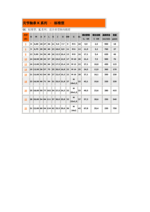
GI Standard, series K especially suited for axial loadsGI,标准型,K系列,适合承受轴向载荷GA Standard, series K especially suited for axial loadsGA,标准型,K系列,适合承受轴向载荷GIS Heavy duty, series K especially suited for high speed applicationsGIS,重载型,K系列,适合高速应用GAS Heavy duty, series K especially suited for high speed applicationsGAS,重载型,K系列,适合高速应用GIXS Heavy duty, series K especially suited for high pressure and tension loadsGIXS,重载型,K系列,适合高压力和高张力载荷GAXS Heavy duty, series K especially suited for high pressure and tension loadsGAXS,重载型,K系列,适合高压和张力载荷GIRS Stainless steel, series K for use in corrosive environmentsGIRS,不锈钢型,K系列,用于腐蚀环境GARS Stainless steel, series K for use in corrosive environmentsGARS,不锈钢型,K系列,用于腐蚀环境GISW maintenance free, series K for use at lower revs and dynamic loadsGISW,免维护型,K系列,用于低转和动载GASW maintenance free, series K for use at lower revs and dynamic loadsGASW,免维护型,K系列,用于低转和动载GIXSW maintenance free, series K for use at lower revs and high pressure and tension loads GIXSW,免维护型,K系列,用于低转和高压及张力载荷GAXSW maintenance free, series K for use at lower revs and high pressure and tension loads GAXSW,免维护型,K系列,用于低转和高压及张力载荷GIOW maintenance free, series K for use in applications involving minimum axial loads and limited oscillating movementsGIOW,免维护型,K系列,用于包含最小轴向载荷和有限振荡运动GAOW maintenance free, series K for use in applications involving minimum axial loads and limited oscillating movementsGAOW,免维护型,K系列,用于包含最小轴向载荷和有限振荡运动EI..D maintenance free, series E for use in applications involving minimum axial loads and limited oscillating movements (narrow head)EI..D,免维护型,E系列(窄头型),用于包含最小轴向载荷和有限振荡运动EA..D maintenance free, series E for use in applications involving minimum axial loads and limited oscillating movements (narrow head)EA..D,免维护型,E系列(窄头型),用于包含最小轴向载荷和有限振荡运动GIRSW stainless steel and maintenance free, series K for use at lower revs and high pressure and tension loads in corrosive environmentsGIRSW,不锈钢及免维护型,K系列,用于腐蚀环境下低速和高压及张力载荷GARSW stainless steel and maintenance free, series K for use at lower revs and high pressure and tension loads in corrosive environmentsGARSW,不锈钢及免维护型,K系列,用于腐蚀环境下低速和高压及张力载荷EI..D-NIRO stainless steel and maintenance free, series E for use at lower revs and high pressure and tension loads in corrosive environments (narrow head)EI..D-NIRO,不锈钢及免维护型,E系列(窄头型),用于腐蚀环境下低速和高压及张力载荷EA..D-NIRO stainless steel and maintenance free, series E for use at lower revs and high pressure and tension loads in corrosive environments (narrow head)EA..D-NIRO,不锈钢及免维护型,E系列(窄头型),用于腐蚀环境下低速和高压及张力载荷GIO steel on steel, series K high axial loads in one direction only. To be used only with limited oscillating movementsGIO 钢型,K系列,仅单向高轴向载荷。
晶闸管型号

国产晶闸管的型号命名方法
国产晶闸管的型号命名(JB1144-75部颁发标准)主要由四部分组成,
各部分的含义见下表。
第一部分用字母“K”表示主称为晶闸管。
第二部分用字母表示晶闸管的类别。
第三部分用数字表示晶闸管的额定通态电流值。
第四部分用数字表示重复峰值电压级数。
例如:
国产电子管的型号命名由部分组成,各部分的含义见下表。
第一部分用数字表示灯丝电压值。
第二部分用字母表示电子管的类型(结构与用途)。
第三部分用数字表示电子管的序号及性能。
第四部分用字母表示电子管的材料和外形。
交流侧过电压,过电流的保护设计。
双回路煤矿风机用隔爆型双电源真空电磁起动器使用说明书1(1)

实用标准文案尊敬的金科星用户:感谢您选择、使用金科星产品。
金科星产品质量优,性能佳。
为了方便您使用,请您详细阅读说明书,并按照说明书的步骤操作。
自始至终金科星的优质服务将伴随着您,使用时无论有什么问题,请按照说明书上的电话、地址联系,我们时刻恭候为您服务。
金科星---靠品质取胜!由于产品的升级,改进。
您所购买的金科星产品可能与说明书中介绍不完全一致。
请多关注!文档该系列产品执行企业标准执行标准编号:Q/ZJZ111-2009安标编号:MAD060054目录敬告用户 (2)概述 (3)用途和使用范围 (3)使用条件 (4)基本参数 (5)结构 (8)1工作原理 (10)使用与维护 (13)注意事项 (14)常见故障分析排除表 (14)运输及贮存 (15)订货须知 (16)售后服务 (16)敬告用户:为更好的售后服务优质化,我公司专门制定了金科星用户2指导安装维修卡,请您务必配合我们在“服务单位意见”一栏里填写您们的意见后,交给专门售服人员。
如果你感到服务不满意,可拒绝在安装、维修卡上签字,并向我公司反映,我公司会及时进行处理,保证您的满意。
附:金科星用户指导安装、维修卡3服务单位联系人电话产品名称购货日期保修期内□保修期外□产品型号产品编号指导安装□故障现象处理结果服务单位意见分管领导意见售服人员工作起止时间4一、概述QBZ3-80/660(380)SF煤矿风机用隔爆型双电源真空电磁起动器(以下简称起动器),具有主启动器手动起动、主启动器出现故障时备用启动器自动起动;可使用于要求双回路、双电源不间断运行的局部扇风机、井下排水泵和气体抽样分析机的控制设备。
实现对掘进巷道进行不间断供风、排水、抽气的功能。
可用于煤矿井下具有瓦斯、煤尘爆炸危险的场合。
特别能可靠的对掘进工作面进行不间断通风控制,符合国家安全监察局2005年颁布实施的《煤矿安全规程》规定。
投资少、维修使用方便,保护性能齐全,运行安全可靠,可节省启动器的台数和多处电源接头,节约设备投资,并减少事故点,提高了工作效率,是目前掘进工作面理想的双电源双回路局部扇风机控制用起动器。
泰安众诚移变开关高压说明书

|
矿用开关
4、使用环境条件
(1)海拔高度不超过 2000m;
(2)周围环境温度为-5℃~+40℃;
(3)周围空气相对湿度不大于 95% (25℃时);
(4)具有瓦斯和煤尘爆炸危险的煤矿井下;
(5)在无破坏金属和绝缘的腐蚀性气体及蒸汽的环境中;
(6)在无强烈颠簸和冲击振动的环境中;
(7)在能防滴水和无水浸的环境中;
KB || || || || || |
G- | | | |
/6Y | || || |
移动变电站用 额定电压(kV) 电流设定(50- A) 高压 隔爆型 矿用开关
K B G - 315 / 10
|| | || | || |
|| || |
额定电压(kV) 额定电流(50-315A)
|| |
高压
||
隔爆型
产品简介
该 产 品 系 全 国 首 台 采 用 进 口 工 业 可 编 程 序 控 制 器 ( PLC ) 和 人 机 屏 (GOT)的矿用隔爆型高压真空开关,具有独立的高压隔离开关腔,配套移动变 电站采用国际流行的低压侧故障分断高压侧电源的运行模式。该产品既吸纳了国 际先进的智能化技术和结构型式,又有机地结合了中国煤矿配套电气设备的特 性,可与进口变压器和国产变压器配套使用。同时该产品符合 GB3836-2000〈〈爆 炸性环境防爆电气设备〉〉最新国家标准规定,其技术指标、性能和结构等各方 面均优于国内同类产品,为我国煤矿井下提供了一种性能优良、安全可靠的电气 设备,是广大客户同类产品的最佳选择。
-
-
10kV 额定短时工频
Generated by Foxit PDF Creator © Foxit Software For evaluation only.
- 1、下载文档前请自行甄别文档内容的完整性,平台不提供额外的编辑、内容补充、找答案等附加服务。
- 2、"仅部分预览"的文档,不可在线预览部分如存在完整性等问题,可反馈申请退款(可完整预览的文档不适用该条件!)。
- 3、如文档侵犯您的权益,请联系客服反馈,我们会尽快为您处理(人工客服工作时间:9:00-18:30)。
PSM1FEATURESBroad Pressure Range : 50~1,000kPa.High Sensitivity, Excellent Linearity.Highly Stable in Temperature Change.APPLICATIONSMedical Deivces.Industrial Instrumentations.Pressure Switch, Water Height Control, Pneumatic Devices etc.Home Appliances.MAXIMUM RATINGMODEL NUMBER FOR ORDERINGUNIT Operating Input Current 1.5constant, Ambient Temperature Ta=25mV 20mV 0.30.525.02.5kgf/kPa kPa(kgf/)-5.0TCO(%FS)TCS(%FS)2550-4.01.04.05.02.03.0-3.0-2.0-1.0Temperature ( C)Operating Input Current : 1.5mA, Spec. : 5.0 %FS2. Temperature Coefficient of Offset (TCO)+_-20Rated Pressure (kPa)FullScaleVoltage(mV)1/2Pr Pr204060120801001. Full Scale Voltage CharacteristicsOperating Input Current : 1.5mA, Temperature : 25 C-2.502550-2.00.52.02.51.01.5-1.5-1.0-0.5Temperature ( C)3. Temperature Coefficient of Sensitivity (TCS)Operating Input Current : 1.5mA, Spec. : 2.5%FS+_-3Pressure CycleOffsetVoltageVariation(%FS)Offset Voltage Variation500,0001,000,000-2-1312-3Pressure CycleFullScaleVoltageVariation(%FS)Full Scale Voltage Variation500,0001,000,000-2-13124. High Temperature continuous Operating Test100°C, 1 million times : After testing, offset and full scale voltage variation is very small.CHARACTERISTIC GRAPHSRELIABILITY TEST120, 1000hrs-40, 1000hrs255, 1 million times, Rated Pressure-20, 1 million times, Rated Pressure100, 1 million times, Rated Pressure40, 90%RH, 1 million times, Rated Voltage260, 10 seconds-40~120, 30minutes/1Cycle, 100CyclesAmplitude : 1.5mm, Frequency : 10~55Hz,X, Y, Z(3-directions), 2 hrs each direction75cm height, 2 timesBending Strength : 4.9N(0.5kgf), Right/Left 90, 1time230, 5 seconds0.25current source1Terminal No.Meaning 23456(+)Input Open(-)Output (+)Output (-)Input (-)InputPACKAGE DIMENSIONS AND PC BOARD PATTERN (Unit :mm)PIN CONFIGURATIONNote1. Mounting on printed circuit boardsWhen mounting a transistor on a printed circuit, it is assumed that lead wires will be processed or reformed due to space limitation or relations with other components. Even if no such special processing reforming is conducted exercise care on the following points :(a) Make the spaces of lead wire inserting holes on the printed circuit board the same as those of lead wires on a transistor.(b) Even if The spaces are not the same, do not pull the lead wires or push heavily against the sensor element.(c) Use a spacer for form a lead maintain space between a sensor and a printed circuit board, rather than closely contacting them with each other.(d) When forming a lead prior to mounting onto a board- Bend the lead at a point 3mm or more apart from the body(Lead root).- Bend one lead wire after securing the other lead wire. (near the main body)- Keep space between the sensor main body and and a fixing jig.- When bending the lead along the jig, be careful not to damage it with an edge of the jig.- Follow other precautions described in respective standard (e) When mounting a sensor onto a heat sink - Use the specified accessory.- Drill threaded holes on the heat kink as per specifications and keep the surface free from burrs and undulations.- Use KEC’s recommended silicon grease.- Tighten the screw within the specified torque.- Never apply a pneumatic screwdriver to a transistor main body.(f) Do not bend or stretch the lead wires repeatedly.When pulling in the axial directions, apply 500g or 600gpower, depending on the shapes of lead wires.2. SolderingWhen soldering a sensor to a printed circuit board, the soldering temperature is usually so high that it adversely affects the sensor.Normally, tests are conducted at a soldering temperature of 265for 10 seconds or 300for 3 seconds. Be sure to complete soldering procedures under these conditions of temperature and time.Be careful to select a type of flux that will neither corrode thelead wires nor affect the electrical characteristics of a sensor.The basic precautions for soldering procedures are as follows :(a) Complete soldering procedures in a time as short as possible.(b) Do not apply stress to a sensor after soldering by correcting or modifying its location or direction.(c) For a sensor employing a heat sink, mount it on the heat sink first: then solder this unit to a printed circuit board after confirming that it is fully secured.(d) Do not directly solder the heat-radiating portion of a sensor to a printed circuit board.(e) In flow solder jobs, sensors are apt to float on the solder due to solder surface tension. When adjusting the locations of sensor, be careful not to apply excessive stress to the roots of the sensor lead wires.(f) When using a soldering iron select those which have less leakage, and be sure to ground the soldering iron.3. Cleaning a circuit boardAfter soldering, circuit boards must be cleaned to remove flux.Observe the following precautions while cleaning them(a) When cleaning circuit boards to remove flux, make sure that no residual reactive ions such as Na or Cl ions remain. Note that organic solvents react with water to generate hydrogen chloride and other corrosive gases which can degrade device performance.(b) Do not rub the indication marks with a brush or one ’s fingers when cleaning or while a cleaning agent is applied to the markings.(c) There are ultrasonic wave cleaning methods which offer a high cleaning effect within a short time. Since there methods involve a complicated combination of factors such as the cleaning bath size, ultrasonic wave vibrator output, and printed circuit board mounting method, there is fear that the service life of airtight seal-type sensors may be extremelyshortened. Therefore, as far as possible avoid using the ultrasonic wave cleaning method.- Basic requirements of ultrasonic wave cleaning method.Frequency : 27~29kHzOutput : 300W or less (300W/or less)Recommended solvents : Refer to details above Cleaning time : 30seconds or lessThe Pressure sensor is designed to convert a voltage by means of constant current drive and then, if nesessary, it amplifies the voltage for use. The circuit shown below is a typical example of a。
