用于多程放大系统光束反转器的等离子体电极电光开关
光纤通信光开关原理
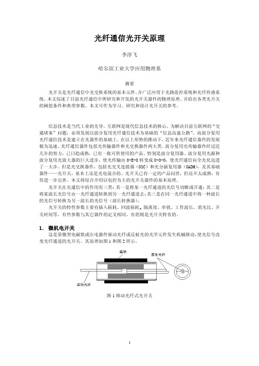
表 2 两种电光开关的指标 材料 InP/InGaAsP 有机聚合物 插损 dB 5dB 1dB 消光比 dB 15dB >20dB 偏振灵敏度 dB 0.5dB 0.5dB 开启时间 ns 0.2 0.1
但由于半导体载流子复合时间的限制,开关时间一般要在 10ns 以上。与机械光开关相比, 其主要优点除开关速度高之外,因为没有移动部件,重复率较高,寿命较长。 电光开关一般利用 Pockels 效应,也就是折射率 n 随光场 E 而变化的电光效应。折射率 变化△n 与光场的变化△E 的关系
现在求功率转换比与控制电压的关系。设两波导的电极间距皆为 d,其上加电压分别为 V 和-V,它们所产生的电场分别为 E1=V/d 和 E2=-V/d。引起两波导折射率的差为:
∆n = ∆n2 − ∆n1 =
相应的相位差为
1 3 V n γ ( E1 − E 2 ) = n 3γ 2 d 2πn 3γL0 V V = 3π 。 λ0 d V0
摘要 光开关是光纤通信中光交换系统的基本元件, 并广泛应用于光路监控系统和光纤传感系 统。 本文综述了目前光纤通信中所研究和开发的光开关器件的物理原理。 并给出各类光开关 的阈值条件和典型参数。本文可作为学习、研究和设计光开关的参考。
信息技术是当代工业的先导,互联网是现代信息技术的核心。为解决目前互联网的“交 通堵塞”问题,必须发展以波分复用光纤通信技术为基础的“信息高速公路” 。而波分复用 光纤通信技术是建立在光器件的基础上。 在以上形势的推动下, 近年来光纤通信器件的发展 极为迅速。 光纤通信器件包括光传输器件和光交换器件两大类。 波分复用光传输器件经过近 几年的努力,已日趋成熟,已有一批可供使用的产品。特别是波分复用器、波分复用光源和 波分复用光放大器的巨大进步,使光传输由 0-E-0 转变成 0-0-0,使光纤通信向全光化迈进 了一大步。但是光交换器件,包括光交叉连接器(OXC)和光分插复用器(OADM) ,及其基础 器件——光开关,基本上还是光电混合的。光开关已有一定的产品问世,但还不太成熟,有 待进一步完善。本文将综合介绍以电控为主的光开关器件的基本原理。 光开关在光通信中的作用有三类: 其一是将某一光纤通道的光信号切断或开通; 其二是 将某波长光信号由一光纤通道转换到另一光纤通道去; 其三是在同一光纤通道中将一种波长 的光信号转换为另一波长的光信号(波长转换器) 。 光开关的特性参数主要有插入损耗、回波损耗、隔离度、串扰、工作波长、消光比、开 关时间等。有些参数与其它器件的定义相同,有的则是光开关特有的。
krf准分子激光器结构
krf准分子激光器结构KRf准分子激光器(Krypton Flourine Excimer Laser,简称KRf准分子激光器)是一种基于准分子激光技术的激光器,主要用于科研实验、医疗美容等领域。
下面将详细介绍KRf准分子激光器的结构。
KRf准分子激光器主要由以下几个部分组成:激光气体系统、高压充电系统、电极系统、泵浦能量系统、光学腔系统和控制系统。
1.激光气体系统:激光气体系统是KRf准分子激光器的核心组成部分。
它由气体供应和准分子激光气体混合系统两部分组成。
气体供应系统用于提供激光气体,通常是将氯气(Cl2)、氟气(F2)和氘气(D2)等混合后通过气缸输送到准分子激光气体混合系统中。
2.高压充电系统:高压充电系统负责为气体放电提供电源。
它通常由直流电源、自限电容器和高压开关组成。
直流电源提供电力,自限电容器存储电能,高压开关控制电能的输出时间和放电频率。
3.电极系统:电极系统是激活气体放电的关键部分。
它由正极、负极和辅助极组成。
正极和负极之间形成电场,当电压升高到其中一值时,电场足够强以激发气体分子中的电子,使其跃迁至较高能级,形成准分子能级。
辅助极用于改变气体放电的状态。
4.泵浦能量系统:泵浦能量系统负责提供激活气体所需的能量。
它通过电流、电压、辐射能量等形式将能量输入到激活气体中,使气体分子激发并产生激光。
5.光学腔系统:光学腔系统用于放大、调谐和整形激光光束。
它由共振腔、镜片、分光镜等光学元件组成。
共振腔具有反射和增益功能,能够通过多次反射使光线增强,形成高功率激光输出。
镜片和分光镜主要用于调节激光的方向和频率。
6.控制系统:控制系统负责激光器的整体运行和参数调节。
它包括电源控制、气体流量控制、温度控制等。
控制系统可以监测和调节激光器的各项参数,确保激光器的稳定运行。
总结起来,KRf准分子激光器是一种复杂的装置,由激光气体系统、高压充电系统、电极系统、泵浦能量系统、光学腔系统和控制系统等多个部分组成。
1064nm激光诱导等离子体开关控制355nm脉宽可调输出
1064nm激光诱导等离子体开关控制355nm脉宽可调输出张芳沛;楼祺洪;李红霞;韩文杰;邢宇华;董景星;沈严;薛海中【摘要】为得到脉宽可控的355nm紫外脉冲激光输出,采用1064nm脉冲激光诱导等离子体开关技术,控制355nm激光脉冲宽度,在激光电离Cu小孔内壁表面及空气击穿共同作用下,获得了2.8ns~10ns的脉宽可调输出.讨论了1064nm单脉冲输出能量对脉宽压缩的影响,在无延时情况下得到了脉宽最短达2.8ns的脉冲激光输出.在此基础上,保持1064nm单脉冲输出能量不变,采用延时装置改变两光路间的光程差,以控制等离子体开关相对于355nm激光脉冲的形成时间,最终得到脉宽可调的脉冲激光输出.结果表明,等离子体开关结构简单、操作方便、适用范围广,是一种较好的脉冲整形手段.【期刊名称】《激光技术》【年(卷),期】2010(034)001【总页数】4页(P17-19,40)【关键词】激光技术;脉宽可调;等离子体开关;脉冲压缩【作者】张芳沛;楼祺洪;李红霞;韩文杰;邢宇华;董景星;沈严;薛海中【作者单位】中国电子科技集团公司,第二十七研究所,郑州,450047;中国科学院,上海光学精密机械研究所,上海,201800;中国科学院,上海光学精密机械研究所,上海,201800;中国电子科技集团公司,第二十七研究所,郑州,450047;中国电子科技集团公司,第二十七研究所,郑州,450047;中国科学院,上海光学精密机械研究所,上海,201800;中国电子科技集团公司,第二十七研究所,郑州,450047;中国电子科技集团公司,第二十七研究所,郑州,450047【正文语种】中文【中图分类】TN249引言脉冲整形技术在非线性光学、激光加工及激光惯性约束核聚变等领域中有广泛的应用。
在非线性光学中,激光脉冲波形对利用非线性晶体进行倍频的转换效率有很大的影响,激光脉冲前后沿的扩展部分不仅不能转换成2次谐波,而且还会对晶体产生严重损伤。
电光调Q的开关原理
电光调Q的开关原理电光调Q开关是一种在光学信号中实现频率选择的开关,其工作原理基于电光效应和谐振现象。
它通常由受控源、耦合结构和谐振器等组成,可以通过改变光折射率来调节其传输特性。
电光调Q开关的工作原理可以分为两个部分:电光效应和谐振现象的应用。
首先,电光效应是指当光束通过某些材料时,材料中的电场会引起材料的折射率发生变化。
这种效应可以通过控制电场的大小来改变光的传输特性。
电光调Q 开关中常用的材料是具有有线性电光效应的晶体,如锂铌酸锂晶体(LiNbO3)、硼硅玻璃(BK7)等。
这些材料在加上电场时,其折射率会随电场的强度而变化,从而实现光信号的调节。
其次,谐振现象的应用是指当光束通过谐振器时,会出现特定的频率选择性传输现象。
谐振器是一种特殊的光波导结构,能够在特定的频率范围内高效地传输和放大光信号。
电光调Q开关中常用的谐振器结构包括微环谐振器和光纤布拉格光栅(FBG)。
在典型的电光调Q开关中,当输入光信号进入谐振器后,会与谐振结构中的模式耦合,而经过一段调制长度后再退出谐振器。
调制长度是利用电光效应对光的相位进行调节的一个重要参数,可以通过改变输入的电场强度来控制。
当调制长度等于谐振器长度的一半时,输入光信号与谐振结构中的耦合模式达到最大,此时传输的光功率也最大。
如果将调制长度稍微改变一些,将会导致输入光信号与耦合模式的不匹配,因此光功率将大幅度下降。
通过调节电场的大小,可以控制调制长度的变化,进而实现电光调Q开关的频率选择。
总结起来,电光调Q开关的工作原理是利用电光效应对材料中的折射率进行调节,并通过谐振现象实现对特定频率光信号的选择性传输。
通过调节电场的大小,可以改变光信号与谐振结构中模式的匹配程度,实现对光信号的开关控制。
这种开关结构具有响应速度快、插损低、实现简单等优点,在光通信和光传感等领域有着广泛的应用。
- 1、下载文档前请自行甄别文档内容的完整性,平台不提供额外的编辑、内容补充、找答案等附加服务。
- 2、"仅部分预览"的文档,不可在线预览部分如存在完整性等问题,可反馈申请退款(可完整预览的文档不适用该条件!)。
- 3、如文档侵犯您的权益,请联系客服反馈,我们会尽快为您处理(人工客服工作时间:9:00-18:30)。
第15卷 第2期强激光与粒子束Vol.15,No.2 2003年2月HIGH POWER LASER AND PAR TICL E B EAMS Feb.,2003 Article ID : 100124322(2003)022*******PEPC electro 2optical switch used in beamreverser of multipass amplif ier ΞZHAN G Xiong 2jun , ZHEN G Jian 2gang , ZHEN G Kui 2xing , DON G Yun ,L U Jing 2ping , PEN G Zhi 2tao , J IN Feng , WEI Xiao 2feng(Research Center of L aser Fusion ,CA EP ,P.O.Box 9192988,Mianyang 621900,Chi na ) Abstract : A compact Plasma Electrode Pockels Cell (PEPC )electro 2optical switch will be used in beam revers 2er of multipass amplification system to control the output beam and restrain the self 2oscillation produced by the multi 2pass amplifier.In this paper ,the performance of the compact PEPC electron 2optical switch and its application in mul 2tipass amplification system are described in detail.Measurements of the o ptical performance show static transmittanceof 94%,switching efficiency of 98.9%.The experimental result in multipass amplifier indicates that the PEPC elec 2tron 2optical switch works well. K ey w ords : PEPC ; Electro 2optical switch ; Beam reverser ; Multipass amplifier ; Self 2oscillation C LC number : TN520 Document code : A Compared to the traditional MOPA system ,Multipass amplification system can output the same energy with lower request to the energy output of front end.And it has high performance 2cost ratio.So it becomes the best choice to design the new generation large lasers [1,2].However ,high gain may bring self 2oscillation from amplifier.Self 2oscillation will cause the reduced gain of the amplifier and worse optical beam quality.More seriously it will damage the optic components in the system.So self 2oscillation must be restrained.Fig.1 Optical path setup of L 2turn beam reverser In American National Ignition Facil 2ity (N IF )baseline architecture ,a full 2aperture Pockels cell [3,4]and polarizerswitch the beam out of the amplifier cavi 2ty after four pass.The Pockels cell andthe polarizer also can isolate the self 2oscil 2lation and the beam back from the target.In contrast ,the French Megajoule laserdesign does not use a full 2aperture Pock 2els cell and polarizer to switch the beamout of the cavity.Instead ,they use a rel 2atively small set of optics ,called a revers 2er ,located in the center section of the transport spatial filter to steer the beam from pass 2to pass 3.The reverser has two versions ,called L 2turn and U 2turn [5].We also use the L 2turn beam reverser to achieve four 2pass amplifica 2tion.Figure 1illustrates the reverser used in our multipass amplifier.After the pick 2off mirror (BM1),a second mirror (BM3)directs the beam through a collimating lens (BM2)to the cavity mirror (BM7),which is oriented to reflect pass 2along pass 3.The isolation system ,a Pockels cell (BM5)between crossed polarizer blocks forward and backward transmission except during a 80ns window to allow passage of the shot pulse.The Pockels cell we used in the multipass amplifier system is a plasma electrode Pockels cell.The PEPC and the crossed polarizer con 2ΞR eceived d ate :2002208203; R evised d ate :2002212202Found ation item :Supported by National 863ProjectBiography :ZHAN G Xiong 2jun (19732),male ,Master of Science ;Current research direction :Solid Laser Technology ;E 2mail :stone -zxj @163.com 。
sist an optical switch ,which restrains the self 2oscillation produced by the multipass amplifier and the reflected beam.1 Plasma electrode Pockels cell electro 2optical switch In any Pockels cell ,polarization rotation of a transmission laser beam occurs when an electric field is applied to an electro 2optical crystal ,inducing birefringence.In a conventional ring electrode Pockels cell ,the electric field is applied to a cylindrical rod of crystal via metal rings on the end faces of the rod.To obtain sufficient field unifor 2mity across the active aperture ,the length of the rod must be one or two times the diameter.When its aperture gets larger ,it will bring more absorption loss and nonlinear effects.Therefore the Pockels cell 2based optical switch used in the multipass amplifier does not use traditional ring or thin 2film electrodes.It uses a plasma electrode Pock 2els cell [6]with a KD 3P crystal as the electro 2optical medium.Discharge plasma is formed on each side of the elec 2tro 2optical crystal and high voltage is applied across the crystal through the plasma electrodes to initiate optical switching.A PEPC is a complex opto 2mechanical 2electric system including the cell body ,plasma pulsers ,switch pulser ,vacuum and gas feedsubsystems.Fig.2 Photo of compactPEPC Fig.3 G as discharge photos.(a )pre 2ionization ,(b )glow discharge Limited by the space of the reverser ,the Pockels cell is designed compactly.Figure 2shows the photograph of the constructed PEPC.To minimize the Pockels cell ’s dimension ,the body is fabricated from K9glass.And it was designed to be a whole configuration ,in contrast to the traditional separate sandwich structure [7,8].The KD 3P crystal aperture is 80mm ×80mm.And the shell external diameter is only 150mm.It is very difficult to get uni 2form glow discharge plasma electrode in such limited space.The plasma electrode is formed by gas discharge be 2tween a pair of anode and cathode.The anode is designed as simple bar of stainless steel ,and the cathode is de 2signed as many sorts of structure for the cathode is the key of getting uniform glow discharge.Furthermore ,we add the simmer discharge before the high current main discharge to minimize the jitter of the discharge time delay corresponding to the trigger pulse.Thus the uniform glow discharge is obtained by a special hollow cathode.Figure 3shows the photographs of gas discharge got by the CCD camera.Figure 3(a )is the photograph of the simmer discharge ,and figure 3(b )is the high current glow discharge photograph.It shows that the uniform glow dis 2charge fills the whole aperture of the crystal. Before used in the multipass amplifier ,the features of a compact PEPC are diagnosed in our laboratory.Figure 4illustrates the optical setup for electro 2optical switch performance diagnostics.The laser diode is used to aligning .A Q 2switch ,YA G pulsed laser is used as the optical source .The beam dimensionreachesFig.4 Optical setup for electro 2optical switch performance out 2line diagnostics151No.2 Zhang Xiongjun ,et al :PEPC electro 2optical switch used in beam reverser of multi pass amplifierthe full available aperture of the PEPC through a beam expander and a beam spatial filter.Photodiode 1is a refer 2ence detector to receive a portion of beam.P1and P2is a pair of crossed polarizer.And photodiode 2receives the beam that passes through the polarizer 2.So we can get the full aperture performance of the PEPC with a KD 3P crystal.The static transmission efficiency is 94%;switching efficiency is 98.9%;and half 2wave retardation volt 2age is 7.6kV.2 Application in multipass amplif ier When the compact PEPC electron 2optical switch is used in multipass amplifier system ,three aspects should be verified.The first is synchronization.The second is the isolated self 2oscillation effect of the electro 2optical switch ,namely the restraining capability to the self 2oscillation.The third is the infection to the multipass amplifier near field and the damage threshold of the switch crystal.Among these three issues ,the key is the restraining capability to the self 2oscillation.Fig.5 Synchronization relation of PEPC and multipass amplification system Figure 5illustrates the synchronization relation of PEPC and multipass amplification system.The core of the synchronization is the oscillator with the electro 2optical switch ,namely the time correlation of the Q 2switch pulse in the front 2end oscillator and the switch pulse of PEPC.When optical pulse reaches the electro 2optical switch ,the electro 2optical crystal must has been charged to half wave voltage.To protect synchronizer of the PEPC pulsers from damage by the high voltage discharge of the flash lamps through the earth 2line ,inductor isolators were con 2nected to the trigger cables before they were connected to the synchronizer.Figure 6shows the time -delay enve 2lope of the switch pulse.We can see that the jitter of the switch pulse corresponding to the trigger pulse is less than 20ns.And figure 7shows the typical temporal relation of switch pulse and optical pulse.The switch pulse is mea 2sured with a fast high 2voltage probe connected between two discharge anodes and the optical pulse is measured by a photodiode behind the reverser cavity mirror.The oscillograph illustrates that the electro 2optical switch synchro 2nizes with main laser pulse exactly. Before the PEPC electro 2optical switch was inserted into the beam reverser ,we had measured the optical pulse including flash lamp discharge light behind the amplifier cavity mirror with a photodiode.The waveform was shown in figure 8(a ).The waveform illustrates that the self 2oscillation produced by multipass amplifier is very strong.When the electro 2optical switch has been inserted into the beam reverser ,we got the optical pulse wave 2form shown in the figure 8(b ).In this graph ,the waveform is very clean ,and no self 2oscillation can be seen.At the same time ,we measured the isolation ratio of the electro 2optical switch with polarizerse in the L 2turn bean re 2verser.It reaches about 10000. Figure 9is the multipass amplification system near field image got by science CCD camera.Photograph (a )was obtained without the electro 2optical switch.Photograph (b )was got when the electro 2optical switch was251HIGH POWER LASER AND PARTICL E BEAMS Vol.15Fig.6 Time 2delay envelope of switchpulse Fig.7 Typical temporal relation of switch pulse and opticalpulseFig.8 Optical pulses waveform got behind amplifier cavity mirror (including flash discharge light )working.So the inserting electro 2optical switch in multipass amplifier brings no spatial modulation.From the two CCD images ,we can also find that the switching efficiency of the compact PEPC is uniform in the whole aperture.In the experiments ,the maximum energy output of the multipass amplifier is 750J.Here the average fluence on the electro 2optical crystal is about 2J /cm 2.Fig.9 Multipass amplifier near field image got by CCD3 Conclusion This article describes the compact PEPC electro 2optical switch constructed in National Key Laboratory of Laser Fusion and its application in the multipass amplifier.Through a specially designed hollow cathode and the simmer discharge added before the high current main discharge ,a uniform steady plasma electrode is obtained.Its feature parameters measured indicate that the compact PEPC electron 2optical switch has excellent switching perfor 2mance.And its application in the multipass amplifier shows that it can accurately synchronize with the main laser pulse and can effectively restrain the self 2oscillation produced by the multipass amplifier.R eference :351No.2 Zhang Xiongjun ,et al :PEPC electro 2optical switch used in beam reverser of multi pass amplifier451HIGH POWER LASER AND PARTICL E BEAMS Vol.15[1] Peng H S,Jin F,Zhang X M,et al.Status of the SG2III solid state laser[A].SPIE[C].1998,3092:25.[2] Van wonterghem B M,Murray J R,Campbell J H,et al.Performance of a prototype for a large aperture multipass Nd:glass laser for inertial con2finement fusion[J].A ppl Opt,1997,36:4832.[3] Rhodes M A,Fochs S,Alger T.2×1prototype plasma2electrode Pockels cell for the National Ignition Facility[A].SPIE[C].1997,3047:203—206.[4] Rhodes M A,Wood B,De Y oreo J J,et al.Performance of large2aperture optical switches for high energy inertial2confinement fusion laser[J].A p2pl Opt,1995,34:5312—5325.[5] Vann C S,Seznec S,Laniesse F,et al.Testing a new multipass laser architecture on Beamlet[R].UCRL2L R210582129522,1995.[6] G oldhar J,Henesian M rge2aperture electro2optical switches with plasma electrodes[J].Journal of Quant um Elect ronics,1986,22(7):1137—1147.[7] Lu J P,LüC X,Zhang X J,et al.Study on PEPC electro2optical switch[J].High Power L aser and Particle Beams,1997,9(1):72—78.[8] Lu J P,Zheng K X,Zhang X J,et al.Study on large aperture plasms electrode pockels cell electro2optical switch[J].High Power L aser and Parti2cle Beams,2000,12(s1):137—140.用于多程放大系统光束反转器的等离子体电极电光开关张雄军, 郑建刚, 郑奎兴, 董 云, 鲁敬平, 彭志涛, 景 峰, 魏晓峰(中国工程物理研究院激光聚变研究中心,四川绵阳621900) 摘 要: 等离子体电极电光开关将用在多程放大系统光束反转器中,作为输出控制和抑制主放大前系统内的自激振荡,由于光束反转器空间限制,等离子体电极电光开关采用一体化结构设计。