3360P 测试机测试程式开发讲义
3360校准_诊断操作手册
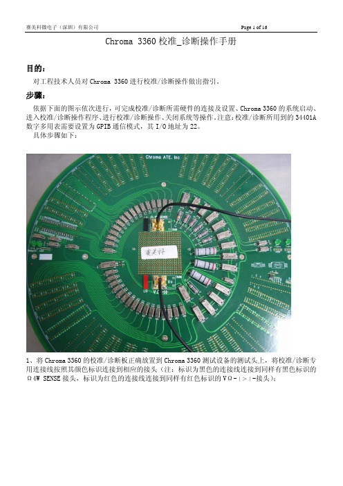
Chroma 3360校准_诊断操作手册目的:对工程技术人员对Chroma 3360进行校准/诊断操作做出指引。
步骤:依据下面的图示依次进行,可完成校准/诊断所需硬件的连接及设置、Chroma 3360的系统启动、进入校准/诊断操作程序、进行校准/诊断操作、关闭系统等操作。
注意:校准/诊断所用到的34401A 数字多用表需要设置为GPIB通信模式,其I/O地址为22。
具体步骤如下:1、将Chroma 3360的校准/诊断板正确放置到Chroma 3360测试设备的测试头上,将校准/诊断专用连接线按照其颜色标识连接到相应的接头(注:标识为黑色的连接线连接到同样有黑色标识的Ω4W SENSE接头,标识为红色的连接线连接到同样有红色标识的VΩ-∣>∣-接头);2、将GPIB通信线一端连接Chroma 3360测试机电脑上的GPIB通信接口,一端连接34401A数字多用表后面的GPIB通信接口;3、将校准/诊断专用连接线按照其颜色标识连接到34401A数字多用表相应的接头(注:标识为黑Starter图标,准备打开Chroma 3360测试系统软件;是否显示并选中图示内容,如不是则需要检查测试头与电脑连线并重启软件;8、在ATE Starter面板上点击“ON”按钮,准备启动Chroma 3360测试系统电源;9、点击“OK”按钮,忽略“Environment checked error!”信息;10、点击“Yes”按钮,确认启动Chroma 3360测试系统电源;11、当ATE Starter面板内显示图示信息时,说明已经正确启动Chroma 3360测试系统电源并完12、选中System Control面板,点击“Login”按钮,准备登录Chroma 3360测试软件;13、在“User Login”对话框中依次输入“Account:app”、“Password:app”,然后点击“OK”14、在登陆后的“System Control”面板里中,点选“FE”页面;15、在“FE”页面右侧,找到“Maintenance Utility”图标;16、双击“Maintenance Utility”图标,打开校准/诊断程序;17、在弹出的Maintenance面板中,点击菜单栏中“File”按钮;18、在弹出的下拉菜单中,点击“Load DC Calibration”项,准备进行DC参数校准操作;19、在图示界面中,选中“Select All Items”项,准备进行DC参数校准操作;操作;21、完成DC参数校准操作后,在“File”下拉菜单中点击“Un-Load Plan”项,准备退出DC参数校准;22、点击弹出的Confirm对话框中的“Yes”按钮,确认退出DC参数校准;23、依照上述17-22步骤,依次完成DC参数诊断、AC参数校准、AC参数诊断;注意,在进行AC参数校准/诊断前,需要将校准/诊断板从Chroma 3360测试设备的测试头上取下;24、完成所有校准/诊断操作后,点击Maintenance面板右上角的关闭按钮,退出校准/诊断界面;25、点击弹出的Confirm对话框中的“Yes”按钮,确认退出校准/诊断界面;26、在“System Control”面板里中,点击“Logout”按钮,准备退出“app”登陆权限。
迈尼-克路特移动测试设备编程手册说明书
Mini-Circuits Portable Test Equipment (PTE) Programming Manual Table of ContentsChapter 1 - Introduction and Overview ....................................................... 1-2 Chapter 2 - RF Switch Matrices ................................................................... 2-1 Chapter 3 - Synthesized Signal Generators .................................................. 3-1 Chapter 4 - Power Sensors .......................................................................... 4-1 Chapter 5 - Frequency Counters .................................................................. 5-1 Chapter 6 - Programmable Attenuators ...................................................... 6-1 Chapter 7 - Input/Output (IO) Control Boxes ............................................... 7-1 Chapter 8 - USB & RS232 to SPI Converters ................................................ 8-1 Chapter 9 – ZTM-X Modular Test Systems ……………………………..................... 9-1 Appendices ................................................................................................. A-1 Appendix A - Conversion Tables ………………………………………………………………………………... A-3 Appendix B - Examples for Python Programming ……………………………….......................... B-1 Appendix C - Examples for C Programming ................................................................... C-1 Appendix D - Examples for Visual Basic Programming .................................................. D-1 Appendix E - Examples for Visual C++ Programming …………………………………………......... E-1 Appendix F - Examples for Visual C# Programming ....................................................... F-1 Appendix G - Examples for LabVIEW ............................................................................ G-1 Appendix H - Examples for MatLab .............................................................................. H-1 Appendix I - Examples for Agilent VEE .......................................................................... I-1Chapter 1 -Introduction and OverviewChapter 1 - Introduction and Overview ....................................................... 1-2 1.1 - Overview ............................................................................................................ 1-3 1.2 - Operating in a Windows Environment ................................................................ 1-41.2.1 - The DLL (Dynamic Link Library) Concept .......................................................................... 1-41.2.2 - Summary of DLL Files for the Mini-Circuits PTE Range .................................................... 1-51.2.3 - ActiveX COM Object ......................................................................................................... 1-61.2.4 - Class Library .............................................................................................. 1-8 1.3 - Operating in a Linux Environment ....................................................................... 1-9 1.4 - Notices ............................................................................................................. 1-101.4.1 - Registered Trademarks ................................................................................................... 1-101.4.2 - Copyright Information .................................................................................................... 1-101.1 -OverviewThis Programming Manual is intended for customers wishing to create their own interface for Mini-Circuits' USB controlled Portable Test Equipment (PTE). For instructions on using thesupplied GUI program, or connecting the PTE hardware, please see the User Guide of therelevant model.Mini-Circuits offers support over a variety of operating systems, programming environments and third party applications.Support for Windows® operating systems is provided through the Microsoft®.NET® andActiveX® frameworks to allow the user to develop customized control applications. Support for Linux® operating systems is accomplished using the standard libhid and libusb libraries.Mini-Circuits has experience with a wide variety of environments including (but not limitedto):∙Visual Basic®, Visual C#®, Visual C++®∙Delphi®∙Borland C++®∙CVI®∙LabVIEW®∙MATLAB®∙Python®∙Agilent VEE®The Mini-Circuits PTE CD package includes a GUI program installation, DLL Objects (32/64bit), Linux support, project examples for third party software, and detailed user manuals.The latest CD version is available for download at:/support/software_download.htmlFor details on individual models, application notes, GUI installation instructions and userguides please see:/products/PortableTestEquipment.shtmlFiles made available for download from the Mini-Circuits website are subject to Mini-Circuits’terms of use which are available on the website.1.2 -Operating in a Windows Environment1.2.1 -The DLL (Dynamic Link Library) ConceptThe Dynamic Link Library concept is Microsoft's implementation of the shared libraryconcept in the Windows environment.DLLs provide a mechanism for shared code and data, intended to allow a developer todistribute applications without requiring code to be re-linked or recompiled.Mini-Circuits' CD package provides DLL Objects designed to allow your own softwareapplication to interface with the functions of Mini-Circuits' PTE, see Figure 1.Figure 1: DLL Interface ConceptMini-Circuits’ CD package provides two DLL files, the choice of which file to use is dictated by the user’s operating system:1.ActiveX com objectDesigned to be used in any programming environment that supports third partyActiveX COM (Component Object Model) compliant applications.The ActiveX file should be registered using RegSvr32 (see following sections fordetails). Class LibraryDesigned to be a logical unit of functionality that runs under the control of the system.1.2.2 -Summary of DLL Files for the Mini-Circuits PTE RangeActiveX Com objects and class libraries can be downloaded from the Mini-Circuits website at:/support/software_download.html1.2.3 -ActiveX COM ObjectActiveX COM object DLL files are designed to be used with both 32 bit and 64 bit Windowsoperating systems. A 32 bit programming environment that is compatible with ActiveX isrequired. To develop 64 bit applications, the Class library should be usedinstead.Supported Programming EnvironmentsMini-Circuits’ PTE devices have been tested in the following programming environments.This is not an exhaustive list and the DLL file is designed to operate in most environmentsthat support ActiveX functionality. Please contact Mini-Circuits for support.∙Visual Studio® 6 (Visual C++ and Visual Basic)∙LabVIEW 8.0 or newer∙MATLAB 7 or newer∙Delphi∙Borland C++∙Agilent VEE∙PythonInstallation1.Copy the DLL file to the correct directory:a.For 32 bit Windows operating systems this is C:\WINDOWS\System32b.For 64 bit Windows operating systems this is C:\WINDOWS\SysWOW642.Open the Command Prompt:a.For Windows XP® (see Fig 1.1.2a):i.Select “All Programs” and then “Accessories” from the Start Menuii.Click on “Command Prompt” to openb.For later versions of the Windows operating system you will need to haveAdministrator privileges in order to run the Command Prompt in “Elevated”mode (see Fig 1.1.2b for Windows 7 example and Fig 1.1.2c for Windows 8):i.Open the Start Menu/Start Screen and t ype “Command Prompt”ii.Right-click on the shortcut for the Command Promptiii.S elect “Run as Administrator”iv.You may be prompted to enter the log in details for an Administratoraccount if the current user does not have Administrator privileges on thelocal PCe regsvr32 to register the DLL:a.For 32 bit Windows operating systems type (see Fig 1.1.2d):\WINDOWS\System32\Regsvr32 \WINDOWS\System32\mcl_pm.dll(where mcl_pm.dll is the name of the relevant DLL)b.For 64 bit Windows operating systems type (see Fig 1.1.2e):\WINDOWS\SysWOW64\Regsvr32 \WINDOWS\SysWOW64\mcl_pm.dll(where mcl_pm.dll is the name of the relevant DLL)4.Hit enter to confirm and a message box will appear to advise of successful registration.Fig 1.1.2a: Opening the Command Prompt in Windows XP Fig 1.1.2b: Opening the Command Prompt in Windows 7Fig 1.1.2c: Opening the Command Prompt in Windows 8Fig 1.1.2d: Registering the DLL in a 32 bit environmentFig 1.1.2e: Registering the DLL in a 64 bit environment1.2.4 Class Library class libraries are designed to be used with both 32 bit and 64 bit Windowsoperating systems. To develop 64 bit applications the user must have both a 64 bit operating system and 64 bit programming environment. However, the class library isalso compatible with 32 bit programming environments.Supported Programming EnvironmentsMini-Circuits’ PTE devices have been tested in the following programming environments.This is not an exhaustive list and the DLL file is designed to operate in most environmentsthat support functionality. Please contact Mini-Circuits for support.∙National Instruments CVI∙ (Visual C++, Visual , Visual C# 2003 or newer)∙LabVIEW 2009 or newer∙MATLAB 2008 or newer∙Delphi∙Borland C++Installation1.Copy the DLL file to the correct directorya.For 32 bit Windows operating systems this is C:\WINDOWS\System32b.For 64 bit Windows operating systems this is C:\WINDOWS\SysWOW642.No registration is required1.3 -Operating in a Linux EnvironmentTo open a connection to Mini-Circuits PTE devices, the Vendor ID and Product ID arerequired:∙Mini-Circuits Vendor ID: 0x20CE∙Mini-Circuits Product IDs:▪Switch Matrices: 0x22▪Signal Generators: 0x12▪Power Meters: 0x11▪Frequency Counters: 0x10▪Digital Step Attenuators: 0x23▪Input/Output Control Boxes: 0x21▪USB/RS232/SPI Converters: 0x25▪ZTM-X Modular Test Systems: 0x22Communication with each PTE device is carried out by way of USB Interrupt. The transmitted and received buffer sizes are 64 Bytes each:∙Transmit Array = [Byte 0][Byte1][Byte2]…[Byte 63]∙Returned Array = [Byte 0][Byte1][Byte2]…[Byte 63]In most cases, the full 64 byte buffer si ze is not needed so any unused bytes become “don’t care” bytes; they can take on any value without affecting the operation of the PTE.1.4 -Notices1.4.1 -Registered TrademarksMicrosoft, Windows, Windows XP, Windows 7, ActiveX, , Visual Basic, Visual C#, and Visual C++ are registered trademarks of Microsoft Corporation.Linux is a registered trademark of Linus Torvalds.LabVIEW is a registered trademark of National Instruments Corporation.Delphi is a registered trademark of Codegear LLC.MATLAB is a registered trademark of MathWorks, Inc.Agilent VEE is a registered trademark of Agilent.The above trademarks and all other trademarks cited within the Programming Manual are the property of their respective owners.Neither Mini-Circuits nor the Mini-Circuits Portable Test Equipment are affiliated with orendorsed or sponsored by the owners of the above referenced trademarks set forth in this manual.Mini-Circuits and the Mini-Circuits logo are registered trademarks of Scientific Components Corporation.1.4.2 -Copyright InformationThis Programming Manual is owned by Mini-Circuits and is protected by copyright,trademark and other intellectual property laws.© Copyright 2013 Scientific Components Corporation.。
详尽的硬件测试程序
详尽的硬件测试程序简介本文档旨在提供一份详尽的硬件测试程序,旨在确保硬件设备的正常运行和性能表现。
该测试程序适用于各种硬件设备,包括但不限于计算机、服务器、网络设备等。
通过执行该测试程序,可以及时发现并解决硬件故障,提高硬件设备的可靠性和稳定性。
测试步骤1. 准备测试环境:- 确保所有硬件设备处于正常工作状态。
- 清理硬件设备表面,确保无灰尘或杂物。
- 连接所有必要的电缆和接口。
2. 运行基本功能测试:- 启动硬件设备并检查启动过程中是否出现异常。
- 检查设备的基本功能,如显示器是否显示正常,鼠标和键盘是否响应等。
3. 进行性能测试:- 运行性能测试工具,如性能监控软件或负载测试工具。
- 检查硬件设备在高负载情况下的工作表现,如CPU使用率、内存占用、磁盘读写速度等。
4. 进行稳定性测试:- 运行稳定性测试工具,如压力测试工具或循环测试工具。
- 检查硬件设备在长时间运行过程中是否出现异常,如死机、重启等。
5. 进行连接测试:- 如果硬件设备需要连接到其他设备或网络,请确保连接的可靠性和稳定性。
- 检查连接的速度、延迟和传输质量等参数。
6. 进行安全性测试:- 检查硬件设备的安全性能,如防火墙、加密功能等。
- 尝试绕过或攻击设备,以验证其安全性能和防护能力。
7. 记录测试结果:- 对每个测试步骤的结果进行记录,包括测试日期、测试者、测试环境等信息。
- 记录测试过程中发现的问题和解决方案。
8. 分析和优化:- 分析测试结果,找出硬件设备存在的问题和瓶颈。
- 根据分析结果,优化硬件设备的配置和性能。
注意事项- 在执行测试程序之前,务必备份重要数据,以防止意外数据丢失。
- 在测试过程中,注意观察硬件设备的温度、噪音和其他异常情况。
- 如果遇到无法解决的问题,及时向硬件设备厂商或专业技术人员寻求帮助。
结论通过执行上述详尽的硬件测试程序,可以提高硬件设备的可靠性和稳定性,发现和解决潜在的硬件故障,确保硬件设备的正常运行和性能表现。
3360P ATE测试机系统介绍1

Pogo Pin No 22 23 24 25 26 27 28 29 30 31 32 33 34 35 36 37 38 39 40 41 42
3360 Training P.20
W O R K I N G
O N
B E T T E R
S O L U T I O N S
SPBUS-總線板
STBUS PoGo Pin Define Pogo Pin No define define 1 2 UR0 UR16 3 UR1 UR17 4 UR2 UR18 5 UR3 UR19 6 UR4 UR20 7 UR5 UR21 8 UR6 UR22 9 UR7 UR23 10 5V 5V 11 UR8 UR24 12 UR9 UR25 13 UR10 UR26 14 UR11 UR27 15 UR12 UR28 16 UR13 UR29 17 UR14 UR30 18 UR15 UR31 19 RELAY 5V RELAY 5V 20 21 RELAY 5V RELAY 5V
圖形記憶體容量 SPM : 8M RPM : 256K FPM : 1K
LXPG2 PoGo Pin Define
Pogo Pin No 1 2 3 4 5 6 7 8 9 10 11 12 13 14 15 16 17 18 19 20 21 define AG IMatch_Pass +15V -15V define AG +15V -15V +3.3V Pogo Pin No 22 23 24 25 26 27 28 29 30 31 32 33 34 35 36 37 38 39 40 41 42
4. CRAFT Starter按下Apply
2
UAVP 汉语手册

手册用於建造與操作專業的悬停平台特征这项发展的目标是要建造一个普遍的悬停平台包括以下特征:单一电子板,额外的元件有馬達,馬達控制器,遥控系统和机身/框架电缆布线容易防干扰设计,不需要特别错综复杂的技能可編程信號更新(到250 hz)自定义设置为不同的马达/控制器/螺旋桨组合另外2个遥控渠道为控制伺服机(照相机角度)7组LED驱动渠道,每一组可驱动500mA!音响信号作为低电池,无线信号中断警告和寻找指引陀螺仪:3陀螺模块adxrs300/150(推荐)或1x adxrs300/150和1xidg300可通過RS232 或遥控-发射机更改編程參量失去控制时自动降落伞系统触发器可选数码加速度传感器lis3lv02dq可选数字指南针传感器hmc6352可选数字气压传感器smd500可选全球衛星定位(在开发中:GPS (ublox)选择项允许某种程度的个人宁愿,一些选项可以选择或省略。
在所有情况下,这些选项可以在以后添加或删除。
但是一些选项会对其它的选择宁愿有影响。
所需的部分元件会在建造程序中的每个选项中分别提及零件名单基本远程控制模型设备4 X 无刷马达2 X 顺时针方向转螺旋桨(即epp1045或其他,与使用的马达相合适)2 X 逆时针方向转螺旋桨(即epp1045或其他,与使用的马达相合适)4 X 无刷控制器(PWM 或TWI/i2c),与马达的电力要求相同,yge I系列或Holger’s i2c 控制器。
这些无刷控制器给予很好的表现,但其他模式也可以使用。
1 x 简单的5渠道无线电发射,接收器(推荐7渠道)或者也可以用有PPM复合输出的接收器电子零件为了节省空间和重量,大部分的电子元件是SMD封装。
用铅笔型烙铁和稳定的手,贴片零件是很容易焊接的. 全部电子元件都是标准零件及包装.1 X 印刷电路板,在www.lipoly.de 或 购买1 × U1 pic16f876或876a (dil28 ,165117 )与目前的Hex文件编程,预先编程的芯片可以由作者或www.lipoly.de 或 购买1 x U2 TPIC6B595N (DIL20)1 × U3 tl431稳压器(TO92)1 X 石英16 MHz (hc49u )6 x R1,R2,R3,R18,R19,R23 SMD 电阻器10k 5% (0805)15 x R6,R7,R8,R10,R11,R12,R13,R14,R15,R21,R17,R24,R25,R26,R27 SMD 电阻器4,7k 5% (0805)3 x R4,R9,R20 SMD 电阻器1k 5% (0805)1 x R5 SMD 电阻器2,2k (0805)1 x R22 SMD 电阻器68 5% (0805)4 x R28,R29,R30,R31 SMD 电阻器180 5% (0805)1 x R16 SMD 电阻器100 5% (0805)4 x D1,D2,D3,D4 SMD-二极管LL4148 (SOD80) 注意PCB的方向!1 x D5 SMD LED 蓝色30mA, PLCC21 x D6 SMD LED 红色30mA, PLCC21 x D7 SMD LED 绿色30mA, PLCC21 x D8 SMD LED 黄色30mA, PLCC23 x Q1, Q2, Q3 NPN 晶体管BC548B 或相似的(TO92)4 x C1, C2, C6, C7 SMD 电容器100nF (0805)2 x C4, C5 SMD 电容器22pF (0805)2 x C8, C9 SMD 钽电容器1μF1 x C3两极电容器100μF 10V, 辐形包装, 注意PCB 的方向!1 × L1的电感线圈100至220 μ h ,0,1A ,轴向包装1x 所有K 36pin 插针式连接器RM2,54 平直,被金镀锌, 可拆2x 所有K 12pin 插座连接器RM2,54 平直, 可拆2X U1 IC 插座dil14 (2个安装一排做成dil28 )选择"LEDs"大家都希望有所不同照明效果任何类型的LED 都可以。
3620-TTP Tester PM作业指导书
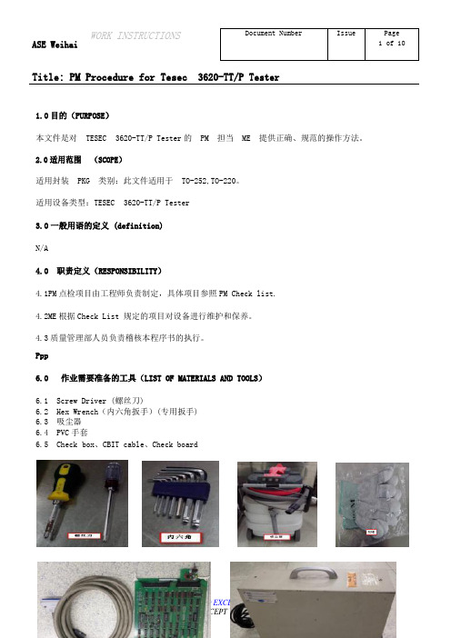
Title: PM Procedure for Tesec 3620-TT/P Tester1.0目的(PURPOSE)本文件是对TESEC 3620-TT/P Tester的PM 担当ME 提供正确、规范的操作方法。
2.0适用范围(SCOPE)适用封装PKG 类别:此文件适用于TO-252,TO-220。
适用设备类型:TESEC 3620-TT/P Tester3.0一般用语的定义 (definition)N/A4.0 职责定义(RESPONSIBILITY)4.1PM点检项目由工程师负责制定,具体项目参照PM Check list.4.2ME根据Check List 规定的项目对设备进行维护和保养。
4.3质量管理部人员负责稽核本程序书的执行。
•Ppp6.0 作业需要准备的工具(LIST OF MATERIALS AND TOOLS)6.1 Screw Driver (螺丝刀)6.2 Hex Wrench(内六角扳手)(专用扳手)6.3 吸尘器6.4 PVC手套6.5 Check box、CBIT cable、Check boardTitle: PM Procedure for Tesec 3620-TT/P Tester7.0 注意事项( PREPARATORY PROCEEDINGS AND NOTICE ITEMS)7.1ME在PM作业前,一定先要全面检查设备的状态,看设备里面有没有产品,确实需要时用DUMMY 进行作业。
7.2 作业前先把各种工具和材料准备好,以节约停止时间。
7.3 作业前把PM LOG SHEET 准备好,按照上面的内容由上到下逐项完成,完成一项在PM LOG SHEET上记录一次,直到所有事项完成。
7.4 作业时一定要注意安全,有紧急情况时立即按下“紧急停止按钮。
8.0 PM CHECK LIST (点检项目表)9.0PM详细操作方法9.1System内部清理9.1.1 将Tester 关机,Tester 的关机顺序:退出测试软件-关闭windows 软件-关闭测试机电源-拔下电脑电源线,关机后将主机箱上所有线缆拆掉,拆卸前记录各种线缆的连接位置,将主机平放后打开机箱盖,先用吸尘器清理机箱内灰尘,再将I/O 板卡以及内存条金手指用无尘布进行擦拭,;清理完毕后,将主机Title: PM Procedure for Tesec 3620-TT/P Tester所有线缆连接,开启电脑。
测试机台调试

? (3)插入探针,可找寻输出PIN,可找寻每一 PIN输出点位.
? (4)可查看测试结果之统计资料。
? (1)测试机的各项操作的设定如声音、亮度等。 ? (2)测试机的各项环境的操作设定:如测试文
件类型、测试结果显示、不良品报警声等。 ? (3)测试机的显示日期和时间的设定。 ? (4)管理密码设定,用于设定管理密码,机台
(功能设定和分析模式
)
? 测试机的主要页面有:(按下Para键可显示出以下菜单)
? 测试模式设定-短断路设定-导通电阻设定-被动元件设定-高压条件设定-测试项目设定
? 1.测试模式设定(LCD显示画面如下
)
(1)测试启动方式设定为 “自动” (2)启动延时设定为 “0”,如产品有特殊要
求则按要求设定(作用:延迟设定的时间再进
(功能设定和分析模式
)
? 测试机的主要页面有:(按下Para键可显示出以下菜单)
? 测试模式设定-短断路设定-导通电阻设定-被动元件设定-高压条件设定-测试项目设定
(7)瞬短断测试时间 0-999.9S (按需求设定) 0s:在侦测瞬短断时,机台会一直侦测,直到拔下
待测物停止 (即为无限摇摆) 0.1S-999.9s: 在侦测瞬短断时,机台会按设定的时
行测试)
(3)导通错误循环测试: 设定为“开”
开:当待重复测试,可
解决因产品与治具接触不良造成的误判。
(7)测试错误设定为“停止测试” (8)循环待测回路状态设定为“无”
关:当待测物回路结构中有导通不良时,机台 立即显示不良的回路结构,不做重复测试。 注:当此项设定为开时,无论回路结构中有一 个或是多个导通不良,机台都只显示一个导通 不良的回路结构,当此项设定为关时,机台将 显示全部导通不良的回路结构 。 (4)元件错误循环测试:当元件测到不良时,重 复测试元件。 (5)连续测试次数设定为 “0” (6)连续测试间隔设定 “0”
QTP基本讲解第一本PPT课件
,每个对象模型都有一个可以唯一标识对象的
属性列表,这个属性列表是可以设置的,它就 是Object Identification QTP上方菜单栏→Tools→Object Identification Mandatory Properties :必要属性区域 Assistive Properties :辅助属性区域 Add/Remove :新增或移除属性 Enable Smart Identification:对象属性的智 能识别开关
脚本录制
录制系统的三种模式 正常录制模式
Products
直接对对象的操作,并不能保证识别程序中所有的对象,录制方法如下 (1)QTP上方菜单栏→Automation→Record。 (2)直接使用快捷键“F3”。 (3)在QTP界面上点击正常录制图标
录制的三种模式
最新课件
15
脚本录制
模拟录制模式
最新课件
10
QTP自动化测试录制与回放
A 帮助文档
两种视图 D
主要 内容
脚本回放 C
最新课件
B 脚本录制
11
QTP帮助文档
QTP帮助文档总览了所有的知识点,是学习 的最好良师,具体的使用方法是运行QTP后通 过键盘F1启动。也可以在专家视图中双击选中 代码按F1精确查看
帮助文档里具体内容大致分为下面几个区域: Description:方法描述 Syntax:语法细节 Return Type:返回类型 Example:举例说明
最新课件
7
何时不适合自动化测试
何时不适合自动化测试
硬件测试培训课件(PPT82页)

测试前准备
4、测试用例 测试用例更多的是需要描述测试方法,测试步骤
,测试的预期效果,需要达到的指标。需要更 加详细的对每一条测试项目进行描述; 测试用例是直接用来指导测试的,所以对测试项 目的描述需要更具体,更便于参考操作;
课件大纲
硬件测试概述 测试前准备 硬件测试的种类与操作 硬件测试的级别 可靠性测试 测试问题的解决 测试效果评估 测试规范的制定 测试人员的培养
硬件测试的级别
1、黑盒测试与白盒测试 黑盒测试注重于测试功能性需求,将测试对象
看成一个黑盒子,对外只有输入、输出。 设计黑盒测试用例只对于表现在外接口的各 种输入,对不同的输入,测试其表现出来的 输出,从而达到测试功能的目的。 白盒测试主要测试模块内部的逻辑细节,各个 独立的逻辑路径。黑盒测试不管多么全面, 都可能忽略这些错误。 设计白盒测试用例需要构造到信号、逻辑或 消息级。
测试前准备
测试用例的一般格式: 测试用例编号; 测试项目(模块或单元); 测试子项目(子项目描述); 测试级别(必测,选择,可测); 测试条件(环境、仪器等相关要求); 测试步骤和方法(具体细致的操作方法); 应达到的指标和预期效果; 备注;
测试前准备
5、测试需求的来源
一切测试的需求都来自于产品设计的规格,规格来自 于用户的需求。因此我们的测试是针对产品规格的测试 。具体可以从以下几方面进行考虑: 产品设计功能: 根据功能的实现,分别对实现该功能的各个环节进行测 试,从硬件、单板软件、高层软件到用户界面,只有各 个环节都畅通无阻,才能保证该功能的正常实现; 可靠性: 备份、倒换、插拔、互助、自愈等;
迈尼-电路小型测试设备编程指南.pdf_1719238162.334294说明书
Chapter 5 -Frequency CountersChapter 5 - Frequency Counters .................................................................. 5-1 5.1 - Operating in a Windows Environment ................................................................ 5-25.1.1 - Referencing the DLL Library .............................................................................................. 5-25.1.2 - Summary of DLL Functions ............................................................................................... 5-35.1.3 - Detailed Description of DLL Functions.............................................................................. 5-45.1.3 (a) - Connect to Frequency Counter ................................................................................ 5-45.1.3 (b) - Disconnect from Frequency Counter ....................................................................... 5-55.1.3 (c) - Get List of Connected Serial Numbers ..................................................................... 5-65.1.3 (d) - Get Status ................................................................................................................. 5-75.1.3 (e) - Read Model Name of Frequency Counter ............................................................... 5-85.1.3 (f) - Read Serial Number of Frequency Counter .............................................................. 5-95.1.3 (g) - Read Frequency of Frequency Counter ................................................................. 5-105.1.3 (h) - Set Range of Frequency Counter ........................................................................... 5-115.1.3 (i) - Get Range of Frequency Counter ............................................................................ 5-125.1.3 (j) - Set Sample Time ...................................................................................................... 5-135.1.3 (k) - Get Firmware Version ............................................................................................ 5-14 5.2 - Operating in a Linux Environment ..................................................................... 5-155.2.1 - Summary of Commands ................................................................................................. 5-155.2.2 - Detailed Description of Commands ................................................................................ 5-165.2.2 (a) - Get Device Model Name ........................................................................................ 5-165.2.2 (b) - Get Device Serial Number ...................................................................................... 5-175.2.3 - Get Frequency and Range .............................................................................................. 5-185.2.3 (a) - Set Range ............................................................................................................... 5-205.2.3 (b) - Set Sample Time .................................................................................................... 5-215.1 -Operating in a Windows Environment5.1.1 -Referencing the DLL LibraryThe DLL file is installed in the host PC’s system folders using the steps outlined above. Inorder to use the DLL functionality, some programming environments will require the user to set a reference to the relevant DLL file, usually through a built in GUI in the programmingenvironment.Once this is done, the user just needs to instantiate a new instance of the USB_FreqCounter object in order to use the frequency counter functions. The details of this vary greatlybetween programming environments and languages but Mini-Circuits can provide detailed support on request. A new frequency counter object would need to be initialized for every USB frequency counter that the user wishes to control. In the following examples, MyPTE1 and MyPTE2 will be used as names of 2 declared sensor objects.Examples5.1.2 -Summary of DLL FunctionsThe following functions are defined in both of the DLL files. Please see the following sections for a full description of their structure and implementation.a)Short Connect (Optional String SN)b)Void Disconnect ()c)Short Get_Available_SN_List (String* SN_List)d)Short GetStatus ()e)Short Read_ModelName (String ModelName)f)Short Read_SN (String SN)g)Short ReadFreq (Double RetFreq)h)Short SetRange (Short RequestedRange)i)String GetRange ()j)Short SetSampleTime (Float SampleTime_sec)k)Short GetFirmware ()5.1.3 -Detailed Description of DLL Functions5.1.3 (a) -Connect to Frequency CounterDeclarationShort Connect(Optional String SN)DescriptionThis function is called to initialize the connection to a USB frequency counter. If multiple sensors are connected to the same computer, then the serial number should be included, otherwise this can be omitted. The connection process can take a few milliseconds so it is recommended that the connection be made once at the beginning of the routine and left open until the sensor is no longer needed. The sensor should be disconnected oncompletion of the program using the Disconnect function.ParametersReturn ValuesExamplesSee AlsoDisconnect from Frequency Counter5.1.3 (b) -Disconnect from Frequency CounterDeclarationVoid Disconnect()DescriptionThis function is called to close the connection to the frequency counter. It is stronglyrecommended that this function is used prior to ending the program. Failure to do so mayresult in a connection problem with the device. Should this occur, shut down the programand unplug the frequency counter from the computer, then reconnect the frequency counter before attempting to start again.ParametersReturn ValuesExamplesSee AlsoConnect to Frequency Counter5.1.3 (c) -Get List of Connected Serial NumbersDeclarationShort Get_Available_SN_List(String SN_List)DescriptionThis function takes a user defined variable and updates it with a list of serial numbers for all available (currently connected) control boxes.ParametersReturn ValuesExamplesConnect to Frequency CounterRead Serial Number of Frequency Counter5.1.3 (d) -Get StatusDeclarationShort Get_Status()DescriptionThis function checks whether the USB connection to the frequency counter is still active. ParametersReturn ValuesExamplesSee AlsoConnect to Frequency Counter5.1.3 (e) -Read Model Name of Frequency CounterDeclarationShort Read_ModelName(String ModelName)DescriptionThis function is called to determine the Mini-Circuits part number of the connected frequency counter.ParametersReturn ValuesExamplesSee AlsoRead Serial Number of Frequency Counter5.1.3 (f) -Read Serial Number of Frequency CounterDeclarationShort Read_SN(String SN)DescriptionThis function is called to determine the serial number of the connected frequency counter. ParametersReturn ValuesExamplesSee AlsoRead Model Name of Frequency Counter5.1.3 (g) -Read Frequency of Frequency CounterDeclarationShort ReadFreq(Double RetFreq)DescriptionThis function returns the frequency in MHz of the signal at the frequency counter’s RF input. ParametersReturn ValuesExamplesSee AlsoSet Sample Time5.1.3 (h) -Set Range of Frequency CounterDeclarationShort SetRange(Short RequestedRange)DescriptionThis function sets the range of the frequency counter. By default the frequency counter is in “Auto Range” mode and will automatically set the correct frequency range, this process will take typically 50ms. If the frequency range of the input signal is known then the user caneliminate this delay by specifying the appropriate range. The options are:ParametersReturn ValuesExamplesSee AlsoGet Range of Frequency Counter5.1.3 (i) -Get Range of Frequency CounterDeclarationString GetRange()DescriptionThis function returns the range setting that the frequency counter is currently using for measurements.ParametersReturn ValuesExamplesSee AlsoSet Range of Frequency Counter5.1.3 (j) -Set Sample TimeDeclarationShort SetSampleTime(Float SampleTime_sec)DescriptionThis function sets the sample time for the frequency measurements, in 0.1 second steps up to 1 second, or 1 second steps up to 3 seconds. The default sample time is 1 second. ParametersReturn ValuesExamplesSee AlsoRead Frequency of Frequency Counter5.1.3 (k) -Get Firmware VersionDeclarationShort Get_Firmware()DescriptionThis function returns the internal firmware version of the frequency counter. ParametersReturn ValuesExamples5.2 -Operating in a Linux EnvironmentTo open a connection to Mini-Circuits RF Frequency Counter, the Vendor ID and Product ID are required:∙Mini-Circuits Vendor ID: 0x20CE∙Frequency counter Product ID: 0x10Communication with the frequency counter is carried out by way of USB Interrupt. Thetransmitted and received buffer sizes are 64 Bytes each:∙Transmit Array = [Byte 0][Byte1][Byte2]…[Byte 63]∙Returned Array = [Byte 0][Byte1][Byte2]…[Byte 63]In most cases, the full 64 byte buffer size is not needed so any unused bytes become “don’t care” bytes; they can take on any value without affecting the operation of the frequencycounter.A worked example is included in Appendix C of this document. The example uses the libhidand libusb libraries to interface with the frequency counter as a USB HID (Human InterfaceDevice).5.2.1 -Summary of CommandsThe commands that can be sent to the frequency counter are summarized in the table below and detailed on the following pages.5.2.2 -Detailed Description of Commands5.2.2 (a) -Get Device Model NameDescriptionThis function determines the Mini-Circuits part number of the connected frequency counter.Send code 40 in BYTE0 of the transmit array. BYTE1 through to BYTE63 are “don’t care”bytes and can be any value.The model name is represented as a series of ASCII characters in the returned array, starting from BYTE1. The final ASCII character is contained in the byte immediately preceding thefirst zero value byte. All subsequent bytes up to BYTE63 are “don’t care” bytes and could be any value.Transmit ArrayReturned ArrayExampleThe following array would be returned for Mini-Circuits’ UFC-6000 frequency counter. See Appendix A for conversions between decimal, binary and ASCII characters.See AlsoGet Device Serial Number5.2.2 (b) -Get Device Serial NumberDescriptionThis function determines the serial number of the connected frequency counter.Send code 41 in BYTE0 of the transmit array. BYTE1 through to BYTE63 are “don’t care”bytes and can be any value.The serial number is represented as a series of ASCII characters in the returned array,starting from BYTE1. The final ASCII character is contained in the byte immediatelypre ceding the first zero value byte. All subsequent bytes up to BYTE63 are “don’t care” bytes and could be any value.Transmit ArrayReturned ArrayExampleThe following example indicates that the current frequency counter has serial number1100040023. See Appendix A for conversions between decimal, binary and ASCII characters.See AlsoGet Device Model Name5.2.3 -Get Frequency and RangeDescriptionThis function returns the current frequency measurement and the frequency counter’s range setting.The transmit array contains 2 in BYTE0. BYTE1 to BYTE63 are “don’t care” bytes and could be any value. The returned array is made up of the following bytes:∙BYTE0o Code 2∙BYTE1 to BYTE16o Series of ASCII character codes representing the range setting in the format“Range: 0”, padded with space characters∙BYTE17 to BYTE32o Series of ASCII character codes representing the measured frequency in theformat “0000.0000 MHz”, padded with space characters∙BYTE33 to BYTE63o Can be any value (“don’t care” bytes)Transmit ArrayReturned ArrayExampleThe following array would be returned for a frequency measurement of 300.0005MHz with the range at setting 3:See AlsoSet Range5.2.3 (a) -Set RangeDescriptionThis function sets the range of the frequency counter. By default the frequency counter is in “Auto Range” mode and will automatically set the correct frequency range, this process will take typically 50ms. If the frequency range of the input signal is known then the user caneliminate this delay by specifying the appropriate range. The options are:The transmit array is made up of the following bytes:∙BYTE0o Code 4∙BYTE1o An integer value from 1 to 4 to set the range, or 255 for “Auto Range”∙BYTE2 to BYTE63o Can be any value (“don’t care” bytes)Transmit ArrayReturned ArrayExampleSend the following transmit array to set the frequency counter to “Auto Range”:See AlsoGet Frequency and RangeSet Sample Time5.2.3 (b) -Set Sample TimeDescriptionThis function sets the sample time for the frequency measurements, in 0.1 second steps up to 1 second, or 1 second steps up to 3 seconds. The default sample time is 1 second.The transmit array is made up of the following bytes:∙BYTE0o Code 3∙BYTE1o An integer value representing the sample time in seconds multiplied by 10.This allows a precision of 1 decimal place to be set.∙BYTE2 to BYTE63o Can be any value (“don’t care” bytes)Transmit ArrayReturned ArrayExampleTo set the sample time to 0.3 seconds, multiply by 10 to get an integer 3 in BYTE1. The full transmit array would be:See AlsoSet Range。
3360P测试机测试程式开发讲义
Working on Better Solutions Version 1.0 Copyright © 2007 ,CHROMA Inc.
9
測試程序檔案架構1
Working on Better Solutions Version 1.0 Copyright © 2007 ,CHROMA Inc.
10
ACTIV E LOAD
OUTPUT FORMAT EDGE
WINDOW
MASK/ENABL E
COMPARATO R
Z DATA
Working on Better Solutions Version 1.0 Copyright © 2007 ,CHROMA Inc.
4
數字通道方塊圖
IN PU T WAV E F O R M =F-D ATA +DTG/SBCM K +IN PU T FO R M AT
測試程序檔案架構2
Working on Better Solutions Version 1.0 Copyright © 2007 ,CHROMA Inc.
11
圖形/主程序-編譯
Source program (XXXXXX.pat)
Compiling
Object program (XXXXXX.ppo)
pin_type:管腳種類
IN OUT IO DPS PREF LCD UR GND
輸入腳. 輸出腳. 雙向腳. 電源腳,使用DPS供電. 電源腳,使用PREF供電. 高壓輸出腳. 繼電器控制腳,系統提供 接地腳.
Working on Better Solutions Version 1.0 Copyright © 2007 ,CHROMA Inc.
测试教材

第三章 流程細述
一、生產流程 進料→清洗→測試→轉下工序
1、進料: 將成型后的PCB基板送到測試區待 清洗。
2、清洗: 目的是清潔成型、V-CUT及模沖板 面、孔、槽內污染粉屑,讓測試更 方便,美化外觀,品質可滿足客戶 要求。
、成品清洗: 主要清洗噴錫板面的粉塵、粹屑。
清洗流程: 入料→中壓水洗→循環加壓水洗→吸 干→吹干→烘干→冷風吹→冷卻→出 料 →收板
碳墨板
250v
5v 5-10MΩ 50~100Ω
半成品
250v
5v
5MΩ
50Ω
測試PCB板絕緣 時瞬間釋放的電 備注說明 壓伏數(測試絕 緣)
測試PCB板 導通時瞬 間釋放的 電壓伏數
線路與板材 之間所需的 最小絕緣阻 抗值
同一線路 中的阻抗 值
第二章 專用名詞介紹
測試專用名詞解釋
1、開路- OPen 同一網絡中出現有斷開的現象。
OSP工藝具有以下特點: 、焊盤面平整,且可焊性好, 不產生金屬間化合物。
、板子在生產過程中不受熱 沖擊,減少板子的變形。
、可用水平線生產,便于實現 生產的自動化,提高生產效 率。
、板子離子污染程度降低。 、低的生產成本。
三、作業流程 入料→除油→水洗→微蝕→水洗 →預浸→水洗→吸干→強風、目 檢→有機保焊劑(護銅槽)→ 水洗→吸干→烘干→冷卻→出料 →收板
HP3070操作教学
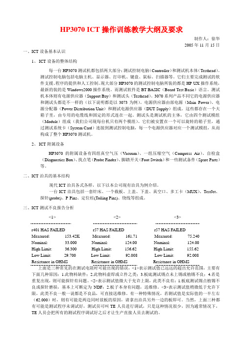
HP3070 ICT操作训练教学大纲及要求制作人:徐华2005年11月15日一、ICT设备基本认识1、ICT设备的整体结构每一台HP3070测试机都包括两大部分:测试控制电脑(Controller)和测试机本体(Testhead)。
测试控制电脑包括电脑主机、显示器、打印机、键盘、鼠标、扫描器等。
它们主要完成测试的软件支援、程序的提供和人工控制。
现大部分HP3070的测试控制电脑所装的都是HP-UX操作系统,最新的装的是Windows2000操作系统。
而测试软件是BT-BASIC(Board Test Basic)语言。
测试机本体则有电源供应器(Support Bay)和测试头(Testhead)。
3070系列产品不同它的电源供应器和测试头都是不一样的(以下说明都是以3073为例)。
电源供应器由部电源(Main Power)、电源分配器(Power Distribution Unit)和测试电源供应器(DUT Supply)组成。
这些都存在一个大箱子里,由专用的电缆线和固定的形式连在一起。
测试头是测试机的主体,它由四个测试模组(Module)组成(我们公司现每台机只有两个模组)。
它们被安置在一个可以旋转的箱子里,通过测试系统卡(System Card)连接到测试控制电脑,每一个电源供应器对应一个测试模组,从而构成了整个HP3070测试机。
2、ICT附属设备HP3070的附属设备有四组真空气压(Vacuum)、一组压缩空气(Compress Air)、自检盒(Diagnostics Box)、找点笔(Probe Finder)、脚踏开关(Foot Switch)和一些测试备件(Spare Parts)等。
二、ICT治具的基本结构现代ICT治具各式各样,以下以本公司现有治具为例介绍。
一台ICT治具包括一套针床、一个载板、上盖、下盖、真空口、多工卡(MUX)、TestJet、探针(probe)、P-Pins、定位柱(Tolling Pins)、绕线等组成。
3360台式电子万能试验机
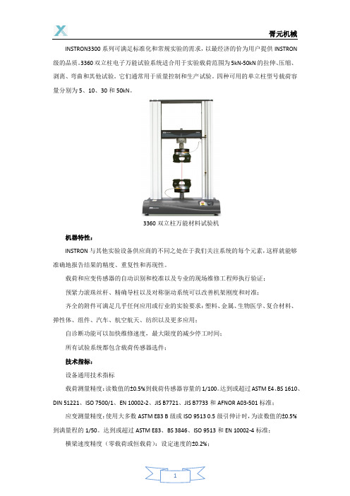
INSTRON3300系列可满足标准化和常规实验的需求,以最经济的价为用户提供INSTRON 级的品质。
3360双立柱电子万能试验系统适合用于实验载荷范围为5kN-50kN的拉伸、压缩、剥离、弯曲和其他试验。
它们通常用于质量控制和生产试验。
四种可用的单立柱型号载荷容量分别为5、10、30和50kN。
3360双立柱万能材料试验机机器特性:INSTRON与其他实验设备供应商的不同之处在于我们关注系统的每个元素,这样就能够准确地报告结果的精度、重复性和再现性。
载荷和应变传感器的自动识别和校准以及专业的现场维修工程师执行验证;预紧力滚珠丝杆、精确导柱以及对称驱动系统可以改善机架刚度和对准;齐全的附件可满足几乎任何应用或行业的实验要求:塑料、金属、生物医学、复合材料、弹性体、组件、汽车、航空航天、纺织以及更多应用;自诊断功能可以加快维修速度,最大限度的减少停工时间;所有试验系统都包含载荷传感器选件;技术指标:设备通用技术指标载荷测量精度:读数值的±0.5%到载荷传感器容量的1/100。
达到或超过ASTM E4、BS 1610、DIN 51221、ISO 7500/1、EN 10002-2、JIS B7721、JIS B7733和AFNOR A03-501标准;应变测量精度:使用大多数ASTM E83 B级或ISO 9513 0.5级引伸计时,为读数值的±0.5%到满量程的1/50。
达到或超过ASTM E83、BS 3846、ISO 9513和EN 10002-4标准;横梁速度精度(零载荷或恒载荷):设定速度的±0.2%;工作电压:220或240 VAC ±10%,47-63Hz。
电源应无最大峰谷值高于平均电压10%的尖峰、电涌或涌冲;工作温度:+10-+38°C存储温度:-40-66°C湿度范围:+10%-+90%,无冷凝机器运行环境:针对正常的实验室条件设计。
测试机说明书改
测试键 资料寻找 键
列表控制 键
绝缘设定 键 萤幕字体 20*2 电源指示 灯
8、PASS-------------7、FALL-------------9、INIT-------------10、 SGLE------------11、PIN FIND---------探 测点钎孔 12、A PORT/B PORT----治具接 插端(带 保险)
16、 耗电:8W
三、操 作流程 图
是
插上待测标准线材 连按READ键二次
按DUMP键 比对标准资料 正确
按TEST键
LCD显示OK
按ISOL键 调整漏电阻值
LCD显示 EMPTY(待测)
打开电源
LCD 显 示 SELF TEST PASSED
否 拔开转接治具线
是
按TEST键 否
LCD 显示
是
SELF TEST
5) ERROR FREE-------------------------
6) PIN FIND--------------------------
表示自我 测试正常
表示等待 下一条测 试
表示显示 的资料已 经结束
摇摆测试 试瞬间短 断路之锁 定
随时反应
搜寻测试 点(请参 考第5 章)
7) PLUG IN LEFT------------------------
7
…………
…………
………
双头标准
资料显示
说明……
………… …………
7
…………
…………
………
搜寻测试
点………
…………
…………
8
…………
…………
电位器旋钮寿命试验机PPT学习教案
第3页/共6页
1.测试工位:1组(机器不能判断好坏,只能做完一定次数,在人工 确认)
2.电机;90W 3.次数;0~999999次(可设定) 4.速度;3~60c.p.m可调 5.旋转行程;0-180度(可调,单边旋转) 6.体积;约600(L)*500(D)*900(H)mm 7.重量;50kg 8.电源;1∮,220V
电位器旋钮寿命试验机
会计学
1
电位器旋钮寿命试验机
FL-8634电位器进行寿命测试。
机器动作0-180度旋转,旋转角度可调节
(手动调节,带刻度盘)。本机具有速度
可调、次数设定,并达到次数后数据保持
停机。放置产品时要对电位器和机器旋转
角度原点(及0度位置)。
第2页/共6页
第4页/共6页
谢谢阅读! 欢迎登陆公司网站查询!
第5页/共6页
- 1、下载文档前请自行甄别文档内容的完整性,平台不提供额外的编辑、内容补充、找答案等附加服务。
- 2、"仅部分预览"的文档,不可在线预览部分如存在完整性等问题,可反馈申请退款(可完整预览的文档不适用该条件!)。
- 3、如文档侵犯您的权益,请联系客服反馈,我们会尽快为您处理(人工客服工作时间:9:00-18:30)。
向正柱2010/11
Working on Better Solutions
Version 1.0
Copyright © 2007 ,CHROMA Inc.
1
致力創新 追求卓越
CHROMA VLSI Test System
系統架構介紹
Working on Better Solutions
Level Set 1: VIL,VIH,VOL,VOH, IOL,IOH,VCl, VCH Level Set 2: VIL,VIH,VOL,VOH, IOL,IOH,VCl, VCH
VIH
VCL VCH
Level Set 3: VIL,VIH,VOL,VOH, IOL,IOH,VCl, VCH
VIL
DEVICE POWER SUPPLY ( DPS ) PRECISION VOLTAGE REFERENCE ( PREF )
PPMU
Version 1.0ቤተ መጻሕፍቲ ባይዱ
Copyright © 2007 ,CHROMA Inc.
3
高速功能方塊圖
INPUT FORMAT F DATA DTG PIN DRIVER SBC F0 F1 FCLK ACTIVE LOAD
V oltage Characteristic (DC Testing)
Time Characteristic (AC Testing)
Fig 1-1-1
Working on Better Solutions
Version 1.0
Copyright © 2007 ,CHROMA Inc.
16
管腳定義檔 (.DEC)
Vref<Vo of DUT
Iol
Iol
Iol
Vref
DUT
Vref
DUT
Vref
Ioh
Ioh
Ioh
Working on Better Solutions
Version 1.0
Copyright © 2007 ,CHROMA Inc.
6
參考電壓原理
level ref:
Per-pin level : Vil, Vih, Vol, Voh, Iol, Ioh, Vref. Pin level : Cll (clamp low level),Clh (clamp high level).
Version 1.0
Copyright © 2007 ,CHROMA Inc.
9
測試程序檔案架構1
Working on Better Solutions
Version 1.0
Copyright © 2007 ,CHROMA Inc.
10
測試程序檔案架構2
Working on Better Solutions
Z DATA
Working on Better Solutions
Version 1.0
Copyright © 2007 ,CHROMA Inc.
4
數字通道方塊圖
VIH CLH
PMU PPMU
INPUT WAVEFORM =F-DATA +DTG/SBCMK +INPUT FORMAT
CLL
PDCL RELAY
M-DATA Z-DATA F-DATA
CTG
COMPARE LOW VOL
Working on Better Solutions
Version 1.0
Copyright © 2007 ,CHROMA Inc.
5
動態負載原理圖
Vref=Vo of DUT Or DUT is open
Vref>Vo of DUT
Version 1.0
Copyright © 2007 ,CHROMA Inc.
11
圖形/主程序-編譯
Source program (XXXXXX.pat)
Compiling
Object program (XXXXXX.ppo)
Source program (XXXXXX.pln)
Compiling
Version 1.0
Copyright © 2007 ,CHROMA Inc.
15
數字信號構成要素
直流參數 DC 功能參數 Function 交流參數 AC
(V oltage)
Logical Characteristic (Functional Testing)
Higher Level Lower Level (Time) T1 T2
Version 1.0
Copyright © 2007 ,CHROMA Inc.
2
測試系統方塊圖
TEST HEAD
HIGH-SPEED CONTROLLER
Working on Better Solutions
COMPUTER / WORK STATION
TIMING GENERATOR LOCAL MEMORY
Version 1.0 Copyright © 2007 ,CHROMA Inc.
20
DEC的格式3 - UR_PIN_GROUP
用途:宣告繼電器控制管腳群組名 UR_PIN_GROUP {
ur_pin_group_name = ur_pin_name operand ur_pin_name operand …; . . ur_pin_group_name = ur_pin_name operand ur_pin_name operand…; } 範例:
NRZ
DNRZ RZ RO
IO FORMAT D DATA IOTG IO_NRZ IO_RO IO_RZ RESPONSOE RECORDER M DATA C DATA CTG OUTPUT FORMAT EDGE WINDOW MASK/ENABLE COMPARATO R
IO_ON IO_OFF
UR_PIN_GROUP { UR_RC_PINS= UR_PIN0+UR_PIN10; }
Working on Better Solutions
Version 1.0
Copyright © 2007 ,CHROMA Inc.
21
DEC的格式4 - POWER_PIN_GROUP
用途:宣告電源管腳群組名稱 POWER_PIN_GROUP {
7
LCD PE card高壓數字比較通道原理
LV
ALD
HV
Working on Better Solutions
Version 1.0
Copyright © 2007 ,CHROMA Inc.
8
致力創新 追求卓越
CHROMA VLSI Test System
測試程序架構
Working on Better Solutions
pin_type:管腳種類
IN OUT IO DPS PREF LCD UR GND 輸入腳. 輸出腳. 雙向腳. 電源腳,使用DPS供電. 電源腳,使用PREF供電. 高壓輸出腳. 繼電器控制腳,系統提供 接地腳.
Working on Better Solutions
Version 1.0
Copyright © 2007 ,CHROMA Inc.
18
PIN_LIST 範例
PIN_LIST ( name ) { pin_name = ate_pin [:ate_pin] = dut_pin = pin_type ; . . pin_name = ate_pin [:ate_pin] = dut_pin = pin_type ; }
PIN_LIST ( ft_package ) { SYNC LE OC D1 Q7 Q8 Vcc Gnd } =1 =9 =25 =26 =23 =20 = 0 = = 2 = IN ; = 11 = IN ; = 1 = IN ; = 3 = IN ; = 16 = OUT ; = 19 = OUT ; = 20 = DPS ; = 10 = GND ;
MUX
VOH
…………… ……………
Level Set 240: VIL,VIH,VOL,VOH, IOL,IOH,VCl, VCH
VOL
Pin Electronics
Working on Better Solutions
Version 1.0
Copyright © 2007 ,CHROMA Inc.
Copyright © 2007 ,CHROMA Inc.
13
致力創新 追求卓越
CHROMA VLSI Test System
測試程序
Working on Better Solutions
Version 1.0
Copyright © 2007 ,CHROMA Inc.
14
測試數字器件的要件
Working on Better Solutions
ALGORITHMI C PATTERN GENERATOR
FORMAT GENERATOR RESPONSE ANALYZER
LOW-SPEED CONTROLLER
DEVICE UNDER TEST
LEVEL REFERENCE
PARAMETRIC MEASUREMENT UNIT ( PMU )
Working on Better Solutions
Version 1.0
Copyright © 2007 ,CHROMA Inc.
17
DEC檔的格式1-PIN_LIST
PIN_LIST (defined name){
pin_name = ate_pin [:ate_pin] = dut_pin = pin_type … pin_name = ate_pin [:ate_pin] = dut_pin = pin_type }